

Dell Inspiron 7500 User Manual

Dell™Inspiron™7500SystemReference
Information in this document is subject to change without notice.
©1999–2000 Dell Computer Corporation. All rights reserved.
Reproduction in any manner whatsoever without the written permission of Dell Computer Corporation is strictly forbidden. Trademarks used in this text: Dell, the DELL logo,
MegaBay, and Inspiron are trademarks of Dell Computer Corporation; Microsoft, Windows, MS-DOS, and WindowsNT are registered trademarks of Microsoft Corporation;
Intel and Pentium are registered trademarks, and Celeron is a trademark of Intel Corporation; Adobe is a trademark of Adobe Systems Incorporated, which may be registered
in certain jurisdictions.
Other trademarks and trade names may be used in this document to refer to either the entities claiming the marks and names or their products. Dell Computer Corporation
disclaims any proprietary interest in trademarks and trade names other than its own.
Initial release: 20 Sep 1999
Last revised: 17 Aug 2000
Conventions
Technical Overview
Using the Computer
Utilities and Drivers for Windows 98
Utilities and Drivers for Windows NT
Technical Specifications
Setup Program
System Codes and Messages
Passwords and Security
Ports and Connectors
Power Sources
Power Conservation
Removing and Replacing Parts
Documentation

Back to Contents Page
13.3-InchLCDBracketsandCarrierTrayRemoval:Dell™Inspiron™7500
This procedure assumes that you have removed the front bezel and the 13.3-inch LCD panel. To remove the brackets from the LCD panel, follow
these steps:
1. Detach the LCD wire harness from connector CN1 on the top left side of the inverter board.
2. Remove the (4) 6-mm screws from the sides of the mounting brackets.
3. Remove the brackets from the LCD panel.
To remove the 13.3-inch LCD panel from the carrier tray, follow these steps:
1. Remove any Kapton tape covering the CCFL cable.
2. Gently pull the cable out of its connector.
3. Remove any Kapton tape from the LCD wire harness.
4. Disconnect the LCD wire harness from the LCD panel.
5. Lift the LCD panel out of carrier tray.
Back to Contents Page
NOTICE: The metal on the carrier tray is sharp. Be careful not to cut yourself.
Back to Contents Page
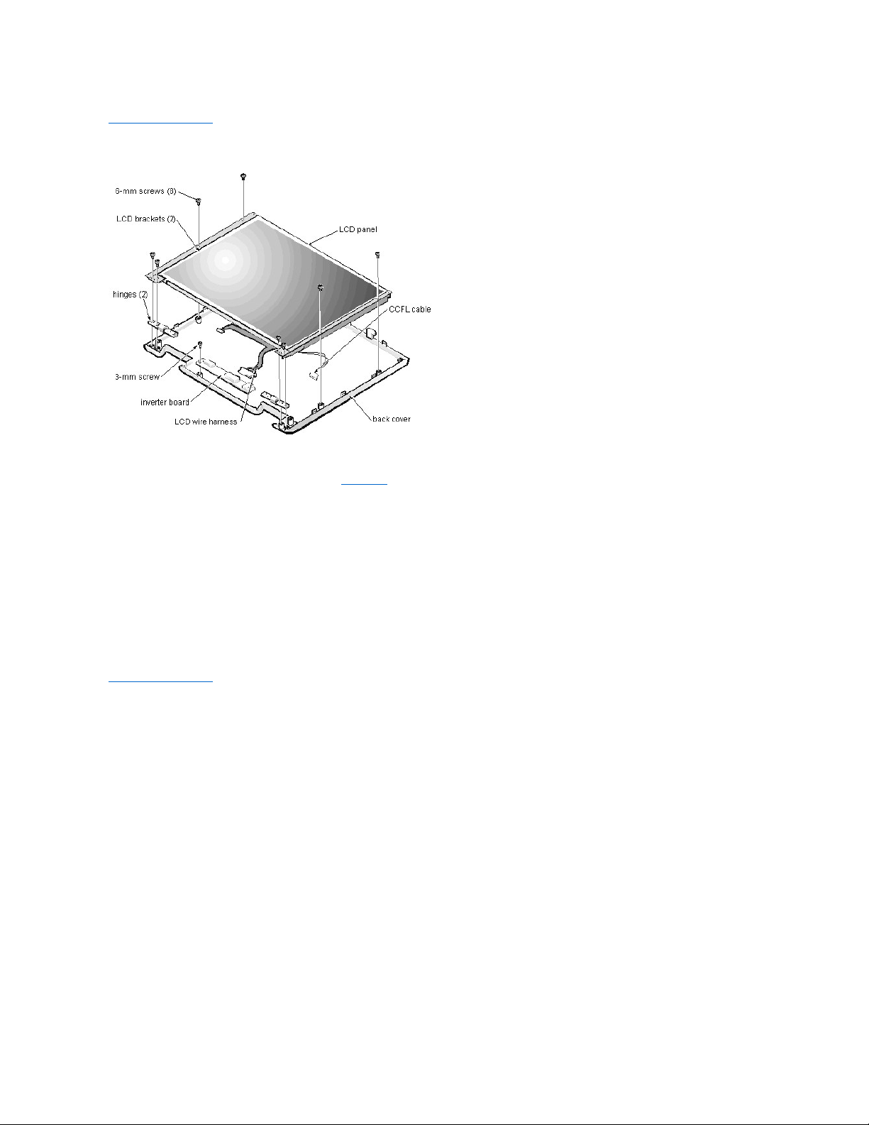
13.3-InchLCDPanelRemoval:Dell™Inspiron™7500
This procedure assumes that you have removed the front bezel. Follow these steps to remove the 13.3-inch LCD panel:
1. Remove the (8) 6-mm screws that secure the left and right LCD brackets to the front plastic cover.
2. Detach the LCD wire harness from connector CN2 on the right side of inverter board.
3. If present, carefully remove the grounding tape between the inverter board and LCD panel.
4. Loosen the 3-mm screw securing the inverter board.
5. Lift the LCD panel, LCD brackets, and carrier tray, as a unit, out of the back cover.
Rotate upward from the bottom of the panel because the top slides underneath the plastic hooks.
6. Remove the hinges, which were previously held in place by pressure and screws.
To remove the inverter board, follow these steps:
1. Remove the 3-mm screw securing the inverter board to the back cover.
2. If you have not removed the LCD panel, disconnect the LCD wire harness from connectors CN1 and CN2 on the inverter board.
3. Remove the inverter board from the back cover.
Back to Contents Page
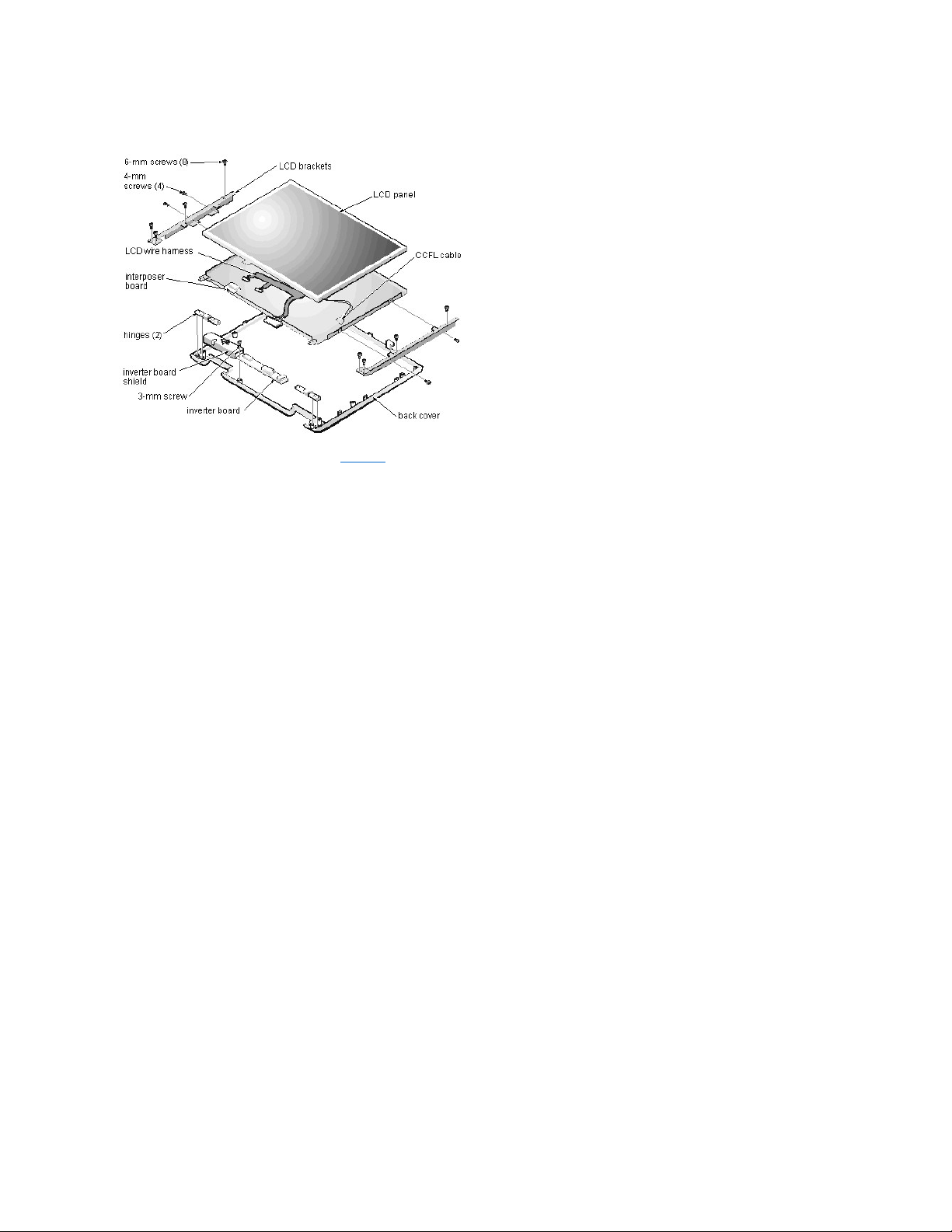
14.1-InchLCDPanel,Brackets,andCarrierTrayRemoval:Dell™Inspiron™7500
This procedure assumes that you have removed the front bezel. Follow these steps to remove the 14.1-inch LCD panel:
1. Remove the (8) 6-mm screws that secure the left and right LCD brackets to the front plastic cover.
2. Detach the CCFL cable from connector CN2 on the right side of inverter board.
3. Carefully remove the grounding tape between the inverter board and LCD panel.
4. Remove the 3-mm screw securing the inverter board, and unsnap the inverter board from the back cover.
5. Lift the LCD panel, LCD brackets, and inverter board as one unit out of the back cover.
Rotate upward from the bottom of the panel because the top slides underneath the plastic hooks.
6. Remove the hinges, which were previously held in place by pressure and screws.
To remove the LCD brackets from the LCD panel, follow these steps:
1. Remove the (4) 4-mm screws from the sides of the LCD brackets.
2. Remove the brackets from the LCD panel.
To remove the LCD panel from the carrier tray, follow these steps:
1. Lift the inverter board shield, pull it slightly away from the panel to expose the cabling, and detach the LCD wire harness from connector CN1 on the inverter
board.
2. Remove any Kapton tape covering the CCFL cable on the back of the LCD.
3. Gently pull the interposer board off the connector to the LCD panel.
4. Lift the LCD panel up and remove any tape between the LCD wire harness and the carrier tray.
5. Disconnect the LCD wire harness from the LCD panel.
6. Lift the LCD panel out of the carrier tray.
7. Disconnect the LCD wire harness from the LCD panel.
NOTICE: The metal on the carrier tray is sharp. Be careful not to cut yourself.
Back to Contents Page
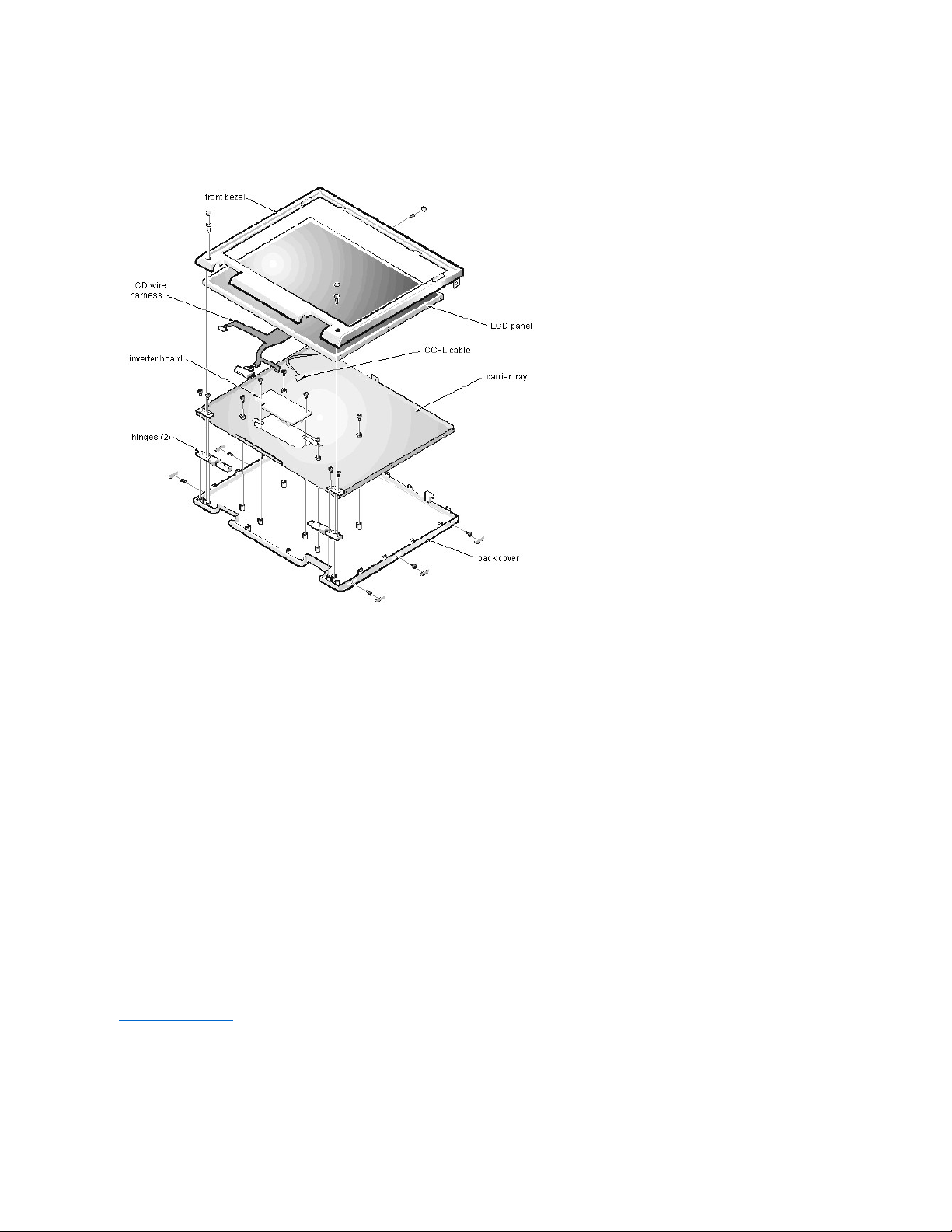
15-inchLCDPanelRemoval:Dell™Inspiron™7500
To remove the 15-inch LCD panel, perform the following steps:
1. Turn the computer over and remove the 4 screws from the bottom of the computer.
2. Turn the computer back over and open the display.
3. Remove the plastic hinge covers.
4. Insert a small flat-blade screwdriver or a similar plastic tool along the top-right edge of the keyboard, above the row of function keys. Working
from right to left, free the keyboard by prying it toward the front of the unit. When free, lift the top of the keyboard slightly to clear the palmrest
assembly.
5. Remove the keyboard bracket (located in the upper-right corner of the keyboard).
6. Remove the four screws that secure the two hinges.
7. Unplug the LCD wire harness and lift the assembly off the computer base.
To remove the front bezel, follow these steps:
1. Remove the two rubber screw covers and screws on the LCD near the hinge. Remove the remaining three plastic screw covers and screws,
one on either side and one in the front.
2. With all screws removed, unsnap the front bezel from the back cover and remove the bezel from the assembly.
To remove the LCD panel, hinges, and inverter board, follow these steps:
1. Remove the 4 remaining screw covers and screws on the sides of the LCD.
2. With all screws removed, lift the LCD panel out and disconnect the CCFL wire from the inverter board.
3. Detach the LCD wire harness from connector CN2 on the right side of the inverter board.
4. Carefully remove the grounding tape between the inverter board and the LCD panel.
5. Remove the two 2.5-mm screws securing the inverter board to the back cover.
6. Remove the inverter board from the back cover.
To reassemble, perform the steps in reverse order.
Back to Contents Page

Back to Contents Page
ACAdapter:Dell™Inspiron™7500
Back to Contents Page
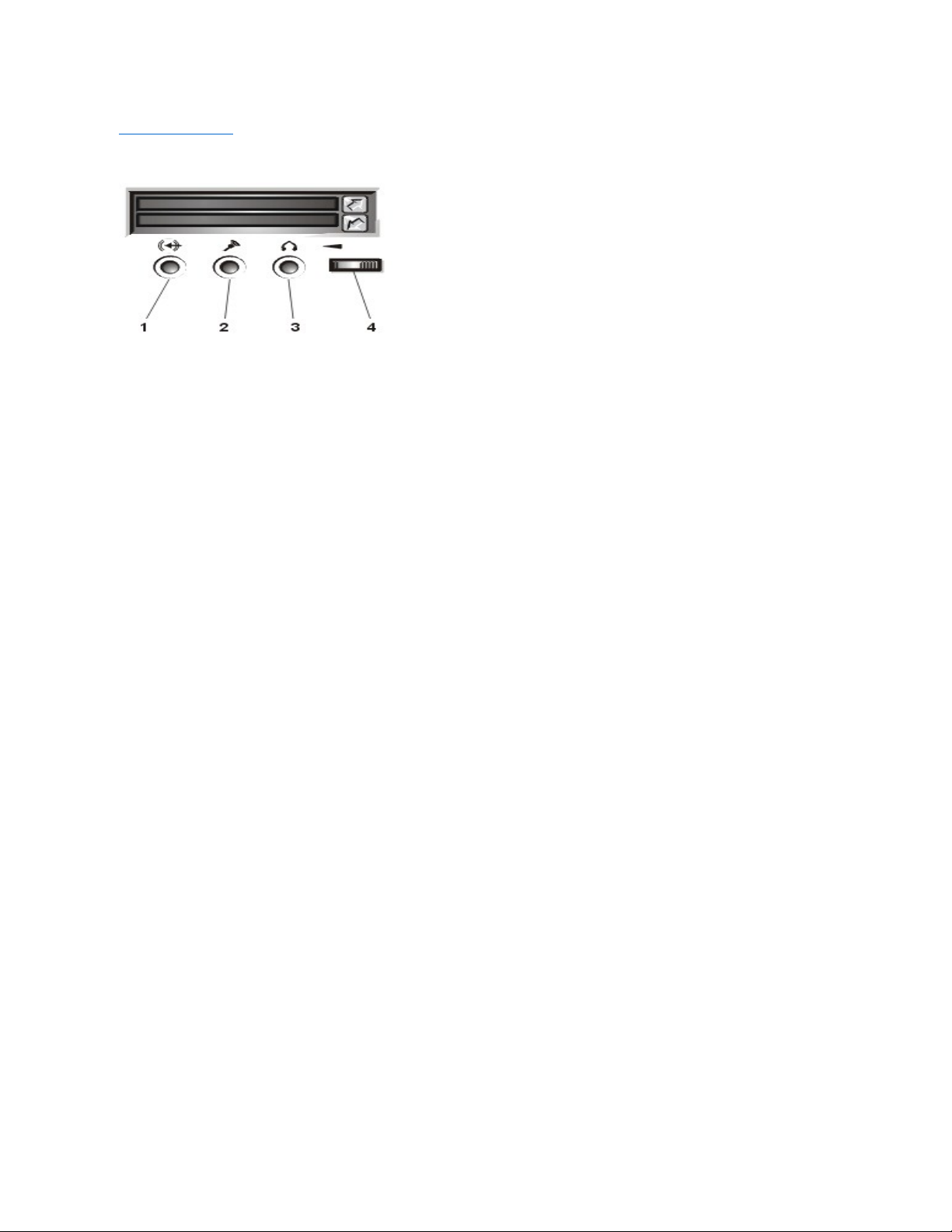
AudioJacks:Dell™Inspiron™7500
Back to Contents Page
AudioDevices:Dell™Inspiron™7500
You can connect speakers, a microphone, headphones, and record/playback devices such as cassette players, CD players, and VCRs to the
audio connectors on the computer. The connectors are located directly under the PC Card slot. Dell recommends using amplified speakers for the
best sound.
Connect headphones or speakers to the headphone connector on the right of the audio connectors. Connect a microphone to the microphone-in
connector in the middle. Connect record/playback devices such as cassette players, CD players, and VCRs to the line-in connector on the left.
See your Microsoft® Windows® 98 documentation for the location of sound application programs such as mixers and volume control.
You can control the sound coming from the external speakers and the computer's integrated speakers with the volume control dial. You can also
use the keyboard to adjust the volumes. Press to lower the volume. Press to increase the volume. Press to enable or
disable both the integrated and external speakers.
See Drivers for information about reinstalling the audio drivers. The drivers are located on the Dell Inspiron 7500 System Software CD.
Back to Contents Page
NOTE: If no sound comes from the speakers, make sure that the sound is not disabled. Press and check the volume
control dial.
Back to Contents Page
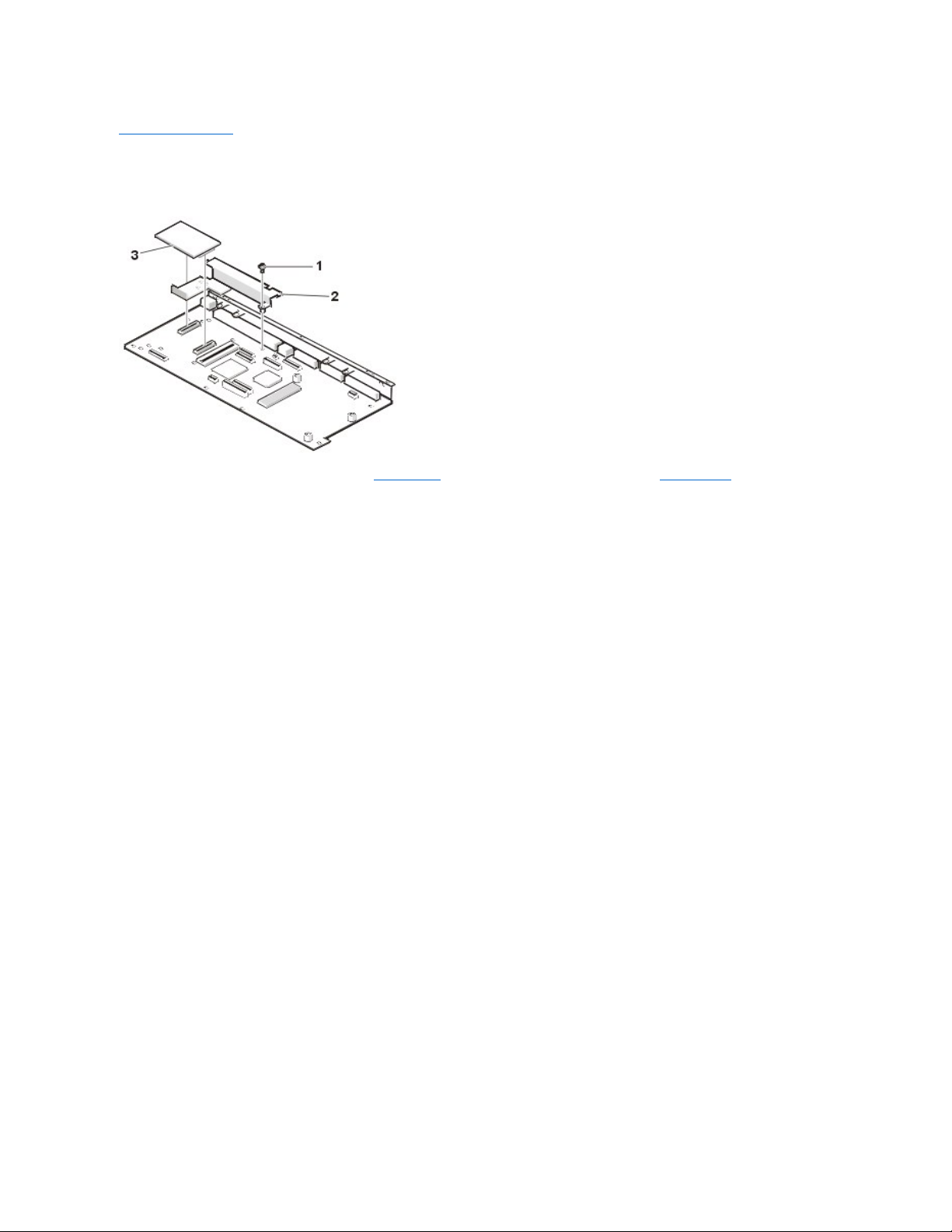
AudioCardandAudioThermalShieldRemoval:Dell™Inspiron™7500
****New artwork pending
This procedure assumes that you have removed the system board from the plastic case and have removed the PC Card cage from the system
board. To remove the audio card and audio thermal shield, follow these steps:
1. Gently pull the audio card off of connectors JP12 and JP13 on the system board. Do not rock the card to remove it, because this may
damage the connectors.
2. Remove the 10-mm screw securing the audio thermal shield, and then remove the shield.
Back to Contents Page
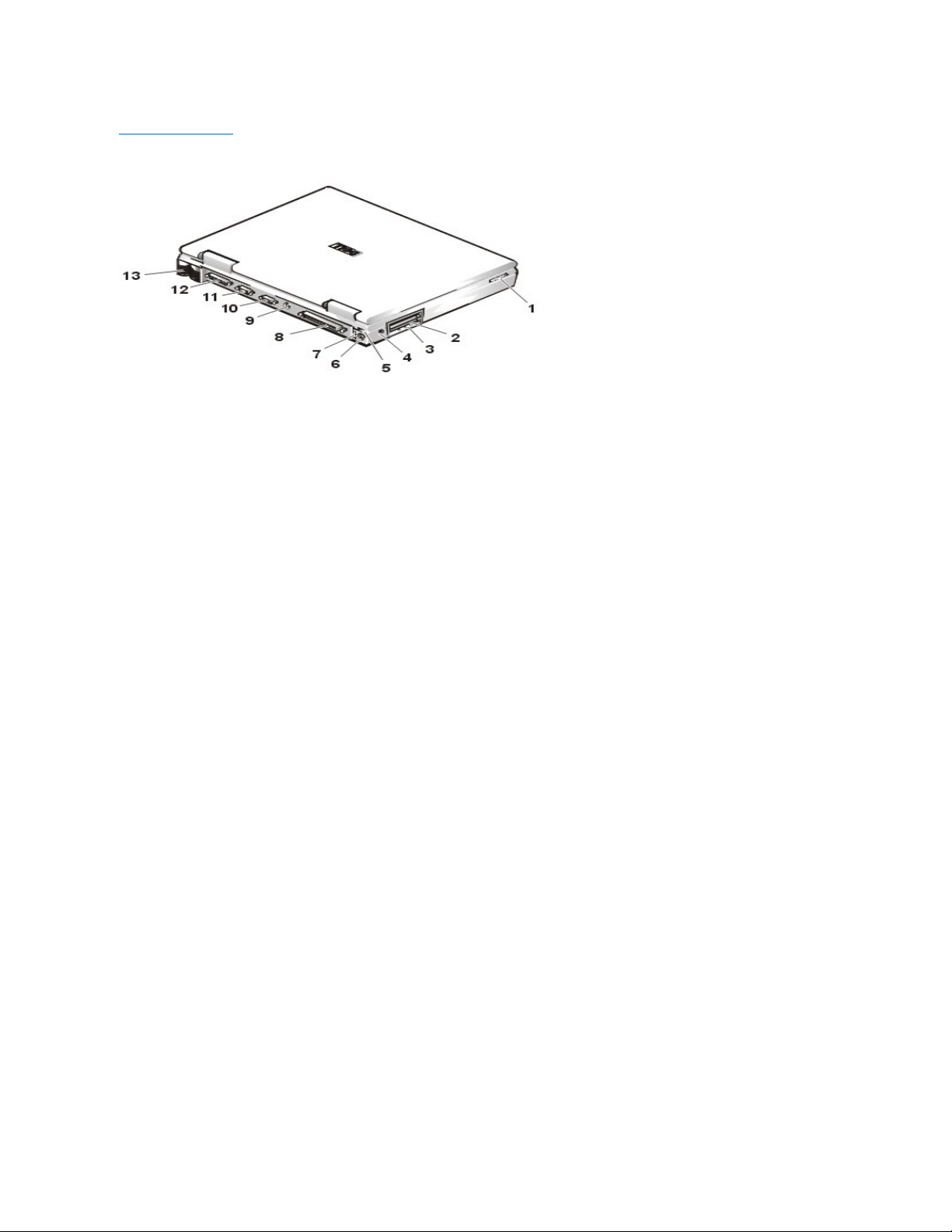
ComponentLocations(BackView):Dell™Inspiron™7500
Back to Contents Page
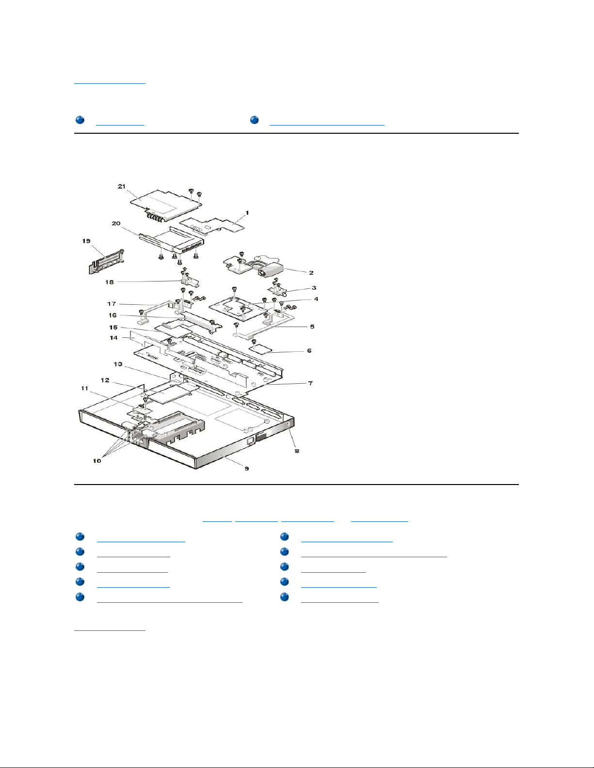
Base Assembly Component Removal:Dell™Inspiron™7500
Base Assembly
****New artwork pending
Base Assembly Component Removal
The following procedures assume that the keyboard, thermal shield, display assembly, and palmrest assembly have been removed.
Back to Contents Page
Base Assembly
Base Assembly Component Removal
PC Card Heat Sink Removal
Heat Exchanger/Fan Removal
DC-DC Board Removal
Processor Board and Memory Module Removal
Hinge Saddle Removal
RJ-11 Card Removal
System Board Removal
PC Card Cage Removal
Audio Card and Audio Thermal Shield Removal
Latch Assembly Removal
Back to Contents Page
BatteryChargeGauge:Dell™Inspiron™7500
Back to Contents Page
RemovingandInstallingaBattery:Dell™Inspiron™7500
Back to Contents Page
FrontBezelRemoval:Dell™Inspiron™7500
This procedure assumes that you have removed the display assembly from the computer base. To remove the front bezel, follow these steps:
1. Use a dental pick to pry the rubber screw covers off of the bottom 2 screws and the rubber bumpers off of the top 2 screws.
2. Remove the (4) 6-mm screws from the front bezel.
3. Unsnap the front bezel from the back cover and remove it from the assembly.
Carefully insert your fingers between the LCD panel and the bezel. Roll the plastic up slightly to insert your fingers further in, and then lift upward to free the snaps.
Start at the middle bottom and then work around.
When replacing the bezel, ensure that the LCD wire harness is routed correctly through the openings in the back cover and is not pinched.
Back to Contents Page
UsingtheComputer:Dell™Inspiron™7500
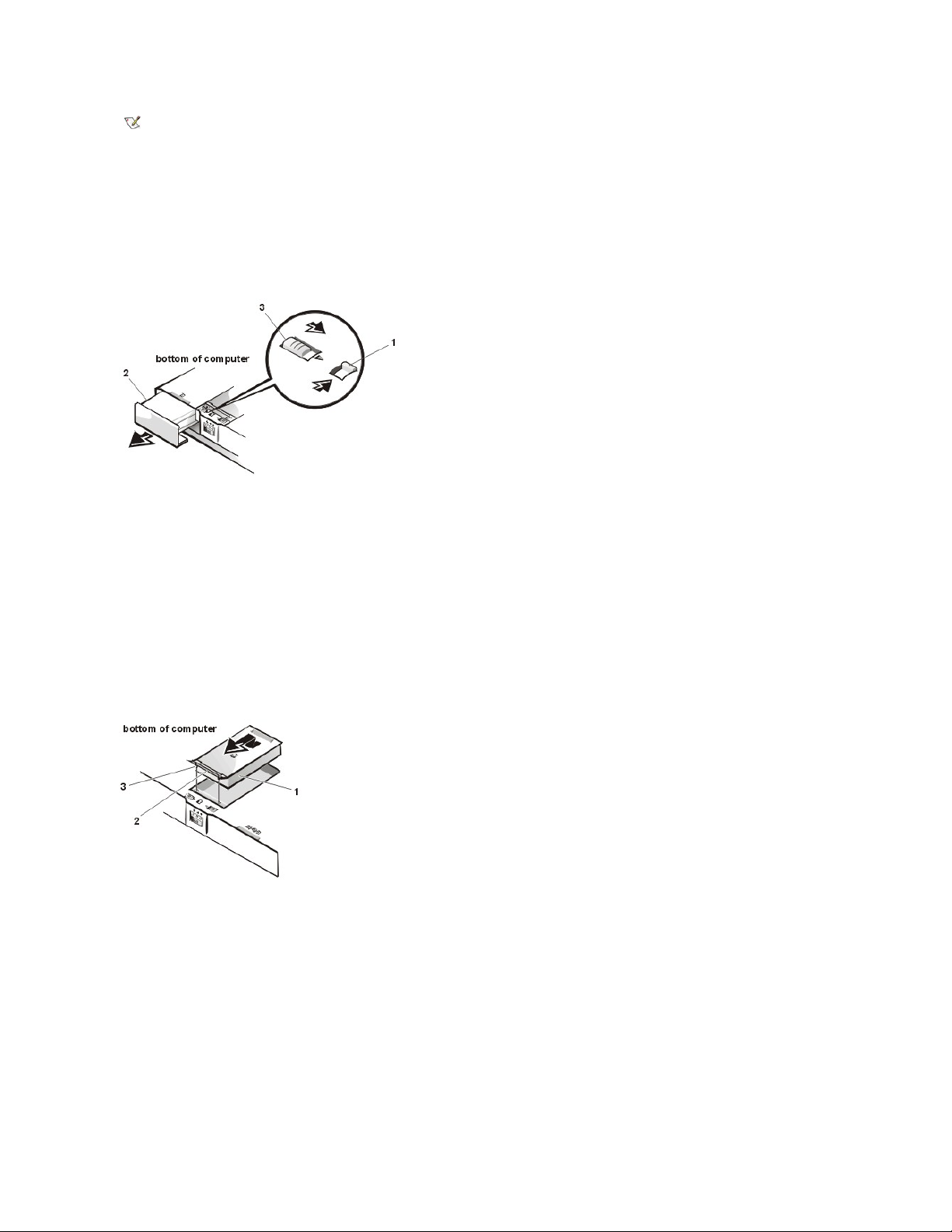
Storage Devices
Removing and Installing a Device in the Media Bay
The media bay holds a second battery, a combination CD-ROM drive/diskette drive, a combination DVD-ROM drive/diskette drive, a combination
DVD-ROM drive/LS-120 diskette drive, or an optional hard-disk drive.
To remove a device from the media bay, perform the following steps:
1. Save any open files.
2. Shut down the computer.
3. Remove the currently installed device from the media bay.
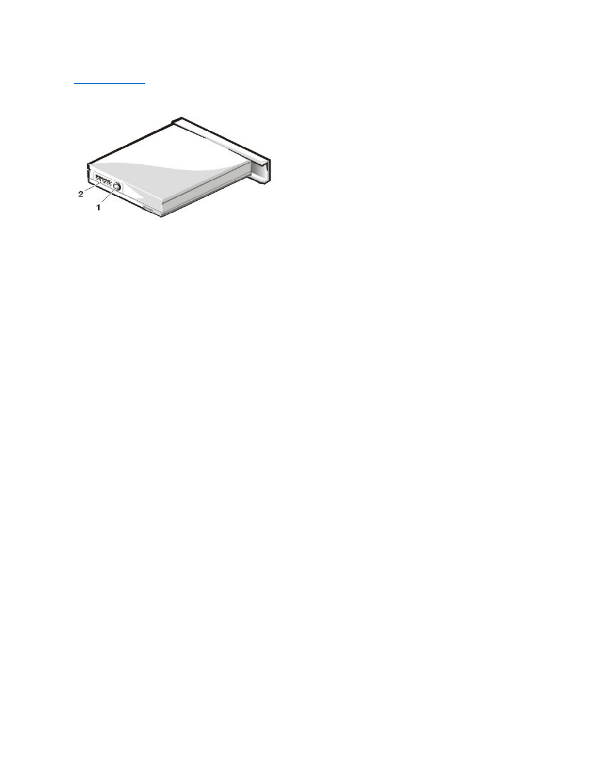
Close the display and turn the computer over. Push the latch lock to the unlocked position (see Figure 1), and slide the latch release in the
direction of the arrow. Keep holding the latch release with one hand while pulling the device out of the media bay with the other.
Figure 1. Removing Devices From the Media Bay
4. Install the new device in the media bay.
Insert the device into the media bay and push the latch lock back into the locked position. The label on the device will be facing away from
you when the computer is turned over.
5. Reboot the system.
Hard-Disk Drive
Storage Devices
Touch Pad
Audio Devices
PC Cards
Embedded Numeric Keypad
External Monitor
External Keyboard, Keypad, or Mouse
NOTE: All devices are removed and installed the same way.
1
Latch release
2
Combo module or secondary battery
3
Latch lock (unlocked position)
To install a hard-disk drive, perform the following steps.
1. Save any open files.
2. Shut down the computer and remove any installed batteries (see Figure 2).
Figure 2. Removing a Battery From the Media Bay
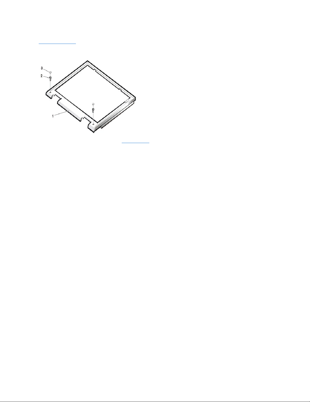
3. Remove the currently installed hard-disk drive (see Figure 3).
Turn the computer over, and loosen the two captive screws securing the hard-disk drive cover. The screws are held captive in the lip of the
carrier. A spring causes the front edge of the cover to pop up. If the front edge of the cover does not pop up, pull on one of the screws to lift
the front edge.
Figure 3. Removing the Hard-Disk Drive
4. Push the hard-disk drive forward until it stops, and then pull it up.
5. Remove the new drive from its packaging.
Save the original packaging to use when storing or shipping the hard-disk drive.
6. Slide the new drive into place.
NOTE: The computer's BIOS may not support hard-disk drives obtained from vendors other than Dell. Dell does not guarantee
compatibility or provide support for hard-disk drives obtained from other sources.
NOTICE: To prevent data loss, shut down your computer before removing or installing your hard-disk drive. Do not remove the
hard-disk drive if the computer is in suspend mode or save-to-disk mode or if the hard-disk drive access indicator is lit.
1
Latch lock (unlocked position)
2
Battery
3
Latch release
NOTICE: When the hard-disk drive is not in the computer, protect the drive from exposure to static electricity by storing it in
protective packaging.
1
Hard-disk drive
2
Hinge3Captive screws (2)
NOTICE: While sliding the drive in, do not force it into place.
There may be some resistance as the drive connects to its interface connector at the back of the bay.
7. Tighten the screws you loosened in step 3.
8. Test the drive by running the Hard-Disk Drives (Non-SCSI) test group in the Dell Diagnostics.
For information on running the diagnostics, see "Running the Dell Diagnostics" in Chapter 3 of the Dell Inspiron 7500 Reference and
Troubleshooting Guide.
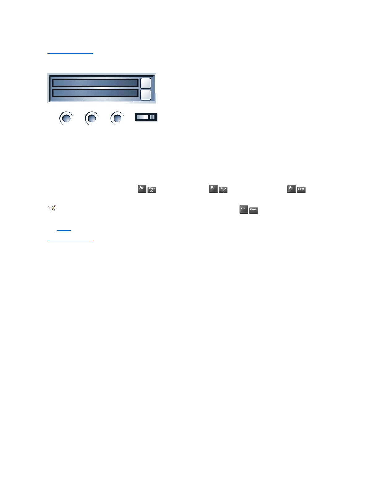
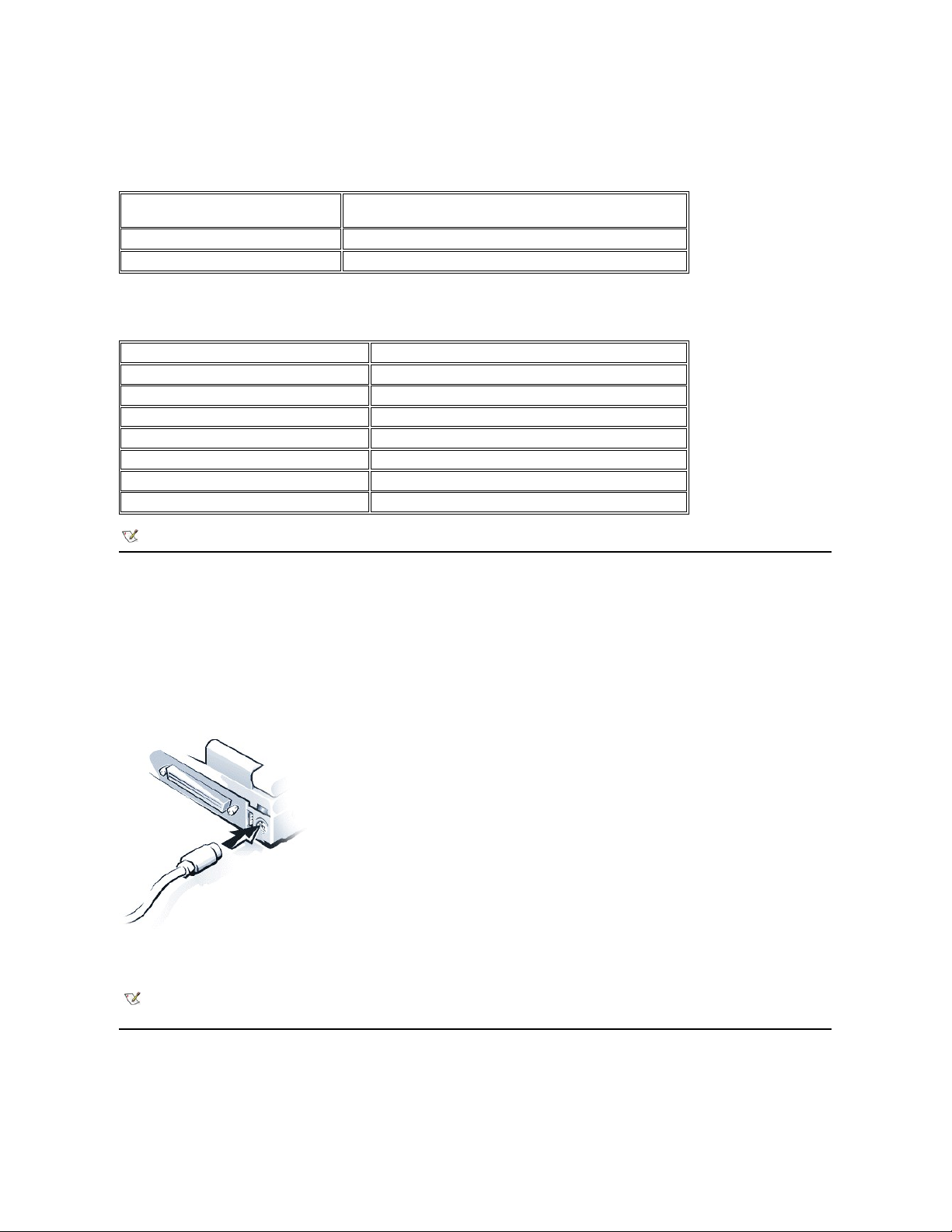
Audio Devices
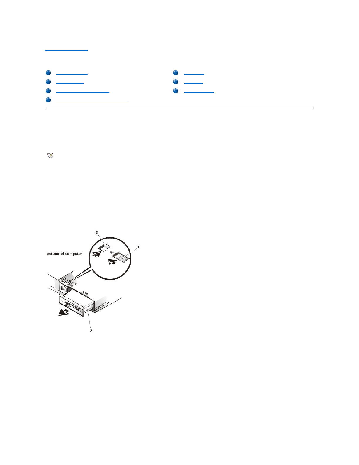
You can connect speakers, a microphone, headphones, and record/playback devices such as cassette players, CD players, and VCRs to the
audio connectors on the computer (see Figure 4). The connectors are located directly under the PC Card slot. Dell recommends using amplified
speakers for the best sound.
Figure 4. Audio connectors
Connect headphones or speakers to the line-out jack on the left of the audio connectors. Connect a microphone to the microphone jack in the
middle. Connect record/playback devices such as cassette players, CD players, and VCRs to the line-in jack on the right.
See your Microsoft®Windows®98 documentation for the location of sound application programs such as mixers and volume control.
You can control the sound coming from the external speakers and the computer's integrated speakers with the volume control dial. You can also
use the keyboard to adjust the volumes. Press to lower the volume. Press to increase the volume. Press to enable or
disable both the integrated and external speakers.
See Utilities and Drivers for Microsoft Windows 98 and Utilities and Drivers for Microsoft Windows NT® for information about reinstalling the audio
drivers. The drivers are located on the Dell Inspiron 7500 System Software CD.
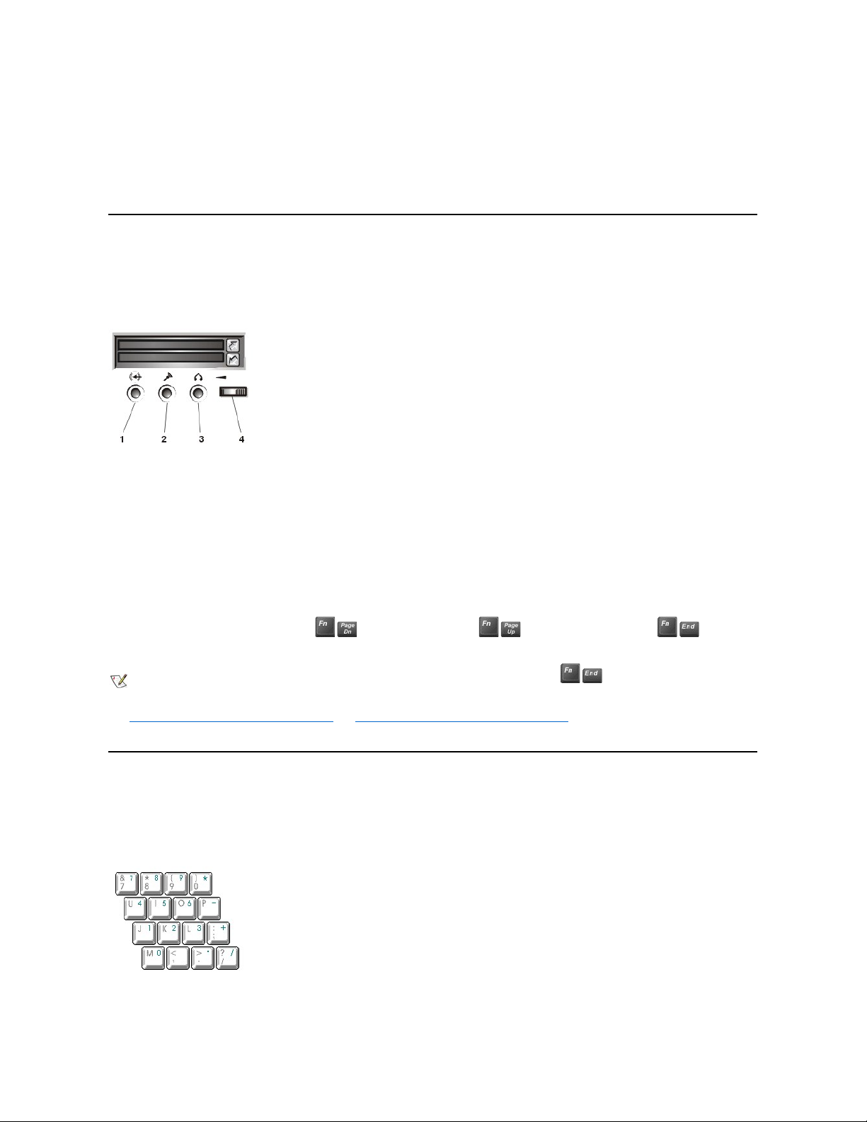
Embedded Numeric Keypad
As you work, you may want to use the embedded numeric keypad (see Figure 5) to enter numbers into a spreadsheet or financial program. The
embedded numeric keypad shares some of the keys on the computer's keyboard. The embedded keypad numbers and symbols are marked on
the right of the keypad keys in blue.
Figure 5. Embedded Numeric Keypad
To activate the embedded numeric keypad, press <Num Lock>. The Number Lock indicator lights up.
1
Line-in jack
2
Microphone jack
3
Line-out jack
4
Volume control dial
NOTE: If no sound comes from the speakers, make sure that the sound is not disabled. Press and check the
volume control dial.
To deactivate the embedded keypad, press <Num Lock>. The Num Lock indicator is no longer illuminated.
When the embedded keypad is activated, the key combinations in Table 1 temporarily disable specific keypad keys.
Table 1. Activated Keypad Functions
To use the embedded arrow keys, ensure that <Num Lock> is off. Press and hold <Fn> and the corresponding key displayed in Table 2.
Table 2. Deactivated Keypad Functions
External Keyboard, Keypad, or Mouse
You can connect a keyboard with a standard connector to the Personal System/2 (PS/2) connector on the computer by using an adapter available
from Dell. You can use the integrated keyboard even when an external keyboard is attached to the computer. You can also connect a Universal
Serial Bus (USB) keyboard to the computer's USB connector.
Attach a PS/2 mouse to the PS/2-compatible connector on the computer (see Figure 6) or a USB-compatible mouse to the USB connector. If you
attach a USB mouse to the computer, you do not need to reboot the computer in order to use the mouse. The touch pad device drivers that Dell
installed on your hard-disk drive work with a PS/2 mouse, serial mouse, or USB mouse from Dell.
Figure 6. Attaching a PS/2 Mouse
If you did not receive your mouse from Dell, you may need to install device drivers separately to use the mouse. This software is usually included
with mouse installation kits.
Touch Pad
The PS/2-compatible touch pad detects the position of your finger over a touch-sensitive area and provides the computer full mouse functionality.
The touch pad's two buttons correspond to the left and right buttons on a standard mouse.
When Keypad Is Activated
(Number Lock Indicator ON)
Function
<Fn><key>
Enables the lowercase letter or primary function of that specific key
<Fn><Shift><key>
Enables the uppercase letter or shift function of that specific key
When Keypad Is Deactivated
Function
<Fn><j>
Performs the same function as pressing <End>
<Fn><7>
Performs the same function as pressing <Home>
<Fn><k>
Performs the same function as pressing the down-arrow key
<Fn><8>
Performs the same function as pressing the up-arrow key
<Fn><u>
Performs the same function as pressing the left-arrow key
<Fn><o>
Performs the same function as pressing the right-arrow key
<Fn><.>
Performs the same function as pressing <Delete>
NOTE: The embedded numeric keypad is automatically disabled if an external keyboard or keypad is connected to the computer.
NOTE: If you are using a PS/2 mouse that is not Microsoft-compatible and the mouse does not work properly, reboot the computer. If
the mouse still does not work, install the drivers from the diskette that came with the mouse and reboot the computer.

To move the cursor, lightly slide your finger over the smooth sensor area. To select an object, gently tap once on the surface of the touch pad. To
select and move (or drag) an object, position the cursor on the object and tap down-up-down on the touch pad. On the second down motion, leave
your finger on the touch pad and move the selected object by sliding your finger across the surface. To double-click an object, position the cursor
on the object and then tap twice.
To customize touch pad and cursor features, perform the following steps:
1. Click the Start button, point to Settings, and then click Control Panel.
The Control Panel window appears.
2. Double-click the Mouse icon.
3. Select the Touch Pad tab.
4. Make your selections. Click the Help button if you need more information.
Dell has already installed the touch pad drivers for you.
Installing the Touch Pad/Mouse Driver
See Utilities and Drivers for Microsoft Windows 98 and Utilities and Drivers for Microsoft Windows NT for information about reinstalling touch
pad/mouse drivers.
PC Cards
The computer has two slots (see Figure 7) into which up to two 3.3- or 5-volt (V) PC Cards that comply with the Personal Computer Memory Card
International Association (PCMCIA) standard and Japanese Electronic Industry Development Association (JEIDA) Release 4.2 can be installed.
Both PC Card slots support CardBUS technology. In addition, a zoomed video (ZV) port is available from the lower slot (slot 0). If you ordered an
Moving Pictures Experts Group (MPEG)-2 decoder PC Card from Dell, install it in the lower PC slot for high-performance graphics.
Figure 7. PC Card Slots
The computer supports two Type I, two Type II, or one Type III PC Card, including such memory devices as static random-access memory (SRAM)
cards that emulate diskettes, RAM cards, one-time programmable (OTP) ROM cards, and Advanced Technology Attachment (ATA) cards that
emulate integrated drive electronics (IDE) hard-disk drives. Also supported are input/output (I/O) cards such as modem communication cards,
local area network (LAN) cards, wireless LAN cards, small computer system interface (SCSI) cards, and sound cards. You can also use extended
PC Cards in the computer.
Installing a PC Card
The PC Card slot has two PC Card connectors and can hold up to two cards in one of the following configurations:
l A single Type I or Type II card (using either the top or bottom PC Card connector)
NOTE: Keep your fingers away from the touch pad while the computer is booting or loading the operating system. If you touch the touch
pad at either time, the cursor will not move until you remove your finger from the touch pad surface.
1
Top eject button
2
PC card
NOTE: A PC Card is not a boot device.
NOTICE: Take extra precautions if you use extended PC Cards in the computer. Extended cards are longer versions of standard
PC Cards. They fit into, and operate correctly with, the computer. However, they extend beyond the edge of the computer when
installed. If something strikes the exposed end of an installed card, the card or the system board can be damaged.
NOTICE: Because of space considerations, you may have trouble using two PC Cards in the computer if one of them is an
extended card. Always install an extended card in the top PC Card connector. Always remove an extended PC Card before you
pack the computer for traveling.

l One Type I card and one Type II card (using either connector)
l Two Type I cards or two Type II cards
l A single Type III card (using the bottom connector)
The type of card refers to its thickness, not its functionality. Because a Type III card is thicker than Type I and Type II cards, it takes up the entire
PC Card slot, although it uses only one PC Card connector.
PC Cards are generally marked (with a triangle or an arrow) to indicate which end should be inserted into the slot. The cards are keyed to prevent
incorrect insertion. If card orientation is not clear, see the documentation that came with the card.
You can install a PC Card while the computer is running. The PC Card is automatically detected. To install a PC Card, hold the card with its
orientation symbol pointing into the slot and the top side of the card facing up. Insert the card into the slot, and press in firmly until the card is
completely seated in the internal PC Card connector. If there is too much resistance when inserting the card, do not force the card. Check the
card's orientation, and try again.
When a PC Card is being used, the PC Card access indicator appears in the status display panel. The computer recognizes most I/O cards and
automatically loads the appropriate device driver. If you have older modem communications software that cannot use interrupt request (IRQ)8 or
higher, you must disable the serial port or infrared port to use the software.
Removing a PC Card
To remove a PC card from the top connector, press the top eject button twice (identified by an arrow pointing up). To remove a PC card from the
bottom connector, press the bottom eject button twice (identified by an arrow pointing down). If you are removing a Type III card, press the bottom
eject button twice.
The first time you press an eject button, the eject button itself pops out. The second time you press the eject button, the PC Card is released and
extends slightly from the slot. Grasp the end of the card, and pull it completely from the slot.
See Utilities and Drivers for Microsoft Windows 98 and Utilities and Drivers for Microsoft Windows NT for information on installing utilities and
drivers.
Configuring a PC Card
If you are using the Microsoft Windows 98 operating system, click the Start button, point to Settings, and then click Control Panel. Double-click
the PC Card to open the PC Card Properties window. For more information, check the documentation that came with your operating system.
You can also double-click the PC Card icon on the Windows 98 desktop.
External Monitor
Use the 15-pin video connector to attach an external monitor to the computer. If you reconfigure your hardware, you may need pin number and
signal information for the monitor connector. To connect an external monitor, perform the following steps.
1. Turn off the external monitor.
Set the monitor on a monitor stand, desktop, or other level surface near the computer.
2. Connect the external monitor's video cable to the computer.
Plug the monitor cable connector into the matching video connector at the back of the computer. If the cable is not permanently attached to
the monitor, connect it to the monitor also. Tighten all the screws on the video cable connector(s) to eliminate radio frequency interference
(RFI).
3. Connect your external monitor to a grounded AC power source.
Plug the three-prong connector on one end of the monitor's power cable into a grounded power strip or some other grounded power source.
If the cable is not permanently attached to the monitor, connect it to the monitor also.
The video image can be displayed on an external monitor, on the computer's display, or on both simultaneously. To toggle between the three
display modes, press <Fn><F8>.
If the external monitor is turned off when you boot the computer, and if the Video Display Device category is set to CRT Mode in the Main menu
of the Setup program, the computer sends the video image to the external monitor. In this case, you do not see an image on either the computer's
display or on the external monitor. To resolve this situation, turn on the external monitor or press <Fn><F8> to switch the video image to the
computer's display.
Whether you are using an appropriately equipped multifrequency monitor only or an external monitor and the built-in display simultaneously, you
can display up to 256 colors at a noninterlaced resolution of 1400 x 1050 pixels at a 32-bit color depth.
NOTICE: Do not place the external monitor directly on top of your portable computer, even if it is closed. Doing so can
crack the computer case, the display, or both.

Back to Contents Page
NOTE: When the external monitor and built-in display are used simultaneously, the refresh rate is always 60 hertz (Hz).

Back to Contents Page
Conventions:Dell™Inspiron™7500
The following subsections describe notational conventions used in this document.
Notes, Notices, and Cautions
Throughout this guide, blocks of text may be accompanied by an icon and printed in bold type or in italic type. These blocks are notes, notices, and
cautions, and they are used as follows:
NOTICE: A NOTICE indicates either potential damage to hardware or loss of data and tells you how to avoid the problem.
Typographical Conventions
The following list defines (where appropriate) and illustrates typographical conventions used as visual cues for specific elements of text throughout
this document:
l Interface components are window titles, button and icon names, menu names and selections, and other options that appear on the monitor
screen or display. They are presented in bold.
Example: Click OK.
l Keycaps are labels that appear on the keys on a keyboard. They are enclosed in angle brackets.
Example: <Enter>
l Key combinations are series of keys to be pressed simultaneously (unless otherwise indicated) to perform a single function.
Example: <Ctrl><Alt><Enter>
l Commands presented in lowercase bold are for reference purposes only and are not intended to be typed when referenced.
Example: “Use the format command to . . . .”
In contrast, commands presented in the Courier New font are part of an instruction and intended to be typed.
Example: “Type format a: to format the diskette in drive A.”
l Filenames and directory names are presented in lowercase bold.
Examples: autoexec.bat and c:\windows
l Screen text is a message or text that you are instructed to type as part of a command (referred to as a command line). Screen text is
presented in the Courier New font.
Example: The following message appears on your screen:
No boot device available
Example: “Type md c:\programs and press <Enter>.”
l Variables are placeholders for which you substitute a value. They are presented in italics.
Example: DIMM_x (where x represents the DIMM socket designation)
Back to Contents Page
Notes, Notices, and Cautions
Typographical Conventions
NOTE: A NOTE indicates important information that helps you make better use of your computer system.
CAUTION: A CAUTION indicates a potentially hazardous situation which, if not avoided, may result in minor or moderate injury.

Back to Contents Page
DC-DCBoardRemoval:Dell™Inspiron™7500
To remove the DC-DC board, gently pull the DC-DC board off of connectors JP11 and JP16 on the system board. Do not rock the board to
remove it, because this may damage the connectors.
Back to Contents Page
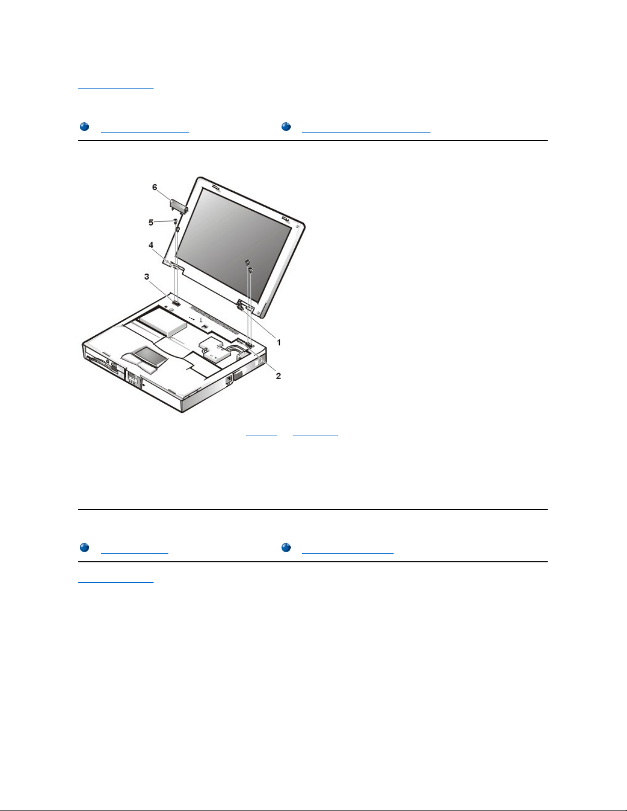
DisplayAssemblyandDisplayAssemblyComponentRemoval:Dell™Inspiron™7500
Display Assembly Removal
This procedure assumes that you have removed the keyboard and thermal shield. The following procedure applies to all LCD displays (15-inch
XGA, 15-inch SXGA+, and 15.4-inch SXGA).
1. Remove the left hinge cover.
Remove the two Phillips screws on the LCD wire harness on JP3. Use a dental pick or flat-blade screwdriver to pry each end of the connector to release it.
2. Close the display.
3. Remove the (4) 6-mm screws that secure the 2 hinges.
4. Unlatch the display assembly and lift the assembly off the computer base.
Display Assembly Component Removal
Back to Contents Page
Display Assembly Removal
Display Assembly Component Removal
Front Bezel Removal
15-Inch LCD Panel Removal

Back to Contents Page
Documentation:Dell™Inspiron™7500
Printed Documentation
To save PDF files (files with an extension of .pdf) to your hard-disk drive, right-click the document title, click Save Target As in Microsoft®Internet
Explorer or Save Link As in Netscape Navigator, and specify a location on your hard-disk drive.
Right-click only the following links:
Getting Started (.pdf) (835 KB)
Dell Inspiron 7500 System Reference and Troubleshooting Guide (.pdf) (1993 KB)
Dell Inspiron 7500 System Port Replicator User's Guide (.pdf) ( 3051 KB)
Dell Inspiron Systems Setup Guide (.pdf) (670 KB)
Dell Inspiron 7500 System Removing and Replacing Parts (.pdf) (1341 KB)
Online Documentation
Downloading the Help and Associated Files
1. Right-click the following link to the popup.ocx file:
popup.ocx
2. Click Save Target As in Microsoft Internet Explorer or Save Link As in Netscape Navigator, and specify c:\windows\system for Windows
98 or c:\winnt\ for Windows NT on your hard-disk drive.
3. Click the Start button on the Microsoft Windows®desktop, and then click Run.
4. Type regsvr32 popup.ocx and then press <Enter>.
5. Click OK when the installation is complete.
6. Right-click the following link to the Help file:
Dell Inspiron 7500 System Help (.chm) (846 KB)
7. Click Save Target As in Microsoft Internet Explorer or Save Link As in Netscape Navigator, and specify a location on your hard-disk drive.
Viewing the Help File
To view the Help file, perform the following steps:
1. Click the Start button on the Windows desktop, point to Programs, and then click Windows Explorer.
2. Navigate to the directory in which you saved the Help file.
3. Double-click the file (7500help.chm).
Printed Documentation
Online Documentation
You must right-click the link for a portable document format (PDF) file and save the file to your hard-disk drive. Attempting to
link directly to large PDF files causes your system to freeze.
NOTES:PDFfilesrequireAdobe™AcrobatReader,whichcanbedownloadedfromthefromtheAdobeWorldWideWebsiteat:
http://www.adobe.com/acrobat/.
To view a PDF file, launch Acrobat Reader. Click File–> Open and select the PDF file.
Compiled HTML Help files (files with an extension of .chm) require Microsoft Internet Explorer 4.0 or later.

Back to Contents Page

Back to Contents Page
Drivers:Dell™Inspiron™7500
Reinstalling Utilities and Drivers for Windows 98
Reinstalling Utilities and Drivers for Windows NT

Back to Contents Page
Utilities and Drivers for Microsoft®Windows®98:Dell™Inspiron™7500
Overview
This section explains how to install/reinstall Dell device drivers and utilities on your Dell computer running the Microsoft Windows 98 Second
Edition operating system. You may need to use this information under the following conditions:
l You are reinstalling the version of the Windows operating system that came with your computer, and you need to reinstall the drivers and
utilities that Dell provides.
l You have a new hard-disk drive and need to install all of the system software.
To install the system software, you need the following items:
l Dell Inspiron 7500 Software DVD Decoder CD (refer to "Installing the Software DVD Decoder")
l System Software CD
l CD-ROM or DVD-ROM drive installed in the media bay of the computer
l Microsoft Windows 98 Second Edition CD
l Microsoft Boot Disk Windows 98 Series diskette
The following subsections describe the installation instructions for the drivers and utilities that are provided on the System Software CD for use
with a system running the Windows 98 operating system.
Installing the Windows 98 Operating System
You must install Windows 98 on the hard-disk drive before you install any device drivers. To install Windows 98, perform the following steps:
1. Insert the Microsoft Boot Disk Windows 98 Series diskette into the diskette drive.
2. Restart the computer.
3. When the Microsoft Windows 98 Startup menu appears, insert the Microsoft Windows 98 CD into the CD-ROM or DVD-ROM drive.
4. Select Start Windows 98 Setup from CD-ROM and press <Enter>.
The Setup program runs ScanDisk to check your hard-disk drive.
5. When the hard-disk drive check is completed, type x to exit ScanDisk.
6. Follow the prompts on your screen to continue with the installation.
7. When prompted to create a start-up diskette, remove the Microsoft Boot Disk Windows 98 Series diskette, and click Next.
8. Label a blank, high-density diskette as instructed, insert the diskette into the diskette drive, and then click OK.
Follow the prompts on your screen to complete the installation.
Installing the Audio Driver
Overview
Installing the Internal Modem Driver (Optional)
Installing the Windows 98 Operating System
Installing the Software DVD Decoder (Optional)
Installing the Audio Driver
Creating the Save-to-Disk Suspend File
Installing the Video Driver
Installing the System Help
Installing the Touch Pad Driver
NOTE: Verify that Windows 98 is already installed on the hard-disk drive before you install any device drivers. For instructions, see the
preceding section, “Installing the Windows 98 Operating System.”

The audio driver allows you to customize the sound features of your computer. To install the audio driver, perform the following steps:
1. Save and close any open files, and exit any open application programs.
2. Insert the System Software CD into the CD-ROM or DVD-ROM drive.
3. If the Welcome to Windows 98 screen appears, click the x in the upper-right corner of the screen to close it and continue with the
installation.
4. Click the Start button, and then click Run.
5. In the Run dialog box, type x:\win98\audio\setup.exe, where x is the CD-ROM or DVD-ROM drive letter. The CD-ROM or DVD-
ROM drive letter is usually D.
6. Click OK.
7. At the Welcome screen, click Next.
8. At the Main Menu, the Upgrade Drivers radio button is selected. Click Next.
The audio files are copied to your hard-disk drive.
9. When prompted, be sure that the Yes, I want to restart my computer now radio button is selected, and then click Finish.
The New Hardware Found window appears, the driver is installed, and the installation is completed.
Installing the Video Driver
The video driver controls features such as video resolution and color palette. To install the video driver, perform the following steps.
1. Save and close any open files, and exit any open application programs.
2. Insert the System Software CD into the CD-ROM or DVD-ROM drive.
3. If the Welcome to Windows 98 screen appears, click the x in the upper-right corner of the screen to close it and continue with the
installation.
4. Click the Start button, and then click Run.
5. In the Run dialog box, type x:\win98\video\setup.exe, where x is the CD-ROM or DVD-ROM drive. The CD-ROM or DVD-ROM
drive letter is usually D.
6. Click OK.
7. When prompted to restart, click Finish. The computer restarts automatically.
Installing the Touch Pad Driver
The touch pad driver controls features such as touch pad and mouse functions, scrolling, touch features, and sensitivity.
1. Save and close any open files, and exit any open application programs.
2. Insert the System Software CD into the CD-ROM or DVD-ROM drive.
3. If the Welcome to Windows 98 screen appears, click the x in the upper-right corner of the screen to close it and continue with the
installation.
4. Click the Start button, and then click Run.
5. In the Run dialog box, type x:\win98\touchpad\english\setup.exe, where x is the CD-ROM or DVD-ROM drive letter.
NOTICE: Do not install the Japanese-language driver on a computer with a non-Japanese-language operating system.
NOTE: If you need to use extended video modes, check the documentation that accompanied the application program to determine if
the driver is provided. If it is not, contact the software manufacturer to get the necessary driver.
NOTE: After the computer restarts, you may change the video resolution.
NOTE: When you are promoted to select a directory, Dell recommends using the default directory settings.

If you are using a Japanese-language version of Windows 98, type x:\win98\touchpad\japanese\setup.exe, where x is the CDROM or DVD-ROM drive letter. The CD-ROM or DVD-ROM drive letter is usually D.
6. Click OK.
7. At the Welcome screen, click Next.
8. At the Choose Destination Location window, click Next.
9. At the Start Copying Files window, click Next.
The touch pad files are copied to your hard-disk drive.
10. At the Setup Complete window, be sure that the Yes, I want to restart my computer now radio button is selected, and then click Finish.
The Information about your Touch Pad window appears. If you do no want this window to appear each time you start the computer,
uncheck the box that says Show this message the next time Windows starts. Then click Close.
Installing the Internal Modem Driver (Optional)
The modem driver allows you to customize the operation of the optional internal modem.
If your computer has an internal modem, perform the following steps to install the driver:
1. Save and close any open files, and exit any open application programs.
2. Insert the System Software CD into the CD-ROM or DVD-ROM drive.
3. If the Welcome to Windows 98 screen appears, click the x in the upper-right corner of the screen to close it and continue with the
installation.
4. Click the Start button, and then click Run.
5. In the Run dialog box, type x:\win98\modem\setup.exe, where x is the CD-ROM or DVD-ROM drive letter. The CD-ROM or DVD-
ROM drive letter is usually D.
6. Click OK.
7. At the Welcome Screen, click Next.
The internal modem files are copied to your hard-disk drive. The New Hardware Found window appears, the driver is installed, and the
installation is completed.
Installing the Software DVD Decoder (Optional)
The DVD decoder driver allows you to play DVD movies on the computer.
1. Insert the Dell Inspiron 7500 Software DVD Decoder CD into the CD-ROM or DVD-ROM drive.
2. Click the Start button, and then click Run.
3. In the Run dialog box, type x:\setup.exe, where x is the DVD-ROM drive letter. The DVD-ROM drive letter is usually D.
4. Click OK.
5. The Welcome window appears. Click Next.
6. At the Choose Destination Location screen, click Next.
7. At the Select Program Folder screen, click Next.
8. At the Start Copying Files screen, click Next.
9. At the Setup Complete screen, be sure that the Yes, I want to restart my computer now radio button is selected, and then click Finish.
The first time you play a DVD after installing this driver, you may be prompted to change the region setting.
NOTE: The internal modem is not available in some regions.
NOTE: When you are promoted to select a directory, Dell recommends using the default directory settings.
 Loading...