

Page 1

Dell™Inspiron™7000
Specifications
Jumpers, Switches, Controls, and Indicators
Tech Notes
Documentation
Graphics
Initial release: 26 Aug 1998
Last revised: 17 Aug 1999
Page 2
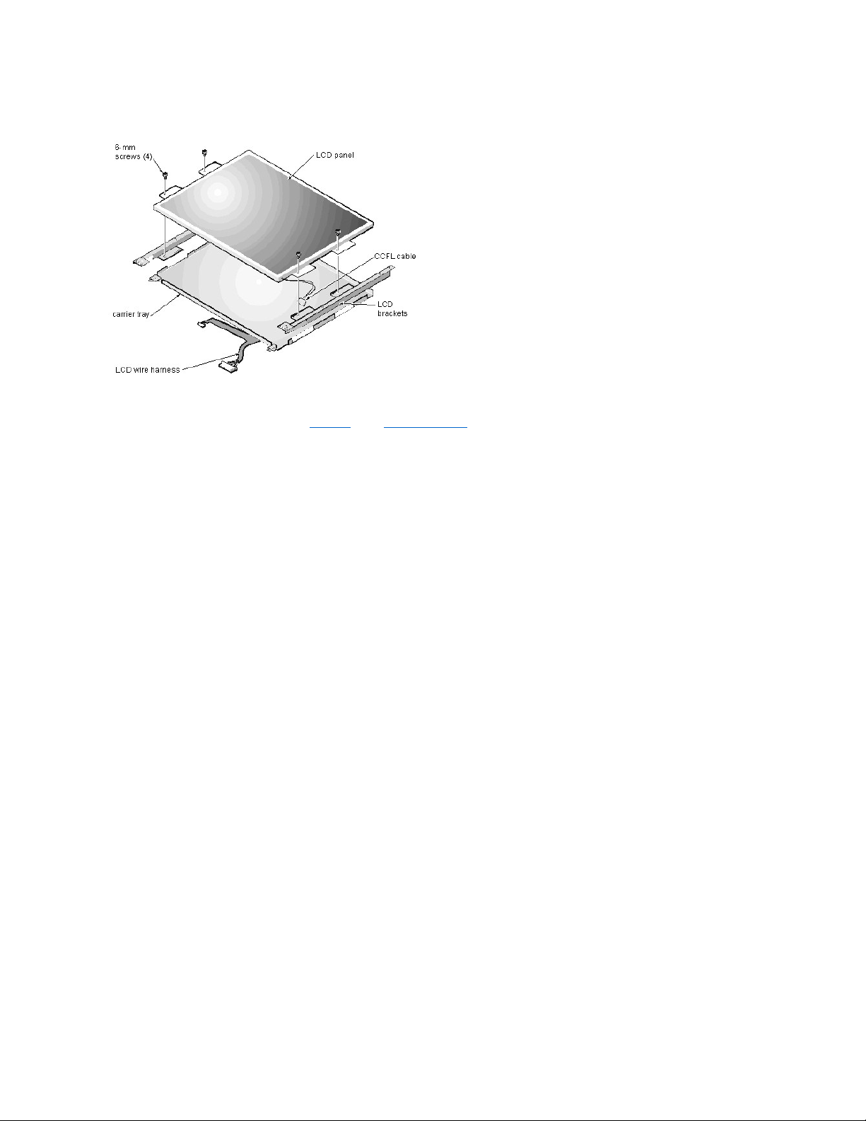
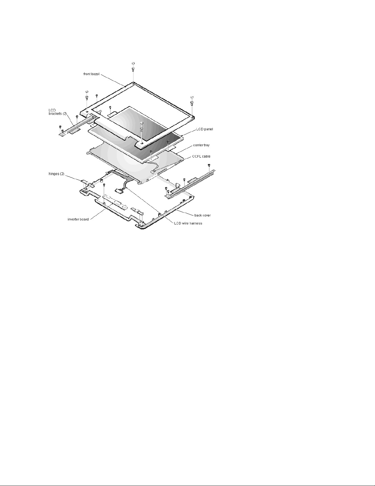
13.3-InchLCDBracketsandCarrierTrayRemoval:Dell™Inspiron™7000
This procedure assumes that you have removed the front bezel and the 13.3-inch LCD panel. To remove the brackets from the LCD panel, follow these steps:
1. Detach the LCD wire harness from connector CN1 on the top left side of the inverter board.
2. Remove the (4) 6-mm screws from the sides of the mounting brackets.
3. Remove the brackets from the LCD panel.
To remove the 13.3-inch LCD panel from the carrier tray, follow these steps:
1. Remove any Kapton tape covering the CCFL cable.
2. Gently pull the cable out of its connector.
3. Remove any Kapton tape from the LCD wire harness.
4. Disconnect the LCD wire harness from the LCD panel.
5. Lift the LCD panel out of carrier tray.
NOTICE: The metal on the carrier tray is sharp. Be careful not to cut yourself.
Page 3
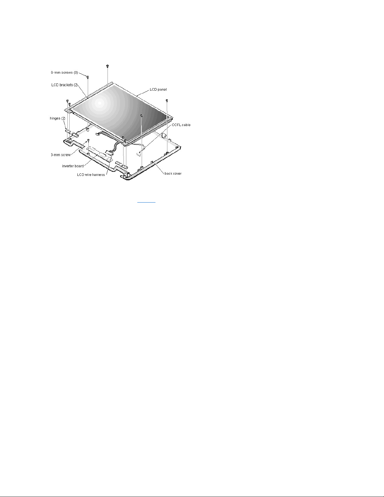
13.3-InchLCDPanelRemoval:Dell™Inspiron™7000
This procedure assumes that you have removed the front bezel. Follow these steps to remove the 13.3-inch LCD panel:
1. Remove the (8) 6-mm screws that secure the left and right LCD brackets to the front plastic cover.
2. Detach the LCD wire harness from connector CN2 on the right side of inverter board.
3. If present, carefully remove the grounding tape between the inverter board and LCD panel.
4. Loosen the 3-mm screw securing the inverter board.
5. Lift the LCD panel, LCD brackets, and carrier tray, as a unit, out of the back cover.
Rotate upward from the bottom of the panel because the top slides underneath the plastic hooks.
6. Remove the hinges, which were previously held in place by pressure and screws.
To remove the inverter board, follow these steps:
1. Remove the 3-mm screw securing the inverter board to the back cover.
2. If you have not removed the LCD panel, disconnect the LCD wire harness from connectors CN1 and CN2 on the inverter board.
3. Remove the inverter board from the back cover.
Page 4
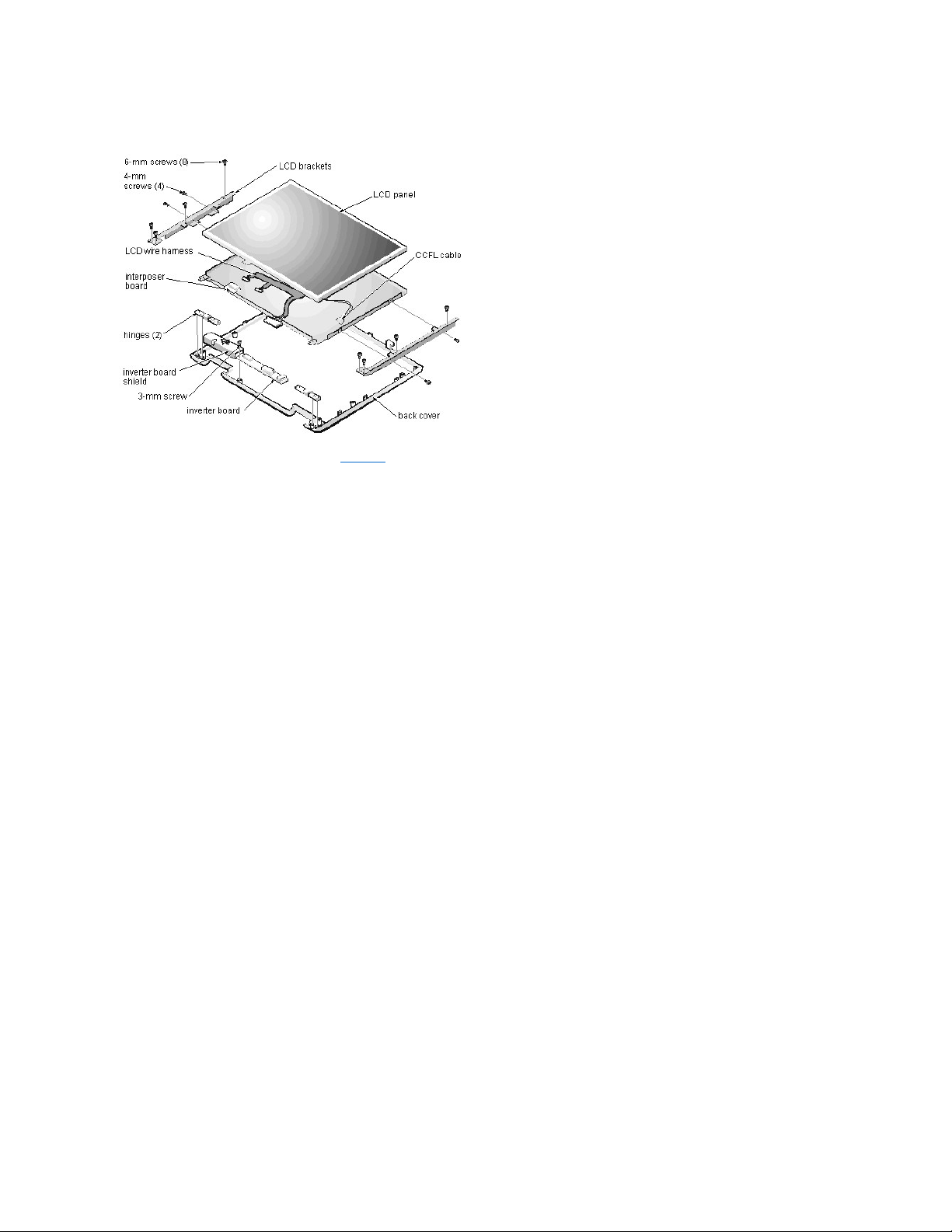
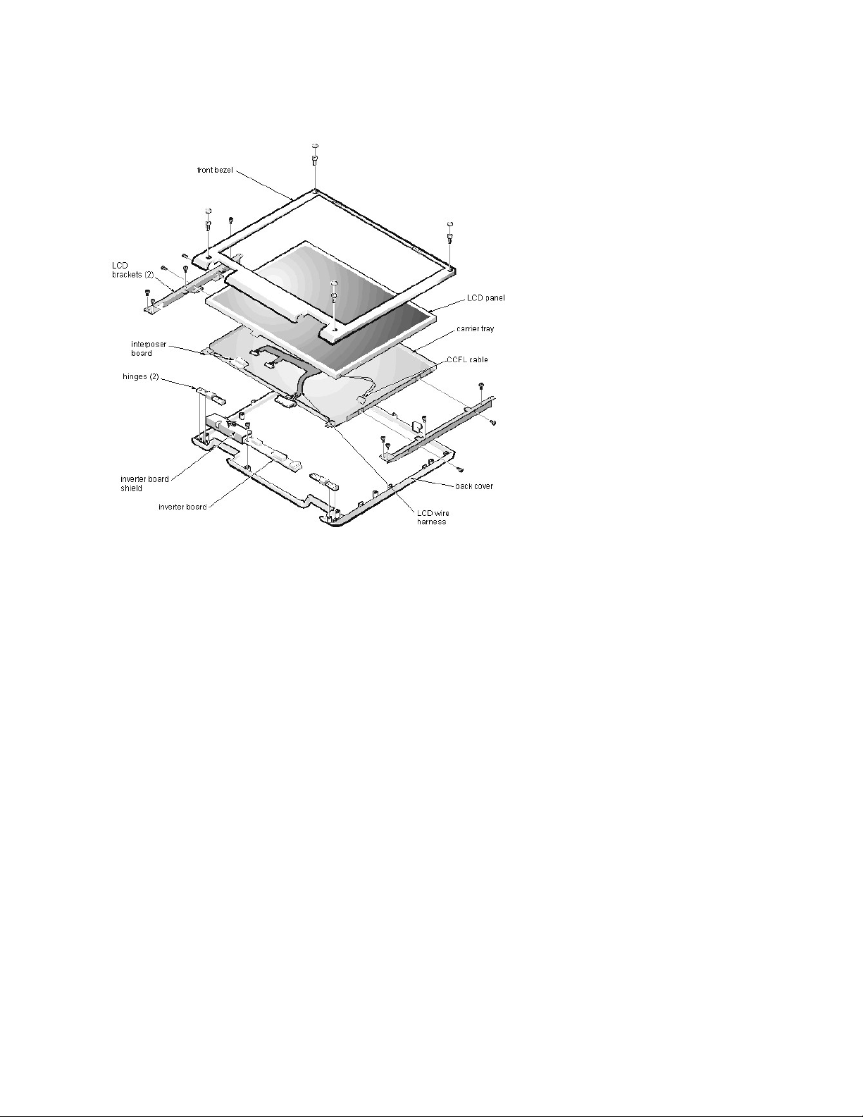
14.1-InchLCDPanel,Brackets,andCarrierTrayRemoval:Dell™Inspiron™7000
This procedure assumes that you have removed the front bezel. Follow these steps to remove the 14.1-inch LCD panel:
1. Remove the (8) 6-mm screws that secure the left and right LCD brackets to the front plastic cover.
2. Detach the CCFL cable from connector CN2 on the right side of inverter board.
3. Carefully remove the grounding tape between the inverter board and LCD panel.
4. Remove the 3-mm screw securing the inverter board, and unsnap the inverter board from the back cover.
5. Lift the LCD panel, LCD brackets, and inverter board as one unit out of the back cover.
Rotate upward from the bottom of the panel because the top slides underneath the plastic hooks.
6. Remove the hinges, which were previously held in place by pressure and screws.
To remove the LCD brackets from the LCD panel, follow these steps:
1. Remove the (4) 4-mm screws from the sides of the LCD brackets.
2. Remove the brackets from the LCD panel.
To remove the LCD panel from the carrier tray, follow these steps:
1. Lift the inverter board shield, pull it slightly away from the panel to expose the cabling, and detach the LCD wire harness from connector CN1 on the inverter
board.
2. Remove any Kapton tape covering the CCFL cable on the back of the LCD.
3. Gently pull the interposer board off the connector to the LCD panel.
4. Lift the LCD panel up and remove any tape between the LCD wire harness and the carrier tray.
5. Disconnect the LCD wire harness from the LCD panel.
6. Lift the LCD panel out of the carrier tray.
7. Disconnect the LCD wire harness from the LCD panel.
NOTICE: The metal on the carrier tray is sharp. Be careful not to cut yourself.
Page 5

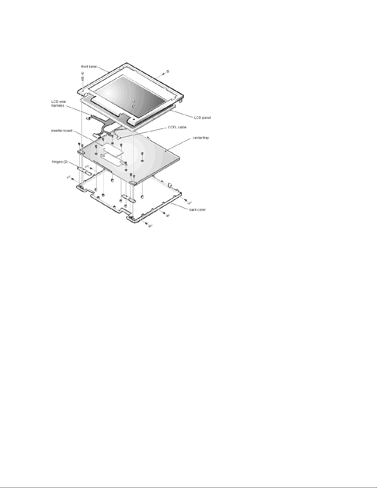
15-inchLCDPanelRemoval:Dell™Inspiron™7000
To remove the 15-inch LCD panel, perform the following steps:
1. Turn the computer over and remove the 4 screws from the bottom of the computer.
2. Turn the computer back over and open the display.
3. Remove the plastic hinge covers.
4. Insert a small flat-blade screwdriver or a similar plastic tool along the top-right edge of the keyboard, above the row of function keys. Working from right to left,
free the keyboard by prying it toward the front of the unit. When free, lift the top of the keyboard slightly to clear the palmrest assembly.
5. Remove the keyboard bracket (located in the upper-right corner of the keyboard).
6. Remove the four screws that secure the two hinges.
7. Unplug the LCD wire harness and lift the assembly off the computer base.
To remove the front bezel, follow these steps:
1. Remove the two rubber screw covers and screws on the LCD near the hinge. Remove the remaining three plastic screw covers and screws, one on either side
and one in the front.
2. With all screws removed, unsnap the front bezel from the back cover and remove the bezel from the assembly.
To remove the LCD panel, hinges, and inverter board, follow these steps:
1. Remove the 4 remaining screw covers and screws on the sides of the LCD.
2. With all screws removed, lift the LCD panel out and disconnect the CCFL wire from the inverter board.
3. Detach the LCD wire harness from connector CN2 on the right side of the inverter board.
4. Carefully remove the grounding tape between the inverter board and the LCD panel.
5. Remove the two 2.5-mm screws securing the inverter board to the back cover.
6. Remove the inverter board from the back cover.
To reassemble, perform the steps in reverse order.
Page 6
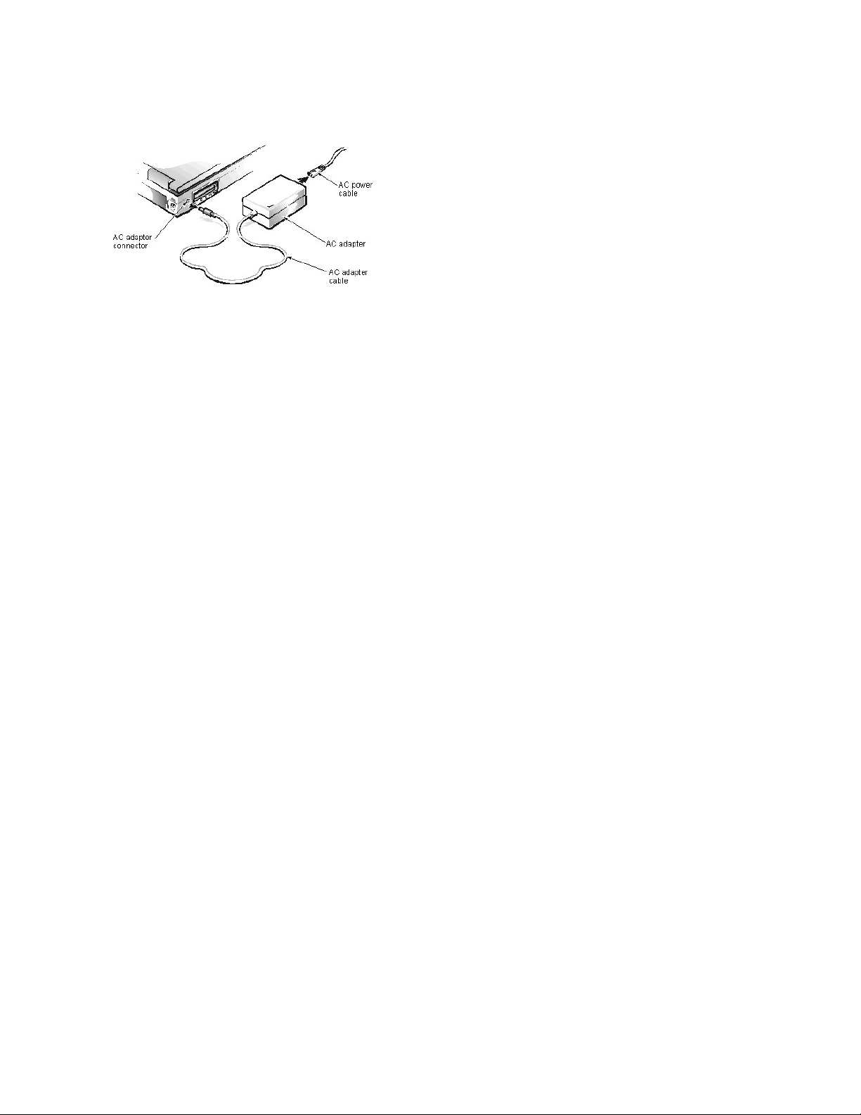
ACAdapter:Dell™Inspiron™7000
Page 7
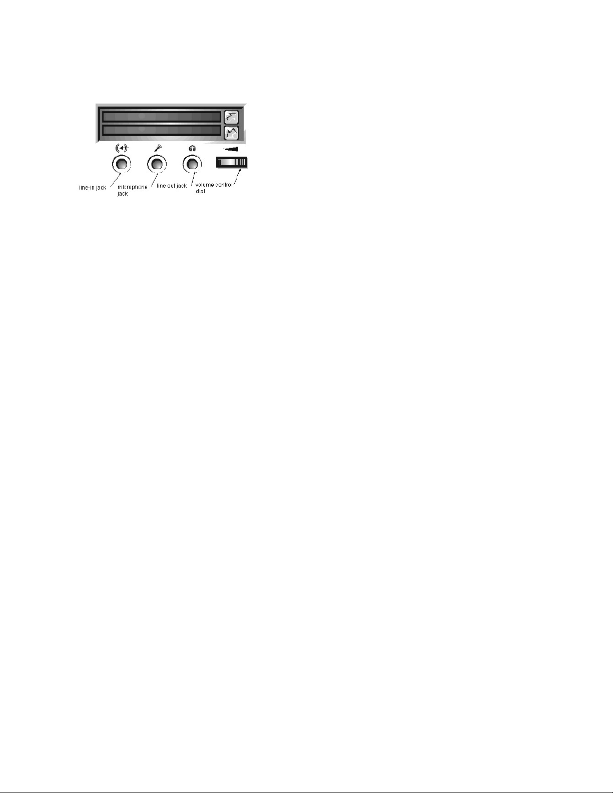
AudioJacks:Dell™Inspiron™7000
Page 8

AudioDevices:Dell™Inspiron™7000
You can connect speakers, a microphone, headphones, and record/playback devices such as cassette players, CD players, and VCRs to the sound jacks on the
computer. Dell recommends using amplified speakers for the best sound.
Connect headphones or speakers to the line-out jack on the far right of the sound jacks. Connect a microphone to the microphone jack in the middle. Connect
record/playback devices such as cassette players, CD players, and VCRs to the line-in jack on the far left.
See your Microsoft® Windows® 98 documentation for the location of sound applications such as mixers and volume control.
You can control the sound coming from the external speakers and from the computer's built-in speakers with the volume control dial. You can also use the keyboard to
adjust the volumes. Press <Fn><Page Down> to lower the volume. Press <Fn><Page Up> to increase the volume. Press <Fn><End> to enable or disable both the
built-in and external speakers.
See Reinstalling Utilities and Drivers for information about reinstalling the audio drivers. The drivers are located on the Dell Inspiron 7000 System Software CD.
NOTE: If no sound comes from the speakers, make sure that the sound is not disabled by pressing <Fn><End> and checking the volume control dial.
Page 9
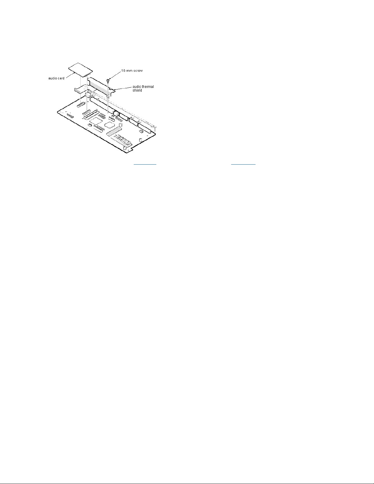
AudioCardandAudioThermalShieldRemoval:Dell™Inspiron™7000
This procedure assumes that you have removed the system board from the plastic case and have removed the PC Card cage from the system board. To remove the
audio card and audio thermal shield, follow these steps:
1. Gently pull the audio card off of connectors JP12 and JP13 on the system board. Do not rock the card to remove it, because this may damage the connectors.
2. Remove the 10-mm screw securing the audio thermal shield, and then remove the shield.
Page 10
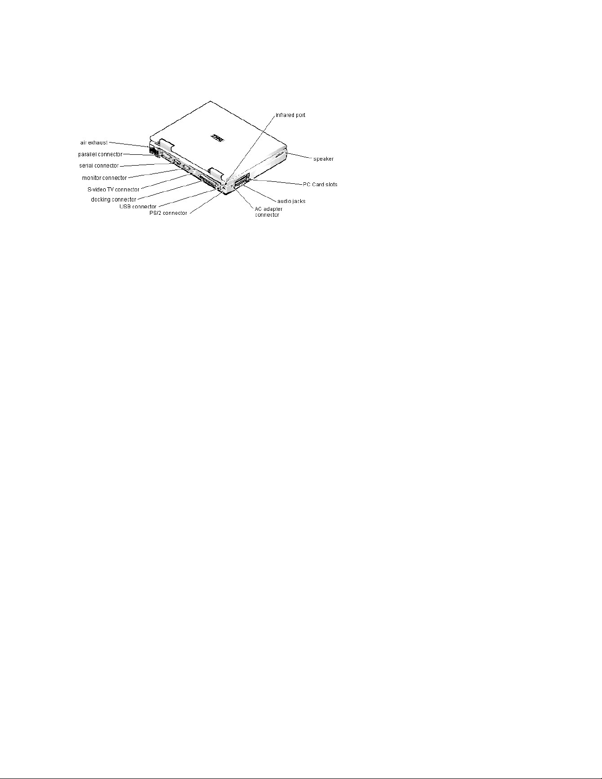
ComponentLocations(BackView):Dell™Inspiron™7000
Page 11
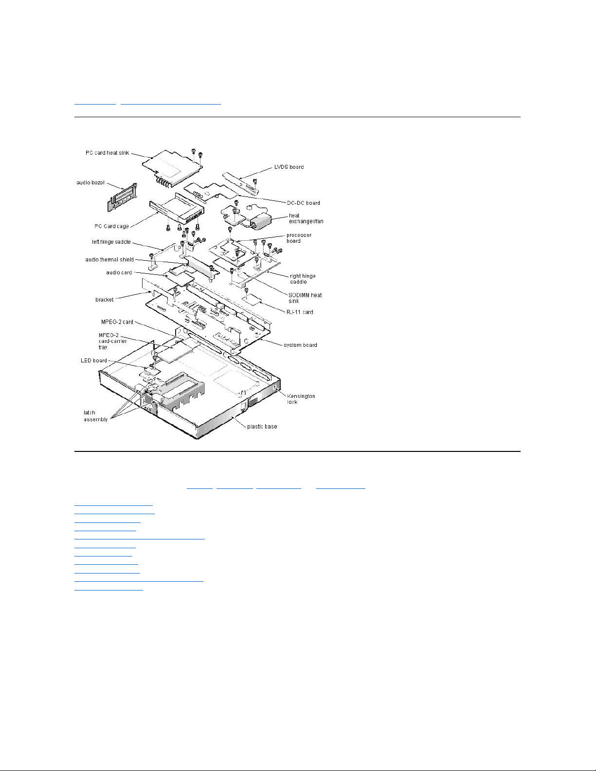
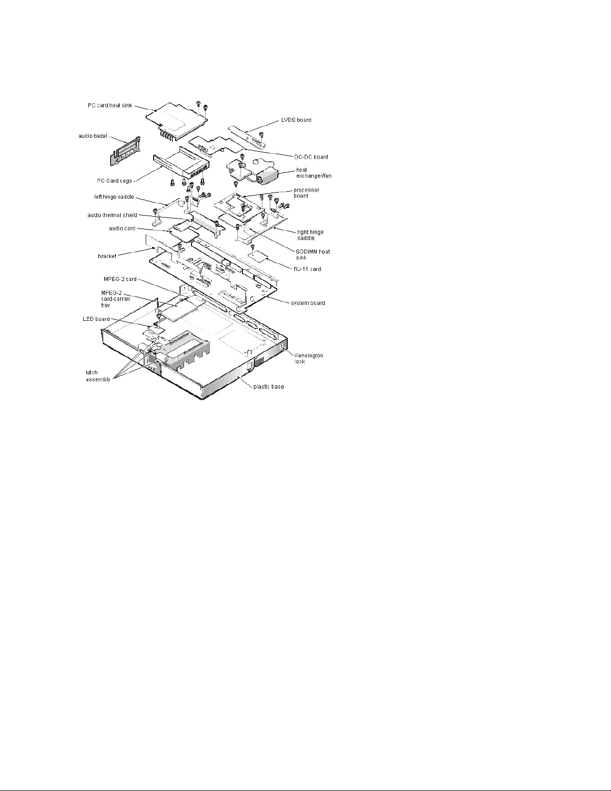
Base Assembly Component Removal:Dell™Inspiron™7000
Base Assembly | Base Assembly Component Removal
Base Assembly
Base Assembly Component Removal
The following procedures assume that the keyboard, thermal shield, display assembly, and palmrest assembly have been removed.
PC Card Heat Sink Removal
Heat Exchanger/Fan Removal
DC-DC Board Removal
LVDS Board Removal
Processor Board and Memory Module Removal
Hinge Saddle Removal
RJ-11 Card Removal
System Board Removal
PC Card Cage Removal
Audio Card and Audio Thermal Shield Removal
Latch Assembly Removal
Page 12
BatteryChargeGauge:Dell™Inspiron™7000
Page 13
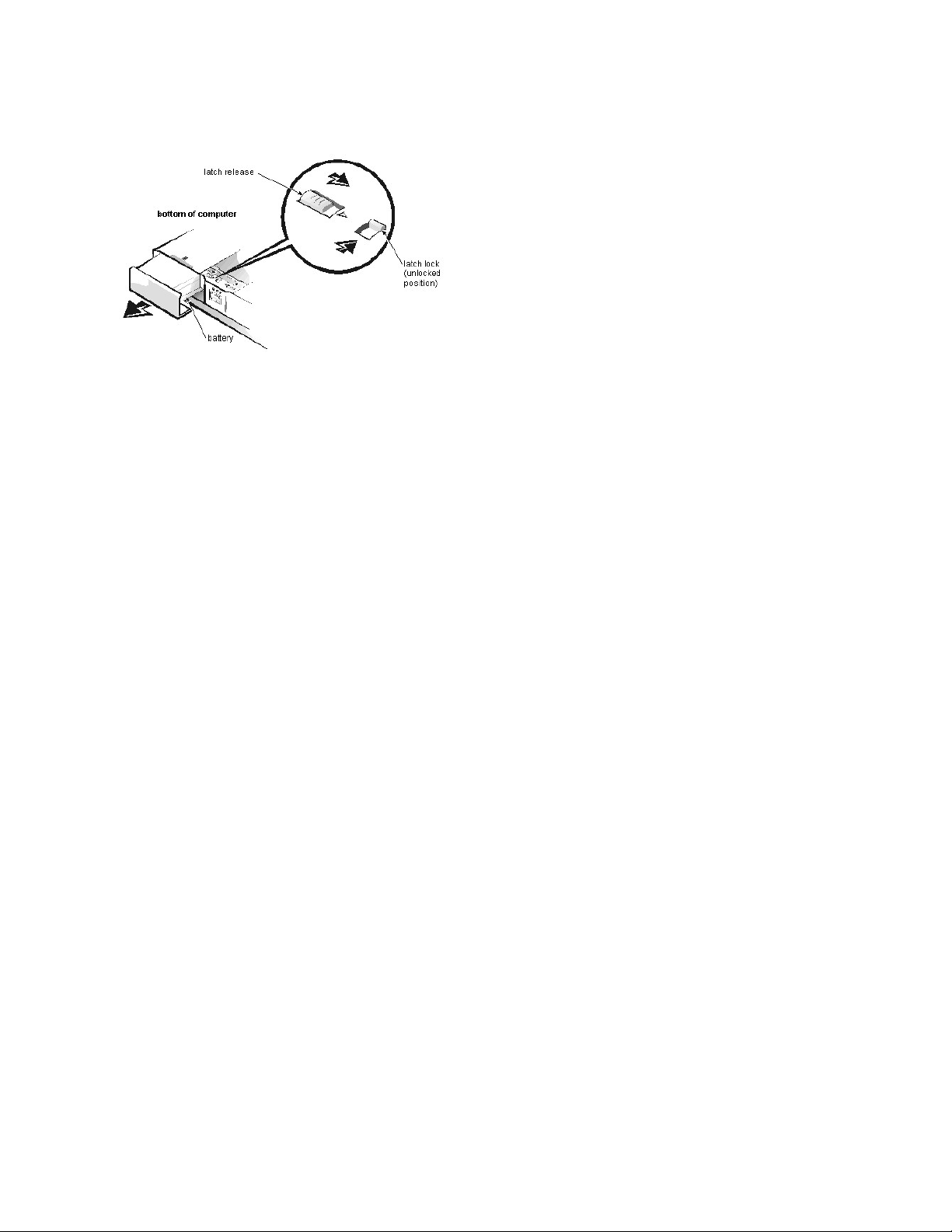
RemovingandInstallingaBattery:Dell™Inspiron™7000
Page 14
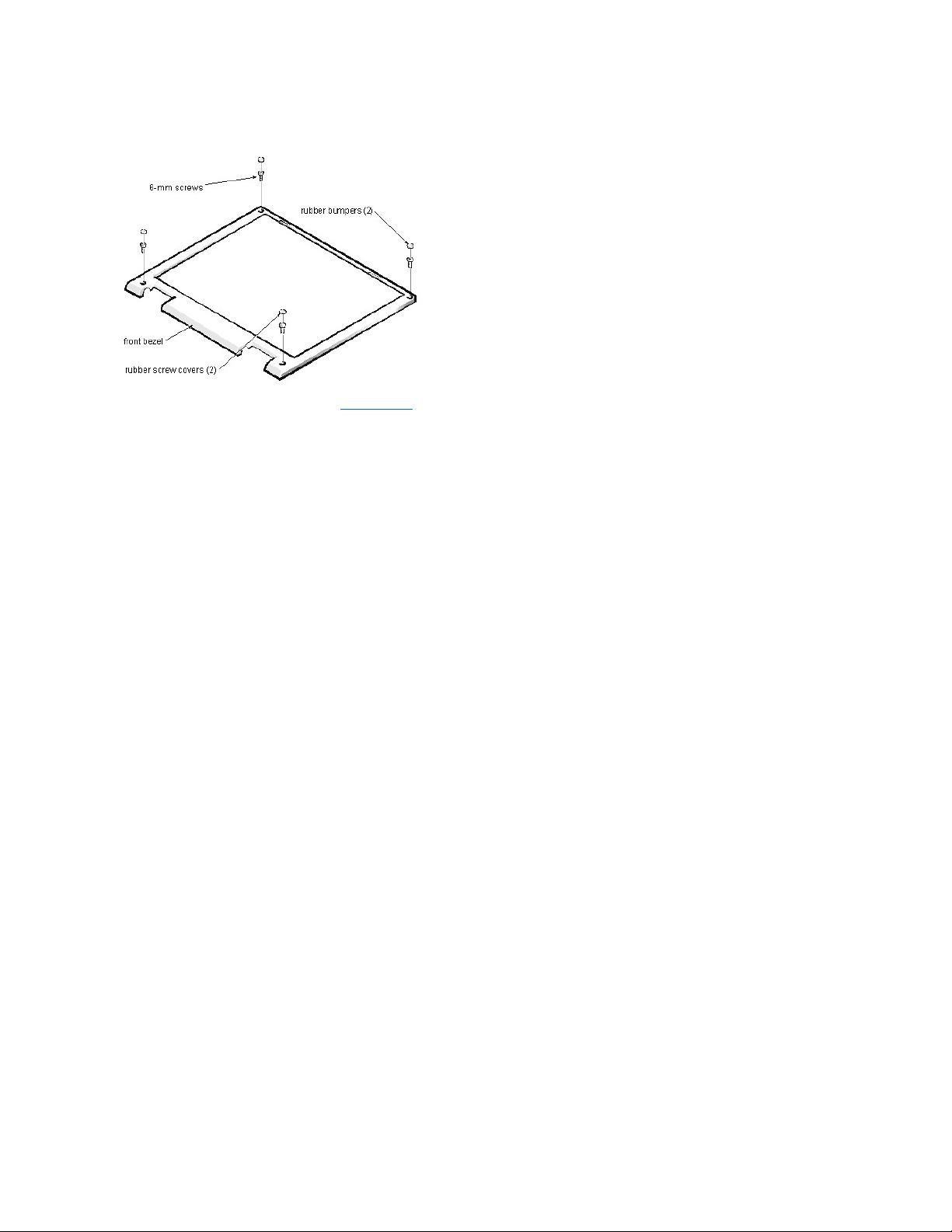
FrontBezelRemoval:Dell™Inspiron™7000
This procedure assumes that you have removed the display assembly from the computer base. To remove the front bezel, follow these steps:
1. Use a dental pick to pry the rubber screw covers off of the bottom 2 screws and the rubber bumpers off of the top 2 screws.
2. Remove the (4) 6-mm screws from the front bezel.
3. Unsnap the front bezel from the back cover and remove it from the assembly.
Carefully insert your fingers between the LCD panel and the bezel. Roll the plastic up slightly to insert your fingers further in, and then lift upward to free the snaps. Start at the
middle bottom and then work around.
When replacing the bezel, ensure that the LCD wire harness is routed correctly through the openings in the back cover and is not pinched.
Page 15
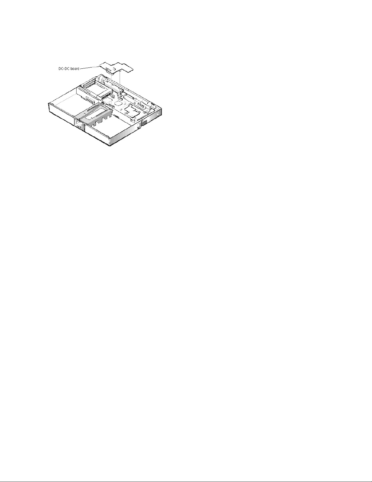
DC-DCBoardRemoval:Dell™Inspiron™7000
To remove the DC-DC board, gently pull the DC-DC board off of connectors JP11 and JP16 on the system board. Do not rock the board to remove it, because this
may damage the connectors.
Page 16
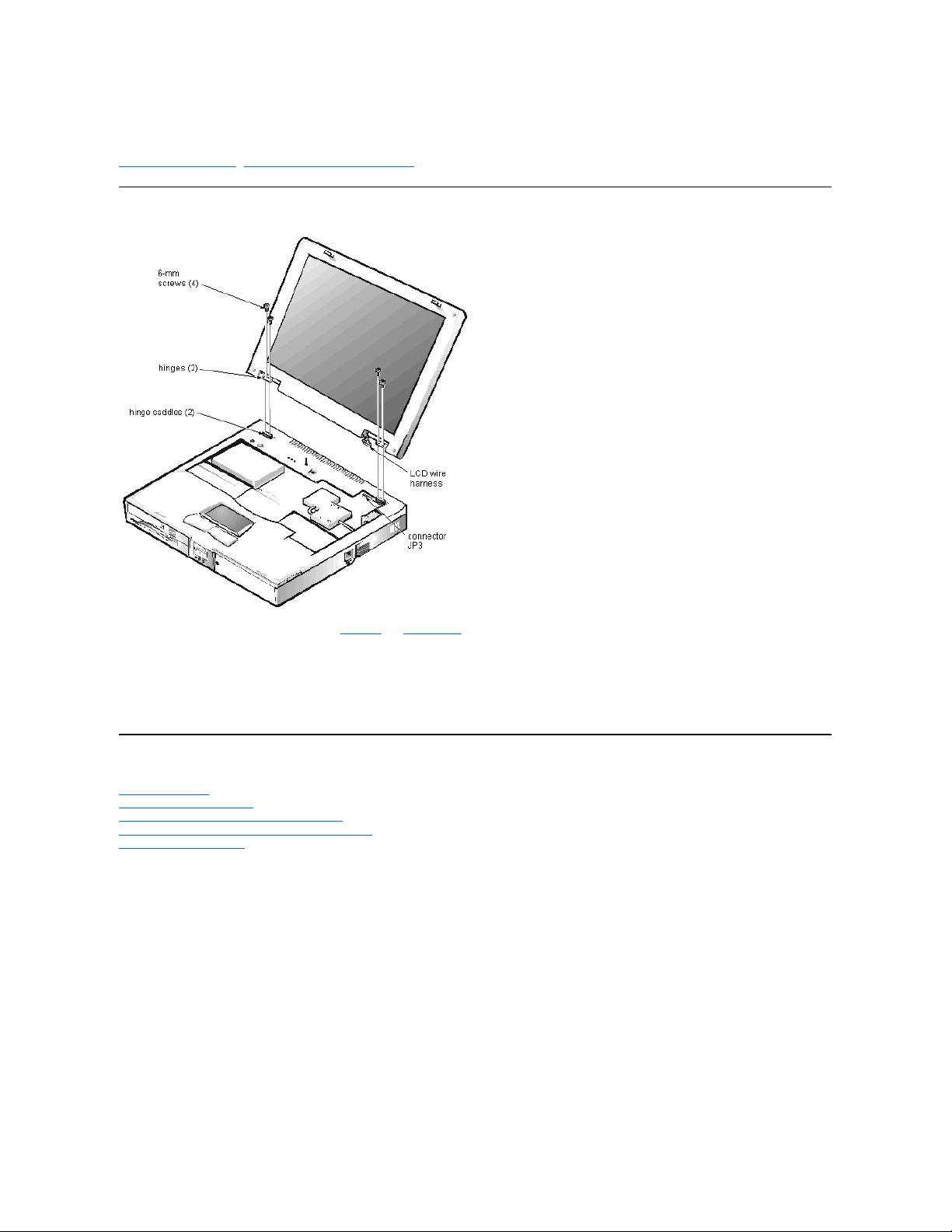
DisplayAssemblyandDisplayAssemblyComponentRemoval:Dell™Inspiron™7000
Display Assembly Removal | Display Assembly Component Removal
Display Assembly Removal
This procedure assumes that you have removed the keyboard and thermal shield. To remove the display assembly from the computer, follow these steps:
1. Disconnect the LCD wire harness from connector JP3.
Use a dental pick or flat-blade screwdriver to pry up each end of the connector to release it.
2. Close the display.
3. Remove the (4) 6-mm screws that secure the 2 hinges.
4. Unlatch the display assembly and lift the assembly off the computer base.
Display Assembly Component Removal
Front Bezel Removal
13.3-Inch LCD Panel Removal
13.3-Inch LCD Brackets and Carrier Tray Removal
14.1-Inch LCD Panel, Brackets and Carrier Tray Removal
15-Inch LCD Panel Removal
Page 17

Back to Contents Page
Documentation:Dell™Inspiron™7000
Printed Documentation | Online Documentation
Printed Documentation
To save PDF files (files with an extension of .pdf) to your hard-disk drive, right-click the document title, click Save Target As in Microsoft® Internet Explorer or
Save Link As in Netscape Navigator, and specify a location on your hard-disk drive.
Right-click only the following links:
Dell Inspiron 7000 Reference and Troubleshooting Guide (.pdf)
Dell Inspiron 7000 Series Installing Drivers and Utilities (Windows 98)(.pdf)
Dell Inspiron 7000 Series Windows NT 4.0 Workstation Installing Drivers and Utilities (.pdf)
Dell Inspiron 7000 Port Replicator User's Guide (.pdf)
Dell Inspiron 7000 Service Manual (.pdf)
Dell Inspiron Systems Setup Guide (.pdf)
Dell Inspiron 7000 Portable Computer Documentation Update (.pdf)
Online Documentation
Downloading the Help and Associated Files
1. Right-click the following link to the popup.ocx file:
popup.ocx
2. Click Save Target As in Microsoft Internet Explorer or Save Link As in Netscape Navigator, and specify c:\windows\system on your hard-disk drive.
3. Click the Start button on the Microsoft Windows® desktop, and then click Run.
4. Type regsvr32 popup.ocx and then press <Enter>.
5. Click OK when the installation is complete.
6. Right-click the following link to the Help file:
Dell Inspiron 7000 Series Help (.chm) (1179 KB)
7. Click Save Target As in Microsoft Internet Explorer or Save Link As in Netscape Navigator, and specify a location on your hard-disk drive.
Viewing the Help File
To view the Help file, perform the following steps:
1. Click the Start button on the Windows desktop, point to Programs, and then click Windows Explorer.
2. Navigate to the directory in which you saved the Help file.
3. Double-click the file (7000help.chm).
Back to Contents Page
You must right-click the link for a portable document format (PDF) file and save the file to your hard-disk drive. Attempting to link directly to
large PDF files causes your system to freeze.
NOTES:PDFfilesrequireAdobe™AcrobatReader,whichcanbedownloadedfromthefromtheAdobeWorldWideWebsiteat:
http://www.adobe.com/acrobat/.
To view a PDF file, launch Acrobat Reader. Click File–> Open and select the PDF file.
Compiled HTML Help files (files with an extension of .chm) require Microsoft Internet Explorer 4.0 or later.
Page 18

ReinstallingUtilitiesandDrivers:Dell™Inspiron™7000
To reinstall utilities and drivers on a computer running the Microsoft® Windows® 98 operating system, use the program diskette set from Dell or the backup diskettes
that you made after receiving the computer.
To reinstall the system software, you need the following items:
l The Microsoft Windows 98 CD
l The Microsoft Boot Disk Windows 98 Series diskette
l The Dell Inspiron 7000 System Software CD
Reinstalling Video Drivers | Reinstalling Touch Pad Drivers | Reinstalling Audio Drivers | Reinstalling Internal Modem Drivers | Reinstalling DVD-ROM Decoder
Drivers | Creating the Save-to-Disk Suspend File | Reinstalling the System User's Guide
Reinstalling Video Drivers
Video drivers control features such as screen resolution and the number of screen colors.
To reinstall the video drivers, perform the following steps:
1. Save your work in all open application programs, because you will need to restart your computer at the end of this procedure to complete the installation.
2. Insert the Dell Inspiron 7000 System Software CD into the CD-ROM or DVD-ROM drive.
3. Click the Start button, and then click Run.
4. In the Run dialog box, type x:\video\setup.exe, where x is the letter designation for the CD-ROM drive.
5. Click OK.
6. When the ATI Setup window appears, click Finish.
The video files are copied to your hard-disk drive.
7. When prompted, click Yes to restart the computer.
Reinstalling Touch Pad Drivers
Touch pad drivers and associated utilities allow you to customize the operation of your touch pad and cursor features. To reinstall the touch pad drivers, perform the
following steps:
1. Save your work in all open application programs, because you will need to restart your computer at the end of this procedure to complete the installation.
2. Insert the Dell Inspiron 7000 System Software CD into the CD-ROM or DVD-ROM drive.
3. Click the Start button, and then click Run.
4. In the Run dialog box, type x:\touchpad\setup.exe, where x is the letter designation for the CD-ROM drive.
5. Click OK.
6. At the Welcome screen, click Next>.
7. At the Choose Destination Location window, click Next>.
8. At the Start Copying Files window, click Next>.
The touch pad files are copied to your hard-disk drive.
9. At the Setup Complete window, click Yes, I want to restart my computer now, and then click Finish.
Reinstalling Audio Drivers
Audio drivers allow you to customize the sound features of your computer. To reinstall the audio drivers, perform the following steps:
1. Save your work in all open application programs, because you will need to restart your computer at the end of this procedure to complete the installation.
2. Insert the Dell Inspiron 7000 System Software CD into the CD-ROM or DVD-ROM drive.
3. Click the Start button, and then click Run.
4. In the Run dialog box, type x:\audio\setup.exe where x is the letter designation for the CD-ROM drive.
5. Click OK.
6. At the Main menu, click Upgrade Drivers and then click Next>.
The audio files are copied to your hard-disk drive.
7. When prompted, click Yes, I want to restart my computer now, and then click Finish.
8. After Windows 98 restarts, the New Hardware Wizard appears.
9. Click Next>.
10. At the next screen, click Search for the best driver for your device, and then click Next>.
11. At the next screen, click Specify a location, and specify the Audio folder on your CD-ROM or DVD-ROM drive.
12. Click Next>.
13. When the driver has been detected, click Next>.
Messages that indicate that files are being copied and driver information is being built appear on your screen.
NOTE: If you need to use extended-video modes, check the documentation that came with the application program to determine if the drivers are
provided. If not, contact the software manufacturer to get the necessary drivers.
Page 19

14. When prompted, click Finish.
The New hardware found window appears, the driver is installed, and the installation is completed.
Reinstalling Internal Modem Drivers
Modem drivers allow you to customize the operation of your optional internal modem. If your computer has an internal modem, perform the following steps to install
the drivers:
1. Save your work in all open application programs, because you will need to restart your computer at the end of this procedure to complete the installation.
2. Insert the Dell Inspiron 7000 System Software CD into the CD-ROM or DVD-ROM drive.
3. Click the Start button, and then click Run.
4. In the Run dialog box, type x:\modem\setup.exe, where x is the letter designation for the CD-ROM drive.
5. Click OK.
6. At the Welcome Screen, click Next>.
The internal modem files are copied to your hard-disk drive.
7. At the Setup Complete window, click Yes, I want to restart my computer now, and then click Finish.
The New hardware found window appears and states that the system has detected the new hardware.
8. Click Remove and then click OK.
Reinstalling DVD-ROM Decoder Drivers
DVD-ROM decoder drivers allow the MPEG decoder on your optional DVD-ROM drive to decode MPEG files, such as DVD movies. If your computer has a
DVD-ROM drive, perform the following steps to install the drivers:
1. Save your work in all open application programs, because you will need to restart your computer at the end of this procedure to complete the installation.
2. Restart your computer.
3. Press <F2> at the Dell logo screen.
The Setup menu window appears.
4. Press <Tab> to highlight System Devices, and verify that the option Internal MPEGii is enabled.
5. Insert the Dell Inspiron 7000 System Software CD into the DVD-ROM drive.
6. At the Welcome screen, click Next>.
7. Click the Start button, and then click Run.
8. In the Run dialog box, type x:\dvd[mpeg]\setup.exe, where x is the letter designation for the CD-ROM drive.
9. Click OK.
Creating the Save-to-Disk Suspend File
If you are installing a new hard-disk drive or if you are rebuilding a hard-disk drive that has corrupted software and you want to be able to use the save-to-disk
suspend mode, you must use the phdisk.exe utility on your System Utilities diskette to create a save-to-disk suspend file. When save-to-disk suspend mode is
activated, all system data is stored in this file.
To create the save-to-disk suspend file, perform the following steps:
1. Insert the Microsoft Boot Disk Windows 98 Series diskette into the diskette drive.
2. Restart the system.
3. When the Microsoft Windows 98 Startup Menu appears, select Start computer with CD-ROM Support and press <Enter>.
4. When the MS-DOS®prompt appears, insert the Dell Inspiron 7000 System Software CD into the CD-ROM or DVD-ROM drive.
5. At the MS-DOS prompt, type d: and press <Enter>, where d is the drive letter for your CD-ROM or DVD-ROM drive.
Your MS-DOS prompt changes from an A:\> to a D:\>, assuming D is the drive letter for your CD-ROM or DVD-ROM drive.
6. Type cd\utility and press <Enter>.
7. Type phdisk /create /file and press <Enter>.
The utility calculates the size of the file, in kilobytes, based on the amount of system memory in your computer, plus 2 MB to handle video memory and additional system
requirements.
8. Follow the instructions on your screen to create the save-to-disk suspend file.
To check the size of the save-to-disk suspend file, at an MS-DOS prompt type phdisk /info and press <Enter>.
If you need to delete the save-to-disk suspend file, at an MS-DOS prompt type phdisk /delete /file and press <Enter>.
Reinstalling the System User’s Guide
If needed, you can download the Dell Inspiron 7000 User’s Guide from Dell’s World Wide Web site at http://www.dell.com/:
1. Click the Support icon.
The Dell Support main menu appears.
NOTE: Make sure that there is a space between phdisk /create and /file.
Page 20

2. Click Troubleshoot Your Dell System, and then locate the link to the Inspiron page.
3. Select 7000.
4. Click Technical Information, and then click Documentation.
5. Click System User’s Guide.
6. When prompted, save the file to your hard-disk drive.
Page 21

Reinstalling Utilities and Drivers for Microsoft®Windows®98:Dell™Inspiron™7000
Overview | Reinstalling Video Drivers | Reinstalling Touch Pad Drivers | Reinstalling Audio Drivers | Reinstalling Internal Modem Drivers | Reinstalling DVD-ROM
Decoder Drivers | Reinstalling the Hardware DVD Decoder Driver | Reinstalling Softex BayManager Software | Creating the Save-to-Disk Suspend File | Reinstalling
the System Help File
Overview
To reinstall utilities and drivers on a computer running the Microsoft Windows 98 operating system, use the program diskette set from Dell or the backup diskettes that
you made after receiving the computer.
To reinstall the system software, you need the following items:
l The Microsoft Windows 98 CD
l The Microsoft Boot Disk Windows 98 Series diskette
l The Dell Inspiron 7000 System Software CD
Reinstalling Video Drivers
Video drivers control features such as screen resolution and the number of screen colors.
To reinstall the video drivers, perform the following steps:
1. Save your work in all open application programs, because you will need to restart your computer at the end of this procedure to complete the installation.
2. Insert the Dell Inspiron 7000 System Software CD into the CD-ROM or DVD-ROM drive.
3. If the Welcome to Windows 98 screen appears, click the x in the upper-right corner of the screen to close it and continue with the installation.
4. Click the Start button, and then click Run.
5. In the Run dialog box, type x:\video\setup.exe, where x is the letter designation for the CD-ROM or DVD-ROM drive.
The CD-ROM or DVD-ROM drive letter is usually D.
6. Click OK.
7. At the Welcome screen, click Next >.
8. At the Main Menu, the Upgrade Drivers radio button is selected. Click Next >.
9. The video files are copied to your hard-disk drive.
Reinstalling Touch Pad Drivers
Touch pad drivers and associated utilities allow you to customize the operation of your touch pad and cursor features. To reinstall the touch pad drivers, perform the
following steps:
1. Save your work in all open application programs, because you will need to restart your computer at the end of this procedure to complete the installation.
2. Insert the Dell Inspiron 7000 System Software CD into the CD-ROM or DVD-ROM drive.
3. If the Welcome to Windows 98 screen appears, click the x in the upper-right corner of the screen to close it and continue with the installation.
4. Click the Start button, and then click Run.
5. In the Run dialog box, type x:\touchpad\setup.exe, where x is the letter designation for the CD-ROM or DVD-ROM drive.
The CD-ROM or DVD-ROM drive letter is usually D.
6. Click OK.
7. At the Welcome screen, click Next>.
At the Choose Destination Location window, click Next>.
8. At the Start Copying Files window, click Next>.
9.
The touch pad files are copied to your hard-disk drive.
10. At the Setup Complete window, click Yes, I want to restart my computer now, and then click Finish.
11.
The Information about your TouchPad window appears. If you do no want this window to appear each time you start the computer, uncheck the box that says Show this message
the next time Windows starts. Then click Close.
Reinstalling Audio Drivers
Audio drivers allow you to customize the sound features of your computer. To reinstall the audio drivers, perform the following steps:
1. Save your work in all open application programs, because you will need to restart your computer at the end of this procedure to complete the installation.
NOTE: If you need to use extended-video modes, check the documentation that came with the application program to determine if the drivers are
provided. If not, contact the software manufacturer to get the necessary drivers.
Page 22

2. Insert the Dell Inspiron 7000 System Software CD into the CD-ROM or DVD-ROM drive.
3. If the Welcome to Windows 98 screen appears, click the x in the upper-right corner of the screen to close it and continue with the installation.
4. Click the Start button, and then click Run.
5. In the Run dialog box, type x:\audio\setup.exe where x is the letter designation for the CD-ROM or DVD-ROM drive.
The CD-ROM or DVD-ROM drive letter is usually D.
6. Click OK.
7. At theWelcome screen, click Next >.
8. At the Main menu, click Upgrade Drivers and then click Next >.
The audio files are copied to your hard-disk drive.
9. When prompted, be sure that the Yes, I want to restart my computer now radio button is selected, and then click Finish.
After Windows 98 restarts, the New Hardware Wizard appears.
10. Click Next>.
11. At the next screen, be sure that theSearch for the best driver for your device (Recommended) radio button is selected and then click Next >.
12. When the Add New Hardware Wizard window appears, deselect Floppy Disk Drives and select Specify a Location.
13. Type d:\audio in the Path Location field and then click Next >.
14. When the driver has been detected, click Next >.
15.
Messages that indicate that files are being copied and driver information is being built appear on your screen.
16. When prompted, click Finish.
17.
The New Hardware Found window appears, the driver is installed, and the installation is completed.
Reinstalling Internal Modem Drivers
Modem drivers allow you to customize the operation of your optional internal modem. If your computer has an internal modem, perform the following steps to install
the drivers:
1. Save your work in all open application programs, because you will need to restart your computer at the end of this procedure to complete the installation.
2. Insert the Dell Inspiron 7000 System Software CD into the CD-ROM or DVD-ROM drive.
3. If the Welcome to Windows 98 screen appears, click the x in the upper-right corner of the screen to close it and continue with the installation.
4. Click the Start button, and then click Run.
5. In the Run dialog box, type x:\modem\setup.exe, where x is the letter designation for the CD-ROM or DVD-ROM drive.
The CD-ROM or DVD-ROM drive letter is usually D.
6. Click OK.
7. At the Welcome Screen, click Next>.
The internal modem files are copied to your hard-disk drive.
8. At the Setup Complete window, click Yes, I want to restart my computer now, and then click Finish.
The New hardware found window appears and states that the system has detected the new hardware.
9. Click Remove and then click OK.
Reinstalling DVD-ROM Decoder Drivers
DVD-ROM decoder drivers allow the Moving Pictures Experts Group (MPEG) decoder on your optional DVD-ROM drive to decode MPEG files, such as DVD
movies. If your computer has a DVD-ROM drive, perform the following steps to install the drivers:
1. Save your work in all open application programs, because you will need to restart your computer at the end of this procedure to complete the installation.
2. Restart your computer.
3. Press <F2> at the Dell logo screen.
The Setup menu window appears.
4. Press the right-arrow key to select the System Devices menu.
If the Internal MPEG II option appears on the System Devices menu, make sure the option is enabled. Then press <F10> to exit the Setup program. Proceed to the next subsection,
“Installing the Hardware DVD Decoder Driver.”
If the Internal MPEG II option does not appear on the System Devices menu, see the section on installing the software DVD decoder driver in the document titled Installing a DVD-
ROM Drive and Software DVD Decoder Driver that accompanied your Dell Inspiron 7000 Series System Software CD.
Reinstalling the Hardware DVD Decoder Driver
To install the hardware DVD decoder driver, perform the following steps:
1. If the Welcome to Windows 98 screen appears, click the x in the upper-right corner of the screen to close it and continue with the installation.
2. Insert the Dell Inspiron 7000 Series System Software CD into the DVD-ROM drive.
3. Click the Start button, and then click Run.
4. In the Run dialog box, type x:\hwdvd\setup.exe, where x is the DVD-ROM drive letter.
The CD-ROM or DVD-ROM drive letter is usually D.
5. Click OK.
6. The Welcome window appears. Click Next>.
7. The Software License Agreement window appears. Click Yes to accept the terms of the agreement.
8. At the Choose Destination Location screen, click Next>.
9. At the Start Copying Files screen, click Next>.
Page 23

10. At the Setup Complete screen, be sure that the Yes , I want to restart my computer now radio button is selected, and then click Finish.
The first time you play a DVD after installing this driver, you may be prompted to change the region setting.
Reinstalling Softex BayManager Software
The Softex BayManager software allows you to remove and install devices without turning off your system. To install BayManager, perform the following steps:
1. Insert the Dell Inspiron 7000 Series System Software CD into the CD-ROM or DVD-ROM drive.
2. Double-click the My Computer icon, and then double-click the CD-ROM or DVD-ROM icon.
3. Double-click the BayMgr folder.
4. Double-click setup.exe.
5. At the Welcome screen, click Next.
An InstallShield message indicates that the files are being copied.
6. At the Setup Complete window, click Yes, I want to restart my computer now, and click Finish.
The system restarts.
7. Remove the Dell Inspiron 7000 Series System Software CD from the drive.
After your computer restarts, a BayManager icon appears in the icon tray at the right of the taskbar.
Creating the Save-to-Disk Suspend File
If you are installing a new hard-disk drive or if you are rebuilding a hard-disk drive that has corrupted software and you want to be able to use the save-to-disk
suspend mode, you must use the phdisk.exe utility on your System Utilities diskette to create a save-to-disk suspend file. When save-to-disk suspend mode is
activated, all system data is stored in this file.
To create the save-to-disk suspend file, perform the following steps:
1. Insert the Microsoft Boot Disk Windows 98 Series diskette into the diskette drive.
2. Restart the system.
3. When the Microsoft Windows 98 Startup Menu appears, select Start computer with CD-ROM Support and press <Enter>.
4. When the MS-DOS®prompt appears, insert the Dell Inspiron 7000 Series System Software CD into the CD-ROM or DVD-ROM drive.
5. When the A:\> prompt appears on the screen, insert the Dell Inspiron 7000 Series System Software CD into your CD-ROM or DVD-ROM drive.
6. At the A:\> prompt, type the drive letter for your CD-ROM or DVD-ROM drive, and press <Enter>.
The CD-ROM or DVD-ROM drive letter is usually D.
7. Type cd\utility and press <Enter>.
8. Type phdisk /create /file and press <Enter>.
The utility calculates the size of the file, in kilobytes, based on the amount of system memory in your computer, plus 2 MB to handle video memory and additional system
requirements.
9. Follow the instructions on your screen to create the save-to-disk suspend file.
To check the size of the save-to-disk suspend file, at an MS-DOS prompt type phdisk /info and press <Enter>.
10.
If you need to delete the save-to-disk suspend file, at an MS-DOS prompt type phdisk /delete /file and press <Enter>.
11. Remove the Microsoft Boot Disk Windows 98 Series diskette, and press <Ctrl><Alt><Del> to restart the system.
Reinstalling the System Help File
If needed, you can download the Dell Inspiron 7000 Series Help File from Dell’s World Wide Web site at http://www.dell.com/:
1. Click the Support icon.
The Dell Support main menu appears.
2. Click Support Your Dell, and then click Inspiron Notebook.
3. Click 7000.
4. Click Documentation.
5. Click Online Documentation, and follow the instructions provided to download and view the Help file.
NOTE: To play MPEG - 2 clips, you must install Microsoft DirectX®6.X and MediaPlayer 6.X. You can download this file at:
http://www.microsoft.com/directx and http://www.microsoft.com/windows/mediaplayer.
NOTE: Make sure a space is between phdisk /create and /file.
Page 24

Reinstalling Utilities and Drivers for Microsoft®Windows NT®: Dell™Inspiron™7000
Overview | Reinstalling Video Drivers | Reinstalling Touch Pad Drivers | Reinstalling Audio Drivers | Reinstalling Internal Modem Drivers| Reinstalling the System Help
File
Overview
To reinstall utilities and drivers on a computer running the Microsoft Windows NT operating system, use the program diskette set from Dell or the backup diskettes that
you made after receiving the computer.
To reinstall the system software, you need the following items:
l Microsoft Windows NT 4.0 CD
l Microsoft Windows NT 4.0 Service Pack 4 CD
l Dell Inspiron 7000 Windows NT 4.0 Workstation System Software CD
l CD-ROM drive (installed)
l One formatted diskette
Reinstalling Video Drivers
Video drivers control features such as screen resolution and the number of screen colors.
To reinstall the video drivers, perform the following steps:
1. Log on as Administrator.
2. Insert the Dell Inspiron 7000 Windows NT 4.0 Workstation System Software CD into the CD-ROM drive.
3. Double-click the My Computer icon, and then double-click Control Panel.
4. In the Control Panel window, double-click the Display icon.
5. In the Display Properties window, click the Settings tab and click Display Type.
6. In the Adapter Type area, click Change.
7. In the Change Display dialog box, click Have Disk.
8. In the Install From Disk dialog box, type x.:\video, where x is the drive letter of the CD-ROM drive.
9. Click OK.
A list of devices supported by this driver appears.
10. Highlight ATI 3d RAGE MOBILITY PAGP, and then click OK.
11. Click Yes when the third-party drivers message appears.
The files are copied to the hard-disk drive.
A message appears stating that the drivers were successfully installed.
12. Click OK.
13. Click Close to close the Display Type dialog box.
14. Click Close to close the Display Properties dialog box.
15. When prompted, click Yes to restart your computer.
Reinstalling Touch Pad Drivers
Touch pad drivers and associated utilities allow you to customize the operation of your touch-pad driver controls features such as touch pad and mouse functions,
scrolling, touch features, and sensitivity. To reinstall the touch pad drivers, perform the following steps:
1. Log on as Administrator.
2. Insert the Dell Inspiron 7000 Windows NT 4.0 Workstation System Software CD into the CD-ROM drive.
3. Double-click the My Computer icon, and then double-click the CD-ROM drive icon.
4. Double-click the Touch pad folder.
5. Double-click Setup.
6. In the Welcome window, click Next>.
7. In the Important Information window, click Next>.
Another Important Information window appears recommending you create or update an emergency repair diskette before you install the Synaptics Touch Pad driver.
8. Ensure that the Run the Emergency Repair Disk utility before installing check box is selected, and then click Next >.
9. Click Next> to install the files in the default directory.
10. Click Next> to begin copying the files.
11. When prompted to create an emergency repair diskette, click Yes.
12. Label a blank diskette “Emergency Repair Diskette,” insert it into the diskette drive, and then click OK.
NOTE: Select the appropriate language.
NOTE: After the computer restarts, you may change the video resolution. See the following section, “Changing Video Resolution.”
Page 25

13. Click OK at the dialog box regarding sensitive information.
14. After the appropriate files are copied onto the hard-disk drive and the emergency repair diskette is created, remove the Emergency Repair Diskette and select
Yes, I want to restart my computer now.
Do not remove the Dell Inspiron 7000 Windows NT 4.0 Workstation System Software CD.
15. Click Finish to exit the installation and restart your computer.
Reinstalling Audio Drivers
Audio drivers allow you to customize the sound features of your computer. To reinstall the audio drivers, perform the following steps:
1. Log on as Administrator.
2. Insert the Dell Inspiron 7000 Windows NT 4.0 Workstation System Software CD into the CD-ROM drive.
3. Double-click the My Computer icon and then double-click Control Panel.
4. In the Control Panel window, double-click the Multimedia icon.
5. In the Multimedia Properties window, click the Devices tab.
6. Click Add.
7. In the Add pop-up window, highlight Unlisted or Updated Driver Click OK.
8. Type x:\audio, where x is the drive letter of the CD-ROM drive, and then click OK.
The Add Unlisted or Updated Driver dialog box appears with ESS Audio Driver M2/M2E 4.02.37 highlighted.
9. Click OK.
The required mastro.dll is already on the system. Do you want to use the current driver or
install a new driver?
10. Click OK, and then click OK again.
11. Click Restart Now to restart the computer.
Reinstalling Internal Modem Drivers
Modem drivers allow you to customize the operation of your optional internal modem. If your computer has an internal modem, perform the following steps to install
the drivers.
1. Log on as Administrator.
2. Insert the Dell Inspiron 7000 Windows NT 4.0 Workstation System Software CD into the CD-ROM drive.
3. Double-click the My Computer icon, and then double-click the CD-ROM drive icon.
4. Double-click the Internal Modem folder.
5. Double-click Setup. The Installing Modem Drivers window appears.
6. At the Modem Installation window, click Next>.
7. When prompted, select Install new modem driver and components and click Next>.
8. When prompted, select the Yes, I want to restart my computer now check box and click Finish to restart the computer.
Reinstalling the System Help File
If needed, you can download the Dell Inspiron 7000 Series Help file from Dell’s World Wide Web site at http://www.dell.com/:
1. Click the Support icon.
The Dell Support main menu appears.
2. Click Support Your Dell, and then click Inspiron Notebook.
3. Click 7000.
4. Click Documentation.
5. Click Online Documentation, and follow the instructions provided to download and view the Help file.
NOTE: If the following message appears, click NEW, and then continue with step 10.
NOTICE: Do not install this driver if the computer does not have an internal modem installed.
NOTE: The internal modem is not available in all regions.
Page 26

UsinganExternalMonitor:Dell™Inspiron™7000
Use the 15-pin monitor connector to attach an external monitor to the computer. If you reconfigure your hardware, you may need pin number and signal information for
the monitor connector. Use the following procedure to connect an external monitor:
1. Turn off the external monitor.
Set the monitor on a monitor stand, desktop, or other level surface near the computer.
2. Connect the external monitor's video cable to the computer.
Plug the monitor cable connector into the matching monitor connector at the back of the computer. If the cable is not permanently attached to the monitor, connect it to the monitor
also. Tighten all the screws on the monitor cable connector(s) to eliminate RFI.
3. Connect your external monitor to a grounded AC power source.
Plug the 3-prong connector on one end of the monitor's power cable into a grounded power strip or some other grounded power source. If the cable is not permanently attached to
the monitor, connect it to the monitor also.
The video image can be displayed on an external monitor, on the computer's display, or on both simultaneously. To toggle between the three display modes, press
<Fn><F8>.
If the external monitor is turned off when you boot the computer, and if the Video Display Device category is set to CRT Mode in the Main menu of the Setup
program, the computer sends the video image to the external monitor. In this case, you do not see an image on either the computer's display or on the external monitor.
To resolve this situation, turn on the external monitor or press <Fn><F8> to switch the video image to the computer's display.
Whether you are using an appropriately equipped multifrequency monitor only or are using an external monitor and the built-in display simultaneously, you can display
up to 64,000 colors at a noninterlaced resolution of 1024 x 768 pixels.
NOTICE: Do not place the external monitor directly on top of your portable computer, even if it is closed. Doing so can crack the
computer case, the display, or both.
NOTE: When the external monitor and built-in display are used simultaneously, the refresh rate is always 60 Hz.
Page 27
Exploded View of 13.3-InchDisplayAssembly:Dell™Inspiron™7000
Page 28
Exploded View of 14.1-InchDisplayAssembly:Dell™Inspiron™7000
Page 29
Exploded View of 15-InchDisplayAssembly:Dell™Inspiron™7000
Page 30
ExplodedViewofBaseAssembly:Dell™Inspiron™7000
Page 31

ExplodedViewofComputer:Dell™Inspiron™7000
Page 32

ExplodedViewofPalmrestAssembly:Dell™Inspiron™7000
Page 33

UsinganExternalKeyboard,Keypad,orMouse:Dell™Inspiron™7000
You can connect a keyboard with a standard connector to the PS/2 connector on the computer by using an adapter available from Dell. You can use the built-in
keyboard when an external keyboard is attached to the computer. Turn off the computer before connecting or disconnecting a keyboard.
You can attach an external numeric keypad to the PS/2 connector. Turn off the computer before connecting or disconnecting a keypad.
Attach a PS/2-compatible mouse to the PS/2 connector on the computer or a USB-compatible mouse to the USB connector. If you attach a USB mouse to the
computer, you do not need to reboot in order to use the mouse. If you attach a serial mouse to the serial connector, set the PS/2 Mouse option in the System
Devices menu to Disabled.
The touch pad device drivers that Dell installed on your hard-disk drive work with a PS/2 mouse, serial mouse, or USB mouse from Dell. If you did not receive your
mouse from Dell, you must install device drivers separately to use the mouse. This software is usually included with mouse installation kits.
NOTES: If you attach a serial mouse to the serial connector, set the PS/2 Mouse option in the System Devices menu to Disabled. The serial (external)
port permits use of a modem without touch pad conflict.
If you are using a PS/2 mouse that is not Microsoft-compatible and the mouse does not work properly, reboot the computer. If the mouse still does not
work, install the drivers from the diskette that came with the mouse, and reboot the computer.
Page 34

ComponentLocations(FrontView):Dell™Inspiron™7000
Page 35

GeneralDisassembly:Dell™Inspiron™7000
General disassembly procedures assume that following components have been removed:
l AC adapter
l Port replicator
l Battery
l PC Card
l Hard-disk drive
l Memory modules and cover
l Video card and cover
l Combo module or secondary battery
Be careful not to scratch the computer plastic case by allowing screws to get between the disassembly surface and the plastic case. Dell suggests a soft padded work
surface.
The Inspiron 7000 contains many screws of various sizes. To help keep track of the screws, use a tackle or pill box as a storage device. Use the following location
template to store the screws during disassembly.
Information on removing and replacing parts is also available in the Service Manual.
NOTICE: During the removal and replacement procedures, you will see Kapton tape in many places on the computer. When reinstalling or replacing
parts, be sure to replace the Kapton tape correctly to retain the electrical protection and noise reduction the tape provides.
Hard-disk drive
4X K-head M3x3L
Combo module
2X K-head, M2x2.5L
3X K-head, M2.5x3L
8X K-head M2x3L
Keyboard
4X pan head, M2.5x20L
Thermal shield
1X K-head, M2.5x4L
4X flat head, M2x4L
Display assembly
4X binding head, M2.5x6L
Front bezel
4X binding head, M2.5x6L
LCD panel (13.3-inch)
8X binding head, M2.5x6L
LCD brackets (13.3-inch)
4X binding head, M2.5x6L
Inverter board (13.3-inch)
Inverter board (14.1-inch)
1X K-head, M2.5x3L
LCD panel (14.1-inch)
4X pan head, M2x4L
8X binding head, M2.5x6L
Palmrest assembly
4X binding head, M2.5x6L
6X K-head, M2.5x4L
1X K-head, M2.5x4L
IR board
2X K-head M2.5x4L
Hard-disk drive heat shield
5X K-head M2.5x4L
Touch pad assembly
4X K-head M2.5x4L
3X K-head M2.5x4L
Speakers
5X K-head M2.5x4L
PC Card heat sink
2X K-head, M2.5x4L
Heat exchanger/fan
2X binding head, M2x5L
LVDS board
1X K-head, M2.5x4L
Processor board
3X binding head, M2x5L
Hinge saddles
1X binding head, M2.5x6L
Left hinge saddle
4X K-head, M2.5x4L
1X binding head, M2.5x10L
1X pan head, M2.5x20L
Right hinge saddle
4X K-head, M2.5x4L
1X pan head, M2.5x20L
1X binding head M2.5x10L
RJ-11 card
1X K-head, M2.5x4L
System board
3X K-head, M2.5x4L
PC Card cage
1X K-head, M2.5x4L
4X pan head, M2x18L
Audio thermal shield
1X binding head, M2.5x10L
Latch assembly
1X K-head, M2.5x4L
2X K-head, M2.5x4L
Page 36

Graphics:Dell™Inspiron™™ 7000
Status Display
Component Locations (Front View)
Component Locations (Back View)
AC Adapter
Removing and Installing a Battery
Battery Charge Gauge
Removing Devices From the Options Bay
Removing the Hard-Disk Drive
Removing the Memory Module
Touch Pad
Audio Jacks
PC Card Slots
Embedded Numeric Keypad
Security Cable Slot
I/O Connectors
30°Cone of Infrared Light
Page 37

Hard-DiskDriveDisassembly:Dell™Inspiron™7000
The hard-disk drive resides in a carrier that mounts in the hard-disk drive compartment in the bottom of the computer. 4 screws secure the drive inside the carrier.
To remove the hard-disk drive from the carrier, follow these steps:
1. Remove the hard-disk drive assembly.
See step 7 of Precautionary Measures.
2. Remove the (4) 3-mm screws securing the hard-disk drive inside the carrier.
3. Remove the hard-disk drive from the carrier.
Turn the carrier over with one hand and let the drive fall out of the carrier into your other hand.
4. Remove the metal carrier from the plastic cover.
The metal carrier is held in the plastic cover by 2 tabs on each end. Carefully pry the carrier away from the tabs.
5. Pull the hard-disk drive connector off of the hard-disk drive.
Page 38

Hard-DiskDriveHeatShieldRemoval:Dell™Inspiron™7000
This procedure assumes that you have removed the palmrest assembly from the base assembly. To remove the hard-disk drive heat shield, follow these steps:
1. Place the palmrest assembly face down.
2. Remove the (5) 4-mm screws securing the hard-disk drive heat shield.
3. Remove the hard-disk drive heat shield.
Page 39

HeatExchanger/FanRemoval:Dell™Inspiron™7000
To remove the heat exchanger/fan, follow these steps:
1. Remove the (2) 5-mm screws securing the heat exchanger.
2. Disconnect the fan cable from connector JP17 on the system board.
3. Remove the heat exchanger/fan.
4. Inspect the 2 thermal pads on the bottom of the heat exchanger and replace them if necessary.
To remove the heat exchanger/fan without removing the palmrest assembly, follow these steps.
1. Remove the (2) 5-mm screws securing the heat exchanger.
2. Disconnect the fan cable from connector JP17 on the system board.
3. Lift the heat exchanger and rotate it upward.
4. Slide the heat exchanger/fan toward the front of the computer until the fan is completely clear of the overhanging palmrest plastic.
5. Lift the heat exchanger/fan out at an angle.
6. Inspect the 2 thermal pads on the bottom of the heat exchanger and replace them if necessary.
When reinstalling the heat exchanger/fan, be sure to reconnect the fan cable to JP17; if you have an internal modem, there is an identical connector (JP2) next to JP17.
Page 40

HingeSaddleRemoval:Dell™Inspiron™7000
This procedure assumes that you have removed the PC Card heat sink and LVDS board. To remove the hinge saddles, follow these steps:
1. Remove the (4) 4-mm screws from the top of the left and right hinge saddles.
2. Remove the (4) 4-mm screws from the back of the computer above the ports.
3. Remove the 10-mm screw and 20-mm screw from the right hinge saddle and remove the saddle.
4. Remove the 10-mm screw and 20-mm screw from the left hinge saddle and remove the saddle.
5. Disconnect the LED cable from connector J6 on the system board.
6. Remove the 6-mm screw from the plastic frame, remove any tape, and remove the plastic frame.
Page 41

I/OConnectors:Dell™Inspiron™7000
Page 42

I/O:Dell™Inspiron™7000
Infrared Port | Modem Port | USB Connector | Serial Connector | Parallel Connector | Monitor Connector | PS/2 Connector | S-Video TV-Out Connector
I/O Connectors
Infrared Port
The infrared port is IrDA 1.1-compliant. An infrared data stream is transmitted through a lens in the computer, up to a distance of 1 m, and received by a compatible
computer, printer, mouse, or remote control. The infrared port allows the transfer of files from one computer to another infrared-compatible device, without using cable
connections. Dell has installed data communications software for you to use with your infrared port. You can also use other commercially available infrared-capable
application programs.
For information on configuring the standard infrared drivers that come with Windows 98, see your operating system documentation. To install the fast infrared drivers
provided by Dell, see the instructions in the readme.doc file on your Fast Infrared Drivers program diskette.
If for some reason you need to change the infrared port address, be careful not to create a conflict with the addresses of the serial port or the parallel port.
To use the infrared port, point the computer’s infrared port directly at the infrared port of the compatible device. Infrared devices transmit data in a 30°coneofinfrared
light. Start the data communications software on both devices, and then begin transferring files. Read the documentation that came with your compatible device to make
sure you operate it correctly.
Modem Port
The Modem Port option appears only if your computer has an integrated modem. This option allows you to map the address of the port to avoid address conflicts
with other devices.
When this option is set to Customized (the default), the Base I/O address/IRQ is 2F8 IRQ3, the Configuration port is 130, and the 16-bit DMA channel is DMA 6.
Set Modem Port to Off if you want to disable the port and free its assigned address for another device. When this option is set to Auto, the operating system or the
BIOS configures the port automatically.
USB Connector
Use the USB connector to attach 1 or more USB devices, such as a mouse, to the computer. USB is a peripheral bus standard that enables automatic detection of
USB-compliant peripheral devices.
Pin Assignments for the USB Connector
Serial Connector
Use the 9-pin serial connector to attach a serial device to the computer. The serial port passes data in serial format (1 bit at a time over one line). This port supports a
variety of devices, including a serial mouse, that require serial data transmission. If you reconfigure your hardware, you may need pin number and signal information for
the serial connector.
Pin Assignments for the Serial Connector
NOTE: Make sure that there are no books, papers, or other objects between the 2 infrared devices and that the 2 devices are within the 30° cone.
Pin
Signal
Definition
1
VCC
Cable power
2
-Data
N/A3+Data
N/A4Ground
Cable ground
Page 43

Parallel Connector
Use the 25-hole parallel connector to attach a parallel device to the computer. The parallel connector is used primarily for printers. The parallel port sends and receives
data in parallel format, where 8 data bits (one byte) are sent simultaneously over 8 separate lines.
The parallel port can also be configured for compatibility with the PS/2 standard. Support for the EPP feature improves network adapter performance (adapters
connect to the computer's parallel port and require the appropriate software drivers from the adapter's manufacturer).
If you reconfigure your hardware, you may need pin number and signal information for the serial connector.
Pin Assignments for the Parallel Connector
Pin
Signal
I/O
Definition
1
DCDIData carrier detect
2
RXDAIReceive data
3
TXDAOTransmit data
4
DTROData terminal ready
5
GND
N/A
Signal ground
6
DSRIData set ready
7
RTSORequest to send
8
CTSIClear to send
9RII
Ring indicator
Shell
N/A
N/A
Frame ground
Pin
Signal
I/O
Definition
1
STB#
I/O
Strobe2PD0
I/O
Printer data bit 0
3
PD1
I/O
Printer data bit 1
4
PD2
I/O
Printer data bit 2
5
PD3
I/O
Printer data bit 3
6
PD4
I/O
Printer data bit 4
7
PD5
I/O
Printer data bit 5
8
PD6
I/O
Printer data bit 6
9
PD7
I/O
Printer data bit 7
10
ACK#IAcknowledge
11
BUSYIBusy12PEIPaper end
13
SLCTISelect14AFD#OAutomatic feed
Page 44

Monitor Connector
Use the 15-pin monitor connector to attach an external monitor to the replicator. If the image does not appear on the monitor immediately, press <Fn><F8>.
Pin Assignments for the Monitor Connector
PS/2 Connector
Use the 6-hole, miniature DIN PS/2 connector to attach PS/2-compatible devices such as a mouse, keyboard, or external numeric keypad. If you reconfigure your
hardware, you may need pin number and signal information for the PS/2 connector.
Pin Assignments for the PS/2 Connector
15
ERR#IError16INIT#OInitialize printer
17
SLIN#OSelect in
18–25
N/A
N/A
Signal ground
Shell
N/A
N/A
Frame ground
Pin
Signal
I/O
Definition
1
REDORed video
2
GREEN
O
Green video
3
BLUEOBlue video
4NCN/A
No connection
5
GND
N/A
Signal ground
6
GND
N/A
Signal ground
7
GND
N/A
Signal ground
8
GND
N/A
Signal ground
9NCN/A
No connection
10
GND
N/A
Signal ground
11NCN/A
No connection
12NCN/A
Reserved
13
HSYNC
O
Horizontal synchronization
14
VSYNC
O
Vertical synchronization
15NCN/A
No connection
Shell
N/A
N/A
Frame ground
Pin
Signal
I/O
Definition
Page 45

S-Video TV-Out Connector
If the television has an S-video cable, plug it directly into the system at the S-video TV-out connector. If the television has a composite cable, complete the following
steps:
1. Connect the cable that came with your system to the S-video TV-out connector.
2. Connect the other end of the cable to the television's composite cable.
1
EXK_MSDATA
I/O
External keyboard/keypad/mouse data
2NCN/A
No connection
3
GND
N/A
Signal ground
4
EXK_MSPWR
N/A
External keyboard/keypad/mouse supply voltage
5
EXK_MSCLK
I/O
External keyboard/keypad/mouse clock
6NCN/A
No connection
Shell
N/A
N/A
Chassis ground
Page 46

IRBoardRemoval:Dell™Inspiron™7000
This procedure assumes that you have removed the palmrest assembly from the base assembly. To remove the IR board, follow these steps:
1. Remove the (2) 4-mm screws securing the IR board.
2. Disconnect the IR cable from connector JP2 on the IR board.
3. Remove the IR board.
Page 47

30°ConeofInfraredLight:Dell™Inspiron™7000
Page 48

Jumpers,Switches,Controls,andIndicators:Dell™Inspiron™7000
Jumpers | Switches | Controls and Indicators
Jumpers
There are no jumpers on this system.
Switches
There are no configuration switches on this system.
Controls and Indicators
Front View
Status Lights
3 status lights are located in the indicator panel directly above the keyboard:
l Num Lock: Solid green light when Num Lock is on. Press <Num Lock> to turn this feature on or off.
l Caps Lock: Solid green light when Caps Lock is on. Press <Caps Lock> to turn this feature on or off.
l Scroll Lock: Solid green light when Scroll Lock is on. Press <Scroll Lock> to turn this feature on or off.
5 additional status lights are located on the front of the unit, 3 in the indicator panel below the display latch and 2 on the left side:
l System power: Solid green light when the system is on; blinking green light when the system is in suspend state.
l Hard-disk drive activity: Blinking green light as the drive is being accessed.
l Battery status:
¡ Solid green light when the battery is fully charged.
¡ Blinking green light when the battery is charging.
¡ No light when the battery is discharging.
¡ Solid amber light when the battery charge is low (7% life remaining).
¡ Blinking amber light when the battery charge is critically low (1.5% life remaining). The system beeps when this level is first reached.
l Floppy disk drive activity: Blinking green light on the left of the unit as the drive is being accessed.
l CD-ROM or DVD-ROM drive activity: Blinking green light in the middle of the unit as the drive is being accessed.
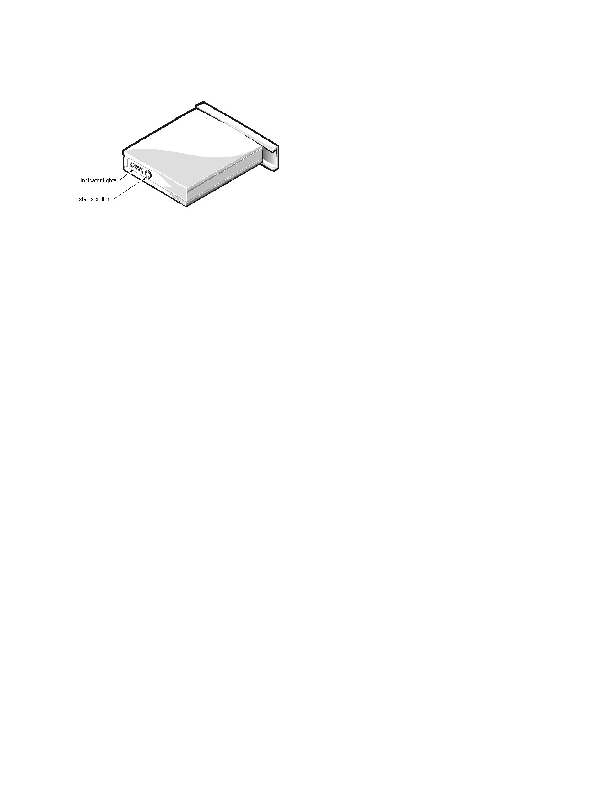
Battery Charge Gauge
Page 49

The battery charge gauge on the rear of the main and secondary batteries has 5 charge-level indicator lights that indicate how much battery charge remains. Each light
indicates approximately 20% battery charge. Press the status button to the right of the lights to check the total battery charge. If none of the lights are on, the battery
has no charge left.
Power Button
Under normal circumstances, you should only use the power button to turn on the computer or to resume from save-to-disk suspend or standby mode. To shut down
the computer, click the Start button in the Microsoft® Windows® 98 operating system, and then click Shut Down. If the computer is hung and the operating system
does not respond, press and hold the power button until the system turns off completely (this may take 4 to 8 seconds).
Display Close Button
When you close the display, this button activates Standby mode. Do not press this button.
Page 50

KeyboardRemoval:Dell™Inspiron™7000
To remove the keyboard, follow these steps:
1. Turn the computer over and remove the (4) 20-mm screws from the bottom of the computer.
2. Turn the computer back over and open the display.
3. Insert a small flat-blade screwdriver or scribe along the right top of the keyboard, just above the row of function keys. Working from right to left, free the
keyboard by prying it toward the front of the unit. When free, lift the top of the keyboard slightly to clear the palmrest assembly.
4. Slide the keyboard toward the display assembly to release the front edge of the keyboard from the palmrest assembly.
5. Rotate the bottom of the keyboard up toward the display assembly to expose the keyboard cable.
6. Disconnect the keyboard cable from ZIF connector JP14 on the system board. Use the pick to pry up the latches on each side of the connector.
7. Remove the keyboard from the palmrest assembly.
NOTICE: Lift the cable away only after the ZIF connector is opened. Pulling the cable from the connector damages the conductive
coating on the end of the cable.
Page 51

EmbeddedNumericKeypad:Dell™Inspiron™7000
Page 52

LatchAssemblyRemoval:Dell™Inspiron™7000
To remove the latch assembly, follow these steps:
1. Disconnect the LED cable from connector JP2 on the LED board.
2. Remove the 4-mm screw securing the LED board to the plastic base.
3. Remove the LED board.
4. Remove the (2) 4-mm screws holding the latch cover for the battery bay and options bay.
5. Remove the latch cover.
6. Remove the center lock over the 2 latches with springs.
7. Remove each spring and latch.
Be careful not to lose the small springs.
Page 53

LVDSBoardRemoval:Dell™Inspiron™7000
To remove the LVDS board, follow these steps:
1. Remove the 4-mm screw securing the LVDS board.
2. Gently pull the LVDS board off of connectors JP9 and JP8 on the system board. Do not rock the board to remove it, because this may damage the connectors.
Page 54

SystemBoardRemoval:Dell™Inspiron™7000
This procedure assumes that you have removed the PC Card heat sink, LVDS board, and hinge saddles. To remove the system board, follow these steps:
1. Remove the (3) 4-mm screws from the bottom of the computer.
2. Remove the system board from the bottom case.
Page 55

Memory:Dell™Inspiron™7000
Memory Installation Guidelines | Valid Memory Configurations | Removing and Installing Memory | Upper Memory Map | Conventional Memory Map
Memory Installation Guidelines
l The system can accommodate up to 384 MB of SDRAM.
l The system comes with 32 MB, 64 MB, or 128 MB of memory on the system board.
l To increase memory, install 32-MB, 64-MB, or 128-MB memory modules.
Valid Memory Configurations*
*Not all valid memory configurations are available at all times. Contact Dell for details.
Removing and Installing Memory
Base
Install
Total
32 MB
32 MB
64 MB
32 MB
32 MB + 32 MB
96 MB
32 MB
64 MB
96 MB
32 MB
32 MB + 64 MB
128 MB
32 MB
64 MB + 64 MB
160 MB
32 MB
128 MB
160 MB
32 MB
128 MB + 32 MB
192 MB
32 MB
128 MB + 64 MB
224 MB
32 MB
128 MB + 128 MB
288 MB
64 MB
32 MB
96 MB
64 MB
32 MB + 32 MB
128 MB
64 MB
64 MB
128 MB
64 MB
32 MB + 64 MB
160 MB
64 MB
64 MB + 64 MB
192 MB
64 MB
128 MB
192 MB
64 MB
128 MB + 32 MB
224 MB
64 MB
128 MB + 64 MB
256 MB
64 MB
128 MB + 128 MB
320 MB
128 MB
32 MB
160 MB
128 MB
32 MB + 32 MB
192 MB
128 MB
64 MB
192 MB
128 MB
32 MB + 64 MB
224 MB
128 MB
64 MB + 64 MB
256 MB
128 MB
128 MB
256 MB
128 MB
128 MB + 32 MB
288 MB
128 MB
128 MB + 64 MB
320 MB
128 MB
128 MB + 128 MB
384 MB
NOTICE: Ground yourself by attaching an antistatic grounding strap to your wrist and to an unpainted metal surface on the computer’s I/O panel. If
an antistatic grounding strap is not available, periodically discharge static electricity from your body by touching one of the connectors on the I/O
panel.
NOTICE: Do not install or remove a memory module when the computer is turned on or in save-to-disk suspend mode.
Page 56

1. Save any open files.
2. Shut down your computer and peripherals and unplug them from the electrical outlets.
3. Remove any installed batteries.
4. Ground yourself by touching a metal I/O connector on the back of the computer.
5. Turn the computer over, and remove the memory module cover.
Slide the memory module cover as far as it will go in the direction of the arrow and then lift it away from the computer.
6. If you are replacing one or more memory modules, remove the memory module(s).
Using your fingernails, carefully spread apart the inner metal tabs of the memory module socket just far enough for the memory module to disengage from the socket (the module
should pop up slightly). Then lift the memory module away from the socket.
7. Install the new memory module(s).
Align the notch in the edge connector with the slot in the center of the memory module socket. Press the memory module’s edge connector firmly into the socket. Pivot the module
down until it clicks.
8. Replace the memory module cover.
9. Reinstall any batteries you removed in step 3, and reconnect your computer and peripherals to electrical outlets. Turn on the peripherals and then turn on the
computer.
As the computer boots, it detects the additional memory and automatically updates the system configuration information.
10. Confirm that the system configuration information reflects the newly installed memory by checking the System Memory option on the Main Menu of the
system Setup program.
To enter the system Setup program, press <F2> while the computer is booting. The Main Menu appears. If the System Memory total is incorrect, the memory modules may not be
installed properly. Repeat steps 1 through 10 until the memory total is correct.
11. Run the RAM test group in the Dell Diagnostics to confirm that the installed memory modules are operating correctly.
For instructions on running the RAM test group in the Dell Diagnostics, see Chapter 4, "Running the Dell Diagnostics," in your Reference and Troubleshooting Guide.
12. If you added additional memory to your computer, you need to delete and recreate the save-to-disk suspend file on your hard-disk drive so that it is large
enough to accommodate the new memory. For instructions, see "Save-to-Disk Suspend File" in your online User’s Guide.
Upper Memory Map
Conventional Memory Map
NOTICE: To prevent damage to the computer, do not use tools to spread the inner metal tabs of the socket when you are installing or removing
a memory module.
NOTE: If there is 1 memory module already installed and you are adding a second memory module, the second module should be put in the
available slot. Removing existing module(s) is necessary only if they are being replaced. Depending on how you ordered your computer, there
may be 1, 2, or no modules already installed.
Location
Description
10FFF0–
Extended memory
100000–10FFEF
High memory area
0F0000–0FFFFF
System BIOS
0E0000–0EFFFF
Video BIOS
0DC000–0DFFFF
Available
0D0000–0DBFFF
PC Card memory
0C0000–0CFFFF
Available
0A0000–0BFFFF
Video RAM
09FC00–09FFFF
PS/2 mouse-data area
000000–09FBFF
Conventional memory
Segment
Address Range
Use000000h–003FFh
Interrupt vector table
00400h–004FFh
BIOS data area
00500h–005FFh
MS-DOS® work area
00600h–0FFFFh
User memory
1
10000h–1FFFFh
User memory
2
20000h–2FFFFh
User memory
3
30000h–3FFFFh
User memory
4
40000h–4FFFFh
User memory
5
50000h–5FFFFh
User memory
Page 57

6
60000h–6FFFFh
User memory
7
70000h–7FFFFh
User memory
8
80000h–8FFFFh
User memory
9
90000h–9FBFFh
User memory
9FC00h–9FFFFh
PS/2 mouse-data area
Page 58

ComboModuleDisassembly:Dell™Inspiron™7000
The combo module contains either a CD-ROM drive or a DVD-ROM drive on top of a floppy diskette drive. The combo module resides in a carrier that slides into
the options bay on the left side of the computer.
To remove the CD-ROM drive or DVD-ROM drive from the plastic carrier, follow these steps:
1. Remove the combo module.
2. Remove the (2) 3-mm screws from the L-shaped bracket.
3. Remove the bracket.
4. Remove the (2) 3-mm screws from the side of the plastic carrier.
5. Remove the (2) 3-mm screws from the bottom of the plastic carrier.
6. Disconnect the flex cable from the CD-ROM/DVD-ROM drive connector.
7. Remove the CD-ROM/DVD-ROM drive from the plastic carrier.
Turn the carrier over with one hand and let the drive fall out of the carrier into your other hand.
To remove the side mounting bracket from the CD-ROM/DVD-ROM drive, follow these steps:
1. Remove the (2) 2.5-mm screws from the side of the CD-ROM/DVD-ROM drive.
2. Remove the side mounting bracket.
To remove the diskette drive from the plastic carrier, follow these steps:
1. Remove the (2) 3-mm screws from the top of the metal shielding carrier.
2. Remove the (2) 3-mm screws from the side of the plastic carrier.
3. Lift the metal shielding carrier out of the plastic carrier.
Lift the back of the metal shielding carrier first and then slide it out.
4. Unsnap the metal latches along the top of the metal shielding carrier from the metal tabs on the bottom of the metal shielding carrier, and then remove the top.
5. Remove the diskette drive from the metal shielding carrier.
6. Remove the flex cable from the diskette drive.
7. Remove the 3-mm screw securing the mounting ear from the diskette drive, and remove the mounting ear.
When reassembling the diskette drive, be sure that the bottom of the metal shielding carrier sits inside the groove at the front of the plastic carrier.
NOTICE: The metal on the shielding carrier is sharp. Be careful not to cut yourself.
Page 59

TechNotes:Dell™Inspiron™7000
Video
I/O
Memory
Power Sources
Storage Devices
Touch Pad
Audio Devices
PC Cards
Using the Embedded Numeric Keypad
Using an External Monitor
Using an External Keyboard, Keypad, or Mouse
Power Conservation
Passwords and Security
Setup Program
Removing and Replacing Parts
Reinstalling Utilities and Drivers for Windows 98
Reinstalling Utilities and Drivers for Windows NT
Page 60

UsingtheEmbeddedNumericKeypad:Dell™Inspiron™7000
As you work, you may want to use the embedded numeric keypad to enter numbers into a spreadsheet or financial program. The embedded numeric keypad shares
some of the keys on the computer's keyboard. The embedded keypad numbers and symbols are marked on the right of the keypad keys in blue.
To activate the embedded numeric keypad, press <Num Lk>. The Number Lock indicator lights up.
To deactivate the embedded keypad, press <Num Lk>. The Number Lock indicator is no longer illuminated.
When the embedded keypad is activated, the following key combinations temporarily disable specific keypad keys:
To use the embedded arrow keys, ensure that <Num Lk> is off. Press and hold <Fn> and the corresponding key as displayed in the following list:
When Keypad Is Activated
(Number Lock Indicator ON)
Function
<Fn><key>
Enables the lowercase letter or primary function of that specific key
<Fn><Shift><key>
Enables the uppercase letter or shift function of that specific key
When Keypad Is Deactivated
(Number Lock Indicator OFF)
Function
<Fn><j>
Performs the same function as pressing <End>
<Fn><7>
Performs the same function as pressing <Home>
<Fn><k>
Performs the same function as pressing the down-arrow key
<Fn><8>
Performs the same function as pressing the up-arrow key
<Fn><u>
Performs the same function as pressing the left-arrow key
<Fn><o>
Performs the same function as pressing the right-arrow key
<Fn><.>
Performs the same function as pressing <Delete>
NOTE: The embedded numeric keypad is automatically disabled if an external keyboard or keypad is connected to the computer.
Page 61

PalmrestAssemblyandPalmrestAssemblyComponentRemoval:Dell™Inspiron™7000
MPEG-2 Card Removal | Palmrest Assembly Removal | Palmrest Assembly Component Removal
MPEG-2 Card Removal
To remove the MPEG-2 card, follow these steps:
1. Gently pull the carrier tray off of connector JP19 on the system board. Do not rock the card to remove it, because this may damage the connectors.
2. Remove the carrier tray by sliding it toward the back of the computer
3. Remove the MPEG-2 card from the carrier tray.
Palmrest Assembly Removal
This procedure assumes that you have removed the keyboard, thermal shield, and display assembly. To remove the palmrest assembly, follow these steps:
1. Turn the unit over and place it face down.
2. Remove the (2) 4-mm screws from the top inside of the combo bay.
Page 62

3. Remove the (2) 4-mm screws from the top inside of the battery bay.
4. Remove the (2) 4-mm screws from the top inside of the hard-disk drive bay.
5. Turn the unit back over.
6. Remove the (3) 6-mm screws from the top of the base assembly, along the back edge.
7. Remove the 6-mm screw from the DC-DC board.
8. Remove the 4-mm screw and the washer securing the grounding strap to the PC Card heat shield.
9. Disconnect the speaker wire harness from connector JP18 on the left side of the system board.
This wire harness also contains wiring for the touch pad and the touch pad buttons.
10. Disconnect the LED cable from connector JP10 on the system board.
11. Remove the palmrest assembly from the base assembly.
Start at the back right of the computer and move forward around the computer. Carefully lift the palmrest assembly up and pull it forward to unsnap the hidden tabs spaced around
the sides and along the top of the battery bay and options bay.
When replacing the palmrest assembly, orient the assembly in its original position on the base assembly and press firmly near each tab until the palmrest assembly snaps
into place. Start at the front to align those tabs first. Make sure that all the tabs are aligned.
Palmrest Assembly Component Removal
IR Board Removal
Hard-Disk Drive Heat Shield Removal
Touch Pad Assembly Removal
Speaker Removal
Page 63

PasswordsandSecurity:Dell™Inspiron™7000
About Passwords | Physically Securing the Computer | Disabling the Serial and Parallel Ports
About Passwords
When you receive the computer, the password features are disabled so that you can assign passwords if you wish. Once you assign a password, you must enter the
password to access the Setup program.
Use the Security menu in the Setup program to assign a password.
Physically Securing the Computer
To prevent unauthorized removal of the computer, use a security cable to attach the computer to an immovable object.
The security cable slot lets you attach a commercially available antitheft device to the computer. Antitheft devices for portable computers usually include a segment of
metal-stranded cable with an attached locking device and associated key. Complete instructions for installing this kind of antitheft device are usually included with the
device.
To prevent unauthorized removal of the computer, loop the cable around an immovable object, insert the locking device into the security cable slot, and lock the
device.
Disabling the Serial and Parallel Ports
You can disable the serial port to prevent unauthorized access to the computer through an external serial device. To disable the serial port, set the Serial Port option to
Disabled in the System Devices menu of the Setup program. In addition, you should set up a password in the Security menu of the Setup program.
You can disable the parallel port to prevent unauthorized access to the computer through an external parallel device. To disable the parallel port, set the Parallel Port
option to Disabled in the System Devices menu of the Setup program.
Disabling either port also prevents the unauthorized download of data from that port.
NOTICE: The password features provide a high level of security for the data in the computer. However, they are not foolproof. If your data requires
more security, it is your responsibility to obtain and use additional forms of protection, such as data encryption programs or PC Cards with encryption
features.
NOTE: Antitheft devices are of differing designs. Before purchasing such a device, make sure it will work with the security cable slot in the computer.
Page 64

PCCardCageRemoval:Dell™Inspiron™7000
This procedure assumes that you have removed the system board from the plastic case. To remove the PC Card cage, follow these steps:
1. Remove the 4-mm screw securing the audio bezel.
2. Remove the audio bezel.
3. Remove the (4) 18-mm screws securing the PC Card cage to the system board.
Use a support for the system board to prevent the board from flexing when the card cage screws are removed.
4. Gently pull the card cage off of connector UP9 on the system board. Do not rock the cage to remove it, because this may damage the connectors.
Replace the PC Card cage if it is damaged.
Page 65

PCCards:Dell™Inspiron™7000
PC Card Slots | Installing a PC Card | Removing a PC Card | Configuring a PC Card
PC Card Slots
The computer has 2 slots into which up to (2) 3.3- or 5-V PC Cards that adhere to the PCMCIA standard and JEIDA Release 4.2 can be installed. Both PC Card
slots support CardBUS technology. In addition, a ZV port is available from the lower slot (slot 0). If you ordered an MPEG-2 decoder PC Card from Dell, install it in
the lower PC slot for high-performance graphics.
The computer supports 2 type I, 2 type II, or 1 type III PC Card, including such memory devices as SRAM cards that emulate diskettes, RAM cards, OTP ROM
cards, and ATA cards that emulate IDE hard-disk drives. Also supported are I/O cards such as modem communication cards, LAN cards, wireless LAN cards, SCSI
cards, and sound cards. You can also use extended PC Cards in the computer.
Installing a PC Card
The PC Card slot has 2 PC Card connectors and can hold up to 2 cards in one of the following configurations:
l A single type I or type II card (using either the top or bottom PC Card connector)
l 1 type I card and 1 type II card (using either connector)
l 2 type I cards or 2 type II cards
l A single type III card (using the bottom connector)
The type of card refers to its thickness, not its functionality. Because a type III card is thicker than type I and type II cards, it takes up the entire PC Card slot,
although it uses only 1 PC Card connector.
PC Cards are generally marked (with a triangle or an arrow) to indicate which end should be inserted into the slot. The cards are keyed to prevent incorrect insertion.
If card orientation is not clear, see the documentation that came with the card.
You can install a PC Card while the computer is running. The PC Card is automatically detected. To install a PC Card, hold the card with its orientation symbol
pointing into the slot and the top side of the card facing up. Insert the card into the slot, and press in firmly until the card is completely seated in the internal PC Card
connector. If there is too much resistance when inserting the card, do not force the card. Check the card's orientation, and try again.
When a PC Card is being used, the PC Card access indicator appears in the status display panel. The computer recognizes most I/O cards and automatically loads the
appropriate device driver. If you have older modem communications software that cannot use IRQ8 or higher, you must disable the serial port or infrared port to use
the software.
Removing a PC Card
To remove a PC card from the top connector, press the top eject button twice (identified by an arrow pointing up). To remove a PC card from the bottom connector,
press the bottom eject button twice (identified by an arrow pointing down). If you are removing a type III card, press the bottom eject button twice.
The first time you press an eject button, the eject button itself pops out. The second time you press the eject button, the PC Card is released and extends slightly from
the slot. Grasp the end of the card, and pull it completely from the slot.
See Installing Utilities and Drivers for information on installing utilities and drivers.
Configuring a PC Card
If you are using the Microsoft® Windows® 98 operating system, click the Start button, point to Settings, and then click Control Panel. Double-click the PC Card to
open the PC Card Properties window. For more information, check the documentation that came with your operating system.
You can also double-click the PC Card icon on the Windows 98 desktop.
NOTE: A PC Card is not a boot device.
NOTICE: Take extra precautions if you use extended PC Cards in the computer. Extended cards are longer versions of standard PC Cards. They fit
into, and operate correctly with, the computer. However, they extend beyond the edge of the computer when installed. If something strikes the
exposed end of an installed card, the card or the system board can be damaged.
NOTICE: Because of space considerations, you may have trouble using 2 PC Cards in the computer if one of them is an extended card. Always install
an extended card in the top PC Card connector. Always remove an extended PC Card before you pack the computer for traveling.
Page 66

PCCardSlots:Dell™Inspiron™7000
Page 67

PCCardHeatSinkRemoval:Dell™Inspiron™7000
To remove the PC Card heat sink, follow these steps:
1. Remove the (2) 4-mm screws securing the PC Card heat sink.
2. Remove the heat sink.
Page 68

PowerSources:Dell™Inspiron™7000
AC Adapter | Battery | Removing and Installing the Main Battery | Removing and Installing a Secondary Battery | Charging the Battery | Checking a Battery’s Charge
Level
AC Adapter
The AC adapter kit includes the AC adapter and an AC power cable.
If you are running your computer on AC power with a battery installed, the AC adapter charges the battery (if needed) and then maintains its charge.
Battery
The computer supports up to 2 lithium ion batteries simultaneously. The main battery is a standard feature and is used in the battery compartment; an optional
secondary battery can be installed in the options bay.
Either battery can power the computer by itself. When 2 batteries are installed, the computer draws power from both of them serially. The lithium ion battery has a life
span of up to 500 full charges when it is charged at normal room temperature.
A number of factors affect battery operating time:
l The power conservation features used
l The number and type of PC Cards used
l The kinds of application programs run
l The capacity of the optional memory modules installed (the higher the capacity, the more power used)
l The use of a CD-ROM or DVD-ROM drive, which uses more power than a hard-disk drive or a diskette drive
See also Power Conservation.
Removing and Installing the Main Battery
1. Save any files you have open.
2. Shut down the computer.
3. Close the display and turn the computer over.
4. Remove the main battery.
Press the latch lock toward the back of the computer and slide the latch release away from the battery. Hold the latch release with one hand and pull the battery out of the battery
bay.
5. Install the new battery.
Make sure the bezel on the battery is in the correct position by sliding it into place. Slide the new battery into the battery compartment until you hear it click into place. Move the
latch lock back to the locked position.
6. Turn on the computer.
Removing and Installing a Secondary Battery
1. Save any open files.
2. Shut down the computer.
3. Close the display and turn the computer over.
4. Remove the combo module.
Push the latch lock toward the back of the computer, and slide the latch release away from the options bay. Hold the latch release with one hand and pull the device out of the
options bay.
5. Install a secondary battery.
Make sure the bezel on the battery is in the correct position by sliding it into place. Slide the second battery into the options bay. Move the latch lock back to the locked position.
6. Turn on the computer.
Charging the Battery
Each time you connect the computer to AC power or install a battery in a computer that is connected to AC power, the computer checks the battery's charge and
temperature. The AC adapter charges the battery (if necessary) and maintains the battery's charge.
NOTICE: The AC adapter should be in a ventilated area, such as on a desktop or on the floor, when used to power the computer or charge the battery.
Do not use the AC adapter in a poorly ventilated environment, such as inside a carrying case.
NOTICE: The AC adapter works with AC power sources worldwide. However, electrical outlets vary between countries. Before using electrical outlets
outside of the U.S., you may need to obtain a power cable designed for use in that country.
NOTICE: The AC adapter is designed to work only with Dell Inspiron portable computers. Do not use adapters from other computers, and do not
attempt to use this adapter with other computers.
Page 69

The AC adapter needs from 2 to 2.5 hours (depending on whether the system is on or off) to fully charge a battery that has been completely discharged. If 2 batteries
are installed in the computer, the AC adapter charges the main battery first, then the secondary battery. (The secondary battery is discharged first.)
For maximum battery performance, charge the battery only at normal room temperature. To charge the battery, follow these steps:
1. Connect the computer to the AC adapter.
2. Install the main battery and/or a secondary battery in the computer.
The battery starts charging immediately. The battery LED on the front of the computer appears as a solid green light while the battery is charging. If you remove a battery from the
computer while the battery is charging, the indicator lights on the battery will stay lit for a few minutes.
Checking a Battery's Charge Level
Use one of the following methods to check the battery's charge level:
l Check the battery charge gauge before you insert the battery into your computer. When the battery is in the computer, you cannot see the gauge. The gauge has
5 charge-level indicator lights that show how much battery charge remains. Press the status button to the right of the lights to check the charge level. Each light
represents approximately 20% of the total battery charge. For example, if the battery has 80% of its charge remaining, 4 of the lights are on. If none of the lights
are on, the battery has no charge left.
l A low-battery warning occurs when the battery is about 90% depleted. The speaker beeps 3 times, and the battery status LED is a solid amber. About 12
minutes of battery life remains. If both the main battery and the secondary battery are installed, the low-battery warning means that the combined charge of both
batteries is about 90 percent depleted.
l If you are using the Microsoft
®
Windows® 98 operating system, click the Start button, point to Settings, and then click Control Panel. Double-click the
Power icon to open the Power Properties window. (Alternatively, right-click the battery icon in the taskbar of the Windows 98 desktop. From there you can
open the Power Properties window or the battery meter.) The Windows 98 battery meter displays a battery icon that shows the amount of battery charge
remaining. If an AC adapter is connected to the computer, the battery meter displays a plug icon. The battery meter icons are visible in the desktop taskbar. For
more information, see your Windows 98 documentation.
NOTE: You can leave the battery in the computer as long as you like. The battery's built-in circuitry prevents the battery from overcharging.
NOTICE: If only 1 or none of the charge-level indicator lights are lit, it indicates a critically low battery state. Do not use the battery
unless the computer is connected to AC power or unless you install a second charged battery.
NOTICE: To avoid losing data (and possibly corrupting data areas on your hard-disk drive), save your work immediately after a lowbattery warning. Then connect the computer to AC power, or install a secondary battery in the options bay. If the battery runs completely
out of power, the computer activates save-to-disk suspend mode.
Page 70

PowerConservation:Dell™Inspiron™7000
How to Conserve Battery Power | Using Microsoft Windows 98 to Conserve Battery Power | Experimenting with Power Conservation | Checking the Battery Status |
Standby Mode | Turn Off Monitor | Turn Off Hard-Disk Drive | Save-to-Disk Suspend Mode | Save-to-Disk Suspend File
How to Conserve Battery Power
You automatically conserve battery power each time you attach an AC power source to the computer. When the AC adapter is attached, the battery is being charged
while the computer uses AC power. The life expectancy of your battery is determined largely by the number of charges it receives, so use an AC power source to run
the computer if one is available.
Use the Microsoft Windows 98 Power Management Properties window to adjust the way the computer uses battery power. Options in the window slow or stop
some internal devices when the computer is idle.
Take advantage of the computer's power management modes when you leave the computer unattended for long periods of time. Standby, Turn Off Monitor, and
Turn Off Hard Drive allow you to maximize power conservation when your work is interrupted.
When the computer is using battery power, remove PC Cards that you are not using.
Experiment with power conservation features to achieve the optimum power conservation for your work environment.
Using Microsoft® Windows® 98 to Conserve Battery Power
Complete the following steps in Windows 98 to access the Power Management Properties window and set the power management features:
1. Click the Start button, point to Settings, and click Control Panel.
2. Double-click the Power Management Properties icon.
The Power Management Properties window contains the following tabs:
l Power Scheme allows you to select one of 3 power mode settings.
l Alarms allows you to set the Low battery and Critical battery alarms to alert you when the system battery falls below a certain percentage. When you received your
computer, the Low battery and Critical battery alarms check boxes were not checked. Dell recommends that you do not select these options.
l Power Meter allows you to view the percentage of battery life remaining when your system is operating on battery power. If your system is operating on AC power,
the system displays a message.
l Advanced allows you to display the Power Meter on the Windows 98 taskbar and to display a password prompt when the computer resumes from Standby mode.
3. Select the appropriate settings for the power management features you want.
Experimenting with Power Conservation
In general, the lower the value you set for each time-out option, the longer your battery's charge lasts. On the other hand, setting high time-out values tends to optimize
the computer's performance. For best results, experiment as follows:
l Use the computer with all the options set to their defaults.
l Use the computer with all the time-out options disabled or set to Off.
l Use the computer with all the time-out options set to their minimum values.
Evaluate the way that the different time-out settings affect how long you can operate the computer on battery power versus the relative efficiency of how your software
performs.
Checking the Battery Status
The battery LED on the front of the computer indicates the battery's current operating status. The LED has 5 states:
l Off when the computer is operating on battery power.
l Flashing green, which indicates that the battery is charging.
l Solid green, which indicates that the battery is fully charged.
l Solid amber, which indicates that the power is low; you should save your work and attach AC power.
l Fast blinking amber, which indicates that the battery power is critically low. Save your work and attach AC power immediately.
Standby Mode
NOTE: You might have to trade some of the computer's performance for increased battery operating time. For example, if you activate the Turn Off
Hard Drive mode, you may experience a delay the next time the computer tries to access the drive.
Page 71

Standby turns off the display, stops the hard-disk drive, and turns off other internal devices so that the computer uses less battery power. When the computer resumes
operation from Standby mode, the desktop is restored exactly as it was before entering Standby mode.
You can activate Standby mode by pressing <Fn><Esc> or by selecting Standby in the Shutdown window. To resume operation from Standby mode, press the
power button.
Turn Off Monitor
The Turn Off Monitor option turns off the display so that the computer uses less battery power. You can press any key or the touch pad to turn on the display. The
desktop is restored exactly as it appeared before the display was turned off.
Turn Off Hard-Disk Drive
The Turn Off Hard-Disk Drive option turns off the hard-disk drive so that the computer uses less battery power. You can press any key or the touch pad to turn on
the hard-disk drive. The desktop is restored exactly as it appeared before the hard-disk was turned off.
Save-to-Disk Suspend Mode
Save-to-disk suspend mode copies all system data to a reserved area on the hard-disk drive and then turns off all power to the computer. When you resume normal
operation, the same programs will be running and the same files will be open that were open before you activated this mode.
To activate save-to-disk suspend mode immediately, press <Fn> <A> (or <Fn> <Q> on the French keyboard).
To resume using the computer after activating save-to-disk suspend mode, press the power button. It may take a few seconds for the computer to return to its previous
state.
Some PC Cards may not operate correctly after exiting from save-to-disk suspend mode. If you encounter problems with a card, remove and replace it.
Save-to-Disk Suspend File
The save-to-disk suspend file on your hard-disk drive cannot be accessed by the operating system or application programs. When save-to-disk suspend mode is
activated, all system data is stored in this file.
Use the following instructions to create a save-to-disk suspend file if you installed a new hard-disk drive, if you removed the file, or if you are rebuilding a corrupted
hard-disk drive. If possible, print these instructions before you begin this procedure.
1. Save and exit any application programs and files that you have open and shut down the computer.
2. Insert the Microsoft Boot Disk Windows 98 Series diskette into the diskette drive.
3. When the Microsoft Windows 98 Startup Menu appears, use the down-arrow key to select Start computer with CD-ROM support and press <Enter>.
4. When A:\> appears on the screen, insert the Dell Inspiron 7000 System Software CD into your CD-ROM or DVD-ROM drive.
Your MS-DOS prompt changes from an A:\ to a D:\, assuming that D is the drive letter of your CD-ROM or DVD-ROM drive.
5. Type cd\utilities and press <Enter>.
6. Type phdisk /create /file and press <Enter>.
The utility calculates the size of the file, in kilobytes, based on the amount of system memory in your computer, plus 2 MB to handle video memory and additional system
requirements.
NOTICE: Windows 98 saves data to RAM, not to your hard-disk drive, before entering Standby mode. If the computer enters Standby mode while
running on battery power, data loss from RAM can occur if the battery discharges completely.
NOTES: Save-to-disk suspend mode helps preserve system data by quickly saving it on to the hard-disk drive if you are about to run out of battery
power.
Place the computer in save-to-disk suspend mode if you do not intend to store the computer for longer than 40 days. Save-to-disk suspend mode
preserves the configuration information stored in NVRAM. The reserve battery maintains this information, but may run out of energy after 40 days.
NOTE: Save-to-disk suspend mode requires a special file on your hard-disk drive that sets aside enough disk space to store the contents of the
computer's memory. Dell creates an appropriately sized save-to-disk suspend file before shipping the computer to you. If you remove the file or add
memory to the computer, or if your hard-disk drive becomes corrupted, you must recreate the file before you can again use save-to-disk suspend mode.
NOTE: If you installed memory to increase system memory, delete the save-to-disk suspend file and then complete this procedure. To delete the saveto-disk suspend file, type the following at the MS-DOS prompt and press <Enter>:
phdisk /delete /file
NOTE: Make sure that there is a space between phdisk /create and /file.
Page 72

7. Follow the instructions on your screen to create the save-to-disk suspend file.
To check the size of the save-to-disk suspend file, type phdisk /info at an MS-DOS prompt and press <Enter>.
If you need to delete the save-to-disk suspend file, type phdisk /delete /file at an MS-DOS prompt and press <Enter>.
Page 73
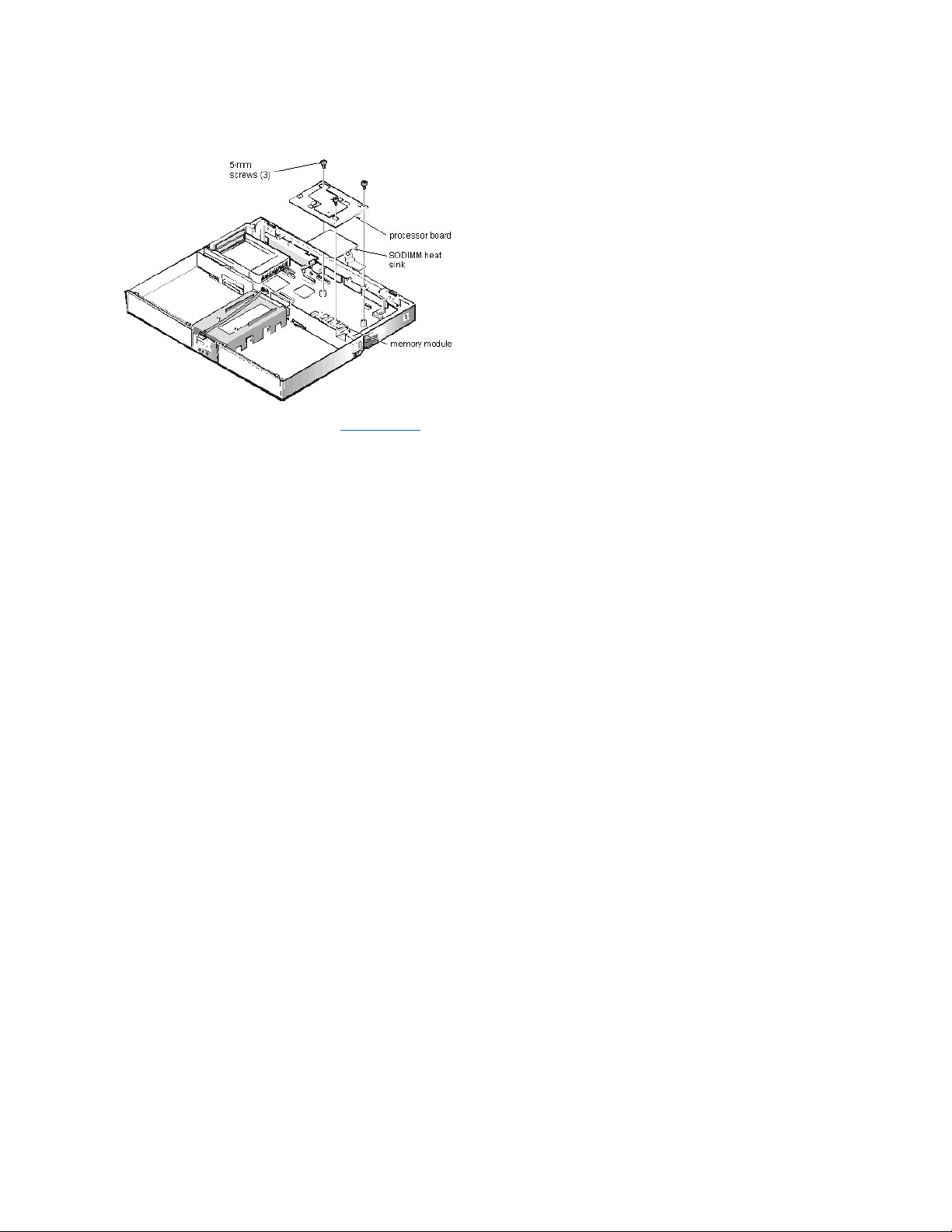
ProcessorBoardandMemoryModuleRemoval:Dell™Inspiron™7000
This procedure assumes that you have removed the heat exchanger/fan. To remove the processor board and memory module, follow these steps:
1. Remove the (3) 5-mm screws securing the processor board to the system board.
2. Gently pull the processor board off of connector JP15 on the system board. Do not rock the board to remove it, because this may damage the connectors.
3. Lift the SODIMM heat sink off of the memory module.
4. Remove the memory module.
Carefully spread the inner metal tabs of the memory module socket to disengage the module from the socket. The module should pop up slightly. Then pull the memory module out of
the socket.
5. Inspect the thermal pad beneath the memory module to see if it needs replacement.
When reinstalling the SODIMM heat sink, be careful to align the hole in the SODIMM heat sink over the metal clip soldered to the system board.
When reinstalling the processor board, align the board with the notch on the system board connector. Press down on the left side of the board over the system board
connector. This is the best spot to apply pressure to seat the processor correctly on connector JP15.
Page 74

RemovingtheMemoryModule:Dell™Inspiron™7000
Page 75
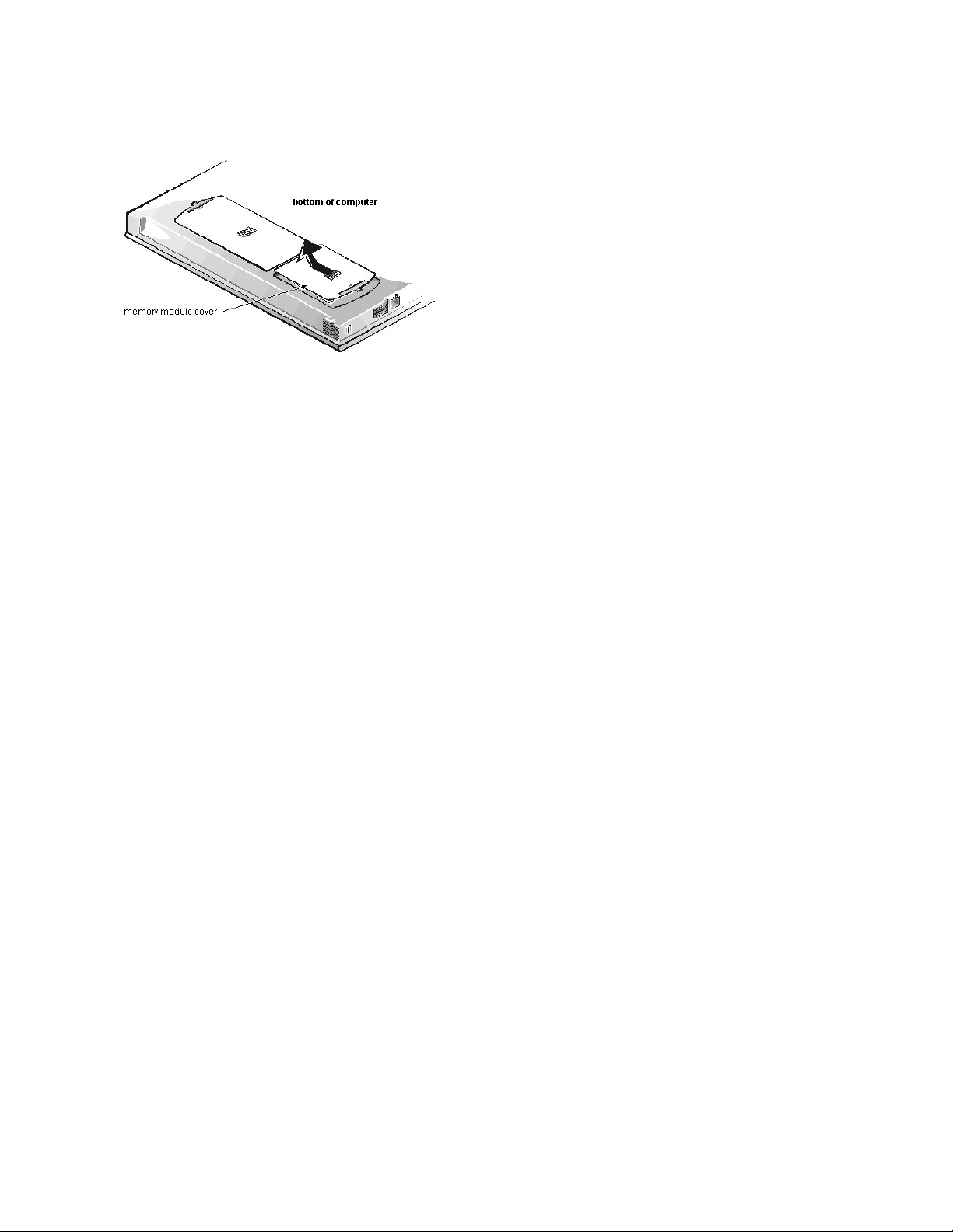
RemovingtheMemoryModuleCover:Dell™Inspiron™7000
Page 76

RemovingandReplacingParts:Dell™Inspiron™7000
Precautionary Measures | Service Procedures | Recommended Tools
Precautionary Measures
Precautionary measures include disconnecting the computer from the AC adapter and port replicator and removing the main battery, PC Cards, hard-disk drive,
memory module cover, memory modules, and devices in the options bay.
To take these precautionary measures, follow these steps:
1. Determine the power state of the computer.
If the system is on, go to step 2. If you are unsure whether the system is on, shut down and restart the system, and then go to step 2.
2. Turn off any attached peripherals, and then shut down the computer.
3. Disconnect the computer and any attached peripherals from electrical outlets to reduce the potential for personal injury or shock.
If the computer has an AC adapter, disconnect the AC power cable from the electrical outlet and then from the AC adapter; then disconnect the AC adapter from the computer or
from the Inspiron Port Replicator II.
4. If the computer is connected to a port replicator, pull both release handles on the sides of the replicator to undock the computer.
5. Remove the main battery from the battery compartment.
Unlock the latch lock on the bottom of the computer by flipping it toward the back of the computer. Slide the latch release in the direction of the arrow. Keep holding the latch release
with one hand while pulling the battery out of the compartment with the other.
WARNING FOR YOUR PERSONAL SAFETY AND PROTECTION OF THE EQUIPMENT
Before you start to work on the computer, perform the following steps in the sequence indicated:
1. Ground yourself by attaching an antistatic grounding strap to your wrist and to an unpainted metal surface on the computer’s I/O panel. If an
antistatic grounding strap is not available, periodically discharge static electricity from your body by touching one of the connectors on the I/O
panel.
2. Turn off the computer and any attached peripherals.
3. Disconnect the computer and any attached peripherals from electrical outlets to reduce the potential for personal injury or shock.
Page 77

6. Remove PC Cards.
To remove PC Cards from the top connector, press the top eject button. When the button slides out, press it again to release the card. Gently remove the card. Press the eject button
again until it is flush with the computer casing. To remove PC Cards from the bottom connector, follow the same procedure.
Grasp the end of the card, and pull it completely from the slot.
7. Remove the hard-disk drive assembly.
Loosen the 2 captive screws that secure the hard-disk drive into the bottom of the computer. The front edge of the cover pops up slightly. Slide the hard-disk drive toward the front
of the computer and then lift the drive out of the computer.
8. Remove the memory module covers.
Slide the memory module cover as far as it will go in the direction of the arrow, and then remove the cover.
NOTICE: Use the PC Card configuration utility on the taskbar to select and stop a card before removing it from the computer. If you do
not remove the card in configuration utility, you could lose data from open application programs.
NOTICE: When the hard-disk drive is not in the computer, store it in a hard-disk drive case to protect it from exposure to static
electricity.
NOTICE: Handle the hard-disk drive gently and don’t bump or drop the drive. Rough handling of the drive could induce failure or loss of
data.
Page 78

To replace a cover, place it over the opening, leaving a small gap along the rounded edge, and then slide the cover toward the outside of the computer until it snaps into
place.
9. Remove the memory modules.
Carefully spread apart the inner metal tabs of the memory module socket to disengage the module from the socket. The module should pop up slightly. Then pull the memory module
out of the socket.
10. If present, remove the combo module or secondary battery from the options bay.
Unlock the latch lock by flipping it toward the back of the computer. Slide the latch release in the direction of the arrow. Keep holding the latch release with one hand while pulling
the combo module or secondary battery straight out of the options bay with the other.
Service Procedures
Unless otherwise noted, each procedure assumes the following:
l You have the recommended tools.
l You have performed the steps in Precautionary Measures.
l The computer and any attached peripherals are turned off and the peripherals are disconnected from the computer's I/O panel.
l You can replace or reinstall a part by performing the removal procedure in reverse order unless additional information is provided.
Screw Identification and Tightening
NOTE: If the computer is booted with a diskette drive or secondary battery in the options bay, you must reboot after installing the combo module in
the options bay.
NOTICE: Only a certified service technician should perform the following procedures for removing and replacing parts. The warranty on the
computer becomes void if anyone other than a certified technician performs these procedures.
Page 79

ZIF Connectors
Exploded View of Computer
Exploded View of 13.3-Inch Display Assembly
Exploded View of 14.1-Inch Display Assembly
Exploded View of 15-Inch Display Assembly
Exploded View of Palmrest Assembly
Exploded View of Base Assembly
Hard-Disk Drive Disassembly
Combo Module Disassembly
General Disassembly
Keyboard Removal
Thermal Shield and Internal Modem Removal
Display Assembly and Display Assembly Component Removal
Palmrest Assembly and Palmrest Assembly Component Removal
Base Assembly Component Removal
Recommended Tools
Most of the procedures require the use of one or more of the following tools:
l Small flat-blade screwdriver
l Number 1 Phillips-head screwdriver
l Antistatic grounding strap
l Dental pick
l Small scribe or nylon flat blade
l Nut drivers (5 mm and 5.5 mm)
Page 80

Removing the Hard-DiskDrive:Dell™Inspiron™7000
Page 81

RJ-11CardRemoval:Dell™Inspiron™7000
To remove the RJ-11 card, follow these steps:
1. Remove the 4-mm screw securing the RJ-11 card to the system board.
2. Lift the card off the system board.
Page 82

RemovingDevicesFromtheMediaBay:Dell™Inspiron™7000
Page 83

ScrewIdentificationandTightening:Dell™Inspiron™7000
Where applicable, information about screw lengths is provided in illustrations. A complete screw inventory and location template is included in General Disassembly.
NOTICE: The correct-length screw must be used when reinstalling a screw. Otherwise, hardware damage could result. Make sure that the screw is
properly aligned with its corresponding hole, and avoid overtightening.
Page 84

SecurityCableSlot:Dell™Inspiron™7000
Page 85

SetupProgram:Dell™Inspiron™7000
Using the Setup Program | Main Menu | System Devices Menu | Security Menu | Power Menu | Boot Menu | Exit Menu
Using the Setup Program
For detailed information about the Setup menus and options, see the online User's Guide.
You can enter the Setup program only when the computer is booting. Each time you turn on or boot the computer, the following message appears:
Press <F2> to enter Setup
To open the Main menu of the Setup program, press <F2> before the message disappears.
From the Main menu, you can access the System Devices menu, the Security menu, the Power menu, the Boot menu, and the Exit menu.
Change option settings in the menus to customize the configuration of the computer. The legend at the bottom of each menu tells you which keys to use for navigating
through the Setup program.
Main Menu
System Devices Menu
NOTE: Press <F9> to restore the default values for each option in a menu. To save changes and exit from the Setup program, press <F10>. Press
<F5> or <F6> to change the value for an option.
Page 86

Security Menu
Power Menu
Boot Menu
Exit Menu
NOTICE: The password features provide a high level of security for the data in the computer. However, they are not foolproof. If your data requires
more security, it is your responsibility to obtain and use additional forms of protection, such as data encryption programs or PC Cards with encryption
features.
Page 87

Page 88

SpeakerRemoval:Dell™Inspiron™7000
This procedure assumes that you have removed the palmrest assembly from the base assembly and that you have removed the hard-disk drive heat shield and touch
pad assembly. To remove the speakers, follow these steps:
1. Remove any tape securing the speaker cables.
2. Remove the (3) 4-mm screws securing the left speaker cover.
3. Remove the left speaker cover, speaker, and speaker cable.
4. Remove the speaker wire harness.
5. Remove the (2) 4-mm screws securing the right speaker cover.
6. Remove the right speaker cover, speaker, and speaker cable.
The display latch is no longer secured by the speaker covers. Be careful not to lose the spring.
7. Remove the display latch and spring.
To replace the speaker, resolder the speaker cable to the new speaker.
When reinstalling the speakers, be especially careful to route the speaker cables and speaker wire harness through the appropriate slots and pins.
NOTE: Before removing the speaker cables and wire harness, be sure to note their routing through the slots and pins so you can correctly
reinstall the components.
Page 89

Specifications:Dell™Inspiron™7000
Microprocessor | Chip Set and Bus | PC Card | Memory | Connectors | Audio | Video | 14.1-Inch Display | 15-Inch Display| Keyboard | Touch Pad | Battery | AC
Adapter | Environmental | Regulatory
Microprocessor
Chip Set and Bus
PC Card
Memory
Microprocessor type and speed:
Dell Inspiron 7000A
Intel® Mobile Pentium® II microprocessor running at
400, 366, or 333 MHz
Dell Inspiron 7000D
Intel Mobile Pentium II microprocessor running at 300
or 266 MHz
Dell Inspiron 7000C
IntelCeleron™microprocessorrunningat400or366
MHz
L1 cache:
Dell Inspiron 7000A
32 KB (internal)
Dell Inspiron 7000D
32 KB (internal)
Dell Inspiron 7000C
32 KB (internal)
L2 cache:
Dell Inspiron 7000A
256 KB (integrated)
Dell Inspiron 7000D
512 KB pipe-lined-burst SRAM (external)
Dell Inspiron 7000C
128 KB (integrated)
Math coprocessor
internal to the microprocessor
System chip set
Intel Mobile 440BX AGP
Data bus width
64 bits
DRAM bus width
64 bits
Address bus width
32 bits
Flash EPROM
4 Mb
PCI controller
Texas Instruments PCI 1220 CardBus controller
PC Card connectors
2 type I, 2 type II cards, or 1 type III card
Cards supported
3.3 and 5 V
PC Card connector size
68 pins
Data width (maximum)
32 bits
Architecture
SDRAM
Memory module capacities
32-, 64-, and 128-MB SODIMM
Maximum RAM
384 MB
Memory access time/clock frequency
66 MHz
BIOS address
F000:0000
Page 90

Connectors
Audio
Video
14.1-Inch Display
Serial (DTE)
(1) 9-pin connector; 16550-compatible, 16-byte buffer
Parallel
(1) 25-hole connector; normal (unidirectional), bidirectional, EPP 1.9 or
ECP
Monitor
(1) 15-hole connector
PS/2 keyboard/mouse
(1) 6-pin mini-DIN connector
Infrared
1 IrDA 1.1 port
Expansion connector
240 pins
TV-out
(1) 7-pin S-video
Audio
microphone, headphones/speakers, and line-out jacks
USB
(1) 4-pin connector
RJ11
1 RJ11 modem port (optional)
Audio type
Sound Blaster Pro-compatible voice and music functions, HRTF 3D
positional audio, hardware wavetable
Audio controller
ESS Technology Maestro-2
Conversion
20 bit (stereo analog-to-digital and digital-to-analog)
Hardware wavetable synthesizer
64-voice
Interfaces:
Internal
PCI bus, integrated stereo speakers and microphone
External
microphone (minijack, mono), headphones, line-in
Internal speaker amplifier
1.0-W stereo (0.5 W per speaker)
External microphone input voltage range
280 mV peak-to-peak
Line/audio input voltage range
2.8 V peak-to-peak
Controls
volume can be controlled through thumb wheel, software application
menus, and keyboard
Video type
AGP 2X with sideband signals, hardware 3D accelerator, DVD motion
compensation, ImpacTV2-quality TV output
Video controller
ATI RAGE Mobility - P video with AGP 2x, 4M/8M SGRAM
Video memory
4- or 8-MB 100-MHz SGRAM
LCD interface
65-MHz LVDS
TV support
NTSC or PAL in S-video and composite modes
Type
active-matrix color (XGA)
Dimensions (active area):
Height
54 mm (2.1 inches)
Width
318 mm (12.5 inches)
Depth
254 mm (10 inches)
Diagonal
358.1 mm (14.1 inches)
Page 91

15-Inch Display
Keyboard
Touch Pad
Battery
Weight*
3.8 kg (8.37 lb)
Maximum resolution
1024 x 768 pixels; 4 billion colors as supported by application software
Response time (typical)
40 ms
Operating angle
0°(closed)to170°
Dot pitch
0.28 mm
Power consumption
4.6 W
Controls
brightness can be controlled through key combinations
* Includes hard-disk drive, diskette drive, and CD-ROM drive.
Type
active-matrix color (XGA)
Dimensions (viewable image area):
Height
59 mm (2.3 inches)
Width
328 mm (12.9 inches)
Depth
263 mm (10.4)
Weight*
4.1 kg (8.9 lb)
* Includes hard-disk drive, diskette drive, and CD-ROM drive.
Number of keys
87 (U.S. and Canada); 88 (Europe); 88 (Japan)
Key travel
3.0 ± 0.5 mm (0.12 ± 0.02 inch)
Key spacing
19.1 mm (0.75 inch)
Layout
QWERTY/AZERTY/Kanji
Interface
PS/2-compatible
X/Y position resolution (graphics table mode)
20 points/mm (500 points/inch)
Size:
Thickness
4.65 mm (0.18 inch) at highest component
Width
64-mm (2.52-inch) sensor-active area
Height
47.0-mm (1.85-inch) rectangle with 0.5-mm (0.02-inch) tabs
Weight*
15 g (0.52 ounce) ± 0.5 g (0.001 ounce)
Power:
Supply voltage
5 V ± 10%
Supply current
4 mA (maximum operating current)
Type
lithium ion
Dimensions:
Height
23.8 mm (0.94 inch)
Page 92

AC Adapter
Environmental
Depth
148.2 mm (5.83 inches)
Width
116.2 mm (4.58 inches)
Weight*
0.66 kg (1.45 lb)
Voltage
14.8 VDC
Capacity
74 WH
Charge time (approximate)*
3.75 hours (computer on); 3.25 hours (computer off)
Operating time (approximate)*
2.75 to 3.75 hours with 1 battery;
5.5 to 7.5 hours with 2 batteries
Life span (approximate)*
500 discharge/charge cycles
Ambient temperature range:
Charge
0°to45°C(32°to113°F)
Discharge
0°to60°C(32°to140°F)
Storage
-20°to60°C(-4°to140°F)
* Battery performance features such as charge time, operating time, and life span can vary according to the conditions
under which the computer and battery are used.
Input voltage
90 to 264 VAC
Input current (maximum)
1.5 A at 90 VAC, full load
Input frequency
47 to 63 Hz
Output current
3.5 A (continuous)
Output power
70 W
Rated output voltage
20 VDC
Dimensions:
Height
29.6 mm (1.17 inches)
Width
60.0 mm (2.36 inches)
Depth
105 mm (4.13 inches)
Weight (with cables)
0.3 kg (0.66 lb)
Temperature range:
Operating
5°to35°C(41°to95°F)
Storage
-20°to50°C(-4°to122°F)
Temperature:
Operating
5°to35°C(41°to95°F)
Storage
-20°to50°C(-4°to122°F)
Relative humidity
10% to 90% (noncondensing)
Maximum vibration:
Operating
0.8 GRMS using a random-vibration spectrum that simulates air/truck
shipment
Storage
1.3 GRMS using a random-vibration spectrum that simulates air/truck
Page 93

Regulatory
shipment
Maximum shock:*
Operating
1.52 m/sec (4.98 ft/sec) (less than or equal to a pulse width of 2 ms)
Storage
2.03 m/sec (6.66 ft/sec) (less than or equal to a pulse width of 2 ms)
Altitude:
Operating
0 to 3048 m (0 to 10,000 ft)
Storage
0 to 12,192 m (0 to 40,000 ft)
* Measured with the hard-disk drive in head-parked position
U.S.
FCC Class B
Canada
IC Notice
Europe
CE NOTICE: EN 55022, EN 50082-1, IEC 801-2, IEC 801-3, IEC
801-4, EN 60950:1992 + Amd.1:1993 + Amd.2:1993
Czech Republic
EN 55022 Compliance
Japan
VCCI Class A or Class B ITE
Korea
Class A or Class B
Poland
PN-93/T-42107 and PN-89/E-06251
Mexico
NOM 024
Taiwan
BSMI notice
Page 94

StatusDisplay:Dell™Inspiron™7000
on top of computer, above keyboard:
on front of computer, beneath display latch:
Page 95

StatusDisplay:Dell™Inspiron™7000
These status lights are above the keyboard:
These status lights are on the front of the computer, beneath the display latch:
Page 96

StorageDevices:Dell™Inspiron™7000
Removing and Installing a Device in the Media Bay
Installing and Removing Devices Using Softex BayManager | Hard-Disk Drive
Removing and Installing a Device in the Media Bay
The media bay holds a second battery, a combination CD-ROM drive/diskette drive, or a combination DVD-ROM drive/diskette drive.
To remove a device from the media bay, perform the following steps:
1. Save any open files.
2. Shut down the computer.
3. Remove the currently installed device from the media bay.
Close the display and turn the computer over. Push the latch lock to the unlocked position, and slide the latch release in the direction of the arrow. Keep holding the latch release
with one hand while pulling the device out of the media bay with the other.
4. Install the new device in the media bay.
Insert the device into the media bay and push the latch lock back into the locked position. The label on the device will be facing away from you when the computer is turned over.
5. Reboot the system.
Installing and Removing Devices Using Softex BayManager
To install or remove a device from the media bay using Softex BayManager, perform the following steps.
1. Double-click the Softex BayManager icon, , on the taskbar.
2. Click either Remove/Swap Bay Device(s) or Insert Bay Device(s) and follow the instructions on the screen.
Hard-Disk Drive
Use the following procedure to install a hard-disk drive.
1. Save any open files.
2. Shut down the computer and remove any installed batteries.
3. Remove the currently installed drive.
Turn the computer over, and loosen the two screws securing the hard-disk drive cover. The screws are held captive in the lip of the carrier. A spring causes the front edge of the
cover to pop up. If the front edge of the cover does not pop up, pull on one of the screws to lift the front edge.
4. Push the hard-disk drive forward until it stops, and then pull it up.
5. Remove the new drive from its packaging.
Save the original packaging to use when storing or shipping the hard-disk drive.
NOTE: If you are using Softex BayManager, refer to Installing and Removing Devices Using Softex BayManager and skip the following procedure.
NOTE: All devices are removed and installed the same way.
NOTE: If you boot the system with a device in the media bay, you must reboot after installing another type of device in the media bay.
NOTE: f you do not have Softex BayManager, the icon does not appear in the Control Panel or on the taskbar. If you do not have Softex
BayManager, see Removing and Installing a Device in the Media Bay.
NOTES: You will need the Microsoft®Windows®98 CD and the Dell Inspiron 7000 System Software CD to install software on the new hard-disk drive.
The computer's BIOS may not support hard-disk drives obtained from vendors other than Dell. Dell does not guarantee compatibility or provide
support for hard-disk drives obtained from other sources.
NOTICE: To prevent data loss, shut down your computer before removing or installing your hard-disk drive. Do not remove the hard-disk drive if the
computer is in suspend mode or save-to-disk mode or if the hard-disk drive access indicator is lit.
NOTICE: When the hard-disk drive is not in the computer, protect the drive from exposure to static electricity by storing it in protective
packaging.
NOTICE: While sliding the drive in, do not force it into place.
Page 97

6. Slide the new drive into place.
There may be some resistance as the drive connects to its interface connector at the back of the bay.
7. Tighten the screws you loosened in step 3.
8. Test the drive by running the Hard-Disk Drives (Non-SCSI) test group in the Dell Diagnostics.
For information on running the diagnostics, see Chapter 4, "Running the Dell Diagnostics," in the Dell Inspiron 7000 Reference and Troubleshooting Guide.
Page 98

TouchPadAssemblyRemoval:Dell™Inspiron™7000
This procedure assumes that you have removed the palmrest assembly from the base assembly and that you have removed the hard-disk drive heat shield. To remove
the touch pad assembly, follow these steps:
1. Remove the (3) 4-mm screws securing the touch pad button board.
2. Disconnect the 2 speaker cables from connectors JP5 and JP3 on the touch pad button board.
3. Disconnect the speaker wire harness from connector JP1 on the touch pad button board.
4. Disconnect the touch pad flex cable from ZIF connector JP4 on the touch pad button board. Use the pick to pry up the latches on each side of the connector.
5. Disconnect the touch pad flex cable from ZIF connector J1 on the touch pad. Use the pick to pry up the brown center piece on the connector.
6. Remove the touch pad button board.
7. Remove the (4) 4-mm screws securing the touch pad bracket.
8. Remove the touch pad bracket.
9. Remove the touch pad.
The touch pad buttons are heat-staked into the palmrest assembly and are not removable.
NOTICE: Lift away the cable only after the ZIF connector is opened. Pulling the cable from the connector damages the conductive coating
on the end of the cable.
NOTICE: Lift away the cable only after the ZIF connector is opened. Pulling the cable from the connector damages the conductive coating
on the end of the cable.
Page 99

TouchPad:Dell™Inspiron™7000
Page 100

TouchPad:Dell™Inspiron™7000
Using the Touch Pad | Installing the Touch Pad/Mouse Driver
Using the Touch Pad
The PS/2-compatible touch pad detects the position of your finger over a touch-sensitive area and provides the computer full mouse functionality. The touch pad's 2
buttons correspond to the left and right buttons on a standard mouse.
To move the cursor, lightly slide your finger over the smooth sensor area. To select an object, gently tap once on the surface of the touch pad. To select and move (or
drag) an object, position the cursor on the object and tap down-up-down on the touch pad. On the second down motion, leave your finger on the touch pad and move
the selected object by sliding your finger across the surface. To double-click an object, position the cursor on the object and then tap twice.
To customize touch pad and cursor features, follow these steps:
1. Click the Start button, point to Settings, and then click Control Panel.
The Control Panel window appears.
2. Double-click the Mouse icon.
3. Select the Touch Pad tab.
4. Make your selections. Click the Help button if you need more information.
To use the touch pad, the PS/2 Mouse option in the System Devices menu of the Setup program must be set to Enabled. Dell has already installed the touch pad
drivers for you.
Installing the Touch Pad/Mouse Driver
See Reinstalling Utilities and Drivers for information about reinstalling touch pad/mouse drivers.
NOTE: Keep your fingers away from the touch pad while the computer is booting or loading the operating system. If you touch the touch pad at either
time, the cursor will not move until you remove your finger from the touch pad surface.
 Loading...