

Page 1
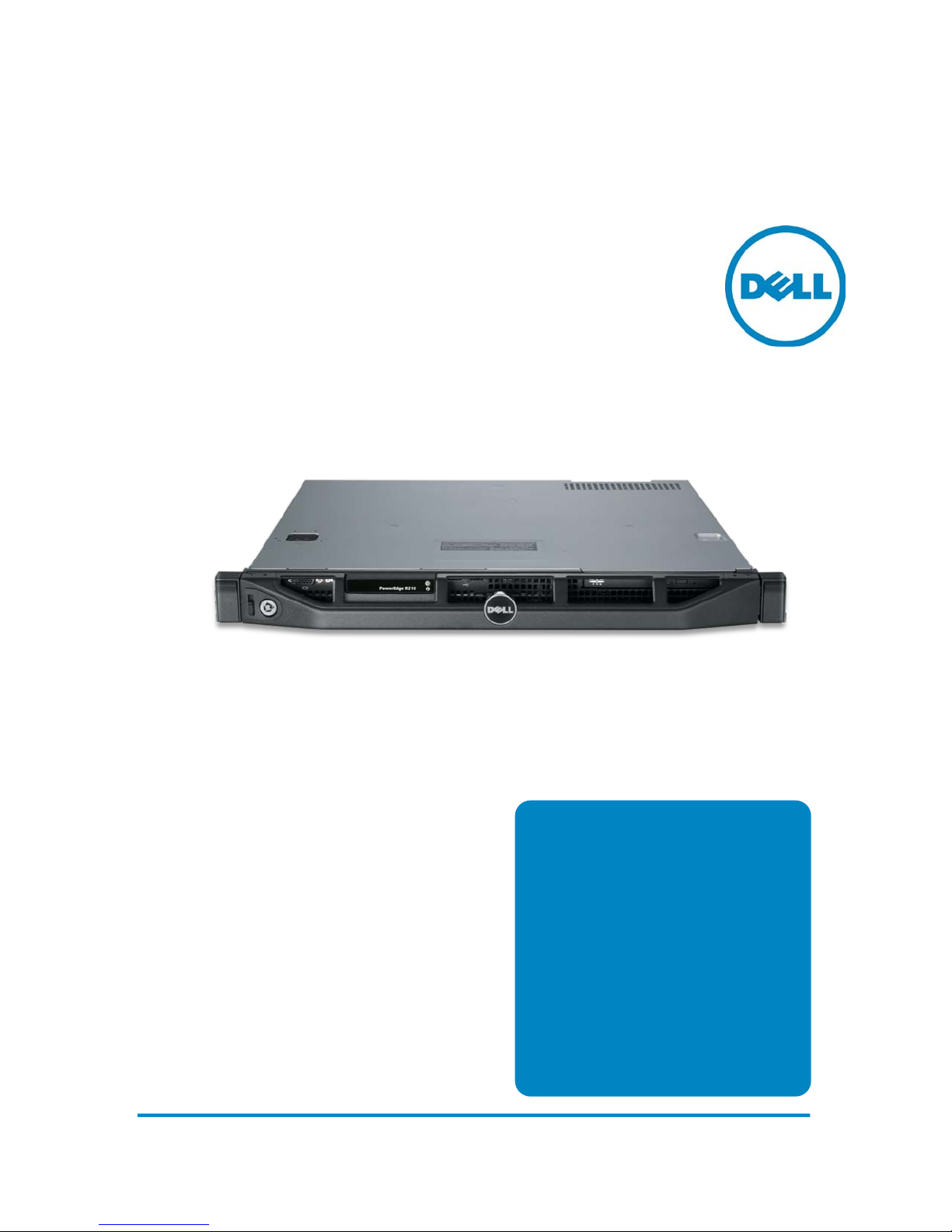
Technical Guide
1-socket 1U rack
Dell PowerEdge R210
server providing
the features you
need without a
lot of the
unnecessary
extras.
Page 2

Dell
This document is for informational purposes only. Dell reserves the right to make
changes without further notice to any products herein. The content provided is as is
and without express or implied warranties of any kind.
Dell, PowerEdge, PowerVault, OpenManage , and ReadyRails are trademarks of Dell,
Inc. Citrix
®
and XenServer™ are trademarks of Citrix Systems, Inc. and/or one or more
of its subsidiaries, and may be registered in the United States Patent and Trademark
Office and in other countries. ENERGY STAR is a registered trademark of the
Environmental Protection Agency (EPA). Intel, Xeon, and Pentium are registered
trademarks and Core is a trademark of Intel Corporation in the U.S. and other
countries. HP and COMPAQ are trademarks of Hewlett-Packard Company. Broadcom is
a registered trademark and NetXtreme is a trademark of Broadcom Corporation and/or
its affiliates in the United States, certain other countries and/or the EU. CommVault
Galaxy
®
or Simpana® are registered trademarks of CommVault Systems, Inc. InfiniBand
is a registered trademark and service mark of the InfiniBand Trade Association. Matrox
is a registered trademark of Matrox Electronic Systems Ltd. Microsoft and SQL Server
are either registered trademarks or trademarks of Microsoft Corporation in the United
States and/or other countries. Mellanox is a registered trademark of Mellanox
Technologies, Inc. and ConnectX, InfiniBlast, InfiniBridge, InfiniHost, InfiniRISC,
InfiniScale, and InfiniPCI are trademarks of Mellanox Technologies, Inc. Red Hat is a
registered trademark of Red Hat, Inc. in the United States and other countries. Linux
is a registered trademark of Linus Torvalds. Symantec and Backup Exec are trademarks
owned by Symantec Corporation or its affiliates in the U.S. and other countries.
Novell, SUSE, PlateSpin, and PowerConvert are registered trademarks of Novell, Inc.
QLogic and PathScale are registered trademarks of Qlogic Corporation. VMware is a
registered trademark and vSphere is a trademark of VMware, Inc. in the United States
and/or other jurisdictions. Vizioncore, vRanger, vConverter, and vFoglight are
trademarks of Vizioncore Inc. in the United States of America and other countries.
Winbond is a registered trademark of Winbond Electronics Corporation. Other
trademarks and trade names may be used in this document to refer to either the
entities claiming the marks and names or their products. Dell disclaims proprietary
interest in the marks and names of others.
©Copyright 2010 Dell Inc. All rights reserved. Reproduction or translation of any part
of this work beyond that permitted by U.S. copyright laws without the written
permission of Dell Inc. is unlawful and strictly forbidden.
Initial Release April 2010
PowerEdge R210 Technical Guide 2
Page 3

Dell
Table of Contents
1 Product Comparison ........................................................................... 7
2 New Technologies ........................................................................... 11
2.1 Overview ................................................................................ 11
2.2 Detailed Information .................................................................. 11
2.2.1 System Management ............................................................ 11
2.2.2 Software RAID .................................................................... 11
2.2.3 eSATA .............................................................................. 13
3 System Overview ............................................................................ 14
4 Mechanical .................................................................................... 16
4.1 Chassis Description .................................................................... 16
4.2 Dimensions and Weight ............................................................... 16
4.3 Front Panel View and Features ...................................................... 17
4.4 Back Panel View and Features ...................................................... 18
4.5 Power Supply Indicators .............................................................. 18
4.5.1 Power Button LED ............................................................... 18
4.5.2 System Status/ID LED ........................................................... 18
4.6 NIC Indicators .......................................................................... 18
4.7 Side View ............................................................................... 19
4.8 Internal Chassis View ................................................................. 20
4.9 Rails ..................................................................................... 21
4.10 Fans ...................................................................................... 22
4.11 Control Panel LED ..................................................................... 22
4.12 Security ................................................................................. 22
4.12.1 Top Cover Lock Mechanism .................................................... 22
4.12.2 Bezel ............................................................................... 22
4.12.3 Trusted Platform Module (TPM) ............................................... 22
4.12.4 Power Switch Security .......................................................... 23
4.12.5 Intrusion Alert .................................................................... 23
4.12.6 Secure Mode ...................................................................... 24
4.13 USB Ports ............................................................................... 24
4.14 Battery .................................................................................. 24
4.15 Field Replaceable Units (FRU) ....................................................... 25
4.16 User Accessible Jumpers, Sockets, and Connectors ............................. 25
5 Power, Thermal, Acoustic ................................................................. 26
5.1 Power Supplies ......................................................................... 26
5.2 Power Supply Connectors on the Planar ........................................... 26
5.3 Environmental Specifications ........................................................ 27
5.3.1 Temperature ..................................................................... 27
5.3.2 Relative Humidity ............................................................... 27
5.3.3 Maximum Vibration .............................................................. 27
5.3.4 Maximum Shock .................................................................. 27
5.3.5 Altitude ........................................................................... 27
5.3.6 Airborne Contaminant Level ................................................... 27
5.4 Power Supply Unit (PSU) Specifications ............................................ 28
5.5 ENERGY STAR
5.6 Thermal ................................................................................. 28
®
Compliance .......................................................... 28
PowerEdge R210 Technical Guide 3
Page 4

Dell
5.7 Acoustics ................................................................................ 29
6 Processors .................................................................................... 31
6.1 Overview ................................................................................ 31
6.2 Supported Processors ................................................................. 31
6.3 Processor Configurations ............................................................. 31
7 Memory ........................................................................................ 32
7.1 Overview ................................................................................ 32
7.2 DIMMs Supported ...................................................................... 32
7.3 Slots/Risers ............................................................................. 33
7.4 Speed .................................................................................... 33
7.5 Sparing .................................................................................. 33
7.6 Mirroring ................................................................................ 33
7.7 RAID ...................................................................................... 33
8 Chipset ........................................................................................ 34
8.1 Overview ................................................................................ 34
8.2 Direct Media Interface ................................................................ 34
8.3 PCI Express Interface ................................................................. 34
8.4 SATA Interface ......................................................................... 34
8.5 AHCI ..................................................................................... 34
8.6 PCI Interface ........................................................................... 34
8.7 Low Pin Count (LPC) Interface ...................................................... 35
8.8 Serial Peripheral Interface (SPI) .................................................... 35
8.9 Compatibility Module ................................................................. 35
8.10 Advanced Programmable Interrupt Controller (APIC) ........................... 35
8.11 USB Interface ........................................................................... 35
8.12 Real-Time Clock (RTC) ................................................................ 36
8.13 GPIO ..................................................................................... 36
8.14 Enhanced Power Management ....................................................... 36
8.15 System Management Features ....................................................... 36
8.15.1 TCO Timer ........................................................................ 36
8.15.2 Processor Present Indicator .................................................... 36
8.15.3 Error Code Correction (ECC) Reporting ...................................... 36
8.15.4 Function Disable ................................................................. 37
8.16 System Management Bus (SMBus 2.0) .............................................. 37
8.17 Intel Anti-Theft Technology ......................................................... 37
8.18 Intel Virtualization Technology for Directed I/O ................................. 37
8.19 JTAG Boundary-Scan .................................................................. 38
9 BIOS ............................................................................................ 39
9.1 Overview ................................................................................ 39
9.2 ACPI ...................................................................................... 40
9.3 Power Management Modes ........................................................... 40
9.3.1 Dell Active Power Controller .................................................. 40
9.3.2 Power Saving BIOS Setting (OS Control) ..................................... 41
9.3.3 Maximum Performance ......................................................... 41
10 I/O Slots....................................................................................... 43
10.1 Overview ................................................................................ 43
10.2 PCI Devices ............................................................................. 44
10.3 Boot Order .............................................................................. 47
10.4 NICs ...................................................................................... 47
PowerEdge R210 Technical Guide 4
Page 5

Dell
11 Storage ........................................................................................ 48
11.1 Overview ................................................................................ 48
11.2 Drives .................................................................................... 48
11.3 RAID Configurations ................................................................... 49
11.4 Optical Disk Drive (ODD) ............................................................. 49
11.5 Tape Drives ............................................................................. 50
12 Video and Audio ............................................................................. 51
12.1 Video .................................................................................... 51
12.2 Audio .................................................................................... 51
13 Rack Information ............................................................................ 52
13.1 Overview ................................................................................ 52
13.2 Rails ..................................................................................... 52
13.3 Cable Management Arm (CMA) ...................................................... 52
14 Operating Systems .......................................................................... 53
15 Virtualization ................................................................................. 55
16 Systems Management ....................................................................... 56
16.1 Overview ................................................................................ 56
16.2 Server Management ................................................................... 56
16.3 Embedded Server Management ..................................................... 57
16.4 Lifecycle Controller and Unified Server Configurator ........................... 57
16.5 iDRAC6 Express ........................................................................ 58
16.6 iDRAC6 Enterprise ..................................................................... 58
17 Peripherals ................................................................................... 61
17.1 USB ....................................................................................... 61
17.2 USB Device .............................................................................. 61
17.3 External Storage ....................................................................... 62
18 Packaging Options ........................................................................... 62
Tables
Table 1. Comparison of PowerEdge Server Features ...................................... 8
Table 2. Comparison Overview PERC S100 and S300..................................... 12
Table 3. eSATA Modes ........................................................................ 13
Table 4. Product Feature Summary ........................................................ 14
Table 5. Overall Dimensions and Weight .................................................. 16
Table 6. Specific Measurements ............................................................ 16
Table 7. TPM Pin Signals ..................................................................... 23
Table 8. Power Supply 24 Pins and Signals ................................................ 26
Table 9. Power Supply 4 Pins and Signals ................................................. 26
Table 10. PSU Specifications .................................................................. 28
Table 11. Acoustical Specifications .......................................................... 29
Table 12. Processor Information ............................................................. 31
Table 13. Supported Processor Configurations ............................................. 32
Table 14. Wake Up Events and States ....................................................... 40
Table 15. Summary of R210 Power Management Features ............................... 41
Table 16. Power Profiles that R210 BIOS will Expose in BIOS Setup .................... 42
PowerEdge R210 Technical Guide 5
Page 6

Dell
Table 17. I/O Slot Information ............................................................... 45
Table 18. PCI Card Dimensions ............................................................... 46
Table 19. Bandwidth, Quantities, and Priorities ........................................... 46
Table 20. Available Drives ..................................................................... 48
Table 21. RAID Configurations ................................................................ 49
Table 22. Supported Tape Drives ............................................................. 50
Table 23. PowerEdge R210 Rail Information ............................................... 52
Table 24. Supported Microsoft Operating Systems ........................................ 53
Table 25. Supported Linux Operating Systems ............................................. 54
Table 26. Supported Virtualization OS ...................................................... 55
Table 27. Unified Server Configurator Features and Description ....................... 58
Table 28. Features List for BMC, iDRAC6, and vFlash ..................................... 59
Table 29. USB Controller Priorities .......................................................... 61
Table 30. External Storage .................................................................... 62
Table 31. AMF Single Pack Dimensions and Weights ...................................... 63
Table 32. EMF Single Pack Dimensions and Weights ...................................... 63
Table 33. PowerEdge R210 Volatility ........................................................ 66
Table 34. Volatility: Data Writing and Purpose ............................................ 68
Table 35. Methodology for Data Input to Memory ......................................... 69
Table 36. Methodology for Memory Protection and Clearing ............................ 71
Figures
Figure 1. Server Dimensions .................................................................. 17
Figure 2. Front Panel View ................................................................... 17
Figure 3. Back Panel View .................................................................... 18
Figure 4. Power Button LED .................................................................. 18
Figure 5. Side View ............................................................................ 19
Figure 6. Internal Chassis View .............................................................. 20
Figure 7. R210 Static Rails .................................................................... 21
Figure 8. R210 Mounted In Four-Post Square-Hole Rack ................................. 21
Figure 9. System Fans ......................................................................... 22
Figure 10. Intrusion Switch .................................................................. 23
Figure 11. Internal USB Ports ............................................................... 24
Figure 12. Battery on Motherboard ........................................................ 25
Figure 13. PCIe x16 Riser Card ............................................................. 43
Figure 14. SAS 6/iR Adapter Card Installed............................................... 44
Figure 15. Rack Adjustability Range ....................................................... 52
Figure 16. Packaging ......................................................................... 64
PowerEdge R210 Technical Guide 6
Page 7

Dell
1 Product Comparison
Dell aims to add value to your business by including the features you need wit hout a lot of the
unnecessary extras. Our goal is to deliver value through tailored solutions based on industry
standards, as well as purposeful, innovative design of our servers.
The Dell™ PowerEdge™ R210 was developed with a purposeful design, energy-optimized
technology, simplified systems management, and the flexibility that make it a great first rack
server for the small business or as a specialized application server or edge server fo r larger
corporations. Dell’s entry 1-socket 1U rack server, the PowerEdge R210, offers value, the
performance of Intel
expandability, and enterprise-class manageability in an ultra-compact chassis.
Purposeful Design: The PowerEdge R210 follows the 11th generation PowerEdge portfolio
specifications and features the same system design commonality and reliability true to the
entire portfolio. All 11th generation PowerEdge servers are built to make the user experience
easier. We put all external ports, power supplies, and LED lights in the same location for
familiar experience as well as easy inst al lati on and depl oymen t.
Robust, metal hard drive carriers and organized cabling are designed to help improve
component access and airflow across the server. The PowerEdge R 210’s design also provides a
LED display positioned on the fr on t of the server for ease of monitoring and troubleshooting
condition of the server. It was designed to meet the needs of many IT environments with a
short 15.5 inch chassis to allow for flexible deployment almost anywhere, including spaceconstrained environments.
®
Xeon® 3400 series processors, DDR3 memory, eSATA external storage
Energy Efficiency: The PowerEdge R210 incorporates Energy Smart design using a low 250 watt
power supply, low-flow fans and logical component layout of the internal components which
aids with airflow direction, helping to keep the server cool and reduce noise as much as
possible. The result is a server with the smallest power footprint within the 11th generation
PowerEdge server portfolio.
Simplified System Management: With the optional advanced embedded systems management
capabilities of Lifecycle Controller, Dell brings comprehensive enterprise class managea bilit y
into the 1-socket space. Lifecycle Controller is delivered as part of the opt ional iDRAC Express
or iDRAC Enterprise in the PowerEdge R210. The Lifecycle Controller helps to simplify
administrator tasks by performing a comprehensive set of provisioning fun ctions such as system
deployment, system updates, hardware configuration and diagnostics from a single intuitive
interface called Unified Server Configurator (US C) in a pre-OS environment. This helps
eliminate the need to use and maintain multiple pieces of disparate CD/DVD media.
Also part of the Dell OpenManage™ portfolio is the Dell Management Console which is included
with every Dell server and provides IT administr at ors with a consolidated console view of their
IT infrastructure.
Built with cost-effective RAID options to further p rotect your valuable data, new eSATA
external storage connectivity options, and the latest Intel
®
Xeon® processor technology, the
PowerEdge R210 is an ideal entry 1 socket 1U rack for small businesses and larger offices
needing flexibility and manage ability in a very small chassis.
PowerEdge R210 Technical Guide 7
Page 8

Dell
Table 1. Comparison of PowerEdge Server Features
Feature R210 R200
Processor Quad-core Intel®
®
processor 3400
Xeon
series
G1101
®
G6950
®
®
®
Dual-core Intel
Celeron
®
Dual-core Intel
Pentium
Dual-core Intel
i3 530
Dual-core Intel
®
i3 540 processors
Core
Core
(Predecessors)
Single Quad-Core
®
Xeon® 3300
Intel
series
Single Dual-Core
®
Xeon® E3100
Intel
series
Single Quad-Core
®
Xeon® 3200
Intel
series
Single Dual-Core
®
Xeon® 3000
Intel
series
®
Single Intel
®
E4000 series
Duo
Single Intel
®
E7000 series
Duo
Single Intel
CoreTM 2
®
CoreTM 2
®
Pentium®
Dual-Core E2000
series
®
Single Intel
Celeron®
E1000 and 400 series
R310
(Next level up)
Quad-core Intel
®
processor 3400
Xeon
®
series
®
®
G6950
®
Core
Dual-core Intel
Celeron
Dual-core Intel
Pentium
®
G1101
®
Dual-core Intel
i3 530
®
Dual-core Intel
Core
i3 540 processors
Front Side Bus DMI 1333MHz DMI @2.5 Gb/s
# Processors 1 1 1
# Cores Dual or Quad Dual or Quad Dual or Quad
L2/L3 Cache 4MB or 8MB 512K~6M Intel® Xeon®: 8M
DT proc: 4, 3 or 2M
Chipset Intel® 3420 chipset Intel® 3210
Intel® 3420 chipset
chipset+ICH9R
DIMMs 4 DDR3
Unbuffered w/ECC
1333/1066 MHz
4 DDR2
Unbuffered w/ECC
800/ 667MHz
6 DDR3
Unbuffered w/ECC or
Registered w/ECC
1333/1066MHz
Min/Max RAM 1GB/16GB 512MB/8GB 1GB/32GB
HD Bays 2 x 3.5” or
2 x 2.5”
2 x 3.5” 4 x 3.5”
Optional Hot-Swap
Support 2.5" HDDs via
Hot-Swap tray
HD Types Default SATA.
Optional SAS and SSD
via add-in controller
Default SATA.
Optional SAS via addin controller
Default SATA.
Optional SAS and SSD
via add-in controller
Ext Drive Bay(s) 1 for slim ODD 1 for slim ODD 1 for slim ODD
PowerEdge R210 Technical Guide 8
Page 9

Dell
Feature R210 R200
Embedded HD
Controller
Optional Storage
Controller
R310
(Predecessors)
(Next level up)
Chipset based SATA Chipset based S ATA Chipset based SATA
NON-RAID:
SAS 5/E
LSI 2032 (For TBU
only)
RAID:
SAS 6/iR Adapter
PERC S100
PERC S300
PERC H200 PERC 6/E
PERC H800
NON-RAID:
SAS 5/E
LSI 2032 (For TBU
only)
RAID:
SAS 6/iR Adapter
PERC 6/E
NON-RAID:
SAS HBA LSI 2032 (For
TBU only), PERC H800
RAID:
SAS 6/iR Modular
PERC H200 (6Gb/s)
PERC H700 (6Gb/s)
with 512MB
PERC H700 (6Gb/s)
NV DRAM with 512MB
or 1G
PERC S100 (software
based)
PERC S300 Modular
(software based)
Availability ECC Memory, ADD-in
RAID, TPM/CTPM
Server Mgt. BMC, IPMI 2.0
compliant; Full Dell™
OpenManage™ suite
Optional; iDRAC6
Express, iDRAC6
Enterprise, vFlash
I/O Slots 1 x PCIe x16 (True
x16, Gen2); full
height, half length
Support x16
bandwidth card under
25W
ECC memory, Add-in
RAID, toolless
chassis
DRAC4
Full Dell™
OpenManage™ suite
Riser 1: One PCIex 8,
one PCIe x4 (w/ x8
connector)
Riser 2: One PCI-X
64/133 and one PCIe
x8
Hot-swap HDD;
Redundant PSU;
Quad-pack LED
diagnostic/LCD with
Hot-swap HDD
chassis
;ECC Memory
BMC, IPMI 2.0
compliant; Full Dell™
OpenManage™ suite
Optional; iDRAC6
Express, iDRAC6
Enterprise, vFlash
Riser 1: PCIe x16 (x8
routing), Full Height/
Half Length, Gen 2
Riser 2: PCIe x8 (x8
routing), Full Height /
Half Length, Gen 2
2 PCIe G2 slots:
Slot 1: PCIe x16 (x8
PowerEdge R210 Technical Guide 9
Page 10

Dell
Feature R210 R200
(Predecessors)
RAID See Optional Storage
Controller row above
NIC/LOM 2x GbE LOM w/o TOE
Optional: various NIC
available
USB 2 front/2 rear/2
internal
Power Supplies Non-redundant, 250W
(80+ Bronze)
Auto Ranging
(100V~240V)
Fans Non-redundant, non-
hot swappable
Form Factor 1U rack 1U rack 1U rack
Dimensions (HxWxD) 42.6 x 431 x 393.7
(mm) (w/o ear and
bezel)
1.67” x 17.1” x 15.5”
See Optional Storage
Controller row above
2x GbE LOM
Optional: various NIC
available
2 front/2 rear 2 front/2 rear/2
Non-redundant, 345W Non-redundant, 350W
Non-redundant, nonhot swappable
42.67 x 447.0 x 546.1
(mm) (w/o ear and
bezel)
1.68” x 17.6” x 21.5”
(Next level up)
See Optional Storage
Controller row above
2x GbE LOM
Optional: various NIC
available
internal
(80+ Bronze)
Optional redundant,
400W (80+ Silver)
Auto Ranging
(100V~240V)
Non-redundant, non-
hot swappable
42.4 x 434.0 x 610
(mm) ( w/o bezel)
1.67” x 17.10” x
24.00”
R310
Weight Max. 17.76 lbs
(8.058 Kg)
Max. 28.7 lbs
(13.01 Kg)
Max. 33.02 lbs
(15 Kg)
PowerEdge R210 Technical Guide 10
Page 11

Dell
2 New Technologies
2.1 Overview
A number of new technologies are used in the PowerEdge R210, including:
• iDRAC6 (new Dell server remote management controller)
• Software RAID PERC S100 and PERC S300
• E-SATA connector
2.2 Detailed Information
2.2.1 System Management
The PowerEdge R210 supports iDRAC6 Express and Enterprise for advanced manageability. For
more information on iDRAC 6 options, please see Section 16, Systems Management.
2.2.2 Software RAID
Dell PowerEdge RAID controller portfolio now offers Enterprise Software RAID in the
PERC S100 and PERC S300 options. PERC S100 and S300 are supported in PowerEdge
th generation value-based servers.
11
Software RAID code uses the CPU of the computer system to execute the RAID tasks
including leveraging the CPUs (calculating power as well as sharing memory), internal
bus resources, operating system, and all associated applications. Software-based RAID
uses drives which are attached to the computer system via a built-in I/O interface or a
processor-less host bus adapter (HBA). The RAID function becomes active as soon as
the operating system has loaded the RAID driver software
Previous generations of PERC controllers have been based on Hardware RAID
technology, the PERC S100 and PERC S300 are based on Software RAID technology. The
software based RAID options provide a cost effective entry-level RAID. Both the
PERCS100 and S300 versions offer similar RAID level support, including RAID 0, 1, 5, 10.
In the case of the PERC S100, it offers a minimal RAID option where the I/O Controller
Hub (ICH) chipset of the motherboard enables a SATA RAID option. There is no new
hardware involved. The PERC S100 controller solution supports up to 4 cabled SATA
Hard Disk Drives (HDD) or Solid State Disk (SSD) drives and is ideal for SMB usage
scenarios.
For the PERC S300, the hardware component of the controller is based on the Dell SAS
HBA (leveraging SAS 6/iR) and allows for both SAS and SATA connectivity. PERC S300
controller solution supports up to 8 cabled or hot plug SAS/SATA Hard Disk Drives
(HDDs).
.
PowerEdge R210 Technical Guide 11
Page 12

Dell
Table 2. Comparison Overview PERC S100 and S300
Feature/Spec S100 S300
Interface 3Gb SATA
(SATA II)
3Gb SAS/SATA
(SAS 1.1)
I/O Controller Intel® ICH10R Dell 3Gb/s SAS Adapter
(2 internal connectors with x4
SAS ports)
System
Integrated PCIe Lanes
Communication
Cache Memory N/A N/A
Battery-backed cache No No
Max Number of
4 8
Physical Drives
HDD Support SATA
(Cabled)
SSD Support SATA
SAS & SATA
(Cabled or hot plug)
Not Supported
(Cabled)
SED Support Not Supported Not Supported
RAID Levels 0, 1, 5, 10 0, 1, 5, 10
Non-RAID Volumes Yes Yes
Max Number of
8 8
Virtual Disks per
Controller
Global Hotspare
Yes Yes
Support
Operating System
Support
(Windows Server
Only)
®
Microsoft
Windows Server®
2003 R2 SP2, 32/64-bit,
Standard & Enterprise
Editions*
®
Microsoft
Windows Server®
2003 R2 SP2 32-bit Web
Edition
®
Microsoft
Windows Server®
2008 SP2, 32/64-bit, Standard
& Enterprise Editions
®
Microsoft
Windows Server®
Microsoft
R2 SP2, 32/64-bit, Standard &
Enterprise Editions*
Microsoft
R2 SP2 32-bit Web Edition
Microsoft
SP2, 32/64-bit, Standard &
Enterprise Editions
Microsoft
R2, 64-bit, Web, Standard, and
Enterprise Editions
®
®
®
®
2008 R2, 64-bit, Web,
Standard, and Enterprise
Editions
Virtualization
Not Supported Not Supported
Support
Windows Server® 2003
Windows Server® 2003
Windows Server® 2008
Windows Server® 2008
Storage Management OpenManage™ 6.2 or later OpenManage 6.2™ or later
Note: Microsoft Windows Server 2003 R2 is supported with Service Pack 2. For the most
PowerEdge R210 Technical Guide 12
Page 13

Dell
up-to-date information, see the Operating System Support Matrix for Dell PowerEdge
Systems on Dell.com.
2.2.3 eSATA
External Serial Advanced Technology Attachment (eSATA) serves as an external
interface for SATA technologies. For customers who want fast (up to 1.5Gbit/s), easyto-use external storage that has advanced features such as S.M.A.R.T. (SelfMonitoring, Analysis, and Reporting Technology) protection, eSATA may be a good
choice.
eSATA devices are not bootable when BIOS is set to RAID mode and are not supported
as a part of Virtual Disks when in RAID mode for S100.
®
To operate eSATA devices in the Red Hat
mode must be manually switched from default (AHCI mode) to ATA mode.
Table 3. eSATA Modes
Mode Bootable Hot-Pluggable Restrictions
ATA mode Yes No
Enterprise Linux® 4.8 environment, the BIOS
AHCI mode Yes Yes RHEL 4.8 is not supported.
RAID mode (S100
enabled)
No No Linux and Virtualization OS are not
supported
PowerEdge R210 Technical Guide 13
Page 14

Dell
3 System Overview
Table 4. Product Feature Summary
Feature Product Description
Form Factor
Processors
Processor Sockets
Front Side Bus or
HyperTransport
Cache
Chipset
Memory
I/O Slots
RAID Controllers
Rack
Quad-core Intel® Xeon® 3400 series processors
Dual-core Intel
Dual-core Intel
Dual-core Intel
Dual-core Intel
®
Celeron® G1101
®
Pentium® G6950
®
Core™ i3 530
®
Core™ i3 540 processors
1
DMI (Direct Media Interface)
8MB
Intel® 3420 chipset
Up to 16GB (4 U-DIMMs): 1GB/2GB/4GB DDR3 1066M Hz or
1333MHz
1 PCIe x16 G2 slot
Internal Controllers:
SAS 6/iR
PERC S100 (software-based)
PERC S300 (software-based)
PERC H200
External Controllers:
PERC 6/E with 256MB or 512MB of battery-backed cache
SAS 5/E
PERC H800
LSI2032 PCIe SCSI HBA
Drive Bays
Maximum Internal
Storage
Hard Drives
Network Interface
Cards
PowerEdge R210 Technical Guide 14
Cabled options available:
Up to two 2.5”/ 3.5” SAS, SATA or SSD drives
4TB
3.5 inch SATA (7.2K rpm): 160GB, 250GB, 500GB, 1TB, 2TB
3.5 inch Near-line SAS (7.2 rpm): 1TB, 2TB
3.5 inch SAS (10K rpm): 600GB
3.5 inch SAS (15K rpm): 146GB, 300GB, 450GB, 600GB
2.5 inch SAS (10K rpm): 146GB, 300GB
1 Broadcom® NetXtreme™ 5709 with Dual Port Gigabit Ethernet
NIC, Copper, w/TOE PCIe x4
®
Broadcom
NetXtreme™ 5709 Dual Port Gigabit Ether net NIC,
Copper, TOE/ISCI PCIe x4
Page 15
Dell
Intel® PRO/ 1000PT Single Port Adapter, Gigabit Ethernet NIC, PCIe
Feature Product Description
x1
Intel® Gigabit ET Dual Port Adapter, Gigabit Ethernet NIC, PCI e x4
®
Intel
Gigabit ET Quad Port Adapter, Gigabit Ethernet NIC, PCIe x4
Power Supply
Availability
Video
Remote Management
Systems Management
Rack Support
Operating Systems
Single-cabled power supply (250W)
Quad-pack LED diagnostics, ECC Memory, add-in RAID, TPM/C-
TPM
Matrox® G200eW w/ 8MB memory
iDRAC6 optional
BMC, IPMI 2.0 compliant
Dell™ OpenManage™ featuring Dell Management Console
Unified Server Configurator
Lifecycle Controller enabled via optional: iDRAC6 Express, iDRAC6
Enterprise and vFlash
Support for Static ReadyRails™ 4-post and 2-po st racks
Microsoft® Factory Installed OS Options:
Microsoft
®
Windows® Small Business Server 2008, 64-bit Standar d
and Premium Edition
®
Microsoft
Windows Server® 2003 R2 with SP2 32-bit Standard and
Enterprise Edition
®
Microsoft
Windows Server® 2003 R2 with SP2 64-bit, Standard and
Enterprise Editions
®
Microsoft
Windows Server® 2008 32-bit, Web, Standard and
Enterprise Edition
®
Microsoft
Windows Server® 2008 64-bit, Web, Standard and
Enterprise Editions
®
Microsoft
Windows Server® 2008 SP2 32-bit, Web, Standard and
Enterprise Edition
®
Microsoft
Windows Server® 2008 SP2 64-bit, Web, Standard and
Enterprise Edition
®
Microsoft
Windows Server® 2008 R2 64-bit Web, Standard and
Enterprise Edition
®
Microsoft
Microsoft
Microsoft
Microsoft
Windows Server® 2008 Foundation
®
Windows Server® 2008 Foundation R2
®
Non- Factory Installed OS Option:
®
Windows® Essential Business Server 2008 64-bit
Standard and Premium Edition
Factory Installed Linux OS Options:
®
Novell
Red Hat
SUSE® Linux® Enterprise Server 11
®
Enterprise Linux® 5.3
Virtualization OS Option:
Microsoft
®
Windows Server® 2008, with Hyper-V™
PowerEdge R210 Technical Guide 15
Page 16
Dell
434.0
482.58
42.4
N/A
N/A
31.35
NA
393.7
397.49
5.95
4 Mechanical
4.1 Chassis Description
The PowerEdge R210 is a 1-socket 1U server. The configuration details are as follows:
• HDD Type : 2x 3.5” Cabled HDD or 2 x 2.5” cabled HDD
• PSU Type: Single Non-Redundant PSU
• Diagnostic: LED
4.2 Dimensions and Weight
Table 5. Overall Dimensions and Weight
Dimensions (HxWxD)
(w/o ear and bezel)
Max Weight 17.76 lbs (8.058kg)
1.68” x 17” x 15.5”
(42.6 x 431 x 393.7 mm)
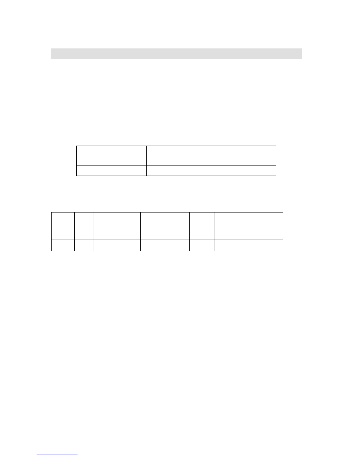
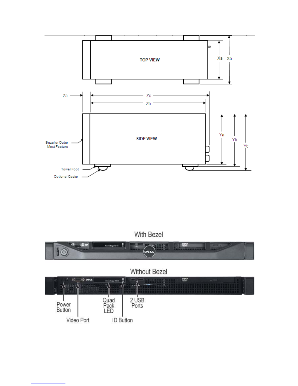
Measurements in Table 6 correspond to the diagram shown in Figure 1 below.
Table 6. Specific Measurements
Xa Xb Ya Yb Yc
Za
with bezel
Za
without
bezel Zb* Zc
L6 Sys
Wgt
(Kg)
PowerEdge R210 Technical Guide 16
Page 17
Dell
Figure 1. Server Dimensions
* Zb goes to the nominal rear wall external surface where the motherboard I/O connectors
reside.
4.3 Front Panel View and Features
PowerEdge R210 Technical Guide 17
Figure 2. Front Panel View
Page 18
Dell
4.4 Back Panel View and Features
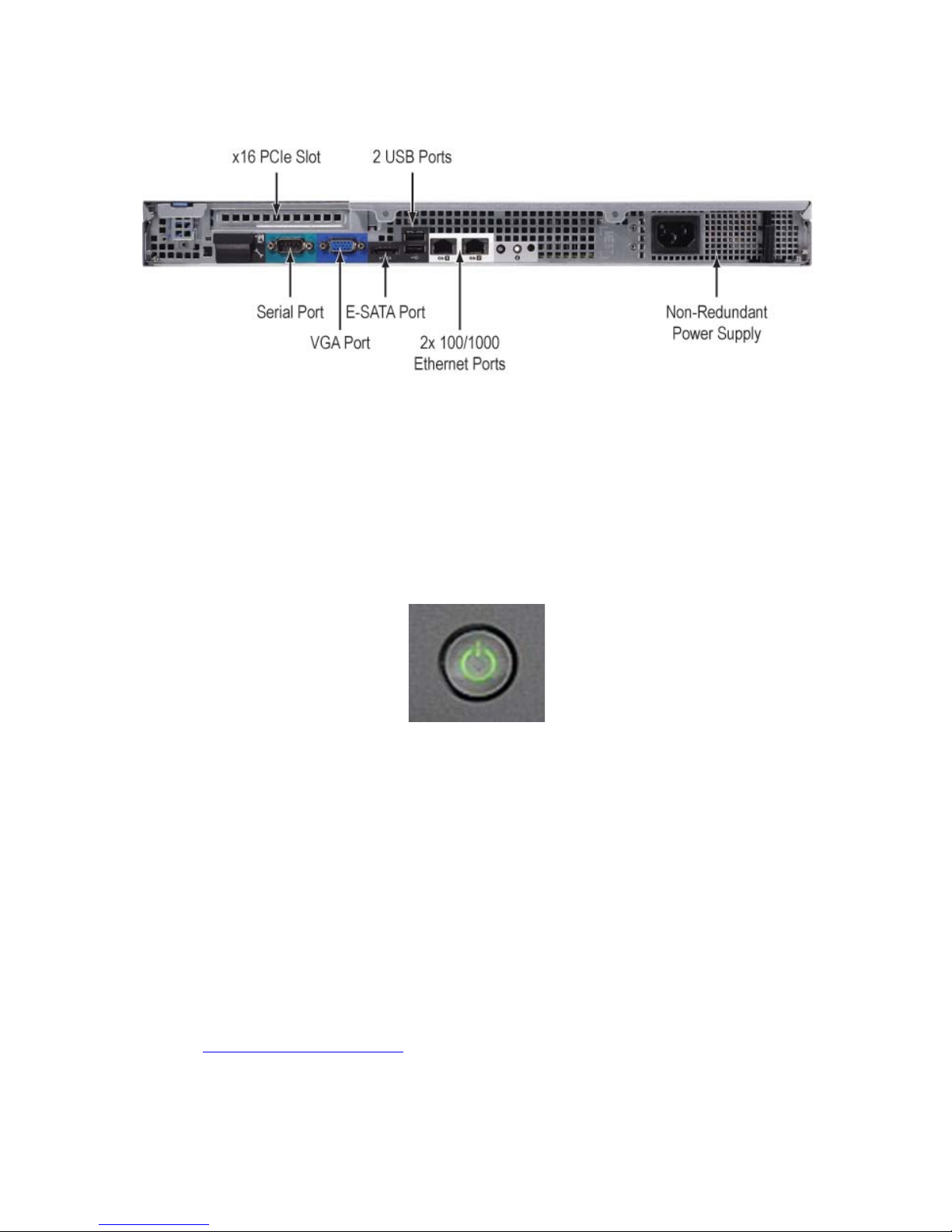
Figure 3. Back Panel View
4.5 Power Supply Indicators
4.5.1 Power Button LED
The Power button controls the system's power, turning the unit on and off.
All PowerEdge servers have the Power LED light-pipe integrated in the Power button. The color
of the power LED is green. The lighting pattern must be in the form of a standard Power icon.
Figure 4. Power Button LED
4.5.2 System Status/ID LED
The System Status/ID LED, present on non-modular rack-dense and rackable tower PowerEdge
servers, has the following states:
• No light—System is in the off state (S5, or mechanical (no AC power)
• Blinking Amber—System fault/error condition.
• Steady Blue—Normal operating state (S0)
• Blinking Blue—System ID engaged
This LED remains powered durin g non-operational (standby, shutdown) modes to enable system
identification.
4.6 NIC Indicators
See the Hardware Owner’s Manual for information.
PowerEdge R210 Technical Guide 18
Page 19
Dell
4.7 Side View
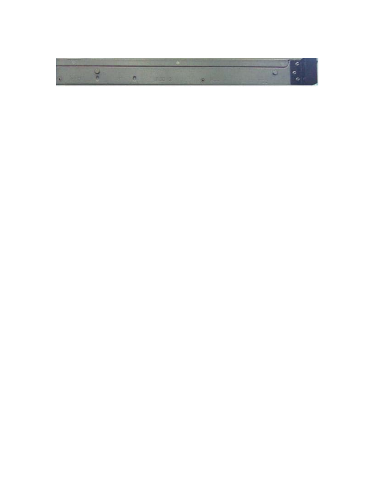
Figure 5. Side View
PowerEdge R210 Technical Guide 19
Page 20

Dell
4.8 Internal Chassis View
PowerEdge R210 Technical Guide 20
Figure 6. Internal Chassis View
Page 21
Dell
4.9 Rails
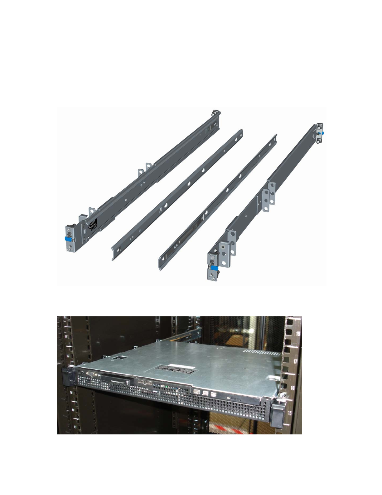
ReadyRails™ static rails for tool-less mounting in 4-post racks with square or
unthreaded round holes or tooled mounting in 4-post threaded and 2-post racks
The R210 rails must first be attached to the sides of the system and then inserted into
the cabinet members installed in the rack. For additional information regarding rail
options for the R210, see Section 13.
Figure 7. R210 Static Rails
Figure 8. R210 Mounted In Four-Post Square-Hole Rack
PowerEdge R210 Technical Guide 21
Page 22
Dell
4.10 Fans
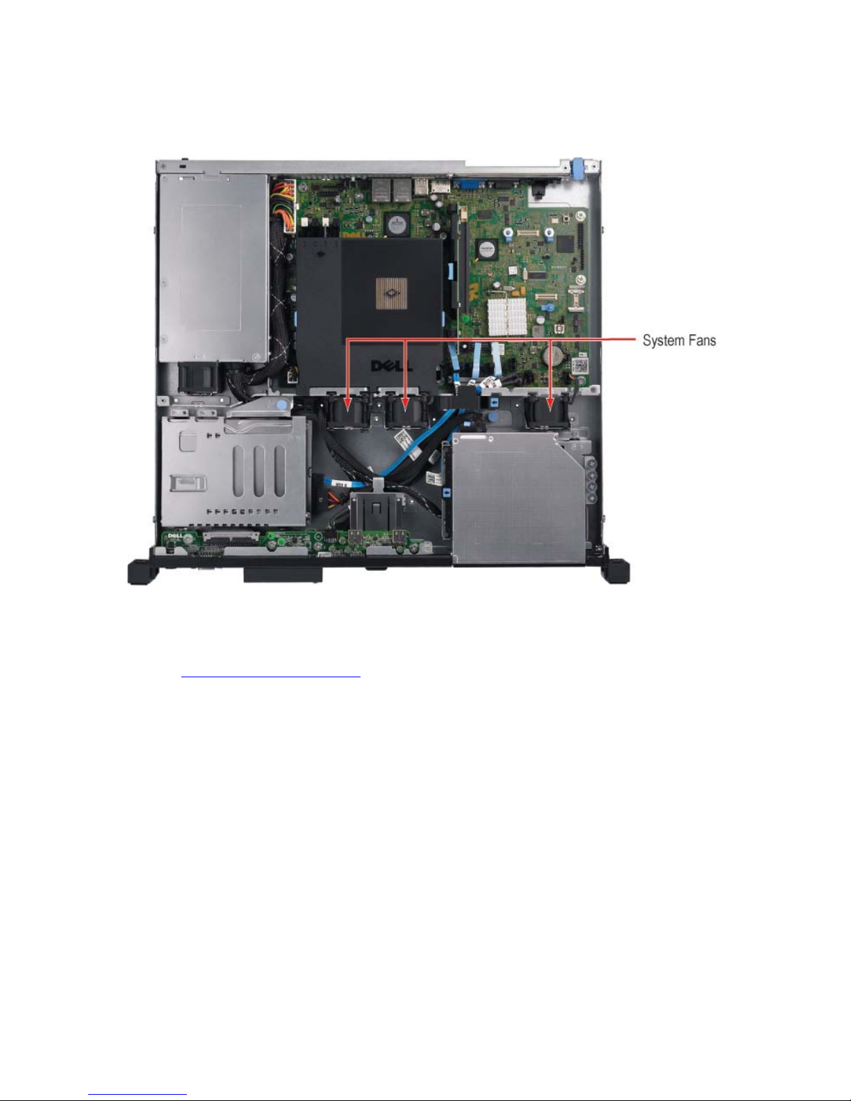
There are three system fans located in the middle of the system.
Figure 9. System Fans
4.11 Control Panel LED
See the Hardware Owner’s Manual for information.
4.12 Security
4.12.1 Top Cover Lock Mechanism
The PowerEdge R210 uses a coin lock on the top cover. This lock must be unlocked and
the cover removed to access the internal components.
4.12.2 Bezel
The bezel lock is located on the front of the bezel and provides security for the system
by preventing access to optical disk drives and the Power button.
4.12.3 Trusted Platform Module (TPM)
The PowerEdge R210 uses a TPM 1.2 compliant encryption chip solution on the system
board with BIOS support worldwide, except for China where Trusted Computing Module
(TCM) is the standard. TPM is disabled by default.
PowerEdge R210 Technical Guide 22
Page 23
Dell
Table 7. TPM Pin Signals
Pin SIGNAL Pin SIGNAL
1 TPM_PRES_N 20 I2C_TPM_SCL
2 LPC_LAD0 19 P3V3
3 GND 18 I2C_TPM_SDA
4 LPC_LAD1 17 LPC_LAD3
5 SEEPROM I2C Address E0 16 GND
6 P3V3_AUX 15 SERIRQ
7 RST_TPM_R_N 14 P3V3
8 LPC_LFRAME_N 13 LPC_LAD2
9 GND 12 GND
10 TPM 33MHz Clock 11 TPM 14MHz Clock
4.12.4 Power Switch Security
The LED control panel is designed so the power switch cannot be accidentally turned
on or off. In addition, in BIOS there is an optional setting in the CMOS setup to disable
the power switch.
4.12.5 Intrusion Alert
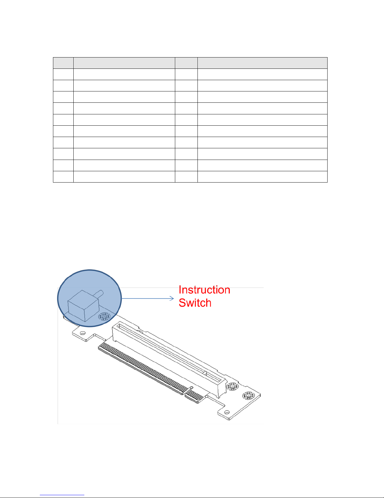
The intrusion switch snaps into the chassis located under the side cover. The intrusion
switch detects and alerts the user that the side cover is open.
Figure 10. Intrusion Switch
PowerEdge R210 Technical Guide 23
Page 24
Dell
4.12.6 Secure Mode
BIOS has the ability to enter a secure boot mode via setup. This mode includes the
option to lock out the power and NMI switches on the control panel or set up a system
password. See the BIOS specification in the
Hardware Owner’s Manual for information.
4.13 USB Ports
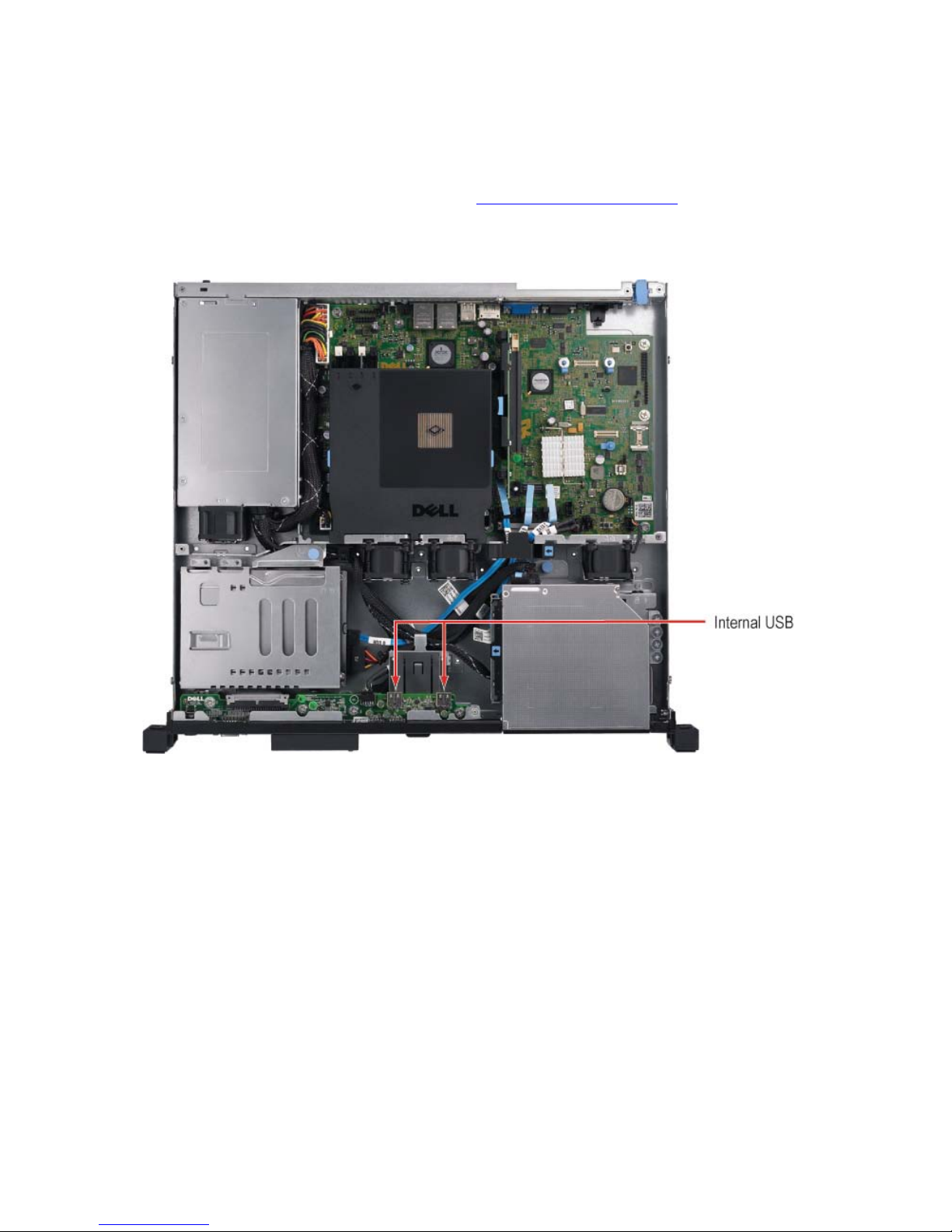
The PowerEdge R210 has two internal USB ports.
Figure 11. Internal USB Ports
4.14 Battery
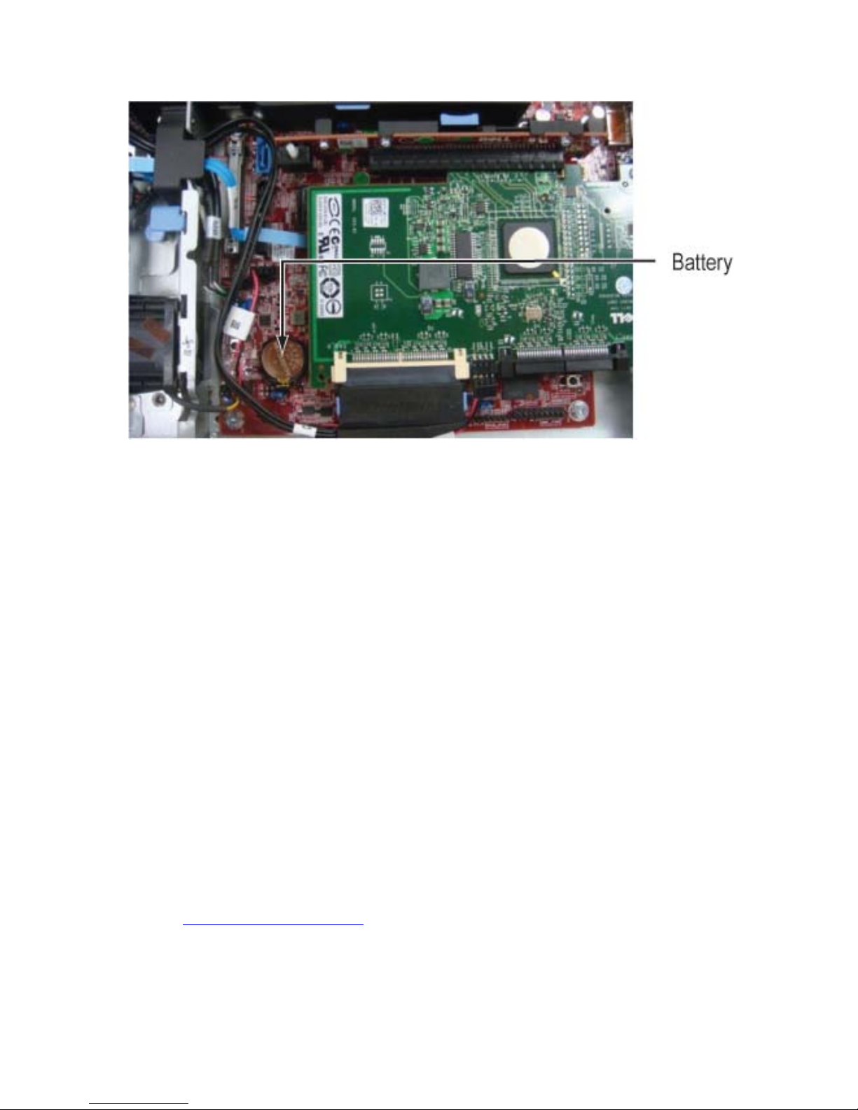
A replaceable lithium battery (CR2032) is mounted on the motherboard to provide
backup power for the real-time clock and CMOS RAM in the Platform Controller Hub
(PCH).
PowerEdge R210 Technical Guide 24
Page 25
Dell
Figure 12. Battery on Motherboard
4.15 Field Replaceable Units (FRU)
The planar contains a 16K x 8 serial EEPROM to store FRU information including Dell part
number, part revision level, and serial number. This information is used by the SEL (system
event log) and the BMC (baseboard management controller).
Parts available for field replace me n t include:
• CMOS battery
• Expansion card
• Front bezel
• HDD
• I/O panel
• Memory
• ODD
• Power supply
• Processor
• Processor shroud
• System board
• System fan
4.16 User Accessible Jumpers, Sockets, and Connectors
See the Hardware Owner’s Manual.
PowerEdge R210 Technical Guide 25
Page 26

Dell
5 P ower, Thermal, Acoustic
5.1 Power Supplies
The base system includes a single 250W power supply. This unit provides power to the planar
and the two internal hard drive bays. Power will be “soft-switched” allowing power cycling
using a switch on the front of the system enclosure or through software control (server
management functions). The power system is compatible with indu stry standards, such as ACPI
and Server 2000.
Standard VRD (Voltage Regulator Down) modules that conform to VRD11.1 specification are
used. This reduces the board layout co mp lexity while offering design modularity. As processor
speeds increase, a newer VRD can be u sed to accommodate the power increase with n o need to
re-spin the board. The VRD is integrated onto the planar and is not field upgradeable.
5.2 Power Supply Connectors on the Planar
There are 2 separate power supply connectors on the planar. One connector is an ATX
connector (2x12) and the other one is a 2x2 connector to provide an additional two pins for
+12V. The connector Pin defin ition (2 x 12 power connector) is not ATX standard.
The 2x12 connector provides 3.3V, 5V, 12V, and 12V standby to the system. (3.3V standby to
system is generated from 12V standby).
Table 8. Power Supply 24 Pins and Signals
Pin SIGNAL Pin SIGNAL
1 P3V3 13 P3V3
2 P3V3 14 P12V1
3 GND 15 GND
4 P5V 16 PS_ON_N
5 GND 17 GND
6 P5V 18 GND
7 GND 19 GND
8 PS_PWROK 20 P12V1
9 P12V_STBY 21 P5V
10 P12V1 22 P5V
11 P12V1 23 P5V
12 P3V3 24 GND
Table 9. Power Supply 4 Pins and Signals
Pin SIGNAL Pin SIGNAL
1 GND 3 P12V2
2 GND 4 P12V2
PowerEdge R210 Technical Guide 26
Page 27

Dell
5.3 Environmental Specificat ions
5.3.1 Temperature
Operating: 10° to 35°C (50° to 95°F) with a maximum temperature gradation of 10°C
per hour (NOTE: For altitudes above 2950 feet, the maximum operating temperature is
de-rated 1ºF/550 ft.)
Storage: –40° to 65°C (–40° to 149°F) with a maximum temperature gradation of 20°C
per hour
5.3.2 Relative Humidity
Operating: 20% to 80% (non-condensing ) wit h a max imu m h u midit y gradation of 10%
per hour
Storage: 5% to 95% (non-condensing)
5.3.3 Maximum Vibration
Operating : 0.26 Grms at 5–350 Hz for 15 min
Storage: 1.54 Grms at 10–250 Hz for 15 min
5.3.4 Maximum Shock
Operating: One shock pulse in the positive z a xis (one pulse on each s ide of the system)
of 31 G for 2.6 ms in the operational orientation
Storage: Six consecutively executed shock pulses in the positive and negative x, y, and
z axes (one pulse on each side of the system) of 71 G for up to 2 ms
Six consecutively executed shock pulses in the positive and negative x, y, and z axes
(one pulse on each side of the system) of 32 G faired square wave pulse with velocity
change at 270 inches/second (686 centimeters/second)
5.3.5 Altitude
Operating: 16 to 3048 m (–50 to 10,000 ft) (Note: For altitudes above 2950 feet, the
maximum operating temperature is de-rated 1ºF/550 ft.)
Storage: 16 to 10,600 m (–50 to 35,000 ft)
5.3.6 Airborne Contaminant Level
Class: G2 or lower as defined by ISA-S71.04-1985
PowerEdge R210 Technical Guide 27
Page 28

Dell
5.4 Power Supply Unit (PSU) Specifications
Table 10. PSU Specifications
Feature Non Redundant PSU
1
L-210
Dimensions
mm x W-106 mm x
H-40.0 mm
Status Indicators
Integrated Fans None
AC Cord Rating
Input Voltage 90 – 264 VAC
Auto-ranging Yes
Line Frequency 47–63 Hertz
Maximum Inrush Current
Hot-Swap Capability No
Output Power 250W
Maximum Heat Dissipation
Efficiency
20% to 100% Load
1
Does not include the power supply handle or ejection tab
1 x bi-color Light Emitting
Diode
15 Amps @ 120 VAC, 10
Amps @ 240 VAC
Under typical line
conditions and over the
entire system ambient
operating range, the inrush
current may reach 25 Amps
for 10 ms or less.
1039 BTU per hour
maximum
82–85% @115 VAC
82–85% @ 230 VAC
5.5 ENERGY STAR® Compliance
See the ENERGY STAR Compliance results on Dell.com.
5.6 Thermal
The thermal design of the PowerEdge R210 reflects the following:
• Closed loop thermal control algorithm. Closed loop thermal control
method uses feedback temperatures to dynamically determine proper fan
speeds.
• Comprehensive thermal management. The PowerEdge R210 controls
system cooling fan speed based on several different responses from critical
components’ sensors, such as CPU temperature, DIMM temperature, inlet
ambient temperature, and system configurations. The thermal management
adjusts proper cooling ability for the system according to what the system
really needs.
PowerEdge R210 Technical Guide 28
Page 29
Dell
°C
• Optimized Ventilation. R210 chassis has a custom ventilation design for
optimized air flow path. Each component and peripheral is ensured
sufficient air to cool.
• Power-to-Cool. Dell continues to improve the design and cooling efficiency
for server products. The power-to-cool ratio of the PowerEdge R210 is
improved over that of its predecessor, PowerEdge R200.
5.7 Acoustics
The acoustical design of the PowerEdge R210 reflects the following:
• Adherence to Dell’s high sound quality standards. Sound quality is
different from sound power level and sound pressure level in that it
describes how humans respond to annoyances in sound, like whistles, hums,
etc. One of the sound quality metrics in the Dell specification is
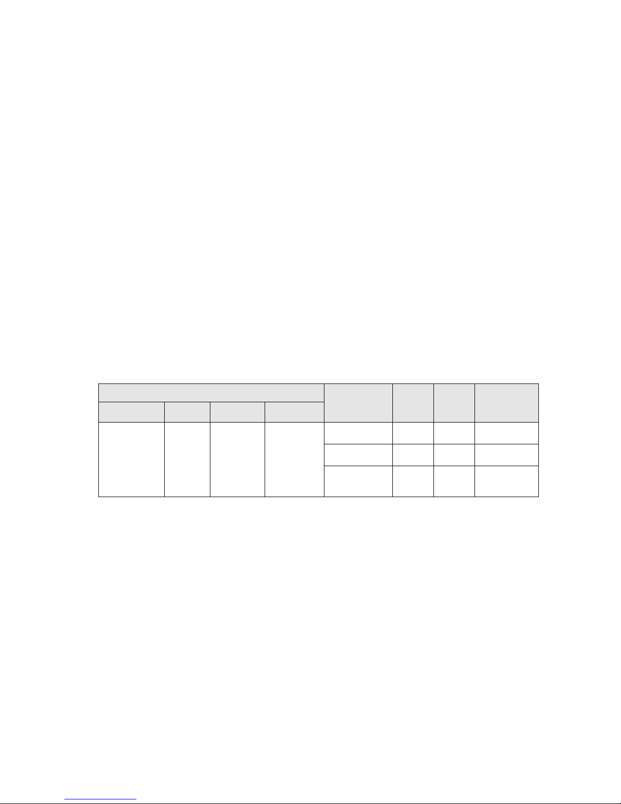
prominence ratio of a tone, as listed in the table below.
• Noise ramp and descent at bootup. Fan speeds, hence noise levels, ramp
during the boot process in order to add a layer of protection for component
cooling in case the system were not to boot properly.
• Noise levels vs. configurations. The noise level of PowerEdge R210 is not
dependent upon the hardware configuration of the system. The table below
shows the noise levels of the PowerEdge R210 with maximum configuration.
Table 11. Acoustical Specifications
Intel® Xeon®
Configurations @ 23 ± 2
CPU DIMM ODD HDD
4 x 3.5” SAS
(450 GB/
15000 RPM)
X3450 2.66
GHz
4 x 4GB
1 X DVD+/-
RW
Operating
Mode
Standby 2.8 16 None
Idle 6.5 49 None
Stressed
Processor
LWA-UL
(Bels)
6.5 49 None
L
pA
(dBA)
PROMINENT
TONES
Definitions
Standby: AC Power is connected to Power Supply Units but system is not turned on.
Idle: Reference ISO7779 (1999) definition 3.1.7; system is running in its OS but no
other specific activity.
Stressed Processor: An operating mode per ISO7779 (1999) definition 3.1.6. The
software MemBW4 is activated to stress the processors.
LwA–UL: The upper limit sound power level (LwA) calculated per section 4.4.2 of ISO
9296 (1988) and measured in accordance to ISO 7779 (1999).
LpA: A-Weighted sound pressure level. The system is placed in a rack with its bottom
at 75 cm from the floor. The acoustic transducer is at front bystander position, ref
ISO7779 (1999) Section 8.6.2.
Prominent tone: Criteria of D.5 and D.8 of ECMA-74 9th ed. (2005) are followed to
determine if discrete tones are prominent. The system is placed in a rack with its
PowerEdge R210 Technical Guide 29
Page 30

Dell
bottom at 75 cm from the floor. The acoustic transducer is at front bystander position,
ref ISO7779 (1999) Section 8.6.2.
PowerEdge R210 Technical Guide 30
Page 31

Dell
6 Processors
6.1 Overview
The PowerEdge R210 is a 1S, entry-level server based on the Intel FCLGA1156 to support Intel
Xeon 3400 series and Core i3 processors.
6.2 Supported Processors
Table 12. Processor Information
Model Speed Power Cache Cores Max.
Memory
Intel® Xeon®
X3430
Intel® Xeon®
X3440
Intel® Xeon®
X3450
Intel® Xeon®
X3460
Intel® Xeon®
X3470
Intel® Xeon®
L3426
Intel® Core™
i3 540
Intel® Core™
i3 530
Intel®
Pentium
G6950
Intel®
Celeron
G1101
®
®
2.4GHz 95W 8M 4C 1333MHz
2.53GHz 95W 8M 4C 1333MHz
2.67GHz 95W 8M 4C 1333MHz
2.8GHz 95W 8M 4C 1333MHz
2.93GHz 95W 8M 4C 1333MHz
1.86GHz 45W 8M 4C 1333MHz
3.06GHz 73W 4M 2C 1333MHz
2.93GHz 73W 4M 2C 1333MHz
2.8GHz 73W 3M 2C 1066MHz
2.26GHz 73W 2M 2C 1066MHz
Intel® Xeon®
L3406
2.26GHz 30W 4M 2C 1066MHz
6.3 Processor Configurations
The PowerEdge R210 is a single socket 1U r ack server that operates in single processor mode
only. The memory controller is embedded in the processor.
PowerEdge R210 Technical Guide 31
Page 32

Dell
Memory
7 Memory
7.1 Overview
Features of the PowerEdge R210 memory include:
• 2 channels per processor
• Support for Unbuffered ECC DDDR3 DIMMs.
• Support for DDR3 speeds of 1066/1333
• 4 DIMM sockets (16GB Maximum capacity)
• Support for Single Rank and Dual Rank DIMMs
7.2 DIMMs Supported
The following DIMMs are supported by the PowerEdge R210:
• 1GB, DDR3 UDIMM, 1066 w/ECC
• 1GB, DDR3 UDIMM, 1333 w/ECC
• 2GB, DDR3 UDIMM, 1066 w/ECC
• 2GB, DDR3 UDIMM, 1333 w/ECC
• 4GB, DDR3 UDIMM, 1066 w/ECC
• 4GB, DDR3 UDIMM, 1333 w/ECC
Table 13. Supported Processor Configurations
System
System
Capacity
1GB 1066 1066 UDIMM 1 1 1 1 X8
1GB 1333 1333 UDIMM 1 1 1 1 X8
2GB 1066 1066 UDIMM 1 2 1,2 1 X8
2GB 1333 1333 UDIMM 1 2 1,2 1 X8
4GB 1066 1066 UDIMM 1 4 1,2,3,4 1 X8
4GB 1066 1066 UDIMM 2 2 1,2 2 X8
4GB 1333 1333 UDIMM 1 4 1,2,3,4 1 X8
4GB 1333 1333 UDIMM 2 2 1,2 2 X8
Speed
DIMM
Speed
DIMM_T
ECH
DIMM
Capacity
NUM_DI
MM Slot
NUM_
Rank
Data
Width
8GB 1066 1066 UDIMM 2 4 1,2,3,4 2 X8
8GB 1066 1066 UDIMM 4 2 1,2 2 X8
8GB 1333 1333 UDIMM 2 4 1,2,3,4 2 X8
8GB 1333 1333 UDIMM 4 2 1,2 2 X8
16GB 1066 1066 UDIMM 4 4 1,2,3,4 2 X8
PowerEdge R210 Technical Guide 32
Page 33

Dell
Memory
System
System
Capacity
16GB 1333 1333 UDIMM 4 4 1,2,3,4 2 X8
2GB 1066 1066 UDIMM 2 1 1 2 X8
2GB 1333 1333 UDIMM 2 1 1 2 X8
4GB 1066 1066 UDIMM 4 1 1 2 X8
4GB 1333 1333 UDIMM 4 1 1 2 X8
Speed
DIMM
Speed
DIMM_T
ECH
DIMM
Capacity
NUM_DI
MM Slot
NUM_
Rank
Data
Width
7.3 Slots/Risers
The PowerEdge R210 planar provides four 72-bit (240-pin) sockets for DIMM memory
modules. These modules are DDR3-800/1066/1333 Unbuffered DDR SDRAM DIMMs. The
modules are configured as 72 bits wide to provide for ECC. The memory controller in
the CPU performs the ECC. The system supports a minimum of 1GB upgradeable to 16
of RAM, using the following DIMM sizes:
• 1GB, DIMM Module
• 2GB, DIMM Module
• 4GB, DIMM Module
7.4 Speed
The PowerEdge R210 supports 1066/1333MHz DDR3 memory.
7.5 Sparing
Not supported.
7.6 Mirroring
Not supported.
7.7 RAID
Memory RAID is not supported.
PowerEdge R210 Technical Guide 33
Page 34

Dell
8 Chipset
8.1 Overview
The PowerEdge R210 planar incorporates the Intel Ibex Peak as PCH chipset. The Ibex
Peak is a highly integrated I/O controller. The high-level features supported by the
chipset and implemented on the PowerEdge R210 are detailed in the sections that
follow.
8.2 Direct Media Interface
Direct Media Interface (DMI) is the chip-to-chip connection between the processor and Ibex
Peak chipset. This high-speed interface integrates advanced priority-based servicing allowing
for concurrent traffic and true isochronous transfer capabilities. Base functionality is
completely software-transparent, permitting curr e n t and legacy software to operate normally.
8.3 PCI Express Interface
The Ibex Peak provides up to 8 PCI Express Root Ports, supporting the PCI Express Base
Specification, Revision 2.0. Each Root Port supports 2.5 GB/s bandwidth in each direction (5
GB/s concurrent). PCI Express Root Ports 1-4 can be statically configured as four x1 Ports or
ganged together to form one x 4 p or ts. Ports 5 and 6 can only be used as two x 1 port.
8.4 SATA Interface
The Ibex Peak has two integrated SATA host controllers that support independent DMA
operation on up to six ports and supports data transfer rates of up to 3.0 GB/s (300MB/s). The
SATA controller contains two modes of operation – a legacy mode using I/O space, and an AHCI
mode using memory space. Software that uses legacy mode will not have AHCI cap abilities.
The Ibex Peak supports the Serial ATA Specification, Revision 1.0a. The Ibex Peak also supports
several optional sections of the Serial ATA II: Extensions to Serial ATA 1.0 Specification,
Revision 1.0 (AHCI support is r e q uired for some elements).
8.5 AHCI
The Ibex Peak provides hardware support for Advanced Host Controller Interface (AHCI), a new
programming interface for SATA host controllers. Platforms supporting AHCI may take
advantage of performance features such as no master/slave designation for SATA devices—each
device is treated as a master—and hardware-assisted native command queuing. AHCI also
provides usability enhancements such as Hot-Plug. AHCI requires appropriate software support
(e.g., an AHCI driver) and for some features, hardware support in the SATA device or additional
platform hardware.
8.6 PCI Interface
The Ibex Peak PCI interface provides a 33 MHz, Revision 2.3 implementation. The Ibex Peak
integrates a PCI arbiter that supports up to four external PCI bus masters in addition to the
internal Ibex Peak requests. This allows for combinations of up to four PCI down devices and
PCI slots.
PowerEdge R210 Technical Guide 34
Page 35

Dell
8.7 Low Pin Count (LPC) Interface
The Ibex Peak implements an LPC Interface as described in the LPC 1.1 Specification. The Low
Pin Count (LPC) bridge function of the Ibex Peak resides in PCI Device 31:Function 0. In
addition to the LPC bridge interface function, D31:F0 contains other functional units including
DMA, interrupt controllers, timers, power management, system management, GPIO, and RTC.
8.8 Serial Peripheral Interface (SPI)
The Ibex Peak implements an SPI Interface as an alternative interface for the BIOS flash device .
An SPI flash device can be used as a replacement for the FWH, and is required to support
Gigabit Ethernet, Intel
Technology. The Ibex Peak supports up to two SPI flash devices with speed up to 20 MHz, 33
MHz utilizing two chip select pins.
®
Active Management Technology and integrated Intel Quiet System
8.9 Compatibility Module
The DMA controller incorporates the logic of two 82C37 DMA controllers, with seven
independently programmable channels. Channels 0–3 are hardwired to 8-bit, count-by-byte
transfers, and channels 5–7 are hardwired to 16-bit, count-by-word transfers. Any two of the
seven DMA channels can be program me d to support fast Type-F transfers.
Channel 4 is reserved as a generi c b us master request.
The Ibex Peak supports LPC DMA, which is similar to ISA DMA, through the Ibex Peak’s DMA
controller. LPC DMA is handled through the use of the LDRQ# lines from peripherals and special
encoding on LAD[3:0] from the host. Single, Demand, Verify, and Increment modes are
supported on the LPC interface.
The timer/counter block contains three counters that are equivalent in function to those found
in one 82C54 programmable interval timer. These three counters are combined to provide the
system timer function, and speaker tone. The 14.31818 MHz oscillator input provides the clock
source for these three counters.
The Ibex Peak provides an ISA-Compatible Programmable Interrupt Controller (PIC) that
incorporates the functionality of two, 82C59 interrupt controllers. The two interrupt
controllers are cascaded so that 14 external and two internal interrupts are possible. In
addition, the Ibex Peak supports a serial interrupt scheme.
All of the registers in these modules can be read and restored. This is required to save and
restore system state after power has been removed and restored to the platform.
8.10 Advanced Programmable Interrupt Controller (APIC)
In addition to the standard ISA compatible Programmable Interrupt controller (PIC) described in
the previous section, the Ibex Peak incorporates the Advanced Programmable Interrupt
Controller (APIC).
8.11 USB Interface
The Ibex Peak contains up to two Enhanced Host Controller Interface (EHCI) host controllers
that support USB high-speed signaling. High-speed USB 2.0 allows data transfers up to 480 Mb/s
which is 40 times faster than full-speed USB. The Ibex Peak also contains up to seven Universal
Host Controller Interface (UHCI) controllers that support USB full-speed and low-speed signaling.
The Ibex Peak supports up to fourteen USB 2.0 ports. All fourteen ports are high-speed, fullspeed, and low-speed capable. Ibex Peak’s port-routing logic determines whether a USB port is
controlled by one of the UHCI or EHCI controllers.
PowerEdge R210 Technical Guide 35
Page 36

Dell
8.12 Real-Time Clock (RTC)
The Ibex Peak contains a real-time clock with 256 bytes of battery-backed RAM.
The real-time clock performs two key functions: keeping track of the time of day and storing
system data, even when the system is powered down. The RTC operates on a 32.768 KHz
crystal and a 3 V battery.
The RTC also supports two lockable memory ranges. By setting bits in the configuration space,
two 8-byte ranges can be locked to read and write accesses. This prevents unauthorized
reading of passwords or other system security information.
The RTC also supports a date alarm that allows for scheduling a wake up event up to 30 days in
advance, rather than just 24 hours in advance.
8.13 GPIO
Various general purpose inputs and outputs are provided for custom system design. The number
of inputs and outputs varies depe nding on Ibex Peak configuration.
8.14 Enhanced Power Management
The Ibex Peak’s power management functions include enhanced clock control and various lowpower (suspend) states (e.g., Suspend-to-RAM and Suspend-to-Disk). A hardware-based thermal
management circuit permits software-independent entrance to low-power states. The Ibex
Peak contains full support for the Advanced Configuration and Power Interface (ACPI)
Specification, Revision 3. 0a.
8.15 System Management Features
In addition to Intel AMT, the Ibex Peak integrates several functions designed to
manage the system and lower the total cost of ownership (TCO) of the system. These
system management functions are designed to report errors, diagnose the system, and
recover from system lockups without the aid of an external microcontroller.
8.15.1 TCO Timer
The Ibex Peak’s integrated programmable TCO (Total Cost of Ownership) timer is used
to detect system locks. The first expiration of the timer generates an SMI# that the
system can use to recover from a software lock. The second expiration of the timer
causes a system reset to recover from a hardware lock.
8.15.2 Processor Present Indicator
The Ibex Peak looks for the processor to fetch the first instruction after reset. If the
processor does not fetch the first instruction, the Ibex Peak will reboot the system.
8.15.3 Error Code Correction (ECC) Reporting
When detecting an ECC error, the host controller has the ability to send one of several
messages to the Ibex Peak. The host controller can instruct the Ibex Peak to generate
an SMI#, NMI, SERR#, or TCO interrupt.
PowerEdge R210 Technical Guide 36
Page 37

Dell
8.15.4 Function Disable
The Ibex Peak provides the ability to disable the following integrated functions: LAN,
USB, LPC, Intel HD Audio, SATA, PCI Express or SMBus. Once disabled, these functions
no longer decode I/O, memory, or PCI configuration space. Also, no interrupts or
power management events are generated from the disabled functions.
Intruder Detect. The Ibex Peak provides an input signal (INTRUDER#) that can be
attached to a switch that is activated by the system case being opened. The Ibex Peak
can be programmed to generate an SMI# or TCO interrupt due to an active INTRUDER#
signal.
8.16 System Management Bus (SMBus 2.0)
The Ibex Peak contains an SMBus Host interface that allows the processor to
communicate with SMBus slaves. This interface is compatible with most I2C devices.
Special I2C commands are implemented.
The Ibex Peak’s SMBus host controller provides a mechanism for the processor to
initiate communications with SMBus peripherals (slaves). Also, the Ibex Peak supports
slave functionality, including the Host Notify protocol. Hence, the host controller
supports eight command protocols of the SMBus interface (see System Management Bus
(SMBus) Specification, Version 2.0): Quick Command, Send Byte, Receive Byte, Write
Byte/Word, Read Byte/Word, Process Call, Block Read/Write, and Host Notify.
Ibex Peak’s SMBus also implements hardware-based Packet Error Checking for data
robustness and the Address Resolution Protocol (ARP) to dynamically provide address
to all SMBus devices.
8.17 Intel Anti-Theft Technology
The Ibex Peak introduces a new hardware-based security technology which encrypts
data stored on any SATA compliant HDD in AHCI Mode. This feature gives the end-user
the ability to restrict access to HDD data by unknown parties. Intel Anti-Theft
Technology can be used alone or can be combined with software encryption
applications to add protection against data theft.
Intel Anti-Theft Technology functionality requires a correctly configured system,
including an appropriate processor, Intel Management Engine firmware, and system
BIOS support.
8.18 Intel Virtualization Technology for Directed I/O
The Ibex Peak provides hardware support for implementation of Intel Virtualization
Technology with Directed I/O (Intel VT-d). Intel VT-d Technology consists of
technology components that support the virtualization of platforms based on Intel
Architecture Processors. Intel VT-d Technology enables multiple operating systems and
applications to run in independent partitions. A partition behaves like a virtual
machine (VM) and provides isolation and protection across partitions. Each partition is
allocated its own subset of host physical memory.
PowerEdge R210 Technical Guide 37
Page 38

Dell
8.19 JTAG Boundary-Scan
Ibex Peak adds the industry standard JTAG interface and enables Boundary-Scan in
place of the XOR chains used in previous generations of the Ibex Peak. Boundary-Scan
can be used to ensure device connectivity during the board manufacturing process.
The JTAG interface allows system manufacturers to improve efficiency by using
industry available tools to test the Ibex Peak on an assembled board. Since JTAG is a
serial interface, it eliminates the need to create probe points for every pin in an XOR
chain. This eases pin breakout and trace routing and simplifies the interface between
the system and a bed-of-nails tester.
PowerEdge R210 Technical Guide 38
Page 39

Dell
9 BIOS
9.1 Overview
The following features are supported by BIOS:
• System BIOS
• System Setup
• Onboard PCI video BIOS support
• SATA enabled for CDROM and HDD
• PCI FW3.0 compliant
• PCI-to-PCI bridge 1.0 compliant
• Plug and Play BIOS 1.0a compliant
• MP 1.4
• SMBIOS 2.5
• USB 1.1 with legacy USB support
• USB 2.0 support in BIOS during pre-boot
• Dell Server Assistant 7.0 support
• System Service support
• iDRAC supported
• Error logging via ESM
• ACPI 2.0 support (S0, OS-S4, S5 states)
• I2O v1.5 ready
• Selectable Boot support based on BIOS Boot Specif i cat i on v1.01
• CD-ROM Boot 1.0
• Remote BIOS Update support
• Remote Configuration Interface (RCI) su pport
• Console redirection via COM1
• PXE support based on Preboot Execution Environment Specification v2.1
• 2-byte ID support
• ePPID support in flash
• Memory remapping support
• DDR3 UDIMM memory support
• UEFI shell Support
• IDRAC6/IDRAC6 Lite support
• VT-d
• IOAT
PowerEdge R210 Technical Guide 39
Page 40

Dell
RTC
S5, OS-S4
Power Button
S5, OS-S4
RI#
Not supported
USB
Not supported
WOL
S5, OS-S4
• AC recovery staggering Power-Up
• DIMM mismatch checking
• Support for multiple power profiles:
• Static Maximum Performance Mode
• OS Control (DBS)
• Active Power Controller
• Custom
9.2 ACPI
ACPI compliance: S0, S4, S5 supported
NO S1, S2, S3 (STR) support.
S4 will be supported by OS support only.
Table 14. Wake Up Events and States
Wake Up Events States Can Wake From
PME# S5, OS-S4
KB Not supported
MOUSE Not supported
9.3 Power Management Modes
9.3.1 Dell Active Power Controller
The Dell Active Power Controller (DAPC) is a Dell proprietary implementation that
provides improved performance/watt over the OS implementation of Intel’s DBS. DAPC
is implemented in system BIOS and uses hardware level counters, etc. to determine
hardware utilization. The BIOS uses this information to determine when to change the
processor’s operating frequency. The DAPC is OS independent and means that the OS
no longer has control. This provides a consistent power management solution
regardless of the installed OS. Some OS(s), particularly hypervisors, do not support
power management, thus DAPC provides a solution when there otherwise would not be
one.
PowerEdge R210 Technical Guide 40
Page 41

Dell
Feature
Type
Enable/Status
Description
ACPI mode
Fixed
PCH
The OS uses the SCI_EN bit to switch from
Sleep states
Fixed
PCH
Supported states: S0(Working), S4-OS
Real-Time
Fixed
PCH
The OS is able to configure the system to wake
9.3.2 Power Saving BIOS Setting (OS Control)
Intel processors support Demand Based Switching (DBS) which enables the processor to
dynamically change its operating frequency in response to workload changes. The
industry standard implementation of this power management feature is in the
Operating System (OS). The OS monitors process/thread level utilization of the
processor and uses processor controls to change the processor’s operating frequency.
For heavy workloads, the OS will run the processor at higher frequencies for additional
performance. Lighter workloads do not need high performance, thus the OS will run
the processor at lower frequencies.
9.3.3 Maximum Performance
The Maximum Performance Mode disables power management. In this mode, the
processor frequency is statically set to the highest supported frequency.
The power management features are implemented via two categories: fixed or
generic. Fixed features use bits defined in the ACPI specification for specific
capabilities. The fixed feature bits give the OS complete control over the power
management of a device since the location of the bits is given to the OS in the FACP
table. Thus, a driver can directly access bits to control a device’s power management.
Generic features have defined enable and status bits, but the functionality is not fully
visible to the OS. Dell provides ASL code to handle the details of generic features,
allowing the OS to intelligently communicate with system-specific hardware.
Table 15. Summary of R210 Power Management Features
/Ctrl bit
location
switch
Power Button Fixed PCH In ACPI mode, OS has control of the power
Clock
Power Mgmt.
Timer
Power Mgmt.
Event (PME)
Fixed PCH 24-bit power management timer is u sed.
Generic PCH Each host bus’s PME# signal is routed to a
legacy mode to ACPI mode.
(‘Hibernation’ in W2K), and S5 (Soft-off).
S1 (also called ‘standby’ or ‘suspend’) and S3
are not supported.
button. In non-ACPI mode, SMI handler owns
power button events.
on the RTC alarm.
separate general-purpose event pin in the
chipset. When a device signals P ME#, the system
wakes (if necessary), the OS detects the event,
and a Dell defined ASL routine handles the
event. Wake-on-LAN is one example of a PME.
PowerEdge R210 Technical Guide 41
Page 42

Dell
USB wake
Generic
N/A
This feature is not supported on t h is system
C State
N/A
Processor and
This feature allows multiple C state supports for
Power Profile
N/A
Processor/IMC
11G Servers will be the most energy smart
Maximum Performance
DBPM Disabled ( BIOS will set P-State to MAX)
OS Control
Enable OS DBPM Control (BIOS will expose
Active Power Controller
Enable DellSystem DBPM (BIOS will not make all P states
Custom
CPU Power and Performance Management
since the S1 state is not supported.
DBS N/A Processor
MSRs
Support
support
PCH registers
and PCH
chipset
registers.
Table 16. Power Profiles that R210 BIOS will Expose in BIOS Setup
This feature does P state transition under
Windows
Processor. This feature will work under
Windows and ACPI OS that understand C states.
servers that Dell will ship. In addition to P,C
and T states, BIOS will expose th e Power
Profiles to the OS. Each Power profile will have
a specific settings and it will fine tune
processor, MCH, IOH and South Bridge. For
detailed explanation on how this feature works,
please look at BIOS Power Management
specification located in Design Docs under R310
engineering.
Memory frequency = Maximum Performance
Fan algorithm = Maximum Perf ormance
all possible P states to OS)
Memory frequency = Maximum Performance
Fan algorithm = Minimum Power
available to OS)
Memory frequency = Maximum Performance
Fan algorithm = Minimum Power
:
Maximum Performance | Min imum Power | OS DBPM | System
DBPM
Memory Power and Performance Management:
Maximum Performance |1333Mhz |1067Mhz |800Mhz|
Minimum Power
Fan Algorithm
Maximum Performance | Minimum Po wer
PowerEdge R210 Technical Guide 42
Page 43
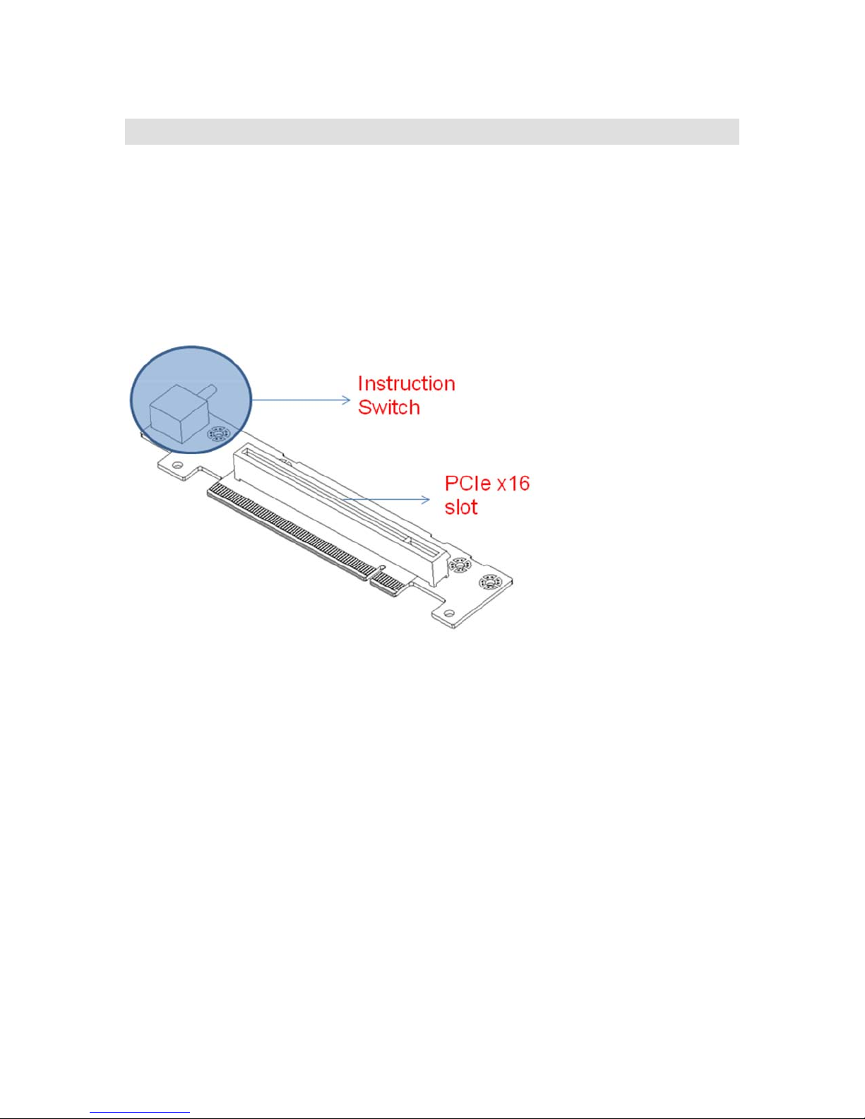
Dell
10 I/O Slots
10.1 Overview
The PowerEdge R210 system provides:
• Riser support x16 PCIe card (Gen2 link x16)
• Support x16 bandwidth card under 25W
Figure 13. PCIe x16 Riser Card
PowerEdge R210 Technical Guide 43
Page 44
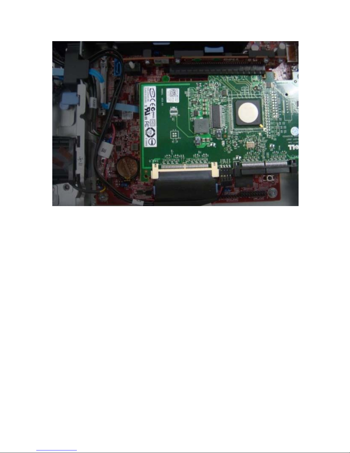
Dell
Figure 14. SAS 6/iR Adapter Card Installed
10.2 PCI Devices
Xeon 3400 Series CPU PCI devices include:
• Intel QuickPath Architecture Generic Non-core Registers
• Intel QuickPath Architecture System Address Decoder
• Intel QuickPath Interconnect Link 0
• Intel QuickPath Interconnect Physical 0
• Integrated Memory Controller General Registers
• Integrated Memory Controller Target Address Decoder
• Integrated Memory Controller Test Registers
• Integrated Memory Controller Channel 0 Control
• Integrated Memory Controller Channel 0 Address
• Integrated Memory Controller Channel 0 Rank
• Integrated Memory Controller Channel 0 Thermal Control
• Integrated Memory Controller Channel 1 Control
• Integrated Memory Controller Channel 1 Address
• Integrated Memory Controller Channel 1 Rank
• Integrated Memory Controller Channel 1 Thermal Control
• DMI Root Port
• PCI Express Root Port 1
• PCI Express Root Port 3
PowerEdge R210 Technical Guide 44
Page 45

Dell
• Core Addressing Mapping, Intel VT-d, System Management
• Core Semaphore and Scratchpad Registers
• Core System Control/Status Registers
• Core Miscellaneous Control/Status Registers
• Intel QuickPath Interconnect Link
• Intel QuickPath Interconnect Routing and Protocol
Core i3/Pentium/Celeron CPU PCI devices include:
• Host Bridge/DRAM Controller
• Host-to-PCI Express Bridge
• Internal Graphics Device
• Secondary Host–to-PCI Express Bridge
PCH and Slots devices include:
• Virtualization Engine Controller Interface (VECI)
• USB HS EHCI Controller #2
• PCI Express Port 1
• PCI Express Port 2
• PCI Express Port 3
• PCI Express Port 4
• PCI Express Port 5
• PCI Express Port 6
• PCI Express Port 7
• PCI Express Port 8
• USB HS EHCI Controller #1
• DMI-to-PCI Bridge
• LPC Controller1
• SATA Controller #1
o Non-AHCI and Non-RAID Mode (Ports 0,1, 2 and 3)
o Desktop Non-AHCI and Non-RAID Mode (Ports 0 and 1)
o AHCI Mode (Ports 0-5)
o AHCI Mode (Ports 0,1,4 and5)
o RAID 0/1/5/10 mode
• SMBus Controller
• SATA Controller #2
o Non-AHCI and Non-RAID Mode (Ports 4 and 5)
• Thermal Subsystem
• Slot 1 PCI-E x16 [IIO]
• BCM5716 (1)
• BCM5716 (2)
®
• Matrox
G200eW w/ 8MB memory
The onboard devices are SATA, USB (x4), SMBus, IOxAPIC, and the LOM.
PCI Slot # Mechanical Electrical Height Length
1 PCIe x 16 PCIe x 16 Gen 2 Full Half
PowerEdge R210 Technical Guide 45
Table 17. I/O Slot Information
Page 46

Dell
Link Width Height Length
Table 18. PCI Card Dimensions
x1 Standard height, half
length card
X1, x4,
x8, x16
Standard height, full
length cards
Low profile cards 68.90 mm (2.731 inches)
111.15 mm (4.376
inches) max
111.15 mm (4.376
inches) max
max
167.65 mm (6.600 inches
max
312.00 mm (12.283
inches) max
167.65 mm (6.600 inches )
max
Table 19. Bandwidth, Quantities, and Priorities
Category Description Bandwidth Max
Qty.
Internal Storage
Controllers
External Storage
Controllers
Dell™ SAS 6iR Adapter (SASRAID)
Dell™ PERC S300 (SW RAID) PCIe x8 1 1
Dell™ PERC H200 (HW RAID) PCIe x8 1 1
Dell™ SAS 5E Adapter PCIe x8 1 1
Dell™ PERC 6E Adapter 256MB PCIe x8 1 1
Dell™ PERC 6E Adapter 512MB PCIe x8 1 1
PCIe x8 1 1
Slot
Priority
Optional NICs
6Gbps SAS HBA PCIe x8 1 1
Dell™ PERC H800 PCIe x8 1 1
Dell™ LSI2032 PCIe HBA SCSI
Adapter
Intel® Gigabit ET Dual Port
Server Adapter
Broadcom® NetXtreme™ II 5709
Dual Port Ethernet PCIe Card
with TOE
Broadcom® NetXtreme™ II 5709
Dual Port Ethernet PCIe Card
with TOE and iSCSI Offload
Intel® PRO/1000 PT Server
Adapter
Intel® Gigabit ET Quad-Port
Server Adapter
Broadcom® NetXtreme™ II
BCM5709 Quad Port Ethernet
PCIe™ Card with TOE and iSCSI
Offload
PCIe x4 1 1
PCIe x4 1 1
PCIe x4 1 1
PCIe x4 1 1
PCIe x1 1 1
PCIe x4 1 1
PCIe x4 1 1
PowerEdge R210 Technical Guide 46
Page 47

Dell
10.3 Boot Order
The PowerEdge R210 supports only 1 PCIe x8 slot.
10.4 NICs
There is Broadcom 5716 chip on the PowerEdge R210 motherboard. The chip is connected to
the PCH via a PCI Express x4 gen2 link. Broadcom 5716 does not support TOE (TCP Offload
Engine).
The chip provides two Gigabit Ethernet po rts. There are two RJ-45 connectors with inte grated
magnetic and LE D on the rear of the system. The firmware for the LOM chip resides in a flash
part.
The PowerEdge R210 supports Wake on LAN (WOL) from either port.
For listing of NICs supported on the R210, please see Section 10.1 Table 24
PowerEdge R210 Technical Guide 47
Page 48

Dell
11 Storage
11.1 Overview
The PowerEdge R210 supports up to 2 HDDS:
• 2 x 2.5”/ 3.5” cabled SATA or SSD from motherboard SATA connec tor
• 2 x 2.5”/ 3.5” cabled SAS, SSD, or SATA via add-on storage controller
Customer must be selected at point of purchase. This is not an upgrade option for
APOS.
11.2 Drives
Table 20. Available Drives
Drive Specifications
HDD Bays 2 x 3.5" or 2 x 2.5”
Cabled only
HDD/SATA 3.5"/7.2K: 160, 250, or 1000GB, 2000GB
HDD/Near Line SAS 3.5"/7.2K: 1000GB, 2000GB
HDD/SAS 3.5”/15K: 146, 300, or 45 0G B, 600GB
3.5”/10K: 600GB
2.5”/10K: 146 or 300GB
HDD/SSD
2.5”: or 50GB, 100GB
PowerEdge R210 Technical Guide 48
Page 49

Dell
11.3 RAID Configurations
Table 21. RAID Configurations
Non-Mixed
Drives, all SATA,
all SSD, or ALL
SAS
Config
Type
No HDD 0 NCZCBL No controller/No hard drive 0 0
SATA – No
Raid
SATA Raid 2 MSTR0CBL Embedded SATA SW RAID – RAID0 2 2
SAS/SATA
RAID
Configs
# Name
1 MSTCBL On-board SATA Controller (Ibex Peak) 1 2
3 MSTR1CBL Embedded SATA SW RAID – RAID1 2 2
4 ASSCBL Add-in SAS/SATA RAID card, No RAID
5 ASSCBL Add-in SAS/SATA RAID card, No RAID
6 ASSR0CBL Add-in SAS/SATA RAID card, RAID 0 (S300) 2 2
7 ASSR1CBL Add-in SAS/SATA RAID card, RAID 1 (S300) 2 2
8 ASSCBL Add-in SAS/SATA RAID card, No RAID (SAS
Description Min
HDD
1 1
(S300)
2 2
(S300) with 2 HDDs
1 2
6/iR /H200 )
Max
HDD
9 ASSR0CBL Add-in SAS/SATA RAID card, RAID 0 (SAS
10 ASSR1CBL Add-in SAS/SATA RAID card, RAID 1 (SAS
11.4 Optical Disk Drive (ODD)
The PowerEdge R210 will support up to 1 slim type internal optical drive and optional
external USB DVD-ROM. The PowerEdge R210 can boot from either the internal optical
drive or the optional external drive and supports the following:
• Configurations with no ODD
• Optional internal DVD-ROM (SATA)
• Optional internal DVD+RW (SATA)
PowerEdge R210 Technical Guide 49
2 2
6/iR /H200)
2 2
6/iR/H200 )
Page 50

Dell
11.5 Tape Drives
Table 22. Supported Tape Drives
PowerVault™ MD1000
PV DAS
External TBU
External TBU/Automation
PowerVault™ MD3000
PowerVault™ MD1120
PowerVault™ RD1000
PowerVault™ 114X
PowerVault™ DAT 72
PowerVault™ LTO-3-060
PowerVault™ 110T LTO-3
PowerVault™ LTO4-120
PowerVault™ ML6000
PowerVault™ 124T
PowerVault™ TL2000/TL4000
PowerEdge R210 Technical Guide 50
Page 51

Dell
12 Video and Audio
12.1 Video
Matrox® G200eW w/ 8MB memory integrated in Winbond® WPCM450 (BMC controller):
• 640x480 (60/72/75/85 Hz; 8/16/32-bit color)
• 800x600 (60/72/75/85 Hz; 8/16/32-bit color)
• 1024x768 (60/70/75/85 Hz; 8/16/32-bit color)
• 1280x1024 (60/75/85 Hz; 8/16-bit color)
• 1280x1024 (60 Hz, 32-bit color)
12.2 Audio
The PowerEdge R210 does not support aud io (sound card or speakers).
PowerEdge R210 Technical Guide 51
Page 52
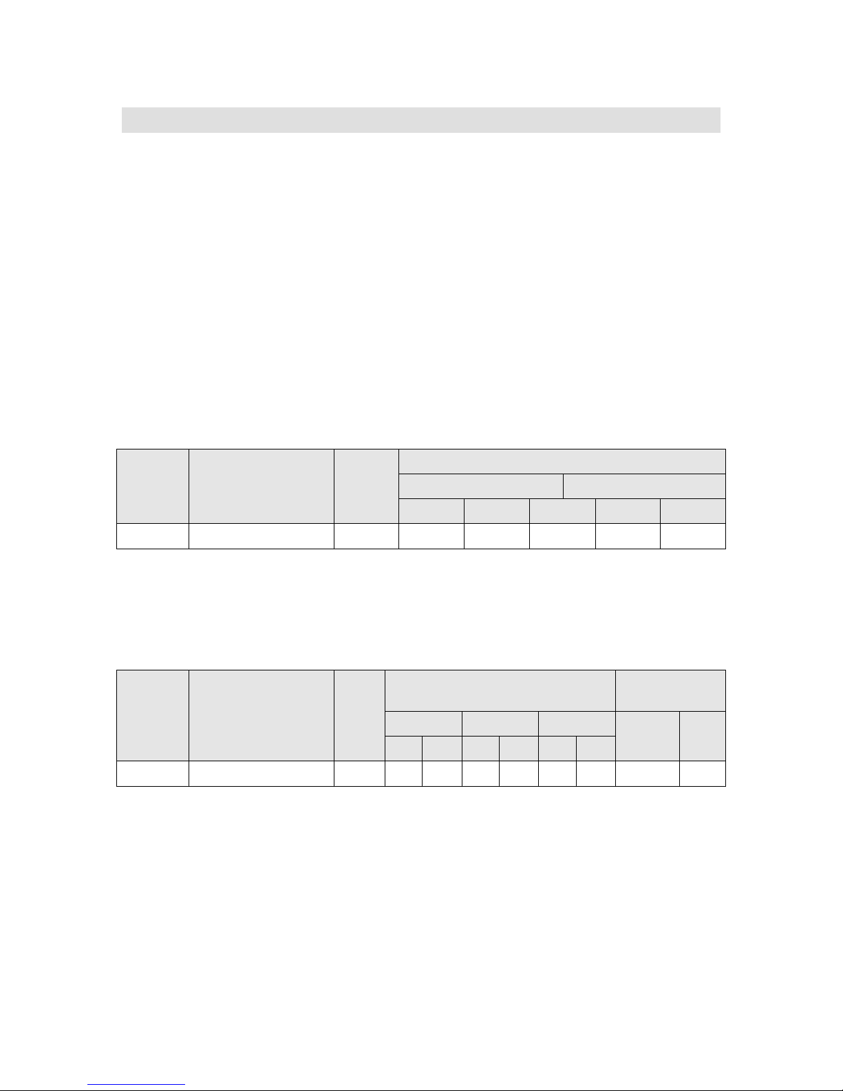
Dell
13 Rack Information
13.1 Overview
The ReadyRails™ static rail system for the R210 provides tool-free support for racks
with square or unthreaded round mounting holes (including Dell’s 42xx and 24xx series
racks) with an adjustment range of 60–87 cm. The rails also offer tooled mounting
support for 4-post threaded and 2-post (Telco) racks for added versatility.
13.2 Rails
The static rails for the R210 support tool-less mounting in 19”-wide, E IA -310-E
compliant square hole and unthreaded round hole racks via Dell’s ReadyRails™
mounting interface. The rails also support a “generic” mounting interface for tooled
mounting in threaded hole and 2-post (Telco) racks. Screws are not included in the kit
since threaded racks are offered with a variety of thread designations. Users must
provide their own screws when mounting the rails in threaded or 2-post racks.
Table 23. PowerEdge R210 Rail Information
Rail
Identifier
A4 ReadyRails™/Generic Static Yes Yes Yes Yes Yes
Mounting Interface Rail
Type
Rack Types Supported
4-Post 2-Post
Square Round Thread Flush Center
The adjustment range of the rails is a function of the type of rack in which they are
being mounted. The min-max values listed below represent the allowable distance
between the front and rear mounting flanges in the rack.
Figure 15. Rack Adjustability Range
Rail
Identifier
A4 ReadyRails™/Generic Static 608 879 594 872 604 890 622 —
Mounting Interface Rail
Type
Rack Adjustability Range (mm) Rail Depth
(mm)
Square Round Threaded Without
Min Max Min Max Min Max
CMA
With
CMA
13.3 Cable Management Arm (CMA)
The static rails for the R210 support a wide variety of racks and mounting
configurations but do not support the ability to extend the system out of the rack for
service. Thus, they do not provide support for a cable management arm (CMA).
PowerEdge R210 Technical Guide 52
Page 53

Dell
14 Operating Systems
For the most up-to-date information, see the Operating System Support Matrix for Dell
PowerEdge Systems on Dell.com.
Table 24. Supported Microsoft Operating Systems
Operating
Systems
Windows®
Essential
Business
Server
Microsoft®
Hyper-V™
Server 2008
Windows
Small
Business
Server 2008
Windows
Server
Windows
Server
R2
®
®
2008
®
2003
x86 or x64 Installation Factory
Install
Standard
X64
X64 Standard Download N/A
X64
x32-bit x86
x64
(Hyper-V™ role
enabled except
for foundation)
32-bit x86
x64
Premium
Standard
Premium
Web
Standard
Enterprise
Web
Standard
Foundation
Enterprise
Standard
Enterprise
Standard
Enterprise
DIB N/A
FI N/A
Test Only WHQL
Test Only WHQL
Test Only WHQL
Test Only WHQL
Logo/
Certification
X86
Windows
®
2008
Server
SP2
Windows
Server® 2008
R2 (Windows
7 includes
SP2 bits)
X64
(Hyper-V™ role
enable)
X64 (only)
(Hyper-V™ role
enabled except
for foundation)
PowerEdge R210 Technical Guide 53
Web
Standard
Enterprise
Web
Standard
Enterprise
Web
Standard
Foundation
Enterprise
FI
FI
WHQL
(WLK1.4)
WHQL
(WLK1.4)
Page 54

Dell
Table 25. Supported Linux Operating Systems
Operating
Systems
Red Hat®
Enterprise
®
4.8
Linux
Red Hat®
Enterprise
®
5.3
Linux
Novell®
®
Linux®
SUSE
Enterprise
S10 SP3
Novell®
®
Linux®
SUSE
Enterprise
S11
x86 or x64 Installation Factory
Install
Logo/
Certification
x86-64 ES DIB, NFI Yes
x86 ES DIB, NFI Yes
x86-64 Enterprise FI Yes
x86 Enterprise DIB, NFI Yes
x86-64 ES DIB, NFI Yes
X86-64 ES FI Yes
PowerEdge R210 Technical Guide 54
Page 55

Dell
15 Virtualization
Table 26. Supported Virtualization OS
Virtualization OS Install Method
VMware® ESX 4 update 1 DIB
Embedded VMware ESXi 4 update
1
VMWare ESX 3.5.1 Supported; not offered
VMWare ESXi 3.5.1 Supported; not offered
PlateSpin® PowerConvert®
Vizioncore™ suite:
vRanger™ Pro
vConverter™
vReplicator
vFoglight™
Download version
through Dell (No FI nor DIB)
through Dell (No FI or DIB)
Website download
fulfillment; instructions are
DIB
Website download
fulfillment; instructions are
DIB
PowerEdge R210 Technical Guide 55
Page 56

Dell
16 Systems Management
16.1 Overview
Dell delivers open, flexible, and integrated solutions that help you reduce the
complexity of managing disparate IT assets by building comprehensive IT management
solutions. Combining Dell PowerEdge Servers with a wide selection of Dell-developed
management solutions gives you choice and flexibility, so you can simplify and save in
environments of any size. To help you meet your server performance demands, Dell
offers Dell OpenManage systems management solutions for:
• Deployment of one or many servers from a single management console
• Monitoring of server and storage health and maintenance
• System update, configuration change, and maintenance
Dell offers IT management solutions for organizations of all sizes—priced, sized, and
supported right.
16.2 Server Management
A Dell Systems Management and Documentation DVD and a Dell Management Console
DVD are included with the product. Content includes:
• Dell Systems Build and Update Utility: Dell Systems Build and Update
Utility assists in OS install and pre-OS hardware configuration and updates.
• OpenManage Server Administrator: The OpenManage Server Administrator
(OMSA) tool provides a comprehensive, one-to-one systems management
solution, designed for system administrators to manage systems locally and
remotely on a network. OMSA allows system administrators to focus on
managing their entire network by providing comprehensive one-to-one
systems management.
• Management Console: Our legacy IT Assistant console is also included, as
well as tools to allow access to our remote management products. These
tools are Remote Access Service for iDRAC and the BMC Management Utility.
• Active Directory Snap-in Utility: The Active Directory Snap-in Utility
provides an extension snap-in to the Microsoft Active Directory. This allows
you to manage Dell specific Active Directory objects. The Dell-specific
schema class definitions and their installation are also included on the DVD.
• Dell Systems Service Diagnostics Tools: Dell Systems Service and
Diagnostics tools deliver the latest Dell optimized drivers, utilities, and
operating system-based diagnostics that you can use to update your system.
• eDocs: The section includes PDF files for PowerEdge systems, storage
peripheral, and OpenManage software.
• Dell Management Console DVD: The Dell Management Console is a Web-
based systems management software that enables you to discover and
inventory devices on your network. It also provides advanced functions,
such as health and performance monitoring of networked devices and patch
management capabilities for Dell systems.
PowerEdge R210 Technical Guide 56
Page 57

Dell
• Server Update Utility: In addition to the Systems Management Tools and
Documentation and Dell Management Console DVDs, customers have the
option to obtain Server Update Utility DVD. This DVD has an inventory tool
for managing updates to firmware, BIOS, and drivers for either Linux or
Windows operating systems.
16.3 Embedded Server Management
The PowerEdge R210 implements circuitry for the next generation of embedded server
management. It is Intelligent Platform Management Interface (IPMI) v2.0 compliant.
The optional iDRAC (Integrated Dell Remote Access Controller) is responsible for acting
as an interface between the host system and its management software and the
periphery devices. These periphery devices consist of the PSUs, the storage backplane,
integrated SAS HBA or PERC 6/I, and control panel with display.
The optional upgrade to iDRAC6 provides features for managing the server remotely or
in data center lights-out environments.
Advanced iDRAC features require the installation of the optional iDRAC6 Enterprise
card.
16.4 Lifecycle Controller and Unified Server Configurator
Embedded management is comprised of four key components:
• Dell Lifecycle Controller
• Dell Unified Server Configurator
• iDRAC6 (Integrated Dell Remote Access Controller)
• vFlash (virtual flash media)
Lifecycle Controller powers the embedded management features. It is integrated and
tamperproof storage for system-management tools and enablement utilities (firmware,
drivers, etc.).
Dell Unified Server Configurator (USC) is a local 1:1 graphical user interface embedded
on Lifecycle Controller that aids in local server provisioning in a pre-OS environment.
For servers with iDRAC Express, the Lifecycle Controller offers OS install, platform
updates, platform configuration, and diagnostics capabilities. For servers without
iDRAC6 Express, this utility has limited functionality and offers OS install and
diagnostics capabilities only.
To access the Unified Server Configurator, press the <F10> key within 10 seconds of
the Dell logo’s appearance during the system boot process. Current functionality
enabled by the Unified Server Configurator is detailed in the following table.
PowerEdge R210 Technical Guide 57
Page 58

Dell
Table 27. Unified Server Configurator Features and Description
Feature Description
Faster O/S Installation Drivers and the installation utility are
embedded on system
Faster System Updates Integration with Dell support automatically
directed to latest versions of t he Unified
Server Configurator, iDRAC, RAID, BIOS, NIC,
and Power Supply
Update Rollback Ability to recover to previou s k nown good
state for all updatable components
More Comprehensive Diagnost ics Diagnostic utilities are embedded on system
Simplified Hardware Configuration Detects RAID controller and allows user to
configure virtual disk and cho ose virtual disk
as boot device, eliminating th e need to launch
a separate utility. Also provides configuration
for iDRAC, BIOS, and NIC/LOM.
16.5 iDRAC6 Express
The optional iDRAC6 Express is the first tier of iDRAC6 upgrades. In addition to
upgrading the system with a Lifecycle Controller, the iDRAC6 Express offers the
following key features:
• Graphical web interface
• Standard-based interfaces
• Server Sensor monitoring and fault alerting
• Secure operation of remote access functions including authentication,
authorization, and encryption
• Power control and management with the ability to limit server power
consumption and remotely control server power states
• Advanced troubleshooting capabilities
For more information on iDRAC6 Express features see table below.
16.6 iDRAC6 Enterprise
The optional iDRAC6 Enterprise card provides access to advanced iDRAC6 features. The
iDRAC6 Enterprise connects directly to the R210 planar and i s mounted p arallel to the
planar with stand-offs.
Key features for the iDRAC6 Enterprise include:
• Scripting capability with Dell’s Racadm command-line
• Remote video, keyboard, and mouse control with Virtual Console
• Remote media access with Virtual Media
• Dedicated network interface
Additionally, the iDRAC6 Enterprise can be upgraded by adding the vFlash Media card.
This is a 1 GB Dell branded SD card that enables a persistent 256 or 512 MB virtual
PowerEdge R210 Technical Guide 58
Page 59

Dell
flash partition. A more detailed feature list for iDRAC6 Enterprise and vFlash is
included in the following table.
Table 28. Features List for BMC, iDRAC6, and vFlash
iDRAC6
Feature BMC iDRAC6 Express
Interface and Standards Support
Enterprise vFlash Media
IPMI 2.0
Web-based GUI
SNMP
WSMAN
SMASH-CLP
Racadm command-
line
Conductivity
Shared/Failover
Network Modes
IPv4
VLAN Tagging
IPv6
Dynamic DNS
Dedicated NIC
Security and Authentication
Role-based
Authority
Local Users
Active Directory
SSL Encryption
Remote Management and Remediation
Remote Firmware
Update
Server power
control
Serial-over-LAN
(with proxy)
Serial-over-LAN (no
proxy)
Power capping
Last crash screen
PowerEdge R210 Technical Guide 59
Page 60

Dell
capture
Feature BMC iDRAC6 Express
iDRAC6
Enterprise vFlash Media
Boot capture
Serial-over-LAN
Virtual media
Virtual console
Virtual console
sharing
Virtual flash
Monitoring
Sensor Monitoring
and Alerting
Real-time Power
Monitoring*
Real-time Power
Graphing*
Historical Power
Counters*
Logging Features
System Event Log
RAC Log
Trace Log
* BMC availability through OpenManage
PowerEdge R210 Technical Guide 60
Page 61

Dell
17 Peripherals
17.1 USB
All PowerEdge systems have a minimum of 2 front-accessible USB 2.0 compliant ports
with enough spacing around to accommodate full usage of both connectors
simultaneously along with any/all other front panel features (Video connector,
buttons, LED’s, etc.) without mechanical interference. These ports are connected to
the same controller and not shared with internal or back USB ports
For security reasons, all external USB ports must have an enable/disable function.
Disabling USB controllers must observe the hierarchy in Table 29 (listed from lowest to
highest priority in a 4 controller design).
Internal USB ports connected to internal persistent storage devices have an
enable/disable function independent of the other ports present in the system.
Table 29. USB Controller Priorities
USB Controller Function If Disabled
4 (Lowest) Internal USB peripherals No other Controller is disabled
3 Front USB Controller 4 is disabled as well
2 Back USB Controllers 3 & 4 are disabled as well
1 (Highest) Remote Access (RAC) Controllers 2,3, & 4 are disabled as well
The above hierarchy dictates that connections that are lower in the hierarchy must be
disabled anytime a higher level connection is disabled (e.g., when Back USB is disabled
the Front USB ports are also disabled).
17.2 USB Device
Optional external USB DVD-ROM.
PowerEdge R210 Technical Guide 61
Page 62

Dell
17.3 External Storage
Table 30. External Storage
External Optical Drive (Opt ional) USB DVD-ROM
MD1000 JBOD
PowerVault™ DAS
External TBU
External TBU/Automation
MD3000 RBOD
MD1120 – 2.5 SAS/SATA JBOD
RD1000 USB
PV114T (2U)
DAT 72 SCSI
LTO3-060 SCSI
LTO3FH SCSI
LTO4-120 HH and FH SAS
ML6000
PV124T
TL2000
TL4000
PowerEdge R210 Technical Guide 62
Page 63

Dell
INSIDE DIMENSIONS
OUTSIDE DIMENSIONS
WEIGHT
Length: 61.9 cm (24.38”)
Length: 63.5 cm (25.00”)
System packed out weight:
18 Packaging Options
Options for single pack and mul t ip ack are available. Multipack will support 4 units in one pack.
Table 31. AMF Single Pack Dimensions and Weights
Length: 81.3 cm (32”)
Width: 59.4 cm (23.38”)
Depth: 23.5 cm (9.25”)
Length: 82.9 cm (32.63”)
Width: 61 cm (24”)
Depth: 26.7 cm (10.5”)
System packed out weight:
PowerEdge R210: 9.71 kg (21.42
lbs)
Cushion: 0.42 kg (.93 lbs)
Corrugated Box: 2.75 kg (6.05
lbs)
Total Weight: 12.88 kg (28.4 lbs)
Table 32. EMF Single Pack Dimensions and Weights
INSIDE DIMENSIONS OUTSIDE DIMENSIONS WEIGHT
Width: 59.4 cm (23.38”)
Depth: 24.1 cm (9.50”)
Width: 61 cm (24”)
Depth: 27.3 cm (10.75”)
PowerEdge R210: 8.56 kg (18.87
lbs)
Cushion: 0.36 kg (.80 lbs)
Corrugated Box: 2.06 kg (4.55
lbs)
Total Weight: 10.98 kg (24.2 lbs)
PowerEdge R210 Technical Guide 63
Page 64
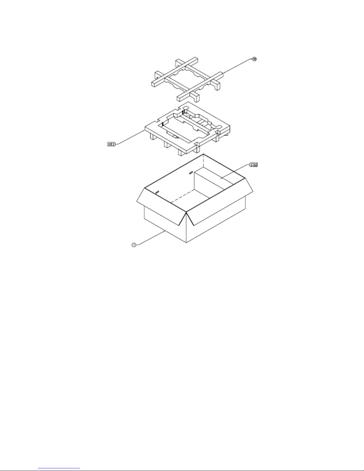
Dell
Figure 16. Packaging
PowerEdge R210 Technical Guide 64
Page 65

Dell
Appendix A. Regulatory Certifications
• FCC (U.S. only) Class A
• ICES (Canada) Class A
• CE Mark (EN 55022 Class A, EN55024, EN61000-3-2, EN61000-3-3)
• VCCI (Japan) Class A
• BSMI (Taiwan) Class A
• C-Tick (Australia/New Zealand) Class A
• NRCS/SABS (South Africa) Class A
• CCC (China) Class A
• KCC (Korea) Class A
• UL 60950-1
• CAN/CSA C22.2 No. 60950-1
• EN 60950-1
• IEC 60950-1
• IRAM (Argentina)
• NOM (Mexico)
• Bellis (Belarus)
• Koncar (Croatia)
• TUV GS (Germany)
• SII (Israel)
• CKT (Kazakhstan)
• KEBS (Kenya)
• INSM (Moldova)
• Soncap (Nigeria)
• Nemko (Norway)
• GOST (Russia)
• KVALITET (Serbia, Bosnia, H e r zegovina, Montenegro)
• UKRTEST (Ukraine)
• UZBEKISTAN GOST (Uzbekistan)
• KUCAS (Kuwait)
• KSA-ICCP (Saudi Arabia)
• MPT (Vietnam)
PowerEdge R210 Technical Guide 65
Page 66

Dell
Appendix B. R210 V olatility Tables
Table 33. PowerEdge R210 Volatility
ReferNonVol-
Planar
atile
Volatile
RAM
ence
Design
-ator
Q
t
y Size Type
System BIOS
SPI Flash
LOM
Configuration
Data
iDRAC6
Controller
ROM
iDRAC6
Controller
RAM
System CPLD
System CPLD
iDRAC6
Express
Internal
Flash
Y
Y
Y
Y
Y
Y
Y
SYS_S
PI
U7
U_IBM
C1
U_IBM
C1
U_CPL
D1
U_CPL
D1
U_EM
MC
1 4MB
1 512KB FLASH (NOR)
1 4KB ROM
1 8KB RAM
1 1200 Macro cells Internal Flash EEPROM
1 1KB RAM
1 1GB NAND FLASH
Flash EEPROM (SPI
interface)
Y
System RAM
TPM ID
EEPROM
(Plug in
module only)
TPM Binding
EEPROM (on
China planar
only)
PowerEdge R210 Technical Guide
Y
Y U21 1 256B EEPROM
DIMM_
A1,
DIMM_
A2,
DIMM_
B1,
DIMM_
B2
U_SEE
PROM
up to 4 DIMMs 16GB RAM
4
1 256B EEPROM
66
Page 67
Dell
NonVolatile
Volatile
RAM
Refer-
ence
Design
-ator
Q
t
y Size Type
iDRAC6
SDRAM Y
U_IBM
C_MEM
iDRAC6 FRU
Y
iDRAC6 Boot
Block Flash Y
U_IBM
C_FRU
IBMC_
SPI
Trusted
Platform
Y N
U_TPM1 1 128 bytes EEPROM
Module
Chipset
CMOS
Y
U_PCH
1
Control Panel
Internal USB
Y
USB3
USB4
iDRAC6 Enterprise
vFlash Y J_SD
(conne
ctor) 1 1GB
1 128MB DDR2 RAM
1 4KB EEPROM
1
16MB
FLASH (NOR)
1 256B Battery-backed RAM
User selectable
2
License key hard set
ROM or user choice
Secure Digital NAND
Flash
PowerEdge R210 Technical Guide
67
Page 68

Dell
Table 34. Volatility: Data Writing and Purpose
Can user programs or
operating system write
data to it during normal
operation?
Planar
System BIOS
SPI Flash
No Not used
LOM
Configuration
NO iDRAC Internal RAM
Data
iDRAC6
Controller ROM
iDRAC6
controller RAM
System CPLD
(non-volatile)
No System-Specific Hardware Logic
No Not used
No for iDRAC Operating
System; Yes for Managed
System Services
Repository
System CPLD
(volatile)
Yes System OS RAM
iDRAC6 Express
Internal Flash
No Not used
Purpose?
iDRAC Operating System plus Managed System
Services Repository (i.e., Unified Server
Configurator, OS drivers, d iag nostics, rollback
versions of various programmables)
System RAM
NO iDRAC internal RAM
TPM ID
EEPROM (Plug
in module
No
BIOS binding of plug in module to a particular
planar.
only)
TPM Binding
EEPROM (China
No BMC OS + VGA frame buffer
only)
iDRAC6 SDRAM No motherboard electronic prod u ct identifier
iDRAC6 FRU
No
iDRAC boot loader and configur at ion (i.e. MAC
address), Lifecycle log.
nd system event log.
iDRAC6 Boot
Block Flash
Trusted
Platform
Module
yes Storage of encryption keys
No
BIOS binding of plug-in module to a particular
planar
PowerEdge R210 Technical Guide
68
Page 69

Dell
Can user programs or
Purpose?
operating system write
data to it during normal
operation?
Chipset
CMOS
Control Panel
Internal USB
iDRAC6
Enterprise
No BIOS settings
Yes as allowed by OS
Normal usage is read only soft ware license
key, but not limited
vFlash Yes when enabled,
installed, and the media
does not have the write
Storage of logs, user images such as files,
drivers, and Operating Systems
protect switch applied
Table 35. Methodology for Data Input to Memory
How is data input to this memory?
Planar
System BIOS SPI Flash Loading flash memory requires a vendor-provided firmware file and
loader program which is execut e d b y booting the system from a
floppy or OS-based executable contain ing the firmware file and the
loader. System loaded with arbitr ar y data in firmware memory will
not operate
LOM Configuration
Data
Loading flash memory requires a vendor-provided firmware file and
loader program which is execut e d b y booting up the system from a
floppy or OS based executable containing the firmware file and the
loader. LOMs loaded with arbitrary d ata in firmware memory will not
operate.
iDRAC6 Controller
RAM
iDRAC embedded system
System CPLD Loading flash memory r e quires a vendor-provided firmware file and
loader program which is execut e d b y booting up the system from a
floppy or OS-based executable (currently only DRMK utility support)
containing the firmware fil e an d the loader. System loaded with
arbitrary data in CPLD memory will not operate.
iDRAC6 Express
Internal Flash
Not used
iDRAC OS: Loading flash memory requires a vendor-provided firmware
file and loader program which i s e xecuted by booting the system from
a floppy or OS-based executable con taining the firmware file and the
loader. System loaded without a good iDRAC firmware image yields a
System RAM
non-functional iDRAC.
PowerEdge R210 Technical Guide
69
Page 70

Dell
How is data input to this memory?
Managed Services Repository: Various partitions are loaded using
vendor-provided firmware file an d loader program just like iDRAC OS.
TPM ID EEPROM (Plugin module only)
TPM Binding EEPROM
(on China planar only)
iDRAC6 SDRAM
Factory loaded only
BIOS only
Embedded iDRAC OS for 108MB and 8MB for VGA frame buffer
iDRAC6 FRU Factory and iDRAC embedded OS
iDRAC6 Boot Block
Flash
Loading flash memory requires a vendor-provided firmware file and
loader program which is executed by booting up the sy ste m fr om a
floppy or OS-based executable or out of b and firmware updates
across the management network. Bad contents yield the iDRAC
inoperable and unrecoverable in the customer environment. The
lifecycle log is automatically updated by the iDRAC as various system
component firmware, hardware, and software versions change.
Trusted Platform
Module
Using TPM-enabled operating systems; exce p t in China where TCM is
used.
Chipset
CMOS BIOS control only via input such as BIOS F2 menu user configuration
settings (such as boot order)
Control Panel
Internal USB Either read only license key or OS control copies
iDRAC6 Enterprise
vFlash Preloaded media before installation, or remote out-of-band upload of
user data (i.e., ISO images, files) or local server read/write capability
to use like a hard disk.
PowerEdge R210 Technical Guide
70
Page 71

Dell
Table 36. Methodology for Memory Protection and Clearing
How is this
memory
write
Planar
protected? How is the memory cleared?
System BIOS SPI
Flash
LOM
Configuration
Data
iDRAC6
Controller ROM
iDRAC6
controller RAM
System CPLD
(non-volatile)
System CPLD
(volatile)
Software
write
protected
Not possible with any utilitie s or applications and system
is not functional if corrupte d /r emoved.
No explicitly
protected but
special
applications
are needed to
communicate
Not user clearable
through the
LOMs to
reprogram
this ROM
protected
permanently
Not clearable
by hardware
n/a iDRAC reset
Requires
special system
specific utility
Not possible with any utilitie s or applications and system
is not functional if corrupte d /r emoved.
Not accessible Not clearable
iDRAC6 Express
Internal Flash
Writes are
proxied
through a
temporary
iDRAC
scratchpad
RAM and not
directly made
from an OS or
OS application
System RAM
OS control Reboot or power down system
TPM ID EEPROM
(Plug in module
HW read only Not clearable, read only
only)
PowerEdge R210 Technical Guide
Not user clearable
71
Page 72

Dell
TPM Binding
EEPROM (on
China planar
only)
iDRAC6 SDRAM
iDRAC6 FRU writes
iDRAC6 Boot
Block Flash
Trusted
Platform Module
Chipset
CMOS
Locked by
BIOS from
physical
access by
anyone after
boot
n/a
controlled by
iDRAC
embedded OS
iDRAC
embedded OS
control of the
write
protection
SW write
protected
N/A, BIOS
only control
Not applicable, BIOS control only
AC cycle for BMC OS and reset/power o ff ser ver for VGA
frame buffer
EPPID is not clearable
Not possible with any utilitie s or applications and iDRAC
does not function as expected if corrupted/removed.
Lifecycle log is clearable only in a factory environment;
System Event Log is user clearable
F2 Setup option
Planar NVRAM_CLR jumper or by r e moval of AC cord,
cover, and coin cell battery, then waiting 30 seconds prior
to replacement of battery, cover and AC cord.; F2 system
setup option is used to restore de faults
Control Panel
Internal USB
iDRAC6 Enterprise
vFlash Media write
OS control OS control format
protection
switch or OS
control
iDRAC-based format, local OS format, del e ted, or card
removed and formatted on a client
PowerEdge R210 Technical Guide
72
 Loading...