

Dell External OEMR T610, PowerEdge T610 Technical Manual

PowerEdge T610
Technical Guide
The PowerEdge
T610 server
delivers balanced
high performance,
energy efficiency
and room for
growth.

Dell
This document is for informational purposes only. Dell reserves the right to make changes without
further notice to any products herein. The content provided is as is and without express or implied
warranties of any kind.
Dell, PowerEdge, Dell OpenManage, and ReadyRails are trademarks of Dell, Inc. Citrix is a registered
trademark and XenServer is a trademark of Citrix Systems, Inc. and/or one or more of its
subsidiaries, and may be registered in the United States Patent and Trademark Office and in other
countries. Intel, Xeon, and SpeedStep are registered trademarks and MMX is a trademark of Intel
Corporation in the U.S. and other countries. Broadcom is a registered trademark and NetXtreme is a
trademark of Broadcom Corporation and/or its affiliates in the United States, certain other countries
and/or the EU. Emulex is a registered trademark of Emulex Corporation. ENERGY STAR is a registered
trademark of the U.S. Environmental Protection Agency. eToken is a trademark of Aladdin Knowledge
Systems, Ltd. Linux is a registered trademark of Linus Torvalds. Matrox is a registered trademark of
Matrox Electronic Systems Ltd. Microsoft, Windows, Windows Server, SQL Server, Hyper-V, and
BitLocker are either registered trademarks or trademarks of Microsoft Corporation in the United
States and/or other countries. Novell and SUSE are registered trademarks of Novell, Inc., in the
United States and other countries. Oracle is a registered trademark and Solaris is a trademark of
Oracle Corporation and/or its affiliates. Red Hat is a registered trademark of Red Hat, Inc. in the
United States and other countries. Symantec is a trademark owned by Symantec Corporation or its
affiliates in the U.S. and other countries. VMware is a registered trademark and vSphere is a
trademark of VMware, Inc. in the United States and/or other jurisdictions. Other trademarks and
trade names may be used in this document to refer to either the entities claiming the marks and
names or their products. Dell disclaims proprietary interest in the marks and names of others.
©Copyright 2011 Dell Inc. All rights reserved. Reproduction or translation of any part of this work
beyond that permitted by U.S. copyright laws without the written permission of Dell Inc. is unlawful
and strictly forbidden.
Revision 1 June 2011
PowerEdge T610 Technical Guide ii

Dell
Table of Contents
1 Product Comparison ........................................................................................... 7
1.1 Overview .................................................................................................. 7
1.1.1 Customer-Inspired Design ......................................................................... 7
1.1.2 Energy Efficient .................................................................................... 7
1.1.3 Enhanced Virtualization ........................................................................... 7
1.1.4 Easy to Manage ..................................................................................... 7
1.1.5 Dell Services ........................................................................................ 8
1.2 Comparison ............................................................................................... 8
2 Key Technologies ............................................................................................. 10
2.1 Overview ................................................................................................ 10
2.2 Detailed Information .................................................................................. 10
3 System Overview ............................................................................................. 11
4 Mechanical .................................................................................................... 14
4.1 Chassis Description..................................................................................... 14
4.2 Dimensions and Weight ................................................................................ 14
4.3 Front Panel View and Features ...................................................................... 15
4.4 Back Panel View and Features ....................................................................... 16
4.5 Power Supply Indicators ............................................................................... 16
4.6 NIC Indicators ........................................................................................... 17
4.7 Internal Chassis Views ................................................................................. 17
4.8 Rails and Cable Management ......................................................................... 18
4.9 Fans ...................................................................................................... 18
4.10 LCD Control Panel ...................................................................................... 19
4.11 Security .................................................................................................. 19
4.11.1 Cover Latch ....................................................................................... 19
4.11.2 Bezel ............................................................................................... 19
4.11.3 Hard Drive ......................................................................................... 20
4.11.4 TPM ................................................................................................. 20
4.11.5 Power Off Security ............................................................................... 20
4.11.6 Intrusion Alert .................................................................................... 20
4.11.7 Secure Mode ...................................................................................... 20
4.12 USB Peripherals ......................................................................................... 20
4.13 Battery ................................................................................................... 20
4.14 Field Replaceable Units (FRU)........................................................................ 20
4.15 User Accessible Jumpers, Sockets, and Connectors ............................................... 20
5 Power, Thermal, Acoustic .................................................................................. 21
5.1 Power Efficiencies ..................................................................................... 21
5.2 Main Power Supply ..................................................................................... 21
5.3 Power Supply Specifications .......................................................................... 22
5.4 Heat Dissipation ........................................................................................ 22
5.5 Environmental Specifications......................................................................... 23
5.6 Power Consumption Testing .......................................................................... 24
5.7 Maximum Input Amps .................................................................................. 24
5.8 Energy Smart Enablement ............................................................................ 25
5.9 ENERGY STAR Compliance ............................................................................ 25
5.10 Acoustics ................................................................................................ 25
6 Processors ..................................................................................................... 27
6.1 Overview ................................................................................................ 27
6.2 Features ................................................................................................. 28
6.3 Supported Processors .................................................................................. 28
PowerEdge T610 Technical Guide iii

Dell
6.4 Processor Configurations .............................................................................. 29
6.4.1 Single Processor Configuration ................................................................. 29
6.4.2 Processor Power Voltage Regulation Modules (EVRD 11.1) ................................. 29
6.5 Processor Installation .................................................................................. 29
7 Memory ........................................................................................................ 30
7.1 Overview ................................................................................................ 30
7.2 DIMMs Supported ....................................................................................... 30
7.2.1 Memory Modes .................................................................................... 30
7.2.2 DIMM Population Rules .......................................................................... 31
7.3 Speed .................................................................................................... 31
7.4 DIMM Slots ............................................................................................... 32
7.5 Low Voltage DIMMs ..................................................................................... 32
7.6 Mirroring ................................................................................................. 32
7.7 Sparing ................................................................................................... 32
7.8 Memory Scrubbing...................................................................................... 32
7.9 Advanced ECC (Lockstep) Mode ...................................................................... 33
7.10 Optimizer (Independent Channel) Mode ............................................................ 33
7.11 Supported Configurations ............................................................................. 33
8 Chipset ........................................................................................................ 34
8.1 Overview ................................................................................................ 34
8.2 Intel I/O Hub (IOH) .................................................................................... 34
8.3 IOH QuickPath Interconnect (QPI) ................................................................... 34
8.4 Intel Direct Media Interface (DMI) ................................................................... 34
8.5 PCI Express .............................................................................................. 34
8.6 Intel I/O Controller Hub 9 (ICH9) .................................................................... 34
9 BIOS ............................................................................................................ 36
9.1 Overview ................................................................................................ 36
9.2 Supported ACPI States ................................................................................. 36
9.3 I2C (Inter-Integrated Circuit) ......................................................................... 36
10 Embedded NICs/LAN on Motherboard (LOM) ............................................................. 37
11 PCI Slots ....................................................................................................... 38
11.1 Overview ................................................................................................ 38
11.2 Quantities and Priorities .............................................................................. 38
11.3 PCI Card Dimensions ................................................................................... 38
12 Storage ........................................................................................................ 39
12.1 Overview ................................................................................................ 39
12.2 Internal Hard Disk Drives .............................................................................. 39
12.2.1 Hard Disk Drive Carriers ......................................................................... 39
12.2.2 Empty Drive Bays ................................................................................. 40
12.2.3 Hard Drive LED Indicators ....................................................................... 40
12.3 RAID Configurations .................................................................................... 40
12.4 Storage Controllers .................................................................................... 43
12.4.1 SAS 6/iR ........................................................................................... 43
12.4.2 PERC 6/i ........................................................................................... 43
12.4.3 PERC H200 ......................................................................................... 43
12.4.4 PERC H700 ......................................................................................... 43
12.5 Optical Drives ........................................................................................... 44
12.6 Tape Drives ............................................................................................. 44
12.7 External Storage Support ............................................................................. 44
13 Video ........................................................................................................... 45
14 Rack Information ............................................................................................. 46
14.1 Overview ................................................................................................ 46
14.2 Rails ...................................................................................................... 46
PowerEdge T610 Technical Guide iv

Dell
14.3 Cable Management Arm (CMA) ....................................................................... 47
14.4 Rack View ............................................................................................... 48
15 Operating Systems ........................................................................................... 50
16 Systems Management ........................................................................................ 51
16.1 Overview ................................................................................................ 51
16.2 Server Management .................................................................................... 51
16.3 Embedded Server Management ...................................................................... 52
16.4 Dell Lifecycle Controller and Unified Server Configurator ....................................... 52
16.5 Integrated Dell Remote Access Controller .......................................................... 52
16.6 iDRAC Express........................................................................................... 53
16.7 iDRAC6 Enterprise ...................................................................................... 53
16.8 iDRAC6 Enterprise with Virtual Flash (vFlash) Media ............................................. 53
17 Peripherals .................................................................................................... 56
Appendix A. Statement of Volatility .......................................................................... 57
Appendix B. Certifications ..................................................................................... 61
A.1 Regulatory Certifications ............................................................................. 61
A.2 Product Safety Certifications ......................................................................... 61
A.3 Electromagnetic Compatibility ....................................................................... 62
A.4 Ergonomics, Acoustics and Hygienics ............................................................... 63
Appendix C. Additional Information and Options ........................................................... 64
Tables
Table 1. PowerEdge T610 Product Comparison to T410 and T710 ........................................ 8
Table 2. Product Features Summary ........................................................................ 11
Table 3. Chassis Dimensions .................................................................................. 14
Table 4. Power Supply Status ................................................................................ 17
Table 5. Power Supply Specifications ....................................................................... 22
Table 6. Environmental Specifications ...................................................................... 23
Table 7. Acoustical Performance (2.5‖ HDD System) ..................................................... 25
Table 8. Acoustical Performance (3.5‖ HDD System) ..................................................... 25
Table 9. Intel Xeon Processor 5500 and 5600 Series Features ........................................... 27
Table 10. Supported Processors ............................................................................... 28
Table 11. Supported Hard Drives .............................................................................. 39
Table 12. Factory RAID Configurations ....................................................................... 40
Table 13. Storage Card Support Matrix ....................................................................... 43
Table 14. Graphics Video Modes .............................................................................. 45
Table 15. Supported Racks ..................................................................................... 47
Table 16. Rail Adjustability Ranges and Depth ............................................................. 47
Table 17. Unified Server Configurator Features and Description......................................... 52
Table 18. Features List for Base Management Functionality, iDRAC, and vFlash ...................... 54
Table 19. T610 Volatility Table ............................................................................... 57
Table 20. Product Safety Certifications ...................................................................... 61
Table 21. Electromagnetic Compatibility Certifications ................................................... 62
Table 22. Ergonomics, Acoustics and Hygienics ............................................................. 63
Table 23. Industry Standards .................................................................................. 64
PowerEdge T610 Technical Guide v

Dell
Figures
Figure 1. Front View (Tower Configuration) ................................................................ 15
Figure 2. Front View (Rack Configuration) .................................................................. 15
Figure 3. Back View ............................................................................................ 16
Figure 4. Internal Chassis View ............................................................................... 17
Figure 5. Fans and Cooling Shroud ........................................................................... 18
Figure 6. LCD Control Panel ................................................................................... 19
Figure 7. Power Supplies ...................................................................................... 22
Figure 8. Memory Channel Layout ............................................................................ 31
Figure 9. Dell 2.5‖ Hard Drive Carrier ....................................................................... 40
Figure 10. T610 ReadyRails Sliding Rails with Optional CMA ............................................... 46
Figure 11. 2U Threaded Rack Adapter Brackets Kit ......................................................... 47
Figure 12. T610 Mounted in C1 Sliding Rails ................................................................. 48
Figure 13. T610 CMA Mounted on the Side Opposite the Power Supplies (Recommended) ........... 49
PowerEdge T610 Technical Guide vi

Dell
1 Product Comparison
1.1 Overview
The Dell™ PowerEdge™ T610 is a tower form-factor server designed to deliver the highest levels of
performance, availability and expandability in a two-socket server. Featuring up to two powerful
Intel® processors, the T610 offers large memory capacity, high I/O bandwidth and extensive storage
capacity, satisfying today’s compute requirements and also allowing it to grow as your business
grows. The T610 features straightforward systems management to ease IT administration and energy
efficiency to help manage power consumption and budget.
1.1.1 Customer-Inspired Design
Inspired by our customers, the T610 is built to simplify daily operations and maximize uptime.
Logical component layout and power supply placement provide a straightforward installation and
deployment experience. Dell PowerEdge servers provide a graphical and interactive LCD panel in the
front of the server, used for monitoring system health, assessing alerts and performing configuration.
The T610 has an AC power meter and ambient temperature thermometer built into the server which
can be monitored on the display without any software tools. Moreover, the T610 takes advantage of
Dell’s system commonality. Once your IT managers learn one system, they understand how to
manage all of Dell’s 11th generation (11G) servers.
1.1.2 Energy Efficient
The T610 helps reduce power consumption while delivering higher performance than previous
generations of Dell tower servers. Enhancements include the latest highly efficient, standards-based
Energy Smart components, updated energy-efficient power supply units (PSUs) and power and
thermal management that can be automated at the convenience of the system administrator. The
T610 can help to reduce power consumption and budget and ease the day of the systems
administrator as well.
1.1.3 Enhanced Virtualization
Featuring the Intel® Xeon® processor 5500 and 5600 series, up to 100% more memory capacity than
the previous server generations, integrated I/O and embedded hypervisors, the Dell PowerEdge T610
delivers better overall system performance and greater virtual machine-per-server capacity than
ever before.
With optional factory-integrated virtualization capabilities, tailored solutions can be created,
allowing you to streamline deployment and reduce the time taken to deliver new solutions to your
user base. For example, choose your hypervisor from market leaders such as VMware, Citrix and
Microsoft, and enable virtualization with a few mouse clicks.
1.1.4 Easy to Manage
The Dell OpenManage™ portfolio of systems management offerings streamline and simplify
operational tasks throughout the complete server lifecycle, from initial provisioning and deployment
to ongoing monitoring, troubleshooting and problem resolution, to applying BIOS and driver updates
and pulling administrative reports. Based on open standards, Dell OpenManage™ systems
management capabilities can be applied locally and to remote systems, remaining available out-ofband, independent of the operating system (OS) state, and functional even in virtualized (hypervisor)
environments. Designed to deliver comprehensive lifecycle management, the OpenManage portfolio
of systems management solutions help you to save time, save money and reduce the complexity of
managing your IT infrastructure.
PowerEdge T610 Technical Guide 7

Dell
Feature
T410
T610
T710
Processor
Intel® Xeon® processor
5500 and 5600 series
Intel® Xeon® processor
5500 and 5600 series
Intel® Xeon® processor
5500 and 5600 series
Front Side Bus
6.4 GT/s QuickPath
Interconnect (QPI) links
6.4 GT/s QuickPath
Interconnect (QPI) links
6.4 GT/s QuickPath
Interconnect (QPI) links
# Sockets
2 2 2
# Cores
2, 4, or 6
2, 4, or 6
2, 4, or 6
L2/L3 Cache
4MB, 8MB, and 12MB
4MB, 8MB, and 12MB
4MB, 8MB, and 12MB
Chipset
Intel® 5500
Intel® 5520
Intel® 5520
DIMMs
8 x DDR3
12 x DDR3
18 x DDR3
Min/Max RAM
1GB/128GB
1GB/192GB
1GB/192GB
Drive Bays
Optional hot-plug
6 x 2.5‖ or
6 x 3.5‖
Hot-plug
8 x 2.5‖ or
8 x 3.5‖
Hot-plug
16 x 2.5‖ or
8 x 3.5‖
Hard Drive Types
SATA SSD, SAS, nearline
SAS, SATA
SAS SSD, SATA SSD, SAS,
nearline SAS, SATA
SAS SSD, SATA SSD, SAS,
nearline SAS, SATA
External Drive
Bays
2 x 5.25‖
2 x 5.25‖
2 x 5.25‖
Embedded Hard
Drive Controller
PERC H200, PERC H700,
SAS 6/iR, PERC 6/i,
PERC S100, PERC S300
PERC H200, PERC H700,
SAS 6/iR, PERC 6/i, PERC
S100, PERC S300
PERC H200, PERC H700,
SAS 6/iR, PERC 6/i, PERC
S100, PERC S300
Optional Storage
Controller
Non-RAID:
SAS 5/E
LSI 2032 (for tape
backup unit only)
6Gbps SAS HBA
RAID:
SAS 6/iR
PERC H200
PERC 6/i
PERC H700
PERC 6/E
PERC H800
Non-RAID:
SAS 5/E
LSI 2032 (for tape backup
unit only)
6Gbps SAS HBA
RAID:
SAS 6/iR
PERC H200
PERC 6/i
PERC H700
PERC 6/E
PERC H800
Non-RAID:
SAS 5/E
LSI 2032 (for tape backup
unit only)
6Gbps SAS HBA
RAID:
SAS 6/iR
PERC H200
PERC 6/i
PERC H700
PERC 6/E
PERC H800
1.1.5 Dell Services
Dell Services can help reduce IT complexity, lower costs and eliminate inefficiencies by making IT
and business solutions work harder for you. The Dell Services team takes a holistic view of your needs
and designs solutions for your environment and business objectives, leveraging proven delivery
methods, local talent, and in-depth domain knowledge.
1.2 Comparison
Table 1. PowerEdge T610 Product Comparison to T410 and T710
PowerEdge T610 Technical Guide 8

Dell
Feature
T410
T610
T710
Availability
Optional hot-plug hard
drives
Optional hot-plug
redundant power
ECC memory
Memory mirroring
Quad-pack LED or LCD
diagnostic
Hot-plug hard drives
Optional hot-plug
redundant power
Hot-plug redundant
cooling
ECC memory
Memory mirroring
LCD diagnostic
One dual-port embedded
NIC with TOE
Hot-plug hard drives
Optional hot-plug
redundant power
Hot-plug redundant
cooling
ECC memory
Memory mirroring
LCD diagnostic
Two dual-port embedded
NICs with TOE
Server
Management
Baseboard Management
Controller (BMC), IPMI
2.0, Dell OpenManage™
Optional: iDRAC6
Express, iDRAC6
Enterprise, vFlash media
Baseboard Management
Controller (BMC), IPMI
2.0, Dell OpenManage™,
iDRAC6 Express
Optional: iDRAC6
Enterprise, vFlash media
Baseboard Management
Controller (BMC), IPMI
2.0, Dell OpenManage™,
iDRAC6 Express
Optional: iDRAC6
Enterprise, vFlash media
I/O Slots
4 PCIe x8 (x4 routing)
1 PCIe x16 (x8 routing)
2 PCIe x8
3 PCIe x4 Gen 2
1 PCIe x16
4 PCIe x8
1 PCIe x4
NIC/LOM
Broadcom® BCM5716
2 x GbE
Optional: various NICs
available
Broadcom® BCM5709c
2 x GbE with TOE
Optional: various NICs
available
Broadcom® BCM5709c
4 x GbE with TOE
Optional: various NICs
available
USB
2 front, 4 back,
1 internal
2 front, 6 back,
1 internal
2 front, 6 back,
1 internal
Power Supplies
Non-redundant 525W or
Optional hot-plug
redundant
2 x 580W
Hot-plug redundant
2 x 570W (Energy Smart)
or
2 x 870W (High-output)
Hot-plug redundant
2 x 1100W
Fans
Non hot-plug, nonredundant
Optional hot-plug
redundant
Hot-plug redundant
PowerEdge T610 Technical Guide 9

Dell
2 Key Technologies
2.1 Overview
Key features of the PowerEdge T610 include dual Intel® Xeon® 5500 and 5600 series quad-core and
six-core processors, DDR3 memory, Intel® 5520 I/O Hub (IOH) with QuickPath architecture, dual-port
Gigabit Ethernet controller with TOE, PCI Express Generation 2, iDRAC6 with integrated video
controller, internal SD Module, iDRAC6 Express, and optional iDRAC6 Enterprise.
2.2 Detailed Information
The Intel® Xeon® processor 5500 and 5600 series is designed specifically for servers and workstation
applications. The processor features quad-core and six-core processing to maximize performance and
performance/watt. Refer to section 6 for more details.
PowerEdge T610 Technical Guide 10
Dell
Feature
Technical Specification
Form Factor
Tower or 5U rack-mountable
Processors
Latest quad-core or six-core Intel® Xeon® processors 5500 and 5600 series
Processor Sockets
2
Front Side Bus or
HyperTransport
Intel® QuickPath Interconnect (QPI)
Cache
Up to 12MB
Chipset
Intel® 5520
Memory1
Up to 192GB (12 DIMM slots/6 per-processor): 1GB/2GB/4GB/8GB/16GB DDR3
800MHz, 1066MHz or 1333MHz
I/O Slots
Two PCIe x8
Three PCIe x4 Gen2
One x4 storage slot
RAID Controller
Internal Controllers:
PERC H200 (6Gb/s)
PERC H700 (6Gb/s) (non-volatile
battery-backed cache: 512MB, 1GB)
SAS 6/iR
PERC 6/i (battery-backed cache: 256MB)
PERC S100 (software based)
PERC S300 (software based)
External Controllers:
PERC H800 (6Gb/s) (non-volatile
battery-backed cache: 512MB, 1GB)
PERC 6/E (battery-backed cache:
256MB, 512MB)
External HBAs (non-RAID):
6Gbps SAS HBA
SAS 5/E HBA
LSI2032 PCIe SCSI HBA
Drive Bays
8 x 2.5‖ hard drives or
8 x 3.5‖ hard drives
Optional support for half-height tape backup unit
Maximum Internal
Storage
Up to 24TB
Hard Drives1
Hot-plug Hard Drive Options:
2.5" SAS SSD, SATA SSD, SAS (15K, 10K), nearline SAS (7.2K), SATA (7.2K)
3.5" SAS (15K, 10K), nearline SAS (7.2K), SATA (7.2K)
3 System Overview
Table 2 summarizes the features for the PowerEdge T610. For the latest information on supported
features for the PowerEdge T610, visit Dell.com.
Table 2. Product Features Summary
PowerEdge T610 Technical Guide 11
Dell
Feature
Technical Specification
Communications
One dual-port embedded Broadcom® NetXtreme II™ 5709c Gigabit Ethernet NIC with
failover and load balancing.
Optional 1GBe and 10GBe Add-in NICs:
Broadcom NetXtreme II 57711 Dual Port Direct Attach 10Gb Ethernet PCI-Express
Network Interface Card with TOE and iSCSI Offload
Intel® Gigabit ET Dual Port Server Adapter and Intel Gigabit ET Quad Port Server
Adapter
Dual Port 10GB Enhanced Intel Ethernet Server Adapter X520-DA2 (FCoE ready for
future enablement)
Brocade® CNA dual-port adapter
Emulex® CNA iSCSI HBA stand up adapter OCE10102-IX-D
Emulex CNA iSCSI HBA stand up adapter OCE10102-FX-D
Brocade FC4 and 8 GB HBAs
Power Supply
Two hot-plug redundant 570W (Energy Smart) or
Two hot-plug redundant 870W
Availability
DDR3 memory; ECC; hot-plug hard drives; optional hot-plug redundant power
supplies; dual embedded NICs with failover and load balancing support; optional
PERC6/i or PERC H700 integrated daughtercard controller with battery-backed
cache; hot-plug redundant cooling; toolless chassis; fibre and SAS cluster support;
validated for Dell/EMC SAN
Video
Integrated Matrox® G200 with 8MB shared video memory
Remote Management
iDRAC6
Systems Management
Dell™ OpenManage™
Rack Support
ReadyRails™ sliding rails with optional cable management arm for 4-post racks
(optional adapter brackets required for threaded hole racks)
Operating Systems
Microsoft® Windows® Small Business Server 2011
Microsoft® Windows® Small Business Server 2008
Microsoft Windows Server® 2008 SP2, x86/x64 (x64 includes Hyper-V™)
Microsoft Windows Server® 2008 R2 SP1, x64 (includes Hyper-V™ v2)
Microsoft® Windows® HPC Server 2008
Novell® SUSE® Linux® Enterprise Server
Red Hat® Enterprise Linux®
Oracle® Solaris™
Optional Embedded Hypervisors:
Citrix® XenServer®
VMware® vSphere™ 4.1 (including VMware ESX® 4.1 or VMware ESXi™ 4.1)
For more information on the specific versions and additions, visit
www.dell.com/OSsupport.
PowerEdge T610 Technical Guide 12

Dell
Feature
Technical Specification
Featured Database
Applications
Microsoft® SQL Server® solutions (see Dell.com/SQL)
Oracle® database solutions (see Dell.com/Oracle)
1
GB means 1 billion bytes and TB equals 1 trillion bytes; actual capacity varies with preloaded material and
operating environment and will be less.
PowerEdge T610 Technical Guide 13

Dell
Configuration
Height
Width
Depth
Weight
(max config)
Weight
(empty)
Rack
217.7mm
(8.57in)
482.5mm
(19in)
621mm
(24.4in)
35kg
(77lb)
20.2kg
(44.53lb)
Tower
441mm
(17.4in)
274mm
(10.8in)
621mm
(24.4in)
35kg
(77lb)
20.2kg
(44.30lb)
4 Mechanical
4.1 Chassis Description
The PowerEdge T610 is a tower or rack-mount (5U) chassis design that supports the following
features:
LCD control panel, bezel, and hard-drive carriers
Toolless rack latches
LOM0 and iDRAC MAC address labels
Support for internal persistent storage:
o Internal USB and SD card slots
o One external vFlash media slot (on optional iDRAC6 Enterprise card)
Updated efficient power supplies
4.2 Dimensions and Weight
Table 3 details the dimensions and weight for the PowerEdge T610 rack and tower configurations.
Table 3. Chassis Dimensions
PowerEdge T610 Technical Guide 14
Dell
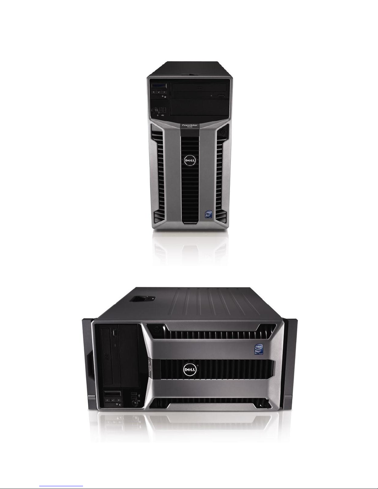
4.3 Front Panel View and Features
Figure 1 and Figure 2 show the front views of the PowerEdge T610.
Figure 1. Front View (Tower Configuration)
Figure 2. Front View (Rack Configuration)
PowerEdge T610 Technical Guide 15
Dell
See the Front-Panel Features and Indicators section in the About Your System chapter of the
PowerEdge T610 Hardware Owner’s Manual on Support.Dell.com for more information.
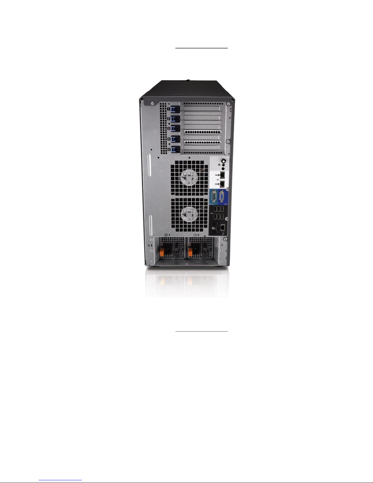
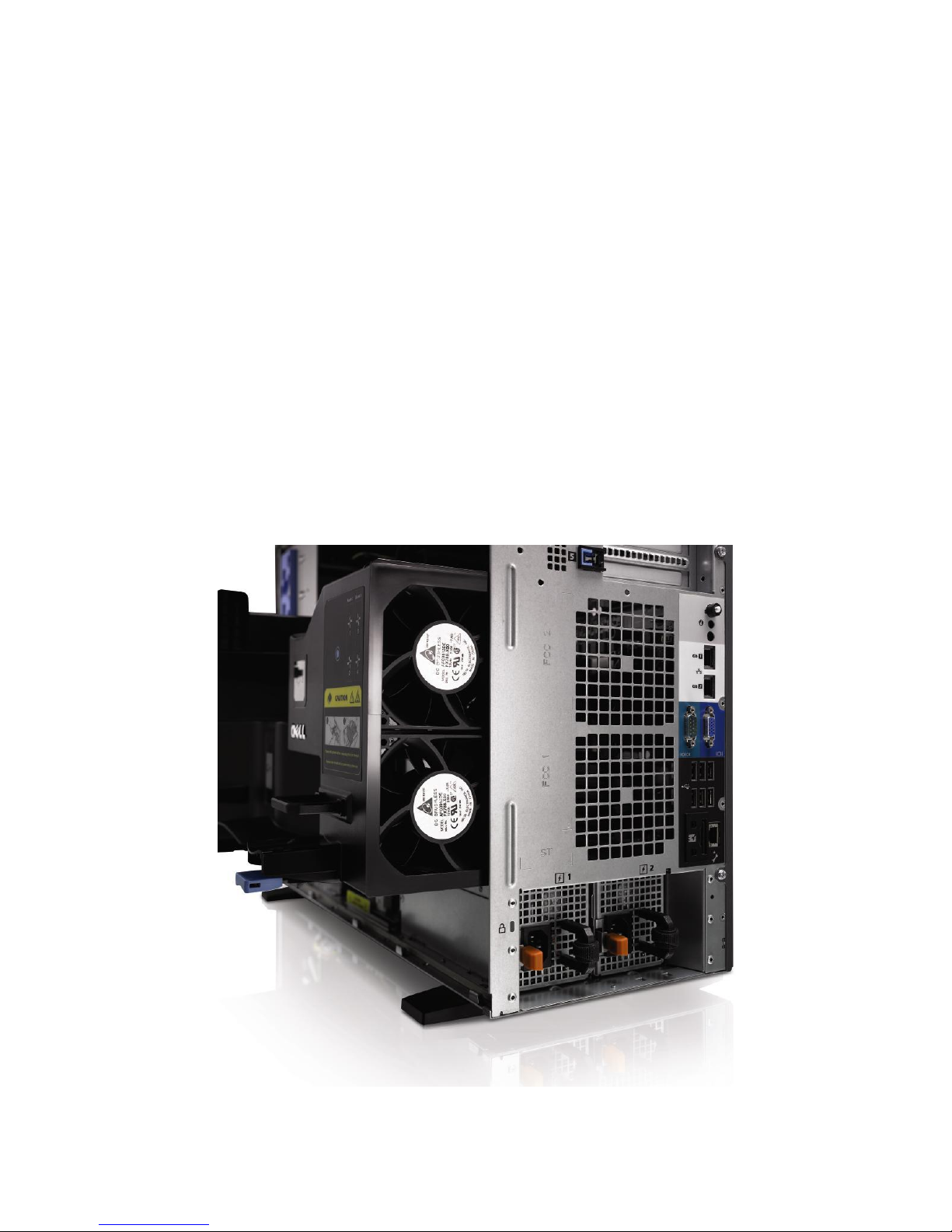
4.4 Back Panel View and Features
Figure 3 shows the back view of the PowerEdge T610.
Figure 3. Back View
See the Back-Panel Features and Indicators section in the About Your System chapter of the
PowerEdge T610 Hardware Owner’s Manual on Support.Dell.com for more information.
4.5 Power Supply Indicators
The PowerEdge T610 redundant power supplies have one status bi-color LED: green for AC power
present and amber for a fault as detailed in Table 4.
PowerEdge T610 Technical Guide 16
Dell
LED
Power Supply Status
AC Power is not present
AC Power is present
Fault of any kind is detected
DC Power is applied to the system
↔
Redundant power supply mismatch
(when hot-plugged/swapped)
Table 4. Power Supply Status
See the Power Indicator Codes section in the About Your System chapter of the PowerEdge T610
Hardware Owner’s Manual on Support.Dell.com for more information.
4.6 NIC Indicators
See the NIC Indicator Codes section in the About Your System chapter of the PowerEdge T610
Hardware Owner’s Manual on Support.Dell.com for more information.
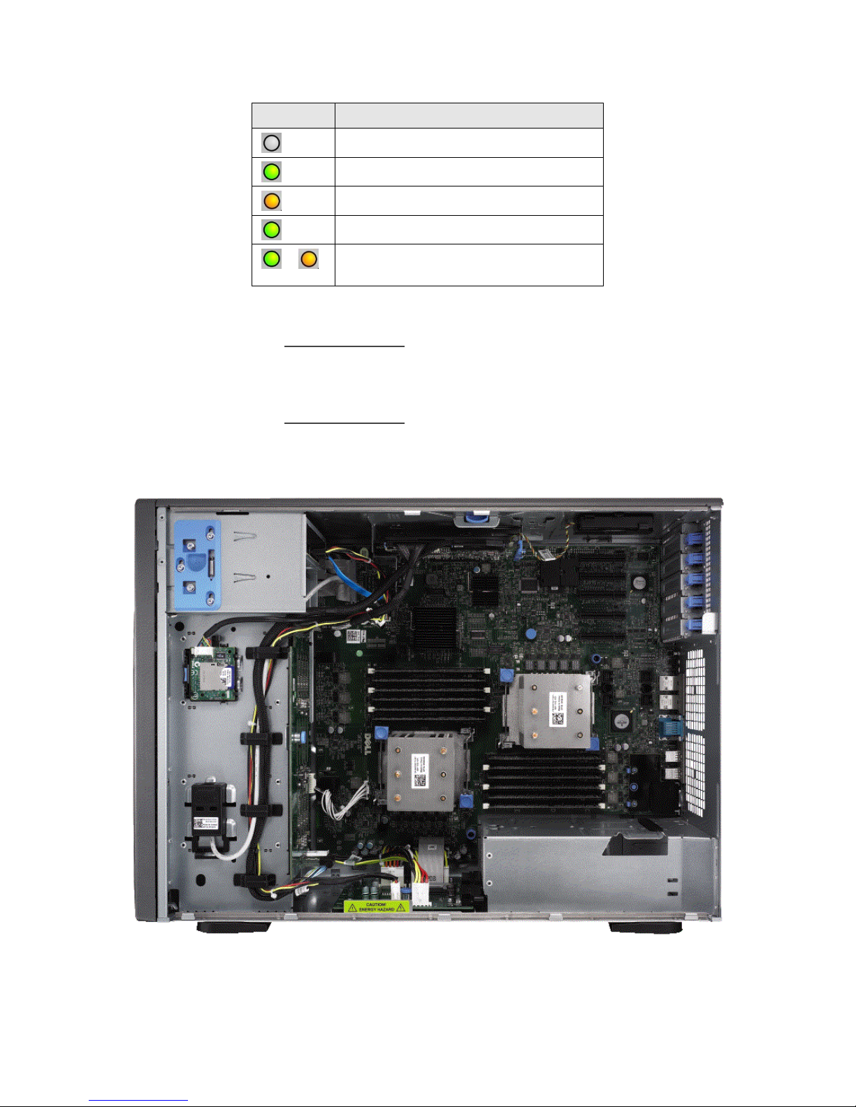
4.7 Internal Chassis Views
Figure 4 shows the internal view of the PowerEdge T610 server.
PowerEdge T610 Technical Guide 17
Figure 4. Internal Chassis View
Dell
4.8 Rails and Cable Management
ReadyRailsTM Sliding Rails for 4-post racks support the following:
Toolless installation in 19‖ EIA-310-E compliant square or unthreaded round hole 4-post racks
including all generations of Dell racks
Tooled installation in 19‖ EIA-310-E compliant threaded hole 4-post racks (requires the 2U
Threaded Rack Adapter Brackets Kit)
Full extension of the system out of the rack to allow serviceability of key internal components
Optional cable management arm (CMA)
See section 14 for more details.
4.9 Fans
Two or four 92 mm single-rotor fans are mounted in the back of the cooling shroud. Each fan has a
single-wire harness that plugs into the planar fan connectors (FAN1 through FAN4). In a nonredundant configuration, two fans must be installed towards the back of the chassis.
The iDRAC6 controls and monitors the speed of the fans. A fan speed fault or over-temperature
condition results in a notification by iDRAC6.
The T610 power supply units have integrated fans. They are cooled by fans in the front section. The
system requires a blank module in place of the empty power supply slot.
All system fans are pulse-width modulated (PWM) fans. Redundant cooling (optional) is supported.
Figure 5. Fans and Cooling Shroud
PowerEdge T610 Technical Guide 18

Dell
4.10 LCD Control Panel
The LCD control panel is located on the front of the system chassis to provide user access to buttons,
display, and I/O interfaces. See Figure 6. The control panel includes the following features:
ACPI-compliant power button with an integrated green power LED (controlled by iDRAC6)
128x20 pixel LCD with controls:
o Two navigation buttons
o Select button
o System ID button
Non-maskable Interrupt (NMI) button (recessed)
Ambient temperature sensor
Figure 6. LCD Control Panel
The LCD panel is a graphics display controlled by the iDRAC6. Both iDRAC6 and BIOS can send error
codes and messages to the display.
The system's LCD panel provides system information and status messages to signify when the system
is operating correctly or when the system needs attention.
BIOS has the ability to enter a secure mode through Setup, which locks the Power and NMI buttons.
When in this mode, the power button can still be used to turn on the server even when the power
button is disabled in System Setup.
For more information on the LCD panel, see the LCD Panel Features section in the About Your System
chapter in the PowerEdge T610 Hardware Owner’s Manual on Support.Dell.com.
4.11 Security
For additional information regarding the following security features, see the PowerEdge T610
Hardware Owner’s Manual on Support.Dell.com.
4.11.1 Cover Latch
The PowerEdge T610 comes with a tooled latch on the side cover of the system that secures it to the
chassis. A locked bezel secures the cover latch.
4.11.2 Bezel
A metal bezel is mounted to the chassis. A lock on the bezel is used to protect un-authorized access
to system hard drives and the control panel. System status on the LCD is viewable even when the
bezel is installed.
The bezel is standard for both the T610 tower and rack systems.
PowerEdge T610 Technical Guide 19

Dell
4.11.3 Hard Drive
The front bezel of the system contains a lock which secures the system hard drives.
4.11.4 TPM
The Trusted Platform Module (TPM) is used to generate and store keys, protect and authenticate
passwords, and create and store digital certificates. The TPM can also be used to store Microsoft®
BitLocker™ keys for hard drive encryption features in Microsoft® Windows Server® 2008. TPM is
enabled through a BIOS option and uses HMAC-SHA1-160 for binding.
4.11.5 Power Off Security
The control panel is designed so the power switch cannot be accidentally activated. The lock on the
bezel secures the switch behind the bezel. In addition, there is a setting in the CMOS setup that
disables the power button function.
4.11.6 Intrusion Alert
A switch mounted on the cooling shroud is used to detect chassis intrusion. When the cover is
opened, the switch circuit closes to indicate intrusion to the iDRAC6. When enabled, the software
can provide notification to the customer that the cover has been opened.
4.11.7 Secure Mode
BIOS has the ability to enter a secure boot mode through Setup. This mode includes the option to
lock out the power and NMI switches on the control panel or set up a system password.
4.12 USB Peripherals
The port on the control panel is for an optional USB key and is located inside the chassis. Some
possible applications of the USB key are listed as follows:
User custom boot and pre-boot OS for ease of deployment or diskless environments
USB license keys for software applications like eToken™ or Sentinel Hardware Keys
Storage of custom logs or scratch pads for portable user defined information (not hot-
swappable)
4.13 Battery
A replaceable coin cell CR2032 3V battery is mounted on the planar to provide backup power for the
Real-Time Clock and CMOS RAM on the ICH chip.
4.14 Field Replaceable Units (FRU)
The planar contains a serial EEPROM to store FRU information including Dell part number, part
revision level, and serial number. The backplane storage enclosure processor (SEP) and the power
supply microcontroller are also used to store FRU data.
4.15 User Accessible Jumpers, Sockets, and Connectors
See the Jumpers and Connectors chapter in the PowerEdge T610 Hardware Owner’s Manual on
Support.Dell.com.
PowerEdge T610 Technical Guide 20
 Loading...