

Page 1
Dell
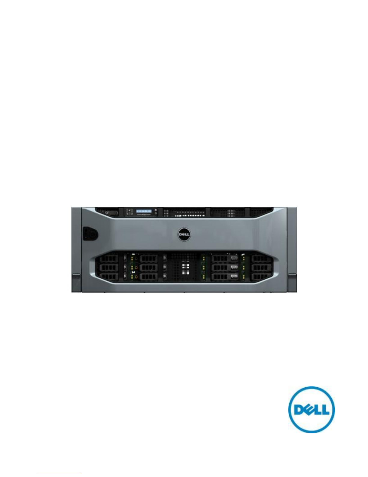
PowerEdge R910
Technical Guide
Page 2

Dell
This document is for informational purposes only. Dell reserves the right to make changes without
further notice to any products herein. The content provided is as is and without express or implied
warranties of any kind.
Dell, PowerEdge, EqualLogic, PowerVault, OpenManage, and ReadyRails are trademarks of Dell, Inc.
Citrix® and XenServer™ are trademarks of Citrix Systems, Inc. and/or one or more of its subsidiaries,
and may be registered in the United States Patent and Trademark Office and in other countries.
Intel, Xeon, and Speedstep are registered trademarks and MMX and Core are trademarks of Intel
Corporation in the U.S. and other countries. HP and COMPAQ are trademarks of Hewlett-Packard
Company. Broadcom is a registered trademark and NetXtreme is a trademark of Broadcom
Corporation and/or its affiliates in the United States, certain other countries and/or the EU.
CommVault Galaxy® or Simpana® are registered trademarks of CommVault Systems, Inc. InfiniBand
is a registered trademark and service mark of the InfiniBand Trade Association. Matrox is a registered
trademark of Matrox Electronic Systems Ltd. Microsoft, Windows, Windows Server, SQL Server, and
BitLocker, and Hyper-V are either registered trademarks or trademarks of Microsoft Corporation in
the United States and/or other countries. Mellanox is a registered trademark of Mellanox
Technologies, Inc. and ConnectX, InfiniBlast, InfiniBridge, InfiniHost, InfiniRISC, InfiniScale, and
InfiniPCI are trademarks of Mellanox Technologies, Inc. Red Hat is a registered trademark of Red Hat,
Inc. in the United States and other countries. Linux is a registered trademark of Linus Torvalds.
Symantec and Backup Exec are trademarks owned by Symantec Corporation or its affiliates in the
U.S. and other countries. QLogic and PathScale are registered trademarks of Qlogic Corporation.
VMware is a registered trademark and vSphere is a trademark of VMware, Inc. in the United States
and/or other jurisdictions. Other trademarks and trade names may be used in this document to refer
to either the entities claiming the marks and names or their products. Dell disclaims proprietary
interest in the marks and names of others.
©Copyright 2010 Dell Inc. All rights reserved. Reproduction or translation of any part of this work
beyond that permitted by U.S. copyright laws without the written permission of Dell Inc. is unlawful
and strictly forbidden.
Revision 1 December 2010
Dell PowerEdge R910 Technical Guide 2
Page 3

Dell
Table of Contents
1 Product Comparison ........................................................................................... 7
1.1 Overview of PowerEdge R910 Benefits ................................................................ 7
1.2 Comparison of PowerEdge R910 to PowerEdge R900 ................................................ 8
2 New Technologies ............................................................................................ 10
2.1 Overview ................................................................................................ 10
2.2 Detailed Information .................................................................................. 10
2.2.1 Intel Xeon Processor 7500 Series ............................................................... 10
2.2.2 Internal Dual SD Module (IDSM) ................................................................ 11
2.2.3 10Gb Embedded NIC ............................................................................. 11
3 System Information .......................................................................................... 12
4 Mechanical .................................................................................................... 15
4.1 Chassis Description..................................................................................... 15
4.2 Dimensions and Weight ................................................................................ 16
4.3 Front Panel View and Features ...................................................................... 17
4.4 Back Panel View and Features ....................................................................... 19
4.5 Power Supply Indicators ............................................................................... 20
4.6 NIC Indicators ........................................................................................... 20
4.7 Internal Chassis View .................................................................................. 21
4.8 Rails and Cable Management ......................................................................... 21
4.9 Fans ...................................................................................................... 21
4.10 Cabling ................................................................................................... 23
4.11 Security .................................................................................................. 24
4.11.1 Cover Latch ....................................................................................... 24
4.11.2 Bezel ............................................................................................... 24
4.11.3 Hard Drive ......................................................................................... 25
4.11.4 Trusted Platform Module (TPM) ................................................................ 25
4.11.5 Power Off Security ............................................................................... 25
4.11.6 Intrusion Alert .................................................................................... 25
4.11.7 Secure Mode ...................................................................................... 25
4.12 USB Key .................................................................................................. 25
4.13 Battery ................................................................................................... 26
4.14 Field Replaceable Units (FRU)........................................................................ 27
4.15 User Accessible Jumpers, Sockets, and Connectors ............................................... 27
5 Electrical ...................................................................................................... 28
5.1 Clock Circuitry .......................................................................................... 28
6 Power, Thermal, Acoustic .................................................................................. 29
6.1 Power Supplies and Power Subsystem .............................................................. 29
6.2 Environmental Specifications......................................................................... 31
6.3 Thermal.................................................................................................. 31
6.4 Acoustics ................................................................................................ 32
7 Processors ..................................................................................................... 35
7.1 Overview ................................................................................................ 35
Dell PowerEdge R910 Technical Guide 3
Page 4

Dell
7.2 Features ................................................................................................. 35
7.3 Supported Processors .................................................................................. 36
7.4 Processor Configurations .............................................................................. 36
7.5 Additional Processor Information .................................................................... 36
8 Memory ........................................................................................................ 37
8.1 Overview ................................................................................................ 37
8.2 Slots/Risers ............................................................................................. 39
8.3 Key Features of the R910 Memory Subsystem ...................................................... 39
8.4 Memory Speed Limitations ............................................................................ 39
8.5 Sparing ................................................................................................... 39
8.6 Mirroring ................................................................................................. 40
8.7 RAID ...................................................................................................... 40
8.8 Supported Configurations ............................................................................. 40
9 Chipset ........................................................................................................ 41
9.1 Intel 7500 Chipset I/O Hub (IOH) .................................................................... 41
9.2 IOH QuickPath Interconnect (QPI) ................................................................... 41
9.3 PCI EXPRESS GENERATION 2 .......................................................................... 41
9.4 Direct Media Interface (DMI) ......................................................................... 41
9.5 Intel I/O Controller Hub 10 (ICH10) ................................................................. 41
9.6 PCI Express Connectors ................................................................................ 42
10 BIOS ............................................................................................................ 43
10.1 Overview ................................................................................................ 43
10.2 System ID ................................................................................................ 43
10.3 I2C ........................................................................................................ 43
11 Embedded NICs/LAN on Motherboard (LOM) ............................................................. 44
12 I/O Slots ....................................................................................................... 45
12.1 Overview ................................................................................................ 45
12.2 Quantities and Priorities .............................................................................. 46
12.3 PCI Card Information .................................................................................. 46
13 Storage ........................................................................................................ 47
13.1 Overview ................................................................................................ 47
13.2 Backplanes .............................................................................................. 47
13.2.1 2.5‖ x4 Backplane ................................................................................ 47
13.2.2 2.5‖ x16 Backplane .............................................................................. 48
13.3 Flash BIOS Memory ..................................................................................... 49
13.4 Drives .................................................................................................... 49
13.5 RAID Configurations .................................................................................... 50
13.6 Storage Controllers .................................................................................... 52
13.6.1 PERC H200 ......................................................................................... 52
13.6.2 PERC H700 ......................................................................................... 52
13.6.3 PERC H800 ......................................................................................... 52
13.6.4 Storage Card Support Matrix .................................................................... 53
13.7 LED Indicators .......................................................................................... 54
13.8 Optical Drives ........................................................................................... 54
14 Video ........................................................................................................... 55
15 Audio ........................................................................................................... 56
16 Rack Information ............................................................................................. 57
Dell PowerEdge R910 Technical Guide 4
Page 5

Dell
16.1 Overview ................................................................................................ 57
16.2 Rails ...................................................................................................... 57
16.3 Cable Management Arm (CMA) ....................................................................... 58
16.4 Rack View ............................................................................................... 58
17 Operating Systems ........................................................................................... 60
18 Virtualization ................................................................................................. 61
19 Systems Management ........................................................................................ 62
19.1 Overview/Description ................................................................................. 62
19.2 Server Management .................................................................................... 62
19.3 Embedded Server Management ...................................................................... 63
19.4 Lifecycle Controller and Unified Server Configurator ............................................ 63
19.5 Optional iDRAC Express ............................................................................... 64
19.6 iDRAC6 Enterprise ...................................................................................... 64
20 Peripherals .................................................................................................... 67
20.1 USB peripherals ......................................................................................... 67
20.2 External Storage ........................................................................................ 67
Tables
Table 1. Product Comparison .................................................................................. 8
Table 2. Summary of R910 features ......................................................................... 12
Table 3. PSU System Configurations ........................................................................ 30
Table 4. Power Supply Specifications ....................................................................... 31
Table 5. Operating/Non-Operating (Storage) Requirements ............................................ 32
Table 6. Acoustics of the PowerEdge R910 ................................................................. 33
Table 7. Configuration Corresponding to Acoustical Data Presented .................................. 34
Table 8. Intel Xeon Processor 7500 Series Cache Sizes ................................................... 35
Table 9. R910 Supported Intel Xeon Processor 7500 Series .............................................. 36
Table 10. R910 Supported HDDs ............................................................................... 49
Table 11. RAID Configurations ................................................................................. 50
Table 12. Storage Card Support Matrix ....................................................................... 53
Table 13. Supported Video Modes ............................................................................ 55
Table 14. Rack Types Supported by the R910 ............................................................... 57
Table 15. Rail Adjustability Range and Depth ............................................................... 58
Table 16. Unified Server Configurator Features and Description......................................... 63
Table 17. Features List for BMC, iDrac, and vFlash ........................................................ 64
Table 18. External Storage ..................................................................................... 67
Table 19. Standards Compliance .............................................................................. 68
Table 20. R910 Volatility ....................................................................................... 70
Figure 1. R910 Front View with Bezel ....................................................................... 15
Figure 2. R910 Front View without Bezel ................................................................... 15
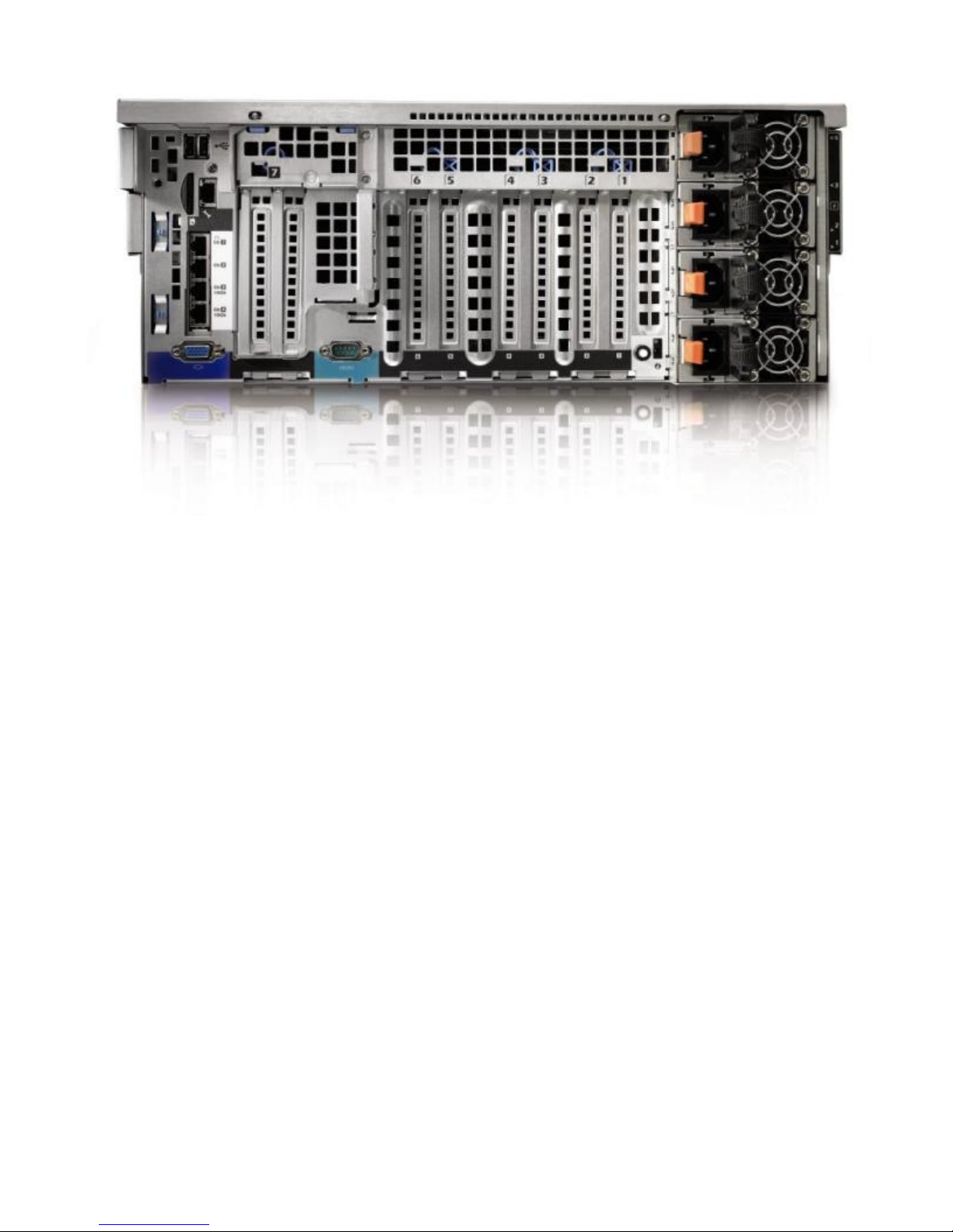
Figure 3. R910 Rear View ...................................................................................... 16
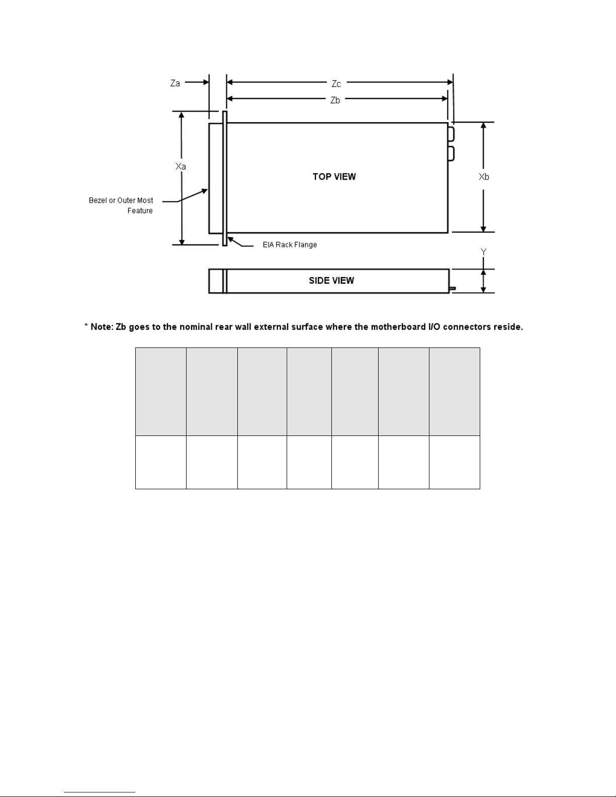
Figure 4. R910 Dimensions .................................................................................... 17
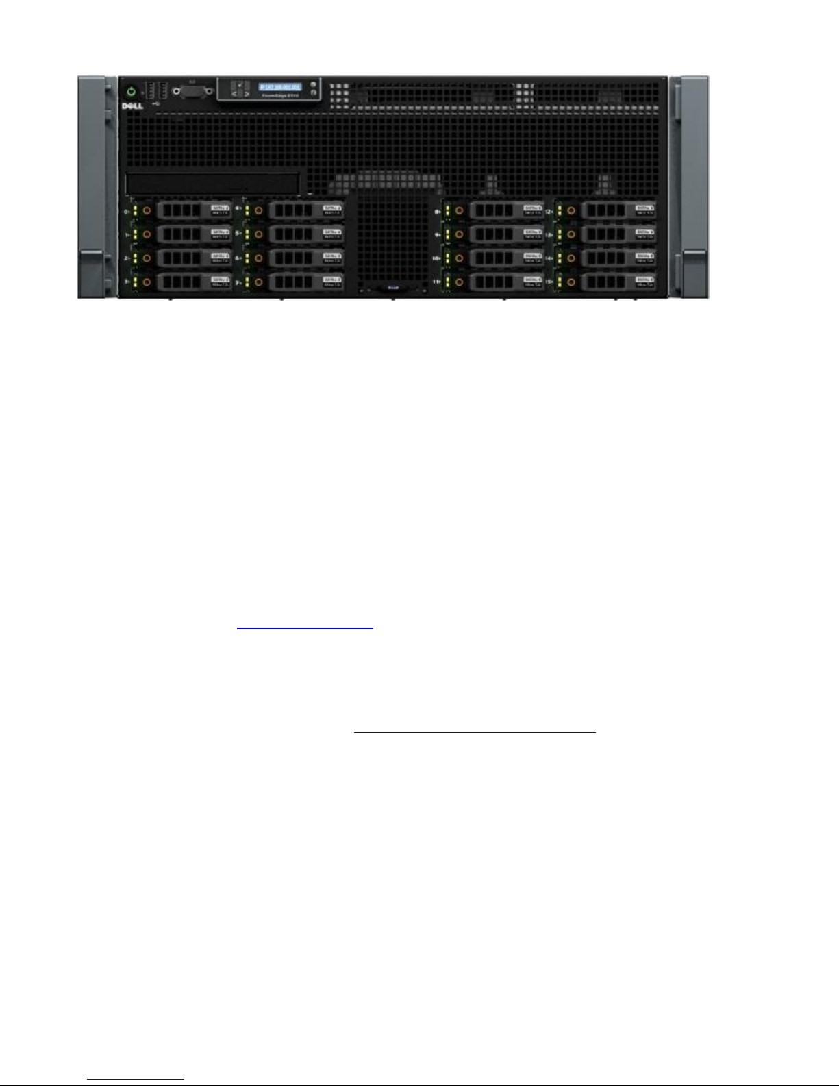
Figure 5. Front Panel View of R910 .......................................................................... 18
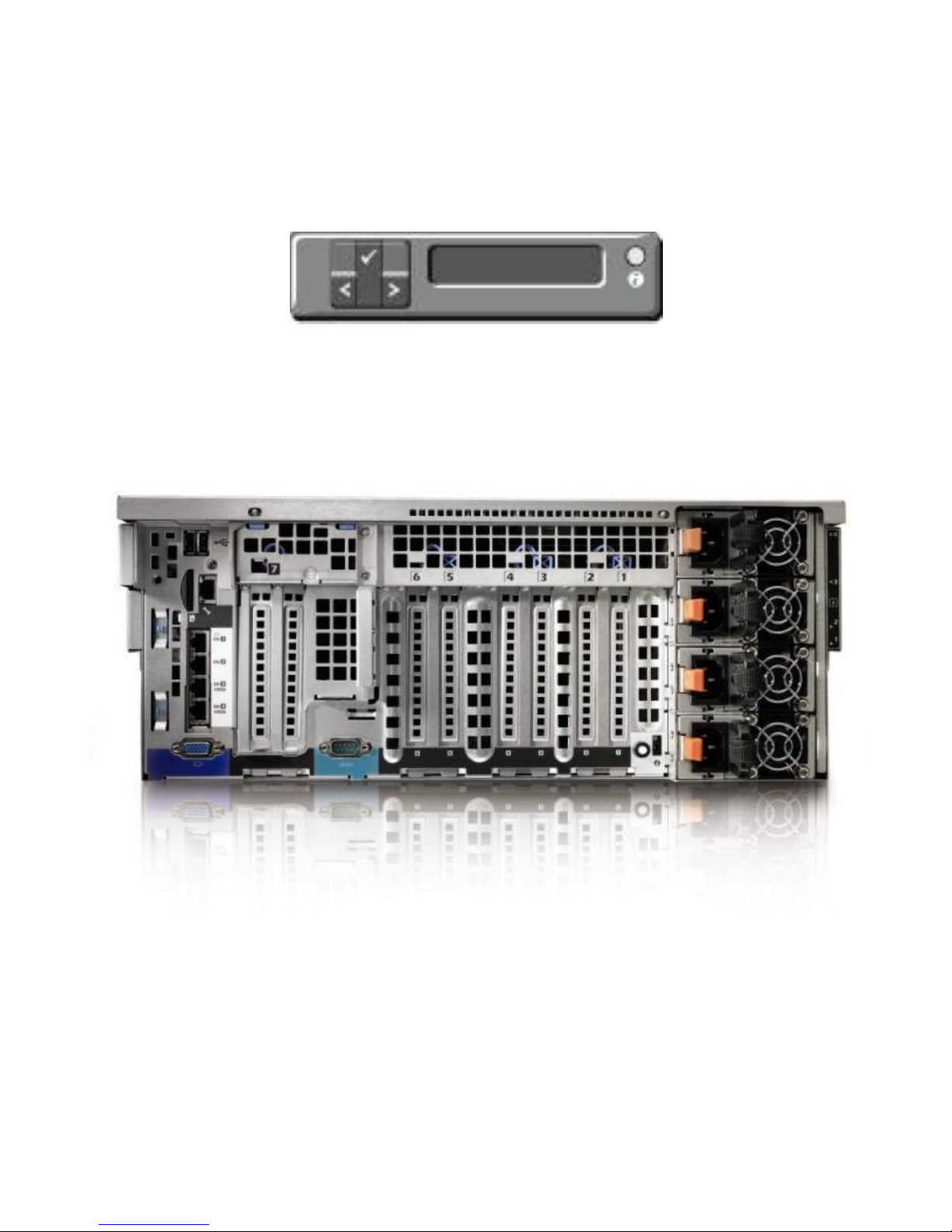
Figure 6. R910 LCD ............................................................................................. 19
Dell PowerEdge R910 Technical Guide 5
Figures
Page 6

Dell
Figure 7. Back Panel View ..................................................................................... 19
Figure 8. Power Supply Indicators ............................................................................ 20
Figure 9. NIC Indicators ........................................................................................ 20
Figure 10. R910 Internal View ............................................................................... 21
Figure 11. R910 Fan Cage .................................................................................... 22
Figure 12. Cabling Diagram .................................................................................. 23
Figure 13. R910 Cover Latch ................................................................................. 24
Figure 14. R910 Bezel Lock .................................................................................. 24
Figure 15. USB Key Location ................................................................................. 26
Figure 16. Coin Cell Battery on Motherboard ............................................................. 27
Figure 17. R910 Power Supply ............................................................................... 29
Figure 18. PowerEdge R910 DIMM Naming and Numbering .............................................. 38
Figure 19. PCIe I/O slots ..................................................................................... 45
Figure 20. 2.5‖ x4 Backplane ................................................................................ 48
Figure 21. 2.5‖ x16 Backplane .............................................................................. 48
Figure 22. 2.5‖ HDD carrier .................................................................................. 49
Figure 23. R910 ReadyRails Sliding Rails with Optional CMA ............................................ 57
Figure 24. R910 Mounted in the B2 Sliding Rails .......................................................... 59
Figure 25. R910 CMA Mounted on the Side Opposite the Power Supplies (Recommended)......... 59
Dell PowerEdge R910 Technical Guide 6
Page 7

1 Product Comparison
1.1 Overview of PowerEdge R910 Benefits
The Dell™ PowerEdge™ R910 provides performance and reliability in a scalable 4U, four-socket server
allowing large workload consolidation or max virtualization machine density.
With Intel® Advanced RAS (Reliability, Availability, Serviceability) Technology, internal dual SD
modules for hypervisor redundancy, including design and component quality paired with Dell
Lifecycle Controller, technicians avoid having to load diagnostics from other media. Dell built-in
reliability saves valuable time and minimizes downtime for mission-critical workloads.
Purpose Built for Reliability
The PowerEdge R910 is built for reliability through factory integration and validation. The Dell ―onetouch‖ process is designed to ensure one person is responsible for the entire server build, resulting in
greater quality control. Every fully configured Dell server is tested (and re-tested) before it leaves
the factory providing customers a fully configured and tested ready-to-deploy server.
Internal Dual SD module provides failover at the hypervisor; this feature was designed based on
customer reliability feedback. Dell listened and delivered.
With Intel Advanced RAS Technology features never before seen in an industry-standard server, the
PowerEdge R910 can automatically monitor, report, and recover from hardware errors to maintain
data integrity and keep mission-critical services online.
Efficient Infrastructure
Performance resources, power efficiency, I/O, and memory scalability are essential to maximizing
workload in the data center.
The PowerEdge R910 delivers the highest performing Xeon 7500 Series processors, up to 1TB of DDR3
memory, and 2 x 10Gb Optional LOM with 10 PCIe slots to help consolidate inefficient workloads.
Energy-efficient system design built with Energy Smart technologies includes power management
features enabling power capping, power inventory, and power budgeting within your specific
environment. Logical component layout of the internal components aids with airflow direction,
helping to keep the server cool.
Intelligent Platforms, Connected Foundations
The PowerEdge R910 follows the 11th Generation PowerEdge behavioral specifications with the same
system design commonality and usability true to the entire portfolio. All 11th Generation servers are
designed to make the user experience easier while saving time and money.
Dell system management solutions focus on simplicity, efficiency, cost containment and reduction,
and an adherence to open standards. Our systems management solutions are complemented by,
connected to, and integrated with 3rd-party offerings, thereby delivering comprehensive solutions
across the complete solutions stack.
The Lifecycle Controller is a chip that is integrated on the server. It helps to simplify administrator
tasks by performing a complete set of provisioning functions such as system deployment, system
updates, hardware configuration, and diagnostics in a pre-OS environment—all from a single,
intuitive interface called the Unified Server Configurator (USC).
The PowerEdge R910 is easy to deploy, better to manage and maintain. Designed to save customers
time and money to focus on what matters most, their people and business.
Page 8

Dell
Feature/Spec
PowerEdge R910
PowerEdge R900 (predecessor)
Processor
Intel® Xeon® Processor 7500 Series
Two or four 4-core, 6-core, or 8-
core
95W, 105W, and 130W TDP options
Intel® Xeon® Processor 7200, 7300, &
7400 Series
Two or four 2-core, 4-core, or 6-core
80W, 90W, and 120W TDP options
Front Side Bus
Up to 6.4 GT/s Quick Path
Interconnect (QPI) links
1066MHz
# Processors
2 or 4
2 or 4
# Cores
4, 6, or 8
2, 4, or 6
L2/L3 Cache
12MB or 18MB or 24MB
8MB or 12MB or 16MB
Chipset
Intel® 7500
Intel® 7300
DIMMs
64 x DDR3
1066 MHz DDR3 RDIMM
32 x FBD
667MHz FBD
Min/Max RAM
4GB/1TB
2GB/256GB
HD Bays
Hot Swap HDD
16 x 2.5‖ HDD
Hot Swap HDD
8 x 2.5‖ HDD
5 x 3.5‖ HDD
HD Types
SAS, SSD
SAS, SATA, Near-line SAS
Ext Drive Bay(s)
External USB floppy & SATA optical
drives
External USB floppy & SATA optical
drives
Int. HD Controller
PERC Η200 or PERC Η700
SAS6iR or PERC6/I
Opt. HD Controller
PERC Η800 or 6Gbps SAS
PERC 6/E or SAS5/E
Availability
Hot Swap HDD
Hot Swap Redundant PSU
Redundant Cooling
ECC memory
Sparing, Mirroring
Single Device Data Correction
(SDDC)
Hot Swap HDD
Hot Swap Redundant PSU
Redundant Cooling
ECC memory
Sparing, Mirroring
Single Device Data Correction (SDDC)
Server Management
OpenManage™ 6.2
OpenManage™ 5.4
I/O Slots
Standard: 7 PCIe Gen2 slots (2 x4, 4
7 PCIe Gen1 (4 x8, 3 x4)
1.2 Comparison of PowerEdge R910 to PowerEdge R900
The Dell™ PowerEdge™ R910 is Dell’s 11th generation general purpose 4-socket 4U Intel® based rack
server. The R910 features the highest level performance scalability, system availability, and I/O
expandability, providing performance and capacity leadership with reliability built-in to run businesscritical applications. R900 is the predecessor of R910.
The PowerEdge R910 and the rest of the 11th generation servers are designed around optimizing
virtualization, system management, usability and industrial design, and best-in-class power and
thermals. The PowerEdge R910 is ideal for large database, virtualization, and business-critical
applications.
Table 1. Product Comparison
Dell PowerEdge R910 Technical Guide 8
Page 9

Dell
Feature/Spec
PowerEdge R910
PowerEdge R900 (predecessor)
x8, 1 x16)
Optional: 10 PCIe Gen2 (6 x4, 4 x8)
Slot5 is Gen1
RAID
PERC H200, PERC H700, PERC H800,
and 6Gbps SAS
PERC 6/I, SAS 6iR and PERC 6/E
NIC/LOM
1GbE or 10Gb embedded NIC
options
4-port (4 x 1GbE) Embedded NIC
Broadcom 5709c
(or)
4-port (2 x 10Gb SFP+ & 2 x 1GbE)
Embedded NIC Broadcom 57711 +
Broadcom 5709c
1GbE embedded NIC
4 port Embedded NIC Broadcom 5708
USB
2 in the rear
2 in the front
1 internal
2 in the rear
2 in the front
1 internal
Power Supplies
Hot swap redundant PSUs
4 x 750W (Energy Smart PSU )
(or)
4 x 1100W (High Output PSU)
Hot swap redundant PSUs
2 x 1570W
Fans
Redundant Cooling
Redundant cooling
Chassis
4U Rack
4U Rack
Chassis depth
~29.6‖
~27.5‖
Dell PowerEdge R910 Technical Guide 9
Page 10

Dell
2 New Technologies
2.1 Overview
The PowerEdge R910 uses a number of new technologies:
Intel 7500 chipset
Intel Xeon processor 7500 series
DDR3 RDIMM memory
Internal Dual SD module
6G SAS technology
10GbE Embedded NIC
2.2 Detailed Information
The Intel Xeon processor 7500 series 4S is the microprocessor designed specifically for server
applications. The processor features 4-core, 6-core, and 8-core processing to maximize performance
and performance/watt for data center infrastructures and highly dense deployments. The Intel Xeon
processor 7500 series 4S also features Intel’s Core™ micro-architecture and Intel 64 architecture for
flexibility in 64-bit and 32-bit applications and operating systems.
2.2.1 Intel Xeon Processor 7500 Series
Key Features of the Intel Xeon processor 7500 series:
Up to eight cores per socket
Up to 24MB shared L3 cache
45nm process technology
Four full-width, bidirectional point-to-point Intel® QuickPath Interconnect (QPI) links at 6.4
GT/s
Four Intel
®
Scalable Memory Interconnects (SMI) at 6.4 GT/s
Socket – LS, LGA 1567 package
No termination required for non-populated CPUs (must populate CPU socket 1 first)
Integrated QuickPath DDR3 memory controller
64-byte cache line size
RISC/CISC hybrid architecture
Compatible with existing x86 code base
Optimized for 32-bit code
MMX support
Execute Disable Bit
Intel
®
Wide Dynamic Execution (Executes up to four instructions per clock cycle)
Simultaneous Multi-Threading (SMT) capability (2 threads/core)
Support for CPU Turbo Mode on certain SKUs (Increases CPU frequency if operating below
thermal, power, and current limits)
Streaming SIMD (Single Instruction, Multiple Data) Extension 4
Intel
Intel
Enhanced Intel
®
64 Technology
®
VT-x and VT-d Technology for virtualization support
®
SpeedStep® Technology
Demand-based switching for active CPU power management as well as support for ACPI P-
States, C-States, and T-States
Dell PowerEdge R910 Technical Guide 10
Page 11

Dell
2.2.2 Internal Dual SD Module (IDSM)
The PowerEdge R910 also offers a second internal USB port dedicated for embedded Hypervisor for
virtualization operating systems like Citrix® and VMware® through a dual SD-to-USB daughter card
called an Internal Dual SD Module. The IDSM port is located on the back of the IO riser board. The SD
Flash Cards contains a bootable OS image for virtualized platforms. IDSM consists of up to two SD
cards that are mirrored when set in the redundant mode for the higher availability.
2.2.3 10Gb Embedded NIC
10Gb I/O cards (Embedded NICs) are designed to provide higher data throughput for demanding
applications like virtualization.
The 10Gb NICs are Broadcom® BCM57711 Gigabit MAC with BCM8727 SFP+ PHY. Features include:
x8 PCI Express Gen2 capable interface
SFP+ interface supported with SR and LRM optics or direct attached cable
TOE (TCP Offload Engine)
iSCSI controller
RDMA controller (RNIC) (enabled through an optional hardware key)
NC-SI (Network Controller-Sideband Interface) connection
Wake-On-LAN (WOL)
PXE 2.0 remote boot
iSCSI boot
IPv4 and IPv6 support
Bare metal deployment support
Dell PowerEdge R910 Technical Guide 11
Page 12
Dell
Feature
Details
Processor
Intel® Xeon® Processor 7500 Series
Two or four 4-core, 6-core, or 8-core
95W, 105W and 130W TDP options
Front Side Bus
Intel® QuickPath Interconnect (QPI) links @ maximum of 6.4 GT/s
# Cores
4, 6, or 8 cores
L2/L3 Cache
12MB, 16MB, 24MB
Chipset
Intel® 7500
Maximum Internal
Storage
Up to 4.8TB
DIMMs/Speed
64 RDIMM DDR3 – 1066 MHz
Memory module capacities of 1GB, 2GB, 4GB, 8GB, or 16GB RDIMMs
Min/Max RAM
4GB/1TBB
HD Bays
Hot-swap HDDs
Up to sixteen 2.5‖ SAS or SSD hard drives
Mixing of SAS and SSD drives
HD Types
SAS and SSD
Ext Drive Bay(s)
External USB floppy
Optional SATA half-height optical drives such as DVD-ROM or DVD+RW
Optional SATA or SCSI half-height (or full-height) tape back-up drive
HD Controller
Internal: PERC Η200 or PERC Η700
Optional: PERC H800 and 6Gbps SAS
BIOS
4MB flash for system BIOS and Video BIOS
Video
Integrated Matrox® G200, 8MB shared video memory
Availability
Hot-swap Hard Drives, Hot-swap Power; Memory SDDC, ECC, Control Line Parity,
Redundant Cooling, Add Interactive LCD with hot-swap HDD chassis
Server Management
Dell™ Embedded Server Management provides IPMI 2.0 compliance.
Remote Management
iDRAC6 Express + Optional iDRAC6 Enterprise
I/O Slots
Standard: 7 PCIe Gen2* slots (2 x4, 4 x8, 1 x16)
Optional: 10 PCIe Gen2* (6 x4, 4 x8)
*Slot5 is Gen1
The storage controller card has a dedicated slot (PCIe x8) apart from the available
10 PCIe slots.
RAID
PERC H200, PERC H700, PERC H800 and 6Gbps SAS
Network Interface
Cards
Embedded NICs:
1GbE or 10Gb embedded NIC options with iSCSI offload
2x Broadcom® 5709c (4 ports x 1GbE Base-T Copper) Embedded NIC or
3 System Information
Table 2. Summary of R910 features
Dell PowerEdge R910 Technical Guide 12
Page 13
Dell
Feature
Details
Broadcom® 57711 (2 ports x 10Gb SFP+) and Broadcom® 5709c (2 ports x 1GbE
Base-T Copper) Embedded NIC
Optional NICs:
Broadcom® 57710 Single Port 10GbE NIC, Copper CAT6 PCIe-8
Intel® DA 10GbE NIC, Dual Port, Optical, PCIe-8
Intel® 10GbE Single Port 10GbE NIC, Copper, PCIe-8
Broadcom® NetXtreme® II 5709 Gigabit NIC w/TOE & iSOE, Quad Port, Copper,
PCIe-4
Broadcom® 5709 Dual Port 1GbE NIC w/TOE PCIe-4, Low Profile
Broadcom® 5709 Dual Port 1GbE NIC w/TOE iSCSI, PCIe-4, Low Profile
Broadcom® 5709 Dual Port 1GbE NIC w/TOE iSCSI, PCIe-4
Broadcom® NetXtreme® II 5709 Gigabit NIC w/TOE & iSOE, Quad Port, Copper,
PCIe-4, Low Profile
Broadcom® 5709 Dual Port 1GbE NIC w/TOE PCIe-4
Broadcom® NetXtreme® II 57711 10GbE NIC w/TOE & iSOE, Dual Port, SFP+, PCIe-8
Intel® Gigabit ET NIC, Dual Port, Copper, PCIe-4, Low Profile
Intel® Gigabit ET Dual Port NIC, PCIe-4
Intel® Gigabit ET NIC, Quad Port, Copper, PCIe-4, Low Profile
Broadcom® 5709 Dual Port 1GbE NIC w/TOE PCIe-4, Low Profile
Intel® Gigabit ET Quad Port NIC, PCIe-4
USB
Total: 5 , USB 2.0 compliant
2 in the rear
2 in the front
1 internal
Power Supplies
Hot-swap redundant PSUs
4 x 750W (Energy Smart PSU )
(or)
4 x 1100W (High Output PSU)
Front Panel
The system control panel is located on the front of the system chassis to provide
user access to buttons, display, and I/O interfaces
LCD on front panel for error messaging
System ID
System ID switch with LED indicator at rear side and LCD indication at front side
128x20 pixel LCD with controls on front panel for system ID and error messaging
System ID for PE R910 is 0x02d3
Fans
Redundant Cooling
Chassis
4U rack-mount
Chassis depth is ~29.6‖
Rack Support
ReadyRails™ sliding rails for tool-less mounting in 4-post racks with square or
unthreaded round holes, with support for optional tool-less cable management arm
Operating Systems
Microsoft® Windows® Essential Business Server 2008
Microsoft® Windows Server® 2008 SP2, x86/x64 (x64 includes Hyper-V™)
Microsoft® Windows Server® 2008 R2, x64 (includes Hyper-V™ v2)
Microsoft® Windows® HPC Server 2008
Dell PowerEdge R910 Technical Guide 13
Page 14

Dell
Feature
Details
Novell® SUSE® Linux® Enterprise Server
Red Hat® Enterprise Linux®
For more information on the specific versions and additions, visit
www.dell.com/OSsupport.
Systems Management
BMC, IPMI 2.0 compliant Dell™ OpenManage™ featuring Dell Management Console,
Unified Server Configurator, Lifecycle Controller enabled via optional iDRAC6
Express, iDRAC6 Enterprise, and vFlash
Dell PowerEdge R910 Technical Guide 14
Page 15
Dell
4 Mechanical
4.1 Chassis Description
The PowerEdge R910 fits in a rack mount 4U chassis. The R910 chassis brings some new features over
previous generations, including:
DIMMs on memory risers
Updated industrial design including a new LCD, bezel, and hard drive carriers
Toolless rack latches
Pull-out tray for Express Service Tag and customer labels
Support for persistent storage (internal USB and SD card slots and external SD card slot)
Updated power supply removal process
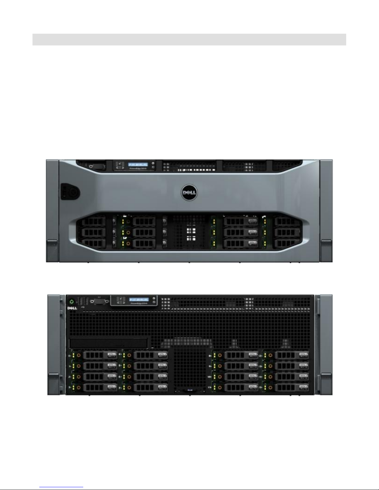
Figure 1. R910 Front View with Bezel
Figure 2. R910 Front View without Bezel
Dell PowerEdge R910 Technical Guide 15
Page 16
Dell
Figure 3. R910 Rear View
4.2 Dimensions and Weight
The R910 weight with maximum configuration is 47.60 kg (105 lb). Weight empty is 26.31 kg (58 lb).
Dell PowerEdge R910 Technical Guide 16
Page 17
Dell
Xa
(Width
w/ Rack
Latches)
Xb
(Width
w/o
Rack
Latches)
Y
(Height)
Za
(Depth
w/
bezel)
Za
(Depth
w/o
bezel)
Zb
(Depth
w/o
power
supply
and
bezel)
Zc
(Depth
w/
power
supply)
48.24
mm
(18.99
in)
42.20
mm
(16.62
in)
17.26
mm (6.8
in)
35.0
mm
20.4
mm
699.0
mm
753.0
mm
Figure 4. R910 Dimensions
4.3 Front Panel View and Features
Dell PowerEdge R910 Technical Guide 17
Page 18
Dell
Figure 5. Front Panel View of R910
The following components and connectors are located on the front of the R910:
Power-on indicator, Power button
USB connectors; connects USB devices to the system; two 4-pin, USB 2.0-compliant
LCD menu buttons which allow you to navigate the control panel LCD menu
LCD panel which provides system ID, status information, and system error messages
Non-Maskable Interrupt (NMI) button
Ambient temperature sensor
System identification button
Optical drive (optional)
Hard drives
The LCD panel is a graphics display controlled by the iDRAC. Error codes can be sent to the display by
either ESM or BIOS. See LCD Panel Features in the Hardware Owner’s Manual for more information.
BIOS will have the ability to enter a ―Secure Mode‖ through Setup, which will lock the Power and NMI
buttons. When in this mode, pressing either button has no effect and does not mask other sources of
NMI and power control.
The system control panel is located on the front of the system chassis to provide user access to
buttons, display, and I/O interfaces. See Front-Panel Features and Indicators in the Hardware
Owner’s Manual.
Features of the system control panel include:
ACPI-compliant power button with an integrated green power LED (controlled by iDRAC6)
128x20 pixel LCD panel with controls
Two navigation buttons
One select button
One system ID button
Non-Maskable Interrupt (NMI) button (recessed)
Ambient temperature sensor
Two external USB 2.0 connectors
Dell PowerEdge R910 Technical Guide 18
Page 19
Dell
The LCD panel is a graphics display controlled by the iDRAC6. Error codes can be sent to the display
by either iDRAC6 or BIOS.
BIOS will have the ability to enter a ―Secure Mode‖ through Setup, which will lock the Power and NMI
buttons. When in this mode, pressing either button has no effect but does not mask other sources of
NMI and power control.
Figure 6. R910 LCD
4.4 Back Panel View and Features
The following components and connectors are located on the rear panel of the R910:
15-pin VGA connector
DB-9 Serial Port connector
(4) RJ-45 Ethernet connectors with 1 GbE IO riser, OR
(2) RJ-45 Ethernet + (2) SFP+ connectors with 10Gb IO riser
Rear System ID button
Rear System Status/ID blue/amber LED
Dell PowerEdge R910 Technical Guide 19
Figure 7. Back Panel View
Page 20
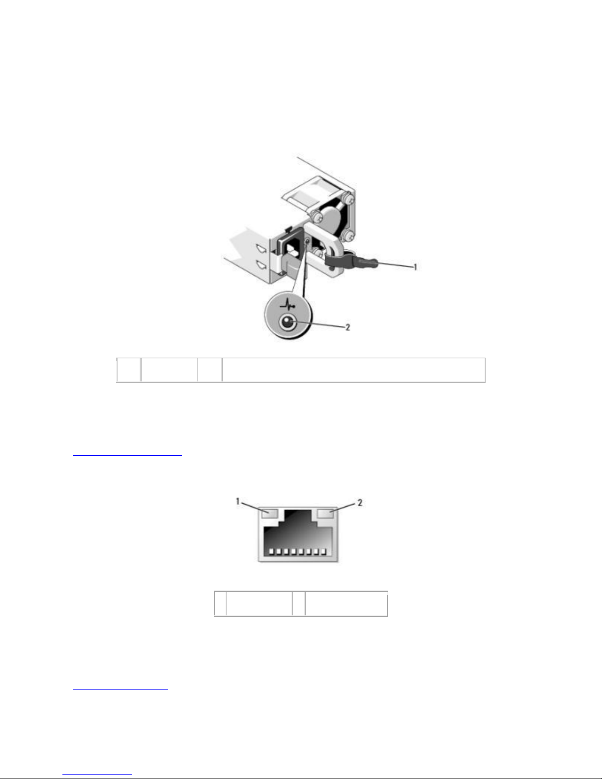
Dell
1
strap
2
power supply status indicator
1
link indicator
2
activity indicator
Active ID Cable Management Arm (CMA) external led jack
(2) USB ports
(Optional) RJ-45 iDRAC6 Enterprise connector
(Optional) vFlash card on the iDRAC6 Enterprise card
4.5 Power Supply Indicators
Figure 8. Power Supply Indicators
See Power Indicator Codes in the Hardware Owner’s Manual for information.
4.6 NIC Indicators
See NIC Indicator Codes in the Hardware Owner’s Manual for information.
Dell PowerEdge R910 Technical Guide 20
Figure 9. NIC Indicators
Page 21
Dell
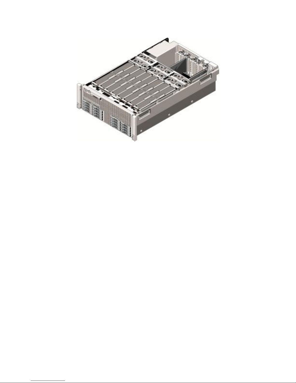
4.7 Internal Chassis View
Figure 10. R910 Internal View
4.8 Rails and Cable Management
ReadyRailsTM Sliding Rails for 4-post racks support the following:
Toolless installation in 19‖ EIA-310-E compliant square or unthreaded round hole 4-post racks
including all generations of Dell racks (Note: Threaded 4-post racks require Dell’s fixed shelf
or 3rd party adapter brackets available through Dell Software & Peripherals.)
Full extension of the system out of the rack to allow serviceability of key internal components
Optional cable management arm (CMA) except on racks less than 1m in depth including Dell
4200 & 2400 racks
Measurements and adjustment ranges for the rack:
Rail depth without the CMA: 755 mm
Rail depth with the CMA: 883 mm
Square-hole rack adjustment range: 686–883 mm
Round-hole rack adjustment range: 672–876 mm
See Section 16 for more information.
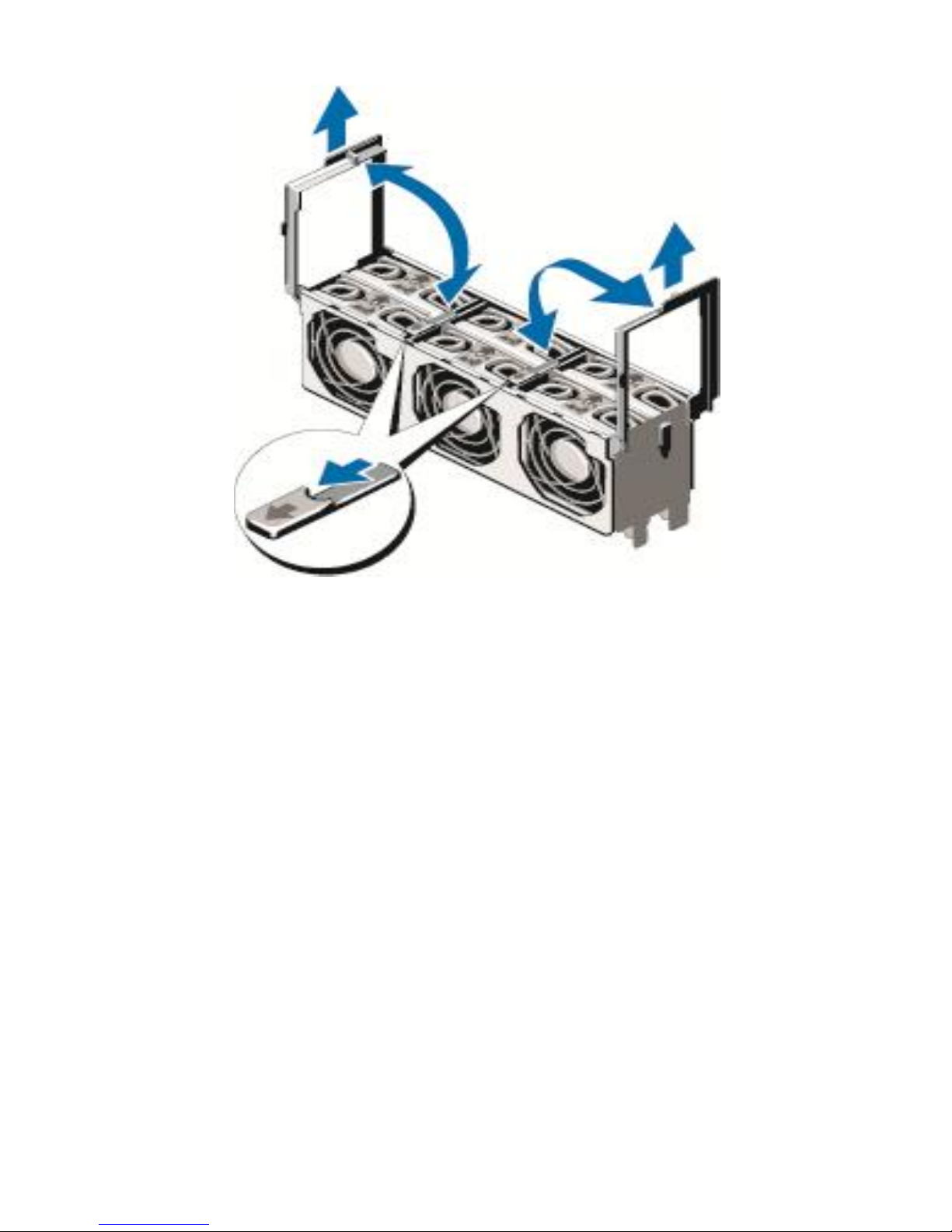
4.9 Fans
Six 120mm single-rotor hot-swappable fans are mounted in a fan bay in the rear of the chassis. Each
fan has a single wire harness that plugs into the planar fan connectors (FAN1 through FAN6).
The Embedded Server Management (ESM) logic in the system controls and monitors the speed of the
fans. A fan speed fault or over-temperature condition results in a notification by ESM.
The R910 Power Supply Units have integrated fans. The system requires a blank in place of the empty
power supply slot. System fan speed is pulse-width modulated.
The iDRAC6 controls and monitors the speed of the fans. A fan speed fault or over-temperature
condition results in a notification by iDRAC6.
Dell PowerEdge R910 Technical Guide 21
Page 22
Dell
Figure 11. R910 Fan Cage
Dell PowerEdge R910 Technical Guide 22
Page 23
Dell
CPU
1
CPU
2
CPU
3
CPU
4
BAT
SLOT1
IOH
1
IOH
2
ICH
10
iDRAC
SLOT2
SLOT3
SLOT4
SLOT5
SLOT6
SLOT7
IO RISER
STORA
GE
SIO
CPLD1
CPLD2
PDB
POWER
Mem Riser 1A
Mem Riser 1B
Mem Riser 3A
Mem Riser 3B
Mem Riser 2A
Mem Riser 2B
Mem Riser 4A
Mem Riser 4B
Cntrl. Panel
BP PWR
SATA
X4
X8
X4
X8
X8
X8
X16
VIDEO
SERIA
L
INT USB
SAS
EXP.
SAS
A
SAS
B
PWR
BACKPLANE
BASEBOARD
SAS CABLE
SATA CABLE
BP PWR
CTRL. PANEL
PDB
CTRL. PANEL
DVDROM
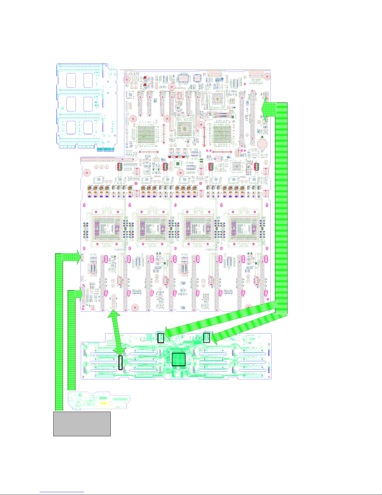
4.10 Cabling
Dell PowerEdge R910 Technical Guide 23
Figure 12. Cabling Diagram
Page 24
Dell
4.11 Security
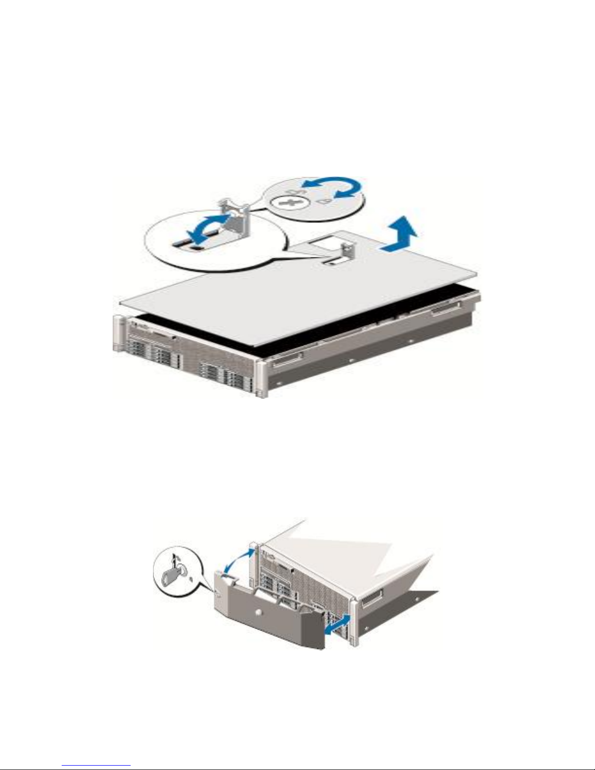
4.11.1 Cover Latch
A tooled latch is integrated in the side cover to secure it to the tower chassis. A locked bezel secures
the cover latch.
Figure 13. R910 Cover Latch
4.11.2 Bezel
A lock on the bezel is used to protect unauthorized access to system hard drives and the system
cover. System status (through the LCD) is viewable when the bezel is installed.
Figure 14. R910 Bezel Lock
Dell PowerEdge R910 Technical Guide 24
Page 25

Dell
4.11.3 Hard Drive
The front bezel of the system contains a lock. A locked bezel secures the system hard drives.
4.11.4 Trusted Platform Module (TPM)
TPM is used to generate/store keys, protect/authenticate passwords, and create/store digital
certificates. TPM can also be used to enable the BitLocker™ hard drive encryption feature in Windows
Server 2008.
TPM is enabled through a BIOS option and uses HMAC-SHA1-160 for binding. A Trusted Computing
Module (TCM) version of the planar is available for use where TCM is the standard, for example, in
China.
4.11.5 Power Off Security
The control panel is designed such that the power switch cannot be accidentally activated. The lock
on the bezel secures the switch behind the bezel. In addition, there is a setting in the CMOS setup
that disables the power button function
4.11.6 Intrusion Alert
A switch mounted on the cooling shroud is used to detect chassis intrusion. When the cover is
opened, the switch circuit closes to indicate intrusion to the iDRAC6. When enabled, the software
can provide notification to the customer that the cover has been opened.
4.11.7 Secure Mode
BIOS has the ability to enter a secure boot mode via Setup. This mode includes the option to lock out
the power and NMI switches on the Control Panel or set up a system password.
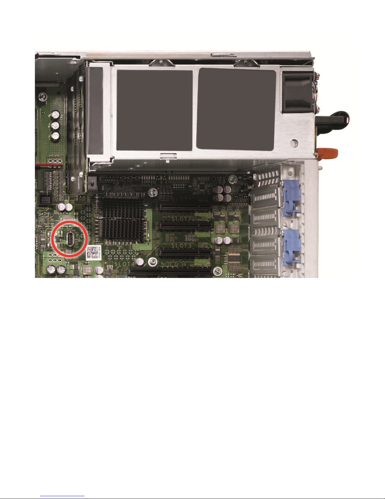
4.12 USB Key
An optional USB memory key installed inside your system can be used as a boot device, security key,
or mass storage device. The USB connector must be enabled by the Internal USB Port option in the
Integrated Devices screen of the System Setup program.
To boot from the USB memory key, configure the USB memory key with a boot image and then
specify the USB memory key in the boot sequence in the System Setup program.
See Figure 15 below.
Dell PowerEdge R910 Technical Guide 25
Page 26
Dell
Figure 15. USB Key Location
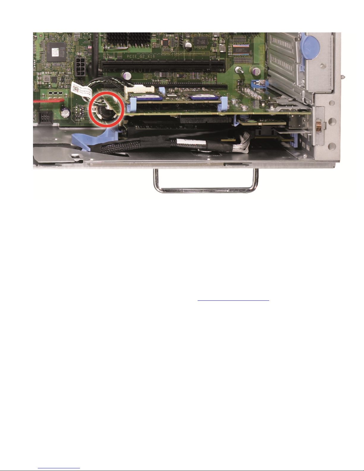
4.13 Battery
A replaceable coin cell CR2032 3V battery is mounted on the planar to provide backup power for the
Real-Time Clock and CMOS RAM on the ICH10 chip. See Figure 16 below.
Dell PowerEdge R910 Technical Guide 26
Page 27
Dell
Figure 16. Coin Cell Battery on Motherboard
4.14 Field Replaceable Units (FRU)
The planar contains a serial EEPROM to store FRU information including Dell part number, part
revision level, and serial number. The backplane SEP and the power supply microcontroller are also
used to store FRU data.
4.15 User Accessible Jumpers, Sockets, and Connectors
For information on jumpers and connector settings, see Jumpers and Connectors in the Hardware
Owner’s Manual.
Dell PowerEdge R910 Technical Guide 27
Page 28

Dell
5 Electrical
5.1 Clock Circuitry
System clock circuitry is based on Intel CK410B+ synthesizer and DB1200/DB800 driver
specification. A clock synthesizer device is a single chip solution. The CK410B+ synthesizes
and distributes a multitude of clock outputs at various frequencies, timings and drive levels
using a single 14.318 MHz crystal.
PCI Express Gen2 support
Host clock support (133 MHz)
Spread spectrum support
33 MHz, 48 MHz, 100 MHz clock support
14.318 MHz clock support
Dell PowerEdge R910 Technical Guide 28
Page 29
Dell
6 Power, Thermal, Acoustic
The PowerEdge R910 achieves enhanced power efficiency by implementing the following features:
User-selectable power cap (subsystems will throttle to maintain the specified power cap)
Improved power budgeting
Larger heat-sinks for processors and IOH
Accurate inlet temperature
PSU/VR efficiency improvements
Switching regulators instead of linear regulators
Closed loop thermal throttling
Increased rear venting/3D venting
PWM fans with an increased number of fan zones and configuration-dependent fan speeds
Use of DDR3 memory (lower voltage than DDR2)
CPU VR dynamic phase shedding
Memory VR static phase shedding
Random time interval for system start
Allows an entire rack to power on without exceeding the available power
BIOS Power/Performance options page
BIOS-based CPU P-state manager (power management in a virtualized environment)
Ability to slow down or throttle memory
Ability to disable a CPU core
Ability to turn off items not being used (i.e., USB ports, embedded NICs, unused PCIe lanes,
etc.)
Option to run PCIe at Gen1 speeds instead of Gen2
6.1 Power Supplies and Power Subsystem
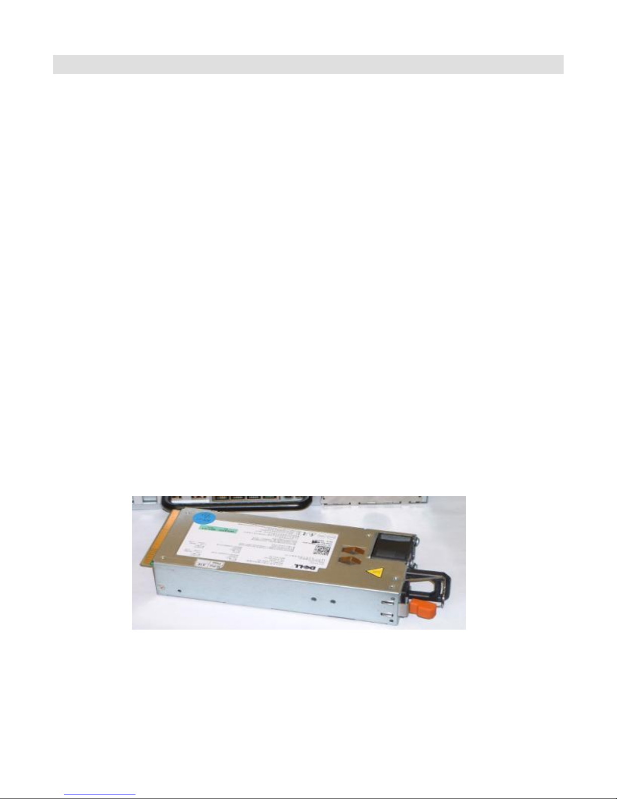
PowerEdge R910 supports two types of power supply units (PSUs):
1100W High Output PSU
750W EnergySmart PSU
Figure 17. R910 Power Supply
Dell PowerEdge R910 Technical Guide 29
Page 30

Dell
High Output Power Supply (1100W), Non-Redundant configuration (1+0)
High Output Power Supply (1100W), Redundant Energy Optimal configuration (1+1)
High Output Power Supply (1100W), Non-Redundant Full-power configuration (2+0)
High Output Power Supply (1100W), Fail-over configuration (2+1)
High Output Power Supply (1100W), Redundant Full-power configuration (2+2)
Energy Smart Power Supply (750W), Non-Redundant configuration (1+0)
Energy Smart Power Supply (750W), Redundant Energy Optimal configuration (1+1)
Energy Smart Power Supply (750W), Non-Redundant Full-power configuration (2+0)
Energy Smart Power Supply (750W), Fail-over configuration (2+1)
Energy Smart Power Supply (750W), Redundant Full-power configuration (2+2)
The power supply bay is designed to prevent unsupported power supplies from being installed. Mixing
of 1100W and 750W power supplies is not supported. R910 power supplies have embedded cooling
fans and one bi-colored status LED.
The PowerEdge R910 PSUs have a FRU EEPROM; FRU data is stored in the memory of the PSU
Microcontroller. PSU Firmware can be updated by iDRAC over the PMBus. Power is “soft-switched,”
allowing power cycling via a switch on the front of the system enclosure or through a software control
(through server management functions). The power system is compatible with industry standards, such
as ACPI and the Microsoft Windows Server Hardware Design Guide.
If not using all 4 power supplies, it is preferred that the power supply be installed starting from PS1 bay
in order to avoid power loss in the PDB Copper planes. However, there is nothing that prevents the use
of the rest of the bays in that case. The empty bays should be populated with the PS sheet metal
blanks for thermal reasons.
The power supplies connect indirectly to the planar via the Power Distribution Board (PDB). There is
a power cable that connects between the PDB and the backplane. Another cable also connects the
PDB to the optical and/or tape drives.
R910 has 4 power supply bays. PSU system configurations are shown in Table 3.
Table 3. PSU System Configurations
There are two different redundancy modes with 2 PSUs present in the system. One is (2+0) nonredundant capable of running full system configuration, and the other is (1+1) redundant running
limited configuration. The user could switch the mode between (1+1) and (2+0) via iDRAC GUI only
for the two PS case depending on if the system is capable of supporting the new mode or not. The
other modes of redundancy are automatics based on the functional supplies present at the time
when AC is applied and system is powered ON. See Power Supplies in the Hardware Owner’s Manual
for more information.
In the (2+2) mode, if the power supplies are evenly split across two separate grids on the AC line
side, then this mode would also be considered ―AC or Grid‖ redundant in addition to power.
The system power distribution consists of one, two, three or four AC-to-DC power supplies connected
to the planar through the PDB. The power supply only provides +12V and +12Vaux. The power
supplies connect directly to the planar via the Power Distribution Board (PDB). There are no cables
involved for delivering the power from the PSUs to the motherboard.
The 12V power is then distributed to the rest of the subsystems like the backplane and optical drive
from the motherboard using cables. There are several voltage regulators in the system to supply
different voltage levels needed by different logic devices.
Dell PowerEdge R910 Technical Guide 30
Page 31

Dell
AC Power supply (per power supply)
Wattage
1100 W (High Output PSU)
750 W (Energy Smart PSU)
Voltage
90–264 V, 47–63 Hz, auto-ranging
Heat dissipation
8407 BTU/hr maximum (with two or four
1100 W PSUs)
5732 BTU/hr maximum (with two or four
750W PSUs)
Maximum inrush current
Under typical line conditions and over the
entire system ambient operating range, the
inrush current may reach 55 A per power
supply for 10 ms or less
Table 4. Power Supply Specifications
6.2 Environmental Specifications
Airborne Contaminant Level: Class G2 or lower as defined by ISA-S71.04-1985
For additional information about environmental measurements for specific system configurations, see
Product Safety, EMC, and Environmental Datasheets on Dell.com.
6.3 Thermal
The R910 thermal solution includes:
Optimized airflow impedance for optimum cooling efficiency
Custom air baffling directs airflow through the components to maintain proper cooling
Custom designed heat sinks maintain CPU, IOH, and Mill Brook chip temperatures within
thermal design targets
Highly Optimized Fan Control Algorithm
o Base fan speeds are a function of hardware configuration and ambient temperature to
minimize airflow for a given environment.
o PID control algorithms are used for both CPU and DIMMs to maintain appropriate
thermal margin
o Double refresh switching allows for DIMM temperature excursions up to 95°C while
maintaining performance and thermal design targets
The R910 thermal algorithm monitors the thermal sensor on each DIMM to maintain
DIMM temperatures below the typical 85°C specification in normal operating
conditions.
Under extreme operating conditions the thermal algorithm can switch the DIMMs
into Double Refresh mode allowing an additional 10°C of thermal headroom. In
Double Refresh mode DIMMs are allowed to operate as high as 95°C.
Dell PowerEdge R910 Technical Guide 31
Page 32
Dell
Temperature
Operating
10o to 35 o C (50 o to 95 o F) with a maximum temperature gradation of 10o C per
hour. Note: For altitudes above 2950 feet, the maximum operating temperature is
derated 1o F/550 feet.
Storage
–40 o to 65 o C (-40 o to 149 o F) with a maximum temperature gradation of 20o C per
hour
Relative Humidity
Operating
20% to 80% (noncondensing) with a maximum humidity gradation of 10% per hour
Storage
5% to 95% (noncondensing) with a maximum humidity gradation of 10% per hour
Maximum Vibration
Operating
0.26 Grms at 5-350 Hz in operational orientations
Storage
1.54 Grms at 10-250 Hz in all orientations
Maximum Shock
Operating
Half sine shock in all operational orientations of 31G +/- 5% with a pulse duration of
2.6 ms +/- 10%
Storage
Half sine shock on all six sides of 71G +/- 5% with a pulse duration of 2 ms +/-10%;
Square wave shock on all six sides of 27 G with velocity change @ 235 in/sec or
greater
Altitude
Operating
-16 to 3048 m (-50 to 10,000 ft) Note: For altitudes above 2950 feet, the maximum
operating temperature is derated 1oF/550 feet
Storage
-16 to 10,600 m (-50 to 35,000 ft)
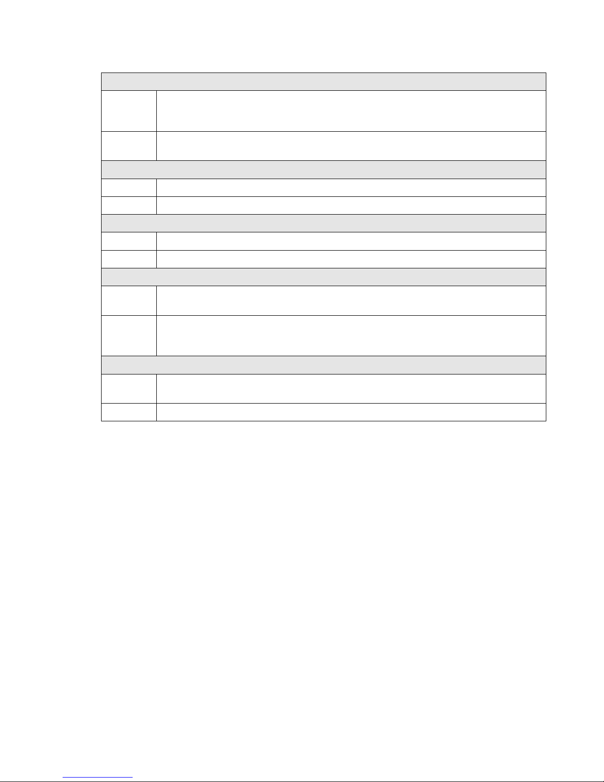
Table 5. Operating/Non-Operating (Storage) Requirements
6.4 Acoustics
The acoustical design of the PowerEdge R910 reflects the following:
Adherence to Dell’s high sound quality standards. Sound quality is different from sound
power level and sound pressure level in that it describes how humans respond to annoyances
in sound, like whistles, hums, etc. One of the sound quality metrics in the Dell specification
is prominence ratio of a tone, and this is listed in the table below.
Noise ramp and descent at bootup. Fan speeds, hence noise levels, ramp during the boot
process in order to add a layer of protection for component cooling in the case that the
system were not to boot properly.
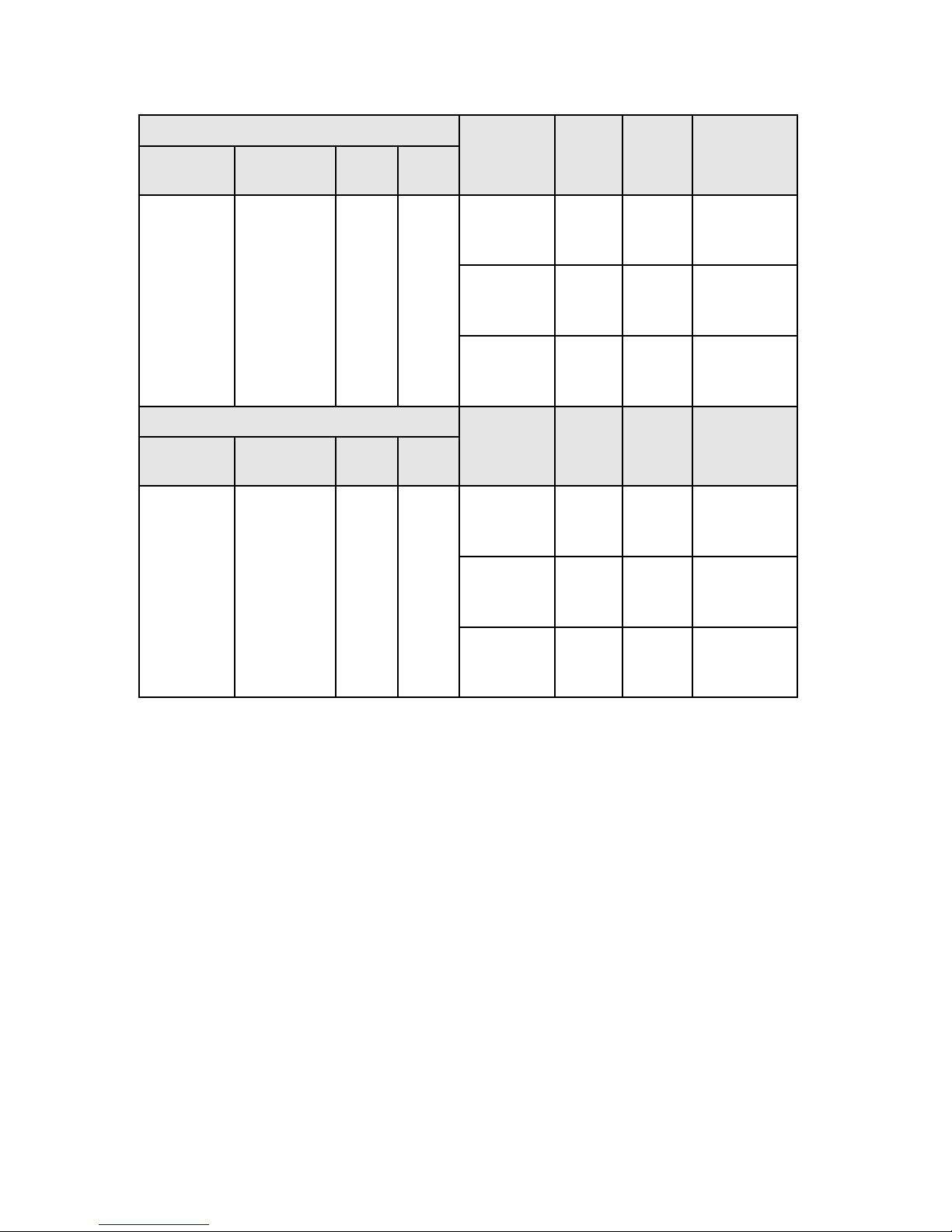
Noise levels vs. configurations. Hardware configurations do result in different noise levels.
For example, processor-power dependence is shown in the following table.
Dell PowerEdge R910 Technical Guide 32
Page 33
Dell
Typical Configuration(1) @ 23 ± 2 °C
Operating
Mode
LWAUL(2)
(Bels)
LpA(3)
(dBA)
TONES(4)
CPU
HDD
RAID
DIMM
4 x Intel
105W
procs
4 x 146GB
SAS 15
krpm)
PERC
H800
16 x
2GB
DIMM
Standby
3.2
16
No
prominent
tones
Idle
5.7
38
No
prominent
tones
Stress
5.6
38
No
prominent
tones
Higher End Configuration @ 23 ± 2 °C
Operating
Mode
LWAUL(2)
(Bels)
LpA(3)
(dBA)
TONES
CPU
HDD
RAID
DIMM
4 x Intel
130W
procs
4 x 600GB
SAS (2.5‖/
15k RPM)
PERC
H800
16 x
8GB
DIMM
Standby
3.2
16
No
prominent
tones
Idle
6.4
45
No
prominent
tones
Stress
6.4
45
No
prominent
tones
Table 6. Acoustics of the PowerEdge R910
(1) Typical configuration means the system is populated with projected average quantity, type,
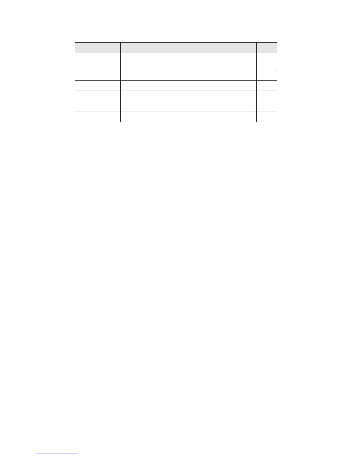
capacity, speed, etc., of components, as shown in the table below
(2) LwA – UL is the upper limit sound power level (LwA) calculated per section 4.4.2 of ISO 9296
(1988) and measured in accordance to ISO 7779 (1999).
(3) LpA is the average bystander A-Weighted sound pressure level. The system is placed in a rack
with its bottom at 25 cm from the floor, and four acoustical transducers are at bystander
positions, ref ISO7779 (1999) Section 8.6.2.
(4) Prominent tone: Criteria of D.5 and D.8 of ECMA-74 9th ed. (2005) are followed to determine if
discrete tones are prominent. The system is placed in a rack with its bottom at 75 cm from the
floor. The acoustical transducer is at front bystander position, ref ISO7779 (1999) Section 8.6.2.
Dell PowerEdge R910 Technical Guide 33
Page 34
Dell
Component
Description
Qty
Processor
Highest attach-rate range bin Intel® E7540 (105W) 4 Memory
2 GB(1066)
16
Power supply
Redundant, 1100-W
4
Hard Drives
146 GB SAS, 15 krpm
4
PCI Cards
PERC H800
1
ODD
DVD-ROM
1
Table 7. Configuration Corresponding to Acoustical Data Presented
Dell PowerEdge R910 Technical Guide 34
Page 35

Dell
Cache
Size
L1 cache size
32 KB instruction
32 KB data
L2 cache size
1.0MB, 1.5MB or 2MB
L3 cache size
12MB, 18MB or 24 MB
(shared)
7 Processors
7.1 Overview
The Intel Xeon processor 7500 series is designed specifically for high-end server applications. The
processor features up to eight-core processing to maximize performance and performance/watt for
data center infrastructures and highly dense deployments. The Intel Xeon processor 7500 series also
features Intel® Core™ micro-architecture and Intel 64 architecture for flexibility in 64-bit and 32-bit
applications and operating systems.
The Intel Xeon processor 7500 series uses a 1567-contact Flip-Chip Land Grid Array (FC-LGA) package
that plugs into a surface-mount socket (Socket-LS). The PowerEdge R910 provides support for up to
four processors.
Selective Intel Xeon processor 7500 series 4S SKUs also support Turbo Mode. Turbo Mode is an OScontrolled operation that automatically allows the processor to run faster than the marked frequency
if the CPU is operating below power, temperature, and current limits.
Table 8. Intel Xeon Processor 7500 Series Cache Sizes
7.2 Features
Key features of the Intel 7500 processor series include:
Up to eight cores per processor
Four point-to-point QuickPath Interconnect links at 6.4 GT/s
1567-pin FC-LGA(Flip Chip-Land Grid Array) package
45 nm process technology
No termination required for non-populated CPUs (must populate CPU socket 1 first)
Two Integrated DDR3 memory controllers
Each Memory controller supports two Intel Scalable Memory Interconnects (SMI) for a total of
4 SMIs
64-byte cache line size
RISC/CISC hybrid architecture
Compatible with existing x86 code base
MMX™ support
Execute Disable Bit
Intel Wide Dynamic Execution
Executes up to four instructions per clock cycle
Simultaneous Multi-Threading (SMT) capability
Support for CPU Turbo Mode (on certain SKUs)
Increases CPU frequency if operating below thermal, power and current limits
Streaming SIMD (Single Instruction, Multiple Data) Extensions 2, 3, and 4
Dell PowerEdge R910 Technical Guide 35
Page 36

Dell
Model
Speed
TDP Power
Cache
Cores
QPI Speed
X7560
2.26GHz
130W
24M
8
6.4GT/s
X7550
2.00GHz
130W
18M
8
6.4GT/s
E7540
2.00GHz
105W
18M
6
6.4GT/s
L7555
1.86GHz
95W
24M
8
5.86GT/s
L7545
1.86GHz
95W
18M
6
5.86GT/s
E7530
1.86GHz
105W
12M
6
5.86GT/s
E7520
1.86GHz
105W
18M
4
4.8GT/s
Intel 64 Technology
Intel VT-x and VT-d Technology for virtualization support
Enhanced Intel SpeedStep
®
Technology
Demand-based switching for active CPU power management as well as support for ACPI P-
States, C-States and T-States
7.3 Supported Processors
Table 9. R910 Supported Intel Xeon Processor 7500 Series
7.4 Processor Configurations
The system is designed such that at least both CPU1 & CPU2 processors are required to access all the
I/O expansion slots. There are two IOH QPI-to-PCIe bridges in order to provide sufficient PCIe lanes
to meet the MRD requirements. IOH1 is the legacy bridge that is connected to CPU1 and where as
IOH2 is connected to CPU2. If only CPU1 is populated, the I/Os behind IOH2 (slots 1, 2, 3, 4 and 6)
will not be available.
The system will not boot up if the CPUs are not installed correctly. The supported CPU configuration
is either 2-processors or 4-processors.
7.5 Additional Processor Information
Refer to the Hardware Owner’s Manual for additional processor information.
Dell PowerEdge R910 Technical Guide 36
Page 37

Dell
8 Memory
8.1 Overview
The PowerEdge R910 uses DDR3 memory providing a high-performance, high-speed memory interface
capable of low latency response and high throughput. The R910 supports Registered ECC DDR3 DIMMs
(RDIMM).
R910 uses Intel 7500 series CPUs that have two integrated memory controllers. Each of those memory
controllers then has two Scalable Memory Interconnect (SMI) channels that connect to the memory
buffer. The R910 has both the SMI channels from each controller routed to the memory riser with two
memory buffers connected.
The SMI channels from each controller operate in lockstep i.e. the DIMMs need to be populated in
matched pairs behind lockstep channel. Each Millbrook buffer has two DDR3 channels that can
support up to two DIMMs per channel.
The DDR3 memory interface consists of 16 Mill Brook buffers, each of which has two DDR3 memory
channels. Each channel supports up to two RDIMMs for single/dual/quad rank. By limiting to two
DIMMs per DDR channel, the system can support DIMMs at 1067 MHz.
The R910 memory interface supports memory demand and patrol scrubbing, single-bit correction and
multi-bit error detection. Correction of a x4 or x8 device failure (―chip kill‖) is supported with SDDC.
The following properties/rules apply to R910:
• DIMMs must be populated in matched pairs for each CPU (A1/A2, A3/A4…). Single DIMM
operation is not supported.
• If DIMMs of different speeds are mixed, all channels will operate at the fastest common
frequency. (Note that R910 only supports DDR3 1067 modules)
• Memory Mirroring and Sparing configurations will be supported as follows:
• Memory sparing will be allowed on configurations with >= 64GB populated
• Memory Mirroring will be enabled on configurations with >=64GB populated
• The first DIMM slot in each channel is color-coded with white ejection tabs for ease of
installation.
• In the case of mixed-rank population, populate the DIMM with the highest number of ranks
first (in sockets with white ejection tabs)
• DIMM sockets are placed 0.450‖ (11.43 mm) apart, center-to-center in order to provide
enough space for sufficient airflow to cool stacked DIMMs. DIMMs must be installed in each
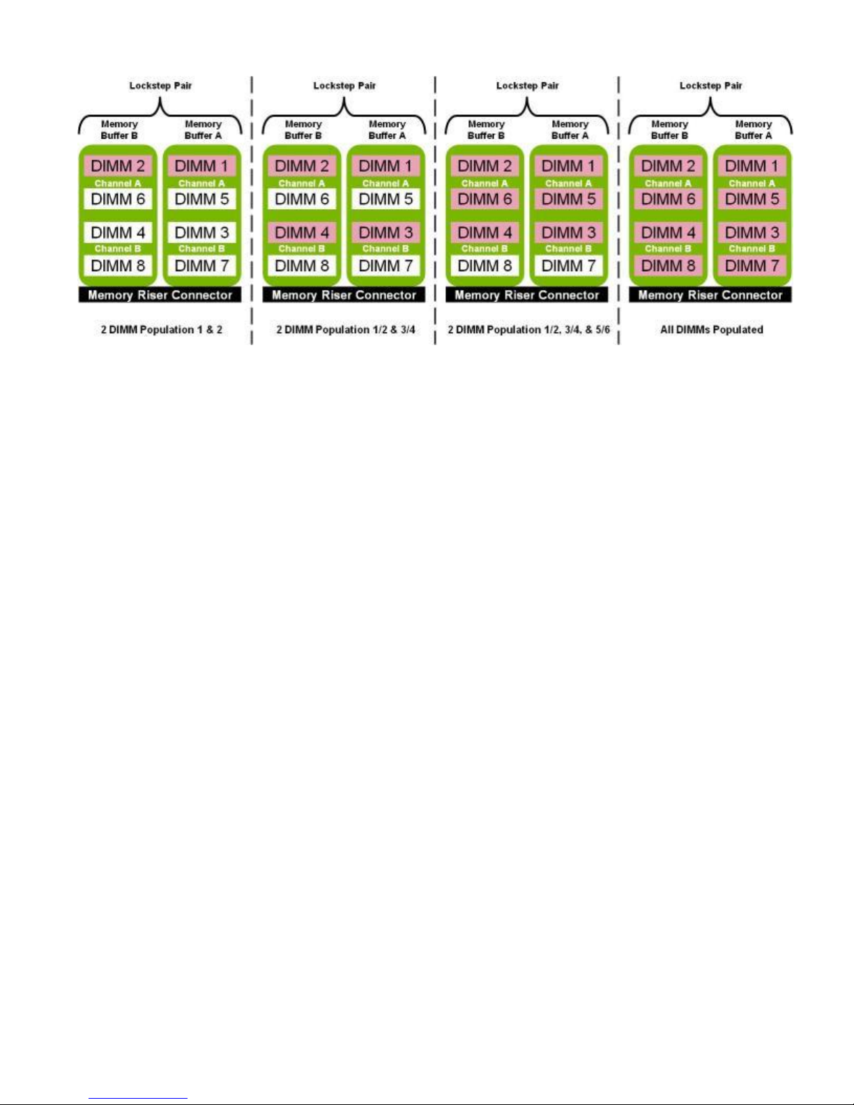
channel starting with the DIMM farthest from the processor (DIMM 1). Population order is
identified by silkscreen and a label. The order is dependent on the memory configuration
used. See Figure 18 for DIMM naming and population ordering.
Dell PowerEdge R910 Technical Guide 37
Page 38
Dell
Figure 18. PowerEdge R910 DIMM Naming and Numbering
Dell PowerEdge R910 Technical Guide 38
Page 39

Dell
8.2 Slots/Risers
R910 has 8 memory risers; each memory riser has 8 DIMM slots. So there are a total of 64 DIMMs. See
System Memory in the Hardware Owner’s Manual for detailed information.
8.3 Key Features of the R910 Memory Subsystem
Registered (RDIMM) ECC DDR3 technology
Each channel carries 64 data and 8 ECC bits
Support for up to 1TB of memory (with 64 16GB RDIMMs)
Support for 1066 MHz single, dual, and quad rank DIMMs
Support ODT (On Die Termination)
Clock gating (CKE) to conserve power when DIMMs are not accessed
o DIMMs enter a low power self-refresh mode
2
I
C access to SPD EEPROM for access to RDIMM thermal sensors
Single-Bit Error Correction
SDDC (Single Device Data Correction — x4 or x8 devices)
Support for Closed Loop Thermal Management on RDIMMs
Multi-Bit Error Detection
Support for Memory Mirroring in limited configurations
Support for Memory (Rank) Sparing in limited configurations
8.4 Memory Speed Limitations
The memory frequency is determined by a variety of inputs:
Speed of the DIMMs
Speed supported by the CPU (note the DDR3 speed is 1/6 the frequency of the SMI link)
BIOS can limit frequency to DDR3 800 based on user power savings configuration in the SETUP
menu
The PowerEdge R910 supports DDR3 1067 DIMMs. Some CPU SKU’s will have lower SMI link speeds
resulting in slower DDR3 buses. The supported frequencies are as follows:
SMI link speed at 4.8GT/sec => DDR3 800
SMI link speed of 5.86 GT/sec => DDR3 978
SMI link speed of 6.4 GT/sec => DDR3 1067
8.5 Sparing
For Rank sparing, one rank on each lockstep Mill Brook pair will be reserved as a spare, and in the
event that another rank exceeds a threshold of correctable ECC errors, the ―failing‖ rank will be
copied to the spare. Once that operation is complete, the failed rank will be disabled.
Dell PowerEdge R910 Technical Guide 39
Page 40

Dell
8.6 Mirroring
For mirroring, the PowerEdge R910 supports 2P/4P configurations for 64GB and larger only. When
mirroring is enabled, only half of the physical memory is visible to the system software. A full copy
of the memory is maintained, and in the event of an uncorrectable error, the system will switch over
to the mirrored copy. The R910 uses intra-socket mirroring.
8.7 RAID
The PowerEdge R910 does not support memory RAID.
8.8 Supported Configurations
See System Memory in the Hardware Owner’s Manual for detailed information.
Dell PowerEdge R910 Technical Guide 40
Page 41

Dell
9 Chipset
The R910 system-board incorporates the Intel 7500 chipset (Boxboro‐EX) for I/O and processor
interfacing. The Intel 7500 chipset is designed to support Intel’s 6500 and 7500 4S processor family,
QPI interconnect, DDR3 memory technology, and PCI Express Generation 2. The Intel 7500 chipset
consists of the EX IOH, Intel® 7500 Scalable Memory Buffer, and the ICH10 South Bridge.
9.1 Intel 7500 Chipset I/O Hub (IOH)
The R910 motherboard incorporates dual Intel 7500 chipset IOH to provide a link between the Intel
Xeon 6500 and 7500 series 4S processors and the I/O components. The main components of the IOH
consist of two full-width QPI links (one to each processor), 72 lanes of PCIe Gen2, and a x4 DMI link
to connect directly to the ICH10 South Bridge.
9.2 IOH QuickPath Interconnect (QPI)
The QuickPath Architecture consists of serial point-to-point interconnects for the processors and the
IOH. The PowerEdge R910 has a total of four QuickPath Interconnect (QPI) links including one link
connecting the processors and links connecting both processors with the IOH and links connecting
both IOHs. Each link consists of 20 lanes (full-width) in each direction with a link speed of 6.4 GT/s.
An additional lane is reserved for a forwarded clock. Data is sent over the QPI links as packets.
The QuickPath Architecture features four layers. The Physical layer consists of the actual connection
between components. It supports Polarity Inversion and Lane Reversal for optimizing component
placement and routing. The Link layer is responsible for flow control and the reliable transmission of
data. The Routing layer is responsible for the routing of QPI data packets. Finally, the Protocol layer
is responsible for high-level protocol communications, including the implementation of a MESIF
(Modify, Exclusive, Shared, Invalid, Forward) cache coherence protocol.
9.3 PCI EXPRESS GENERATION 2
PCI Express is a serial point to point interconnects for I/O devices. PCIe Gen2 doubles the signaling
bit rate of each lane from 2.5 Gb/s to 5 Gb/s. Each of the PCIe Gen2 ports is backwards compatible
with Gen1 transfer rates.
9.4 Direct Media Interface (DMI)
The DMI (previously called the Enterprise Southbridge Interface) connects the Boxboro‐EX Legacy IOH
with the Intel I/O Controller Hub (ICH). The DMI is equivalent to a x4 PCIe Gen1 link with a transfer
rate of 1 GB/s in each direction.
9.5 Intel I/O Controller Hub 10 (ICH10)
ICH10 is a highly integrated I/O controller, supporting the following functions:
• Six x1 PCIe Gen1 ports, with the capability of combining ports 1-4 as a x4 link
• These ports are used on PowerEdge R910 for slot 5
• PCI Bus 32-bit Interface Rev 2.3 running at 33 MHz
• Up to six Serial ATA (SATA) ports with transfer rates up to 300 MB/s
• R910 features one SATA port for optional internal optical drive
• Six UHCI and two EHCI (High-Speed 2.0) USB host controllers, with up to twelve USB ports
(R910 has four external USB ports and one internal ports dedicated for IDSM and embedded
storage)
• Power management interface (ACPI 3.0b compliant)
Dell PowerEdge R910 Technical Guide 41
Page 42

Dell
• Platform Environmental Control Interface (PECI)
• Intel Dynamic Power Mode Manager
• I/O interrupt controller
• SMBus 2.0 controller
• Low Pin Count (LPC) interface to Super I/O, Trusted Platform Module (TPM), and SuperVU
• Serial Peripheral Interface (SPI) support for up to two devices (R910 BIOS flash device is
connected to the ICH10 using SPI)
9.6 PCI Express Connectors
The R910 planar incorporates four 164-pin PCI Express-style x8 (slots 1, 2, 3 and 5) and three
164-pin PCI Express-style x16 connectors (slots 4, 6 and 7) for connectivity to the PCIe cards.
Only one x16 (slot 7) out of the three physical connectors is electrically x16 as well. The other
two (slots 4 & 6) are electrically x8 using a x16 physical connector for double wide GPGPU
adapters.
Dell PowerEdge R910 Technical Guide 42
Page 43

Dell
10 BIOS
10.1 Overview
The R910 BIOS is based on the Dell BIOS core, and supports the following features:
Intel Xeon Processor 7500 Series Support
Simultaneous Multi-Threading (SMT) support
CPU Turbo Mode support
PCI 2.3 compliant
Plug n’ Play 1.0a compliant
MP (Multiprocessor) 1.4 compliant
Boot from hard drive, optical drive, iSCSI drive, USB key, and SD card
ACPI support
Direct Media Interface (DMI) support
PXE and WOL support for on-board NICs
Memory mirroring and spare bank support
SETUP access through <F2> key at end of POST
USB 2.0 (USB boot code is 1.1 compliant)
F1/F2 error logging in CMOS
Virtual KVM, CD, and floppy support
Unified Server Configurator (UEFI 2.1) support
Power management support including DBS, Power Inventory and multiple Power Profiles
10.2 System ID
The System ID for the PowerEdge R910 is 0x02d3.
10.3 I2C
I2C is a simple bi-directional 2-wire bus for efficient inter-integrated circuit control. All I2C-bus
compatible devices incorporate an on-chip interface which allows them to communicate directly with
each other via the I2C-bus. These I2C devices perform communication functions between intelligent
control devices (e.g., microcontrollers), general-purpose circuits (e.g., LCD drivers, remote I/O
ports, memories) and application-oriented circuits.
The PE R910, BIOS accesses the I2C through the ICH10 (Intel I/O Controller Hub 10). There are two
MUXes on ICH10’s I2C bus.
One MUX (U_ICH_SPD) controls the DIMM SPDs through four split segments
The other MUX (U_ICH_MAIN) controls the clock buffers, TOE, USB Hub through four split
segments.
BIOS controls both the MUXes through the two select lines using GPIO pins.
Clock chip, USB hub, and the front panel EEPROM device addresses are located on the IOH I2C bus.
Dell PowerEdge R910 Technical Guide 43
Page 44

Dell
11 Embedded NICs/LAN on Motherboard (LOM)
R910 supports two options for Embedded NICs (I/O riser card):
• 4-port 1GbE using 2x Broadcom 5709c
• 4-port (2 x 10Gb SFP+ & 2 x 1GbE) using 1 x Broadcom 57711 & 1 x Broadcom 5709c
iSCSI offload is standard on both options.
Option 1: 1GbE I/O riser
Two dual-port Broadcom BCM5709C Gigabit Ethernet controllers with support circuitry are embedded
on the R910 1GbE IO riser board. Features of the LAN device include:
• x4 PCI Express Gen2 capable interface
o R910 operates dual-port controllers at Gen1 speed
• MAC and PHY integrated
• 3072x18 Byte context memory
• 64 KB receive buffer
• TOE (TCP Offload Engine)
• iSCSI controller
• RDMA controller (RNIC) (enabled through an optional hardware key)
• NC-SI (Network Controller-Sideband Interface) connection
• Wake-On-LAN (WOL)
• PXE 2.0 remote boot
• iSCSI boot
• IPv4 and IPv6 support
• Bare metal deployment support
Option 2: 10Gb I/O riser
In addition to a Broadcom BCM5709C dual port Ethernet controller, there is a dual-port 10 Gb MAC
controller along with the external PHY embedded on the R910 10 Gb IO riser board. The devices are
Broadcom BCM57711 Gigabit MAC with BCM8727 SFP+ PHY. Features include:
x8 PCI Express Gen2 capable interface
SFP+ interface supported with SR and LRM optics or direct attached cable
TOE (TCP Offload Engine)
iSCSI controller
RDMA controller (RNIC) (enabled through an optional hardware key)
NC-SI (Network Controller-Sideband Interface) connection
Wake-On-LAN (WOL)
PXE 2.0 remote boot
iSCSI boot
IPv4 and IPv6 support
Bare metal deployment support
NOTE: Four functional PSUs (2+2 config) are required in order to use the 10Gb I/O riser.
Dell PowerEdge R910 Technical Guide 44
Page 45
Dell
12 I/O Slots
12.1 Overview
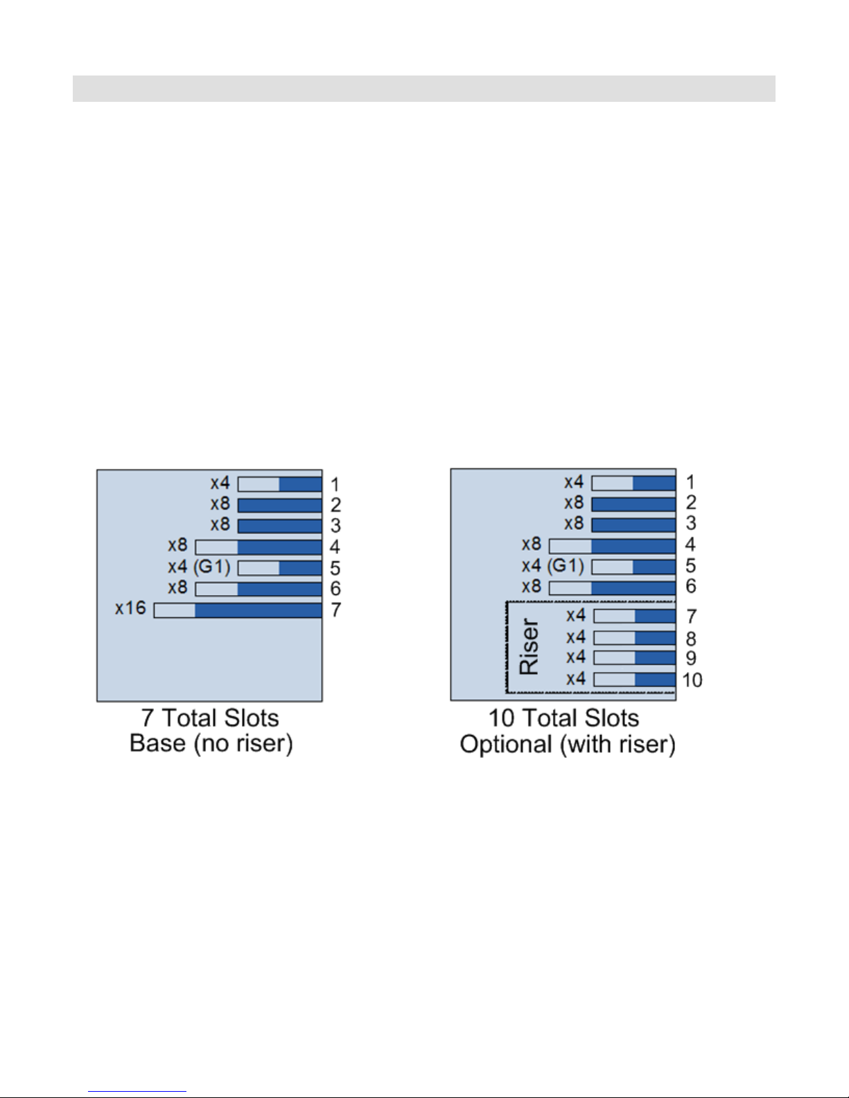
The R910 planar provides seven PCI Express expansion slots as the base. There is an option to expand
the x16 Slot7 with a PCIe riser to four x4 additional slots, bringing the total number of open
expansion slots to ten with the riser option. There is also a dedicated storage slot.
One x4 PCIe Gen2 slot full height with x8 physical connector (Slot 1)
One x4 PCIe Gen1 slot full height with x8 physical connector (Slot 5)
Two x8 PCIe Gen2 slots full height with x8 physical connector (Slots 2 & 3)
Two x8 PCIe Gen2 slots full height with x16 physical connector (Slots 4 & 6)
One x16 PCIe Gen 2 slot full height with x24 physical connector (Slot 7)
Four x4 PCIe Gen 2 slots half height with x8 physical connector on optional riser (Slots 7-
10)
One x8 PCIe Gen2 slot for dedicated storage controller card—connected to the IOH
System supports 25 W maximum power capability for each expansion slot
R910 does not support hot-swapping of PCIe cards
R910 does not support full length PCIe cards
Dell PowerEdge R910 Technical Guide 45
Figure 19. PCIe I/O slots
Page 46

Dell
12.2 Quantities and Priorities
See Expansion Cards and Expansion Card Riser in the Hardware Owner’s Manual for information on
PCI slot priorities and installation order.
12.3 PCI Card Information
PCI card dimensions and limitations are as follows:
Standard height (4.376‖)
The R910 does not support full-length cards (Half length cards are 6.6’, Full length cards
are 12.283‖)
No support for hot-swap or hot-removal
Compliant with the PCI Express Card Electromechanical Specification Rev 2.0
The PowerEdge R910 supports x16 cards that meet the following requirements:
Standard height (4.376”)
Half length (6.6”)
Support for full bandwidth of x16 Gen2 link
No support for hot-swap or hot-removal
Maximum power of 25W
R910 provides +12V, +3.3V, and +3.3Vaux in accordance with Power Supply Rail
Requirements.
x16 slot is not compliant with the PCI Express x16 Graphics 150W-ATX Specification
x16 cards must be compliant with the PCI Express Card Electromechanical Specification
Rev 2.0
x16 cards could occupy the space of two slots (dual wide)
x16 card is limited to 25W initial start-up power until it is configured as a high power device.
If no value is set for the Slot Power Limit, the card is limited to 25W. The card must then
either scale down to 25W or disable operation per PCI Express Base Spec Rev 2.0
x16 card must be able to support a maximum operating temperature of 55°C as defined in
the Dell PCI Environmental Spec and the PCI Express Card Electromechanical Spec (See
Product Safety, EMC and Environmental Datasheets on Dell.com). The R910 provides a
minimum transverse air velocity of “x” LFM (linear feet per minute) to the x16 card.
For more information, please refer to the following specifications:
PCI Express Base Specification, Rev 2.0, 12/20/06
PCI Express Card Electromechanical Specification, Rev 2.0, 4/11/07
PCI Express x16 Graphics 150W-ATX Specification, Rev 1.0, 10/25/04
PCI Environmental Specification, Rev A00, 2/14/05
Dell PowerEdge R910 Technical Guide 46
Page 47

Dell
13 Storage
13.1 Overview
The R910 system supports up to sixteen 2.5” hard disk drives.
Support for 10,000 and 15,000 rpm 2.5” SAS drives
Support for SATA 2.5” solid state drives (SATA SSD)
Support for 7,200 rpm 2.5” Enterprise SATA drives (only 1 SATA HDD supported)
Hard drives must use the 2.5” drive carrier
Mixing of SAS and SATA 2.5” drives in the same system is not supported
Mixing of SAS and SSD drives in the same system is supported
13.2 Backplanes
R910 supports either a (1) sixteen drive backplane or a (2) four drive backplane for 2.5” drives.
Depending on the type of backplane, there are sixteen or four hot-swap capable Serial Attached SCSI
(SAS) or Serial ATA (SATA) drive slots with two LED indicators per slot, up to two Mini-SAS cable
connectors for connecting the backplane to the integrated PERC H200 or H700 storage adapters, and
a 20-pin planar signal/power connector. PERC H200 storage adapter will only be supported with the
2.5” 4-drive HDD backplane.
13.2.1 2.5” x4 Backplane
The 4-drive 2.5‖ HDD backplane assembly is as follows:
Only 2.5” HDD are supported in this configuration
One Mini-SAS cable is used to connect channel “A” of the integrated PERC H200 or H700
storage controller card to the four-drive backplane.
Mixing SATA and SAS is NOT supported.
Dell PowerEdge R910 Technical Guide 47
Page 48
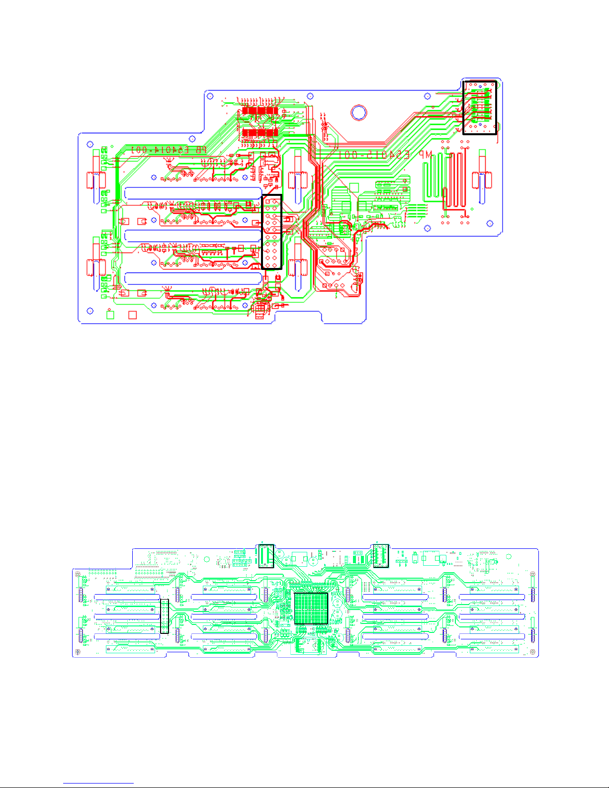
Dell
POWER
SAS A
6 Gb SAS
EXPANDER
SAS A
SAS B
POWER
Figure 20. 2.5” x4 Backplane
13.2.2 2.5” x16 Backplane
The 16-drives 2.5‖ HDD backplane assembly is as follows:
Only 2.5” HDD are supported in this configuration
Two Mini-SAS cables are used to connect both channels of the integrated PERC H700
storage card to the sixteen-drive backplane.
A SAS expander is used to map 16 HDD to the PERC H700 (2 x4 SAS) controller
Mixing SATA and SAS is NOT supported.
Mixing SAS and SSD is supported.
Dell PowerEdge R910 Technical Guide 48
Figure 21. 2.5” x16 Backplane
Page 49
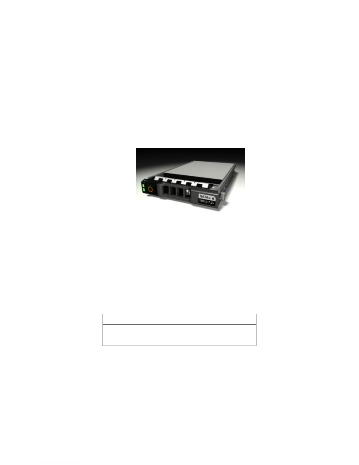
Dell
SAS HDD (2.5‖)
146GB, 300GB
SATA HDD (2.5‖)
160GB
SATA SSD (2.5‖)
50GB, 100GB
13.3 Flash BIOS Memory
A Flash EEPROM resides on the SPI Bus for BIOS and configuration storage. A 16 Mbit device is utilized
for this function. The Flash memory permits the BIOS to be upgraded in the field. The Flash BIOS may
be write-protected by software
13.4 Drives
The PowerEdge R910 supports the new 2.5‖ hard drive carriers. These carriers implement new
industrial design to match the front bezel.
For the slots that are not occupied by drives, a carrier blank is provided to maintain proper cooling,
maintain a uniform appearance to the unit, and provide EMI shielding.
R910 supports diskless configuration.
Figure 22. 2.5” HDD carrier
Each hard drive carrier has two LED indicators visible from the front of the system. One is a green
LED for disk activity and the other is a bicolor (Green/Amber) LED for status information. The
activity LED is driven by the disk drive during normal operation. The bicolor LED is controlled by the
SEP device on the backplane. Both LEDs are used to indicate certain conditions under direction of a
storage controller.
Table 10. R910 Supported HDDs
Dell PowerEdge R910 Technical Guide 49
Page 50

Dell
Configuration
Type
Configs
Description
Non Mixed drives (all SATA HDD, all SAS
HDD, or all SATA SSD or all SAS SSD)
2.5” Drives
x4 Backplane
x16 Backplane
Min
Drives
Max
Drives
Config
Type
Max
Drives
Diskless
Configuration
C0
NCZ
Diskless Configuration
0 0 X
X
SAS HDD/SATA
HDD/SATA
SSD/SAS SSD –
No RAID
C1
MSS
Integrated SAS HDD/SATA HDD/
SSD No RAID (PERC H200, PERC
H700)
1 4 X
X
SAS HDD/SATA
HDD/SATA
SSD/SAS SSD –
RAID
C2
MSSRO
Integrated SAS HDD / SSD RAID 0
(PERC H200, PERC H700)
2 4 2
16
C3
MSSR1
Integrated SAS HDD/ SSD RAID 1
(PERC H200, PERC H700)
2 2 2
2
C4
MSSR5
Integrated SAS HDD/ SSD RAID 5
(PERC H700)
3 4 3
16
C5
MSSR6
Integrated SAS HDD/ SSD RAID 6
(PERC H700)
4 4 4
16
C6
MSSR10
Integrated SAS HDD/ SSD RAID 10
(PERC H700, PERC H200)
4 4 4
16
C7
MSSR50
Integrated SAS HDD/ SSD RAID 50
(PERC H700)
X X 6
16
C8
MSSR60
Integrated SAS HDD/ SSD RAID 60
(PERC H700)
X X 8
16
C9
MSSR1R1
Integrated SAS HDD/ SSD RAID 1/
RAID 1 (PERC H700, PERC H200)
4 (2+2)
4 (2+2)
4 (2+2)
4 (2+2)
C10
MSSR1R5
Integrated SAS HDD/ SSD RAID
1/RAID 5 (PERC H700)
X X 5 (2+3)
16
(2+14)
C11
MSSR1R6
Integrated SAS HDD/ SSD RAID
1/RAID 6 (PERC H700)
X X 5 (2+4)
16
(2+14)
13.5 RAID Configurations
Table 11. RAID Configurations
Dell PowerEdge R910 Technical Guide 50
Page 51

Dell
Configuration
Type
Configs
Description
Mixed SATA SSD / SAS HDD
2.5” Drives
x4 Backplane
x16 Backplane
Min
Drives
Max
Drives
Min
Drives
Max
Drives
SSD/SAS HDD –
RAID
C12
MSSROR1-X
Integrated SSD/SAS HDD RAID
0/RAID 1 (PERC H200, PERC H700)
RAID 0 set is SSD, RAID 1 set is
SAS
1+2
1+2
1+2
14+2
C13
MSSR1R1-X
Integrated SSD/SAS HDD RAID
1/RAID 1 (PERC H200, PERC H700)
RAID 1 set is SSD, second RAID 1
set is SAS
2+2
2+2
2+2
2+2
C14
MSSR1R5-X
Integrated SSD/SAS HDD RAID
1/RAID 5 (PERC H700)
RAID 1 set is SSD, RAID 5 set is
SAS
X X 2+3
2+14
C15
MSSR1R10-X
Integrated SSD/SAS HDD RAID
1/RAID 10 (PERC H700)
RAID 1 set is SSD, RAID 10 set is
SAS
X X 2+4
2+14
C16
MSSR1R50-X
Integrated SSD/SAS HDD RAID
1/RAID 50 (PERC H700)
RAID 1 set is SSD, RAID 50 set is
SAS
X X 2+6
2+14
C17
MSSR10R50-X
Integrated SSD/SAS HDD RAID
10/RAID 50 (PERC H700)
RAID10 set is SSD, RAID 50 set is
SAS
X X 4+6
8+8
Notes:
All connection types are backplane.
X indicates not supported.
The x16 Backplane is supported only by PERC H700.
The x4 Backplane is supported by both PERC H200 & PERC H700.
SATA HDDs will be supported only on x4 Backplane. Max of only 1 SATA HDDs allowed and is only in
C1 config.
Dell PowerEdge R910 Technical Guide 51
Page 52

Dell
13.6 Storage Controllers
13.6.1 PERC H200
The PERC H200 integrated HBA is a SAS 2.0 6Gb native PCIe half-length half-height expansion card
that plugs into a dedicated x8 storage slot. It supports RAID0, RAID1, RAID10 and non-RAID HDD
configurations. It incorporates one four-channel mini-SAS internal connector (SFF8087) for
connection to internal x4 2.5‖ drive backplane. Since there are a maximum of up to 4-drives, the
second mini-SAS connector from H200 to the backplane would not get used. PERC H200 will only be
supported when the 4-drive 2.5‖ backplane is present on R910.
13.6.2 PERC H700
For customers who need a more advanced hardware RAID solution, the PERC H700 (formerly known as
PERC 7/iR) is an option. The PERC H700 is a SAS 2.0 6Gb half length PCIe x8 expansion card that uses
the LSI 2108 ROC (RAID on Chip) processor running at 800MHz with a PCI Express host interface and
DDR2 memory. It supports 512MB cache that is battery backed. It supports RAID0, RAID1, RAID5,
RAID6, RAID50, RAID 60 and PRL-11 HDD configurations. It incorporates two four-channel mini-SAS
connectors (SFF8087) for connection to internal x4 or x16 2.5‖ drive backplanes. The second mini-SAS
connectors would not get used when connecting PERC H700 to the x4 internal backplane. For details
of that card, see the PERC H700 Hardware Specification.
13.6.3 PERC H800
R910 can support up to four PERC 800 adapter cards for access to external SAS direct-attach storage.
Features of the PERC H800 include:
• LSI 2108 (Liberator) ROC
• 6Gb/s SAS
• x8 PCIe Gen2
• 800Mz Core PPC
• DDRII - 800MHz – mini-DIMM
• 512MB Dual Mini-SAS Connectors
• Supports connection to PowerVault MD1220 and PowerVault MD1200 6Gb enclosures only
Dell PowerEdge R910 Technical Guide 52
Page 53

Dell
SKU
Product
Usage
PowerEdge
R910 Support
Slot
PCIe
Con
PCI
Bracket
I/O
Con
RAID
BBU
PERC
SAS/SATA
PERC
H700
Integrate
d
Internal
Backplane
Storage
Yes – Max 1
Storage
slot
x8
No
2 x4
miniSAS int
0, 1, 5,
6, 10,
50, 60,
PRL-11
BBU
PERC
H800
Adapter
External
SAS/SATA Storage
Yes – Max 4
(PowerVault
MD1200 and
PowerVault
MD1220)
PCIe slot
x8
Yes
x4 ext
x4 ext
0, 1, 5,
6, 10,
50, 60,
PRL-11
TBBU
PERC 6/E
Adapter
External Legacy
Storage
Backup to H800
– Max 2
(MD1000
PowerVault
MD1000 only &
MD1020
PowerVault
MD1120)
PCIe slot
x8
Yes
x4 ext
x4 ext
0, 1, 5,
10, 50
TBBU
SAS HBA
SAS/SATA
PERC
H200
Integrate
d
Internal
Backplane
Storage
Yes – Max 1
Storage
slot
x8
No
x4
miniSAS int
0, 1, 10
No
6Gbps
SAS HBA
External SAS tape
and RBODs
Yes – Max 2
PCIe slot
x8
Yes
x4 int
None
No
SAS 5/E
Adapter
External SAS
(DAS, Tape)
Backup to
6Gbps SAS HBA
– Max 2
PCIe slot
x8
Yes
x4 ext
x4 ext
None
No
ICH10
SATA
On Planar
via
chipset
Internal SATA
Optical
(No HDD)
Yes 1 port for
Optical
n/a
n/a
n/a
x1 int
n/a
n/a
LSI 2032
SCSI
LSI 2032
Adapter
External SCSI
Tape or External
legacy SCSI
storage
Yes - Max 2
PCIe slot
x4
Yes
SCSI
(ext)
n/a
n/a
13.6.4 Storage Card Support Matrix
Table 12. Storage Card Support Matrix
Dell PowerEdge R910 Technical Guide 53
Page 54

Dell
13.7 LED Indicators
Each hard drive carrier has two LED indicators visible from the front of the system. One is a green
LED for disk activity and the other is a bicolor (Green/Amber) LED for status information. The
activity LED is driven by the disk drive during normal operation. The bicolor LED is controlled by the
SEP device on the backplane. Both LEDs are used to indicate certain conditions under direction of a
storage controller. See Hard Drive Indicator Patterns in the Hardware Owner’s Manual for more
information.
13.8 Optical Drives
SATA optical drives are optional in all R910 systems and connect to the planar via the SATA interface
to ICH10. IDE (PATA) optical drives are not supported.
The following internal optical drives are available on R910: DVD-ROM and DVD+RW.
If the optical drive is not ordered with the system, a blank is installed in its place.
Dell PowerEdge R910 Technical Guide 54
Page 55
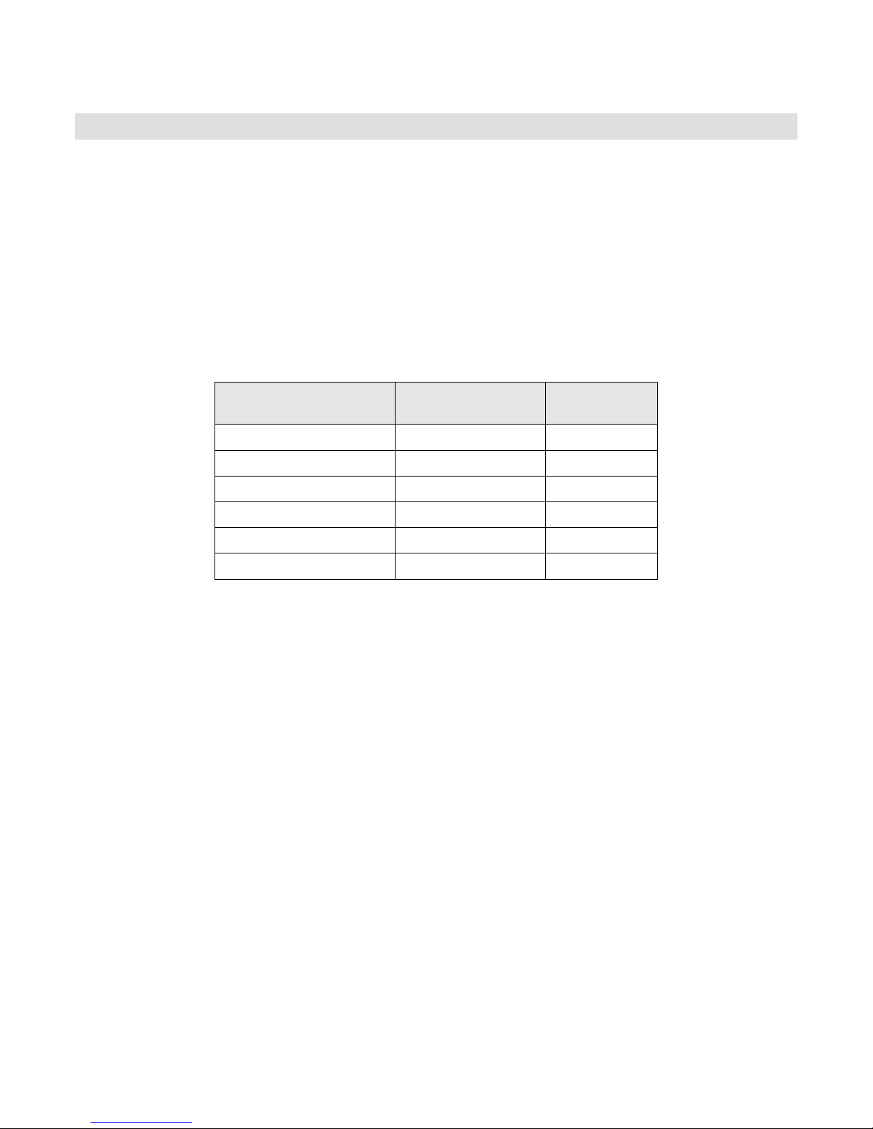
Dell
Resolution
Refresh Rate (Hz)
Color Depth
(bit)
640 x 480
60, 72, 75, 85
8, 16, 32
800 x 600
56, 60, 72, 75, 85
8, 16, 32
1024 x 768
60, 72, 75, 85
8, 16, 32
1152 x 864
75
8, 16, 32
1280 x 1024
60, 75, 85
8, 16
1280 x 1024
60
32
14 Video
The R910 Integrated Dell Remote Access Controller 6 (iDRAC6) incorporates an integrated video
subsystem, connected to the 32-bit PCI interface of the ICH10. This logic is based on the Matrox
G200. The device only supports 2D graphics.
The video device outputs are multiplexed between the front and rear video ports. If a monitor is
connected to the front video connector, it will take precedence over the rear connection, thereby
removing the display from the rear connection.
The integrated video core shares its video memory with the iDRAC6’s 128 MB DDR2 application space
memory. This memory is also used for the KVM buffer.
The R910 system supports the following 2D graphics video modes:
Table 13. Supported Video Modes
Dell PowerEdge R910 Technical Guide 55
Page 56

Dell
15 Audio
R910 does not support speakers or audio output.
Dell PowerEdge R910 Technical Guide 56
Page 57
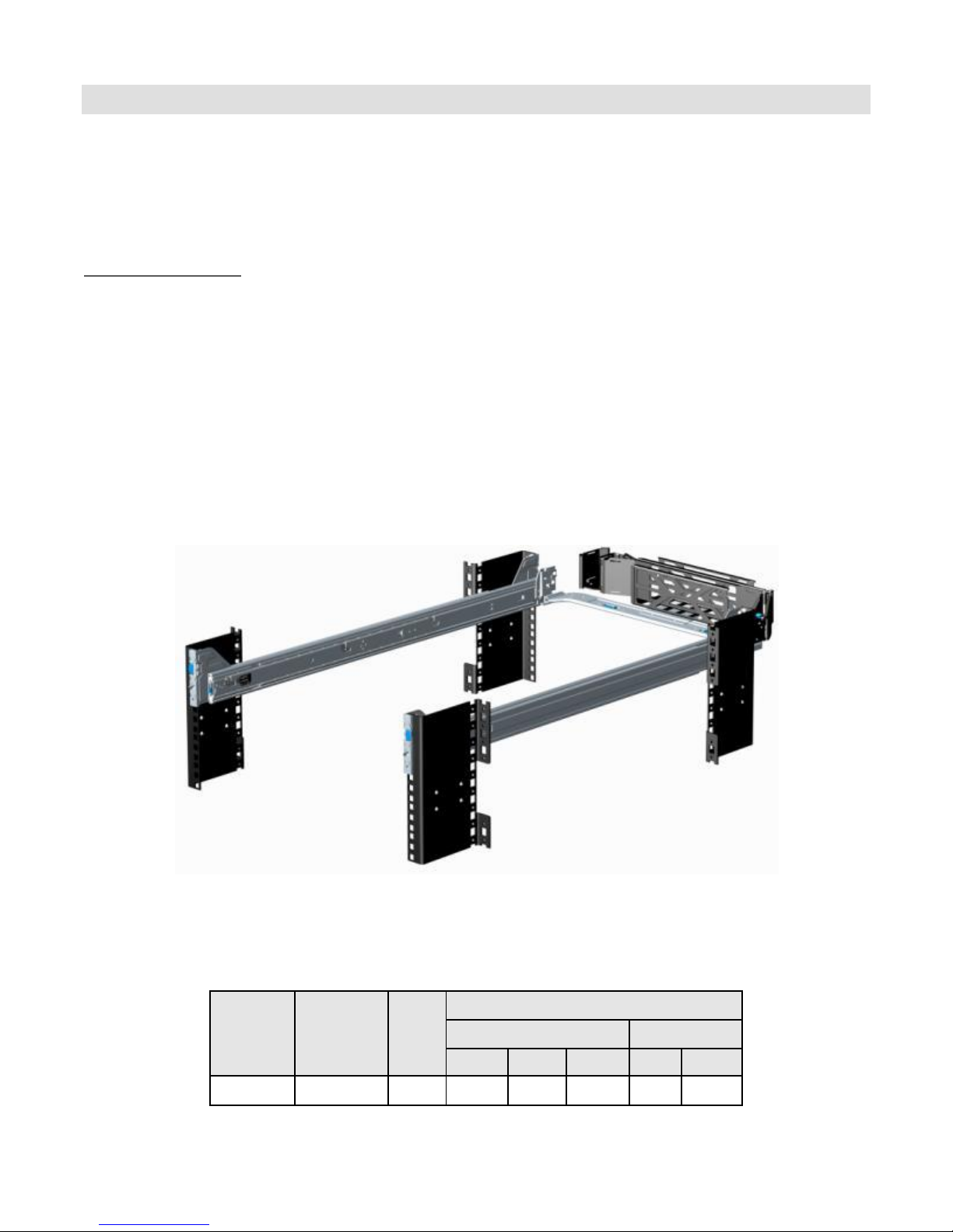
Dell
Rail
Identifier
Mounting
Interface
Rail
Type
Rack Types Supported
4-Post
2-Post
Square
Round
Thread
Flush
Center
B2
ReadyRails™
Sliding
√
√
X X X
16 Rack Information
16.1 Overview
The ReadyRails™ sliding rail system for the R910 provides tool-less support for racks with square or
unthreaded round mounting holes including all generations of Dell racks. The optional cable
management arm (CMA) can be mounted on either the left or right side of the sliding rails without
the use of tools for fast and easy deployment.
IMPORTANT NOTES:
The R910 is not compatible with any other Dell rails including previous generation rails, but it
does use the same rails as the R810 & R815.
The R910 supports sliding rails only. Static rails are not supported.
Threaded hole racks require Dell’s fixed shelf or adapter brackets available from
RackSolutions.
The CMA is not supported on racks that are less than 1m in depth including Dell’s 4200 & 2400
racks.
16.2 Rails
The ReadyRails sliding rails for the R910 support tool-less mounting in 19‖-wide, EIA-310-E compliant
square hole and unthreaded round hole racks and are available with or without the optional cable
management arm (CMA).
Figure 23. R910 ReadyRails Sliding Rails with Optional CMA
As noted below, the R910 rails do not support mounting in threaded hole or 2-post racks*.
Table 14. Rack Types Supported by the R910
Dell PowerEdge R910 Technical Guide 57
Page 58
Dell
Rail Adjustability Range (mm)
Rail Depth
(mm)
Square
Round
Threaded
without
CMA
with
CMA
Min
Max
Min
Max
Min
Max
686
883
672
876 - -
755
883
*Adapter brackets are available from RackSolutions that allow the R910 sliding rails to mount in threaded
racks. The only option available for 2-post racks is to mount the system on a fixed shelf.
Other factors to consider when deploying the R910 include the spacing between the front and rear
mounting flanges of the rack, the type and location of any equipment mounted in the back of the
rack such as power distribution units (PDUs), and the overall depth of the rack. For example, use of
the CMA requires racks that are a minimum of 1m in depth with the PDUs or other rack accessories
positioned on the sides or rear of the rack away from the CMA.
Table 15. Rail Adjustability Range and Depth
NOTE: The min-max values listed above represent the allowable distance between the front and rear
mounting flanges in the rack. Rail depth without the CMA represents the minimum depth of the rail
with the outer CMA brackets removed (as measured from the front mounting flanges of the rack).
16.3 Cable Management Arm (CMA)
The optional cable management arm (CMA) for the R910 organizes and secures the cords and cables
exiting the back of the server and unfolds to allow the server to extend out of the rack without
having to detach the cables. Some key features of the R910 CMA include:
Large U-shaped baskets to support dense cable loads
Open vent pattern for optimal airflow
Fully reversible (can be mounted on either side) with no conversion required
Utilizes hook-and-loop straps rather than plastic tie wraps to eliminate the risk of cable
damage during cycling
Includes a low profile fixed tray to both support and retain the CMA in its fully closed position
Both the CMA and the tray mount without the use of tools via simple and intuitive snap-in
designs
16.4 Rack View
The R910 ReadyRails sliding rails are a ―drop-in‖ design, meaning that the system is installed
vertically into the rails by inserting the shoulder nuts on the sides of the system into the J-slots in
the inner rail members with the rails in the fully extended position.
Dell PowerEdge R910 Technical Guide 58
Page 59
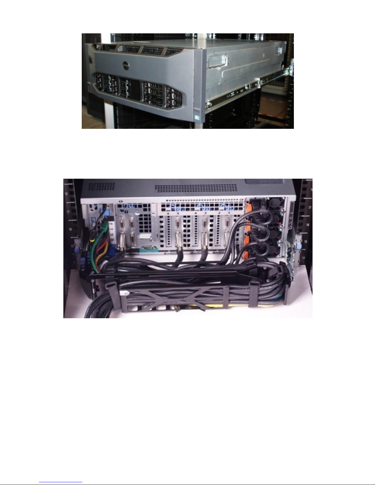
Dell
Figure 24. R910 Mounted in the B2 Sliding Rails
The R910 CMA can be mounted to either side of the rails without the use of tools or the need for
conversion, but it is recommended that it be mounted on the side opposite the power supplies to
allow easier access to the power supplies for service or replacement.
Figure 25. R910 CMA Mounted on the Side Opposite the Power Supplies (Recommended)
Dell PowerEdge R910 Technical Guide 59
Page 60

Dell
17 Operating Systems
For the most up-to-date information, see the Operating System Support Matrix for Dell PowerEdge
Systems on Dell.com.
Dell PowerEdge R910 Technical Guide 60
Page 61

Dell
18 Virtualization
The following virtualization software is supported:
Microsoft Windows Server 2008 Hyper-V
VMware ESXi Version 4.0 update1
Citrix
®
XenServer™ 5.6
Dell PowerEdge R910 Technical Guide 61
Page 62

Dell
19 Systems Management
19.1 Overview/Description
Dell aims on delivering open, flexible, and integrated solutions that help you reduce the complexity
of managing disparate IT assets by building comprehensive IT management solutions. Combining Dell
PowerEdge Servers with a wide selection of Dell-developed management solutions gives you choice
and flexibility, so you can simplify and save in environments of any size. To help you meet your
server performance demands, Dell offers Dell OpenManage™ systems management solutions for:
• Deployment of one or many servers from a single console
• Monitoring of server and storage health and maintenance
• Update of system, operating system, and application software
Dell offers IT management solutions for organizations of all sizes—priced, sized, and supported right.
19.2 Server Management
A Dell Systems Management and Documentation DVD and a Dell Management Console DVD are
included with the product. ISO images are also available. A brief description of available content:
• Dell Systems Build and Update Utility: Dell Systems Build and Update Utility assists in OS
install and pre-OS hardware configuration and updates.
• OpenManage Server Administrator: The OpenManage Server Administrator (OMSA) tool
provides a comprehensive, one-to-one systems management solution, designed for system
administrators to manage systems locally and remotely on a network. OMSA allows system
administrators to focus on managing their entire network by providing comprehensive one-toone systems management.
• Management Console: Our legacy IT Assistant console is also included, as well as tools to allow
access to our remote management products. These tools are Remote Access Service, for
iDRAC, and the BMC Management Utility.
• Active Directory Snap-in Utility: The Active Directory Snap-in Utility provides an extension
snap-in to the Microsoft Active Directory. This allows you to manage Dell specific Active
Directory objects. The Dell-specific schema class definitions and their installation are also
included on the DVD.
• Dell Systems Service Diagnostics Tools: Dell Systems Service and Diagnostics tools deliver the
latest Dell optimized drivers, utilities, and operating system-based diagnostics that you can
use to update your system.
• eDocs: The section includes Acrobat files for PowerEdge systems, storage peripheral, and
OpenManage software.
• Dell Management Console DVD: The Dell Management Console is a Web-based systems
management software that enables you to discover and inventory devices on your network. It
also provides advanced functions, such as health and performance monitoring of networked
devices and patch management capabilities for Dell systems.
• Server Update Utility: In addition to the Systems Management Tools and Documentation and
Dell Management Console DVDs, customers have the option to obtain Server Update Utility
DVD. This DVD has an inventory tool for managing updates to firmware, BIOS and drivers for
either Linux or Windows varieties.
Dell PowerEdge R910 Technical Guide 62
Page 63
Dell
Feature
Description
Faster O/S Installation
Drivers and the installation utility are embedded on system, so no
need to scour DELL.COM
Faster System Updates
Integration with Dell support automatically directed to latest versions
of the Unified Server Configurator, iDRAC, RAID, BIOS, NIC, and
Power Supply
Update Rollback
Ability to recover to previous “known good state” for all updatable
components
More Comprehensive Diagnostics
Diagnostic utilities are embedded on system
Simplified Hardware Configuration
Detects RAID controller and allows user to configure virtual disk and
choose virtual disk as boot device, eliminating the need to launch a
separate utility. Also provides configuration for iDRAC, BIOS, and
NIC/LOM.
19.3 Embedded Server Management
The PowerEdge R910 implements circuitry for the next generation of Embedded Server Management.
It is Intelligent Platform Management Interface (IPMI) v2.0 compliant. The optional iDRAC (Integrated
Dell Remote Access Controller) is responsible for acting as an interface between the host system and
its management software and the periphery devices.
The optional upgrade to iDRAC6 provides features for managing the server remotely or in data center
lights-out environments.
Advanced iDRAC features require the installation of the optional iDRAC6 Enterprise card.
19.4 Lifecycle Controller and Unified Server Configurator
Embedded management is comprised of several interdependent pieces:
• Lifecycle Controller
• Unified Server Configurator
• iDRAC6
• vFlash
Lifecycle controller powers the embedded management features. It is integrated and tamperproof
storage for system-management tools and enablement utilities (firmware, drivers, etc.). It is flash
partitioned to support multiple, future-use cases.
Dell Unified Server Configurator (USC) is a local 1:1 graphical user interface embedded on Lifecycle
Controller that aids in local server provisioning in a pre-OS environment. For servers with iDRAC
Express, the Lifecycle Controller offers OS install, platform updates, platform configuration, and
diagnostics capabilities. For servers without iDRAC Express, this utility has limited functionality and
offers OS install and diagnostics capabilities only.
To access the Unified Server Configurator, press the <F10> key within 10 seconds of the Dell logo’s
appearance during the system boot process. Current functionality enabled by the Unified Server
Configurator includes:
Table 16. Unified Server Configurator Features and Description
Dell PowerEdge R910 Technical Guide 63
Page 64
Dell
Feature
BMC
iDRAC 6 Express
iDRAC6 Enterprise
vFlash Media
Interface and Standards Support
IPMI 2.0
Web-based GUI
SNMP
WSMAN
SMASH-CLP
Racadm commandline
Conductivity
Shared/Failover
Network Modes
IPv4
19.5 Optional iDRAC Express
The optional iDRAC Express is the first tier of iDRAC6 upgrades. In addition to upgrading the system
with a Lifecycle Controller, the iDRAC6 Express offers the following key features:
• Graphical web interface
• Standard-based interfaces
• Server Sensor monitoring and fault alerting
• Secure operation of remote access functions including authentication, authorization, and
encryption
• Power control and management with the ability to limit server power consumption and
remotely control server power states
• Advanced troubleshooting capabilities
For more information on iDRAC6 Express features see table below.
19.6 iDRAC6 Enterprise
The optional iDRAC6 Enterprise card provides access to advanced iDRAC6 features. The iDRAC6
Enterprise connects directly to the R910 planar and is mounted parallel to the planar with stand-offs.
Key features for the iDRAC6 Enterprise include:
• Scripting capability with Dell’s Racadm command-line
• Remote video, keyboard, and mouse control with Virtual Console
• Remote media access with Virtual Media
• Dedicated network interface
Additionally, the iDRAC6 Enterprise can be upgraded by adding the vFlash Media card. This is a 1 GB
Dell branded SD card that enables a persistent 256 MB virtual flash partition. In the future, vFlash
will be expanded to include additional features.
A more detailed feature list for iDRAC6 Enterprise and vFlash is included in the table below.
Table 17. Features List for BMC, iDrac, and vFlash
Dell PowerEdge R910 Technical Guide 64
Page 65
Dell
Feature
BMC
iDRAC 6 Express
iDRAC6 Enterprise
vFlash Media
VLAN Tagging
IPv6
Dynamic DNS
Dedicated NIC
Security and Authentication
Role-based
Authority
Local Users
Active Directory
SSL Encryption
Remote Management and Remediation
Remote Firmware
Update
Server power
control
Serial-over-LAN
(with proxy)
Serial-over-LAN (no
proxy)
Power capping
Last crash screen
capture
Boot capture
Serial-over-LAN
Virtual media
Virtual console
Virtual console
sharing
Virtual flash
Monitoring
Sensor Monitoring
and Alerting
Real-time Power
Monitoring
Real-time Power
Graphing
Historical Power
Counters
Logging Features
Dell PowerEdge R910 Technical Guide 65
Page 66

Dell
Feature
BMC
iDRAC 6 Express
iDRAC6 Enterprise
vFlash Media
System Event Log
RAC Log
Trace Log
Dell PowerEdge R910 Technical Guide 66
Page 67
Dell
Type
Model
SAN Support
EMC's AX Arrays (SCSI, FC and iSCSI)
EMC's CX Arrays (SCSI, FC and iSCSI)
Equal Logic's PS5XXX Arrays (iSCSI)
SAS Management SW for xBOD
OMSS for MD1000
OMSS for MD1020
PowerVault NAS
Attachment to PV NX1950 including iSCSI and clustering
support
Attachment to Win Storage Server on PE
Attachment to EMC NS500G (S&P)
PV DAS
MD1000 JBOD
MD3000 RBOD
MD1120 2.5 SAS/SATA JBOD
MD1100 3.5 SAS/SATA JBOD
PV SAN
MD3000i iSCSI RAID array
EqualLogic™
PS5000 family
PS5500 family
IDM
IDM support
SAS xBOD SW
OpenManage Storage Manager
20 Peripherals
20.1 USB peripherals
PE R910 supports the following USB devices:
DVD (bootable; requires two USB ports)
USB Key (bootable)
Keyboard (only one USB keyboard is supported)
Mouse (only one USB mouse is supported
20.2 External Storage
Table 18. External Storage
Dell PowerEdge R910 Technical Guide 67
Page 68
Dell
Standard
URL for Information and Specifications
ACPI
Advance Configuration and
Power Interface
Specification, v2.0c
http://www.acpi.info/
Ethernet
IEEE 802.3-2005
http://standards.ieee.org/getieee802/802.3.html
IPMI
Intelligent Platform
Management Interface, v2.0
http://www.intel.com/design/servers/ipmi/
DDR3 Memory
DDR3 SDRAM Specification,
Rev. 3A
http://www.jedec.org/download/search/JESD79-3A.pdf
LPC
Low Pin Count Interface
Specification, Rev. 1.1
http://developer.intel.com/design/chipsets/industry/lpc.htm
PCI Express
PCI Express Base
Specification Rev. 2.0
http://www.pcisig.com/specifications/pciexpress/
PMBus
Power System Management
Protocol Specification, v1.1
http://pmbus.info/specs.html
SAS
Serial Attached SCSI, v1.1
http://www.t10.org/ftp/t10/drafts/sas1/sas1r10.pdf
SATA
Serial ATA Rev. 2.6;
SATA II, Extensions to SATA
1.0a, Rev. 1.2
https://www.sata-io.org/secure/spec_download.asp
http://www.sata-io.org/docs/S2Ext_1_2_Gold.pdf
SMBIOS
System Management BIOS
Reference Specification, v2.6
http://www.dmtf.org/standards/smbios/
TPM
Trusted Platform Module
Specification, v1.2
https://www.trustedcomputinggroup.org/downloads/specific
ations/tpm/tpm
UEFI
Unified Extensible Firmware
Interface Specification, v2.1
http://www.uefi.org/specs/
USB
Universal Serial Bus
Specification, Rev. 2.0
http://www.usb.org/developers/docs/
Appendix A. Regulatory Certifications
Table 19. Standards Compliance
Dell PowerEdge R910 Technical Guide 68
Page 69

Dell
Standard
URL for Information and Specifications
Windows Logo
Windows Logo Program
System and Device
Requirements, v3.10
http://www.microsoft.com/whdc/winlogo/hwrequirements.
mspx
Dell PowerEdge R910 Technical Guide 69
Page 70
Dell
Server BIOS Memory (SPI Flash, IC)
Size:
4 MB
Type [e.g., Flash PROM, EEPROM]:
Flash EEPROM (Serial Peripheral Interface)
Can user programs or operating system
write data to it during normal operation?
No
Does it retain data when powered off?
Yes
Purpose? [e.g., boot code]
Boot Code, Configuration Information, EUFI
environment
How is data input to this memory?
Loading flash memory requires a vendorprovided firmware file and loader program
which is executed by booting up the system
from a floppy or OS-based executable containing
the firmware file and the loader. System loaded
with arbitrary data in firmware memory will not
operate.
How is this memory write protected?
Software write protected
Server CMOS (Complementary Metal-Oxide Semiconductor) Memory
Size:
512 Bytes
Type [e.g., Flash PROM, EEPROM]:
Battery-Backed NVRAM
Can user programs or operating system
write data to it during normal operation?
No
Does it retain data when powered off?
Yes
Purpose? [e.g., boot code]
RTC and storing system configuration settings
How is data input to this memory?
F2 Setup Menu during POST
How is this memory write protected?
N/A
Remarks
Jumper on motherboard can be used to clear to
factory default settings.
Removing CMOS battery will clear to factory
defaults settings as well.
Server BMC (Baseboard Management Controller)/iDRAC Express Boot Block Flash
Size:
2 MB
Type [e.g., Flash PROM, EEPROM]:
Serial Flash
Can user programs or operating system
write data to it during normal operation?
No
Does it retain data when powered off?
Yes
Purpose? [e.g., boot code]
iDRAC boot loader and configuration (i.e. MAC
address), Lifecycle log.
How is data input to this memory?
Data pre-programmed or update using Dell
utility which is a DOS or Windows or Linux based
Appendix B. R910 Volatility Table
Table 20. R910 Volatility
Dell PowerEdge R910 Technical Guide 70
Page 71
Dell
executable containing firmware file and loader
How is this memory write protected?
Software write protected
Remarks
Bad contents yield the iDRAC inoperable and is
unrecoverable in the customer environment.
Note the lifecycle log is automatically updated
by the iDRAC as various system component FW,
HW and SW versions are changed.
Server BMC/iDRAC Express Internal Flash
Size:
1 GB
Type [e.g., Flash PROM, EEPROM]:
NAND Flash
Can user programs or operating system
write data to it during normal operation?
No
Does it retain data when powered off?
Yes
Purpose? [e.g., boot code]
iDRAC Operating System plus Managed System
Services Repository (i.e., Unified Server
Configurator, OS drivers, diagnostics, rollback
versions of various programmables)
How is data input to this memory?
iDRAC OS: Loading flash memory requires a
vendor-provided firmware file and loader
program which is executed by booting up the
system from a floppy or OS-based executable
containing the firmware file and the loader.
System loaded without a good iDRAC firmware
image yields a non-functional iDRAC.
Managed Services Repository: Various partitions
are loaded via vendor-provided firmware file
and loader program just like iDRAC OS.
How is this memory write protected?
Software write protected
System Event Log (SEL) Memory and Baseboard FRU
Size:
4 KB
Type [e.g., Flash PROM, EEPROM]:
SERIAL EEPROM
Can user programs or operating system
write data to it during normal operation?
No
Does it retain data when powered off?
Yes
Purpose? [e.g., boot code]
Store system events from BMC and BIOS. FRU
information for board such as PPID, MAC
addresses etc.
How is data input to this memory?
For SEL, BMC writes to it.
For FRU, data is pre-programmed or input using
Dell utility at ICT/Functional Tester during
board assembly.
How is this memory write protected?
Software write protected
FRU Memory for the I/O Risers (1GbE or 10Gb) and Memory Riser
Size:
256 Bytes
Dell PowerEdge R910 Technical Guide 71
Page 72
Dell
Type [e.g., Flash PROM, EEPROM]:
EEPROM
Can user programs or operating system
write data to it during normal operation?
No
Does it retain data when powered off?
Yes
Purpose? [e.g., boot code]
FRU information for boards such as board name,
PPID, manufacturing date etc.
How is data input to this memory?
Data pre-programmed or using Dell utility at
ICT/Functional Tester during board assembly.
How is this memory write protected?
Not write protected
DIMM Modules SPD (Serial Presence Detect) EEPROM
(up to 64 depending on the number of DIMM modules present)
Size:
256 Bytes
Type [e.g., Flash PROM, EEPROM]:
EEPROM
Can user programs or operating system
write data to it during normal operation?
No
Does it retain data when powered off?
Yes
Purpose? [e.g., boot code]
DIMM information and temperature settings
How is data input to this memory?
Data preprogrammed by the DIMM vendors
(lower 128 bytes). Also during boot sequence,
data is written to SPD EEPROM (upper 128
Bytes).
How is this memory write protected?
Not write protected
TPM (Trusted Platform Module) (if applicable)
Size:
128 Bytes
Type [e.g., Flash PROM, EEPROM]:
EEPROM
Can user programs or operating system
write data to it during normal operation?
No
Does it retain data when powered off?
Yes
Purpose? [e.g., boot code]
Stores encryption keys for TPM functionality
How is data input to this memory?
Data is pre-programmed by vendor. Keys are
updated using TPM-enabled operating systems.
How is this memory write protected?
Software write protected
Remarks
F2 BIOS setup option to enable/activate/clear
TPM Alternative Plug-in Module (if applicable)
Size:
256 Bytes
Type [e.g., Flash PROM, EEPROM]:
EEPROM
Can user programs or operating system
write data to it during normal operation?
No
Does it retain data when powered off?
Yes
Purpose? [e.g., boot code]
Stores encryption keys for TPM functionality
Dell PowerEdge R910 Technical Guide 72
Page 73
Dell
How is data input to this memory?
Data is pre-programmed by vendor. Keys are
updated using TPM enabled operating systems.
How is this memory write protected?
Software write protected
Remarks
F2 BIOS setup option to enable/activate/clear
Server CPLD Devices (x2 per baseboard)
Size:
2280 macro-cells and 256 macro-cells
Type [e.g., Flash PROM, EEPROM]:
Internal Flash EEPROM
Can user programs or operating system
write data to it during normal operation?
No
Does it retain data when powered off?
Yes
Purpose? [e.g., boot code]
System power sequence control, error/config
detection, and BIOS-BMC interaction.
How is data input to this memory?
Programming CPLD(s) requires a vendorprovided logic file and loader program which is
executed by booting up the system from a
floppy or OS-based executable containing the
logic file and the loader. System loaded with
arbitrary data in CPLD(s) will not operate.
How is this memory write protected?
Software write protected
Remarks
Need AC cycle after updating CPLD
Broadcom® 5709/57711 PCI-e Network Interface Controller Flash
Size:
1MB
Type [e.g., Flash PROM, EEPROM]:
Serial Flash
Can user programs or operating system
write data to it during normal operation?
No
Does it retain data when powered off?
Yes
Purpose? [e.g., boot code]
Embedded Network Controller FW and config
data
How is data input to this memory?
Loading flash memory requires a vendorprovided firmware file and loader program
which is executed by booting up the system
from a floppy or OS-based executable
containing the firmware file and the loader.
System loaded with arbitrary data in firmware
memory would not have the network ports
operational.
How is this memory write protected?
Software write protected
Remarks
There is a quantity of 2 SPI flash on both the I/O
risers. On 1GbE I/O riser, both flash parts are
for the two 5709C controllers where as on 10Gb
I/O riser, one is for 5709C and the other one is
for 57711 network controller.
Broadcom 8727 PHY (Physical Layer) EEPROM (applicable to only 10Gb I/O riser)
Size:
32KB
Dell PowerEdge R910 Technical Guide 73
Page 74
Dell
Type [e.g., Flash PROM, EEPROM]:
Serial EEPROM
Can user programs or operating system
write data to it during normal operation?
No
Does it retain data when powered off?
Yes
Purpose? [e.g., boot code]
Stores the PHY firmware
How is data input to this memory?
Data is preprogrammed or update using Dell
LOM FW update utility. System loaded with
arbitrary data in firmware memory will not have
the 10Gb SFP+ network ports operational
How is this memory write protected?
Software write protected
Remarks
10Gb I/O riser is optional
10 Gb I/O riser CPLD (applicable to only 10Gb I/O riser when present)
Size:
64 Macrocells
Type [e.g., Flash PROM, EEPROM]:
CPLD
Can user programs or operating system write
data to it during normal operation?
No
Does it retain data when powered off?
Yes
Purpose? [e.g., boot code]
Stores the standby power delivery routing to
10Gb network controller and its PHY
How is data input to this memory?
Data is preprogrammed at board build
How is this memory write protected?
Software write protected
Remarks
10Gb I/O riser is optional
Dell PERC H700i storage controller CPLD/Flash/NVSRAM etc. (if applicable)
Size:
FRU: 256 Bytes
Boot ROM: 8 KB
Flash: 8 MB
CPLD: 128 Macrocells
NVSRAM: 128 KB
iButton key EEPROM: 128 Bytes
Battery-Backed Cache: 512 MB
Type [e.g., Flash PROM, EEPROM]:
FRU, EEPROM, Flash, CPLD, Non-volatile SRAM
and a 1-wire EEPROM
Can user programs or operating system write
data to it during normal operation?
No
Does it retain data when powered off?
Yes
Purpose? [e.g., boot code]
Flash stores the storage controllers firmware
CPLD controls the power sequencing & battery
backup logic
NVSRAM stores the controller configuration
FRU stores the PPID, manufacturing date etc.
Battery-Backed Cache: Stores the data if the
cache is not cleared and battery backup unit is
Dell PowerEdge R910 Technical Guide 74
Page 75

Dell
enabled in the case of a power loss.
How is data input to this memory?
FRU/CPLD data is preprogrammed at board
build.
NVSRAM is updated by the storage controller
Flash is updated by Dell provided update
package
Cache stores the data before getting written to
the disks when WriteBack policy is enabled with
battery backup.
How is this memory write protected?
FRU is not write protected but other
components detailed above in the Size row are
software write protected.
Remarks
PERC H700i controller is optional
Dell PERC H200i storage controller Flash/NVSRAM/FRU (if applicable)
Size:
FRU: 256 Bytes
Boot ROM: 8 KB
Flash: 8 MB
NVSRAM: 128 KB
Type [e.g., Flash PROM, EEPROM]:
Flash (NOR), EEPROM and NVSRAM
Can user programs or operating system write
data to it during normal operation?
No
Does it retain data when powered off?
Yes
Purpose? [e.g., boot code]
Flash stores the storage controllers firmware
NVSRAM stores the controller configuration
FRU stores the PPID, manufacturing date etc.
How is data input to this memory?
FRU data is preprogrammed at board build.
NVSRAM is updated by the storage controller
Flash is updated by Dell provided update
package
How is this memory write protected?
FRU is not write protected but everything else is
software write protected
Remarks
PERC H200i controller is optional
Server (4- or 16-drive SAS) Backplane Storage Controller Memory
Size:
32KB
Type [e.g., Flash PROM, EEPROM]:
Embedded Microcontroller Flash
Can user programs or operating system write
data to it during normal operation?
No
Does it retain data when powered off?
Yes
Purpose? [e.g., boot code]
Stores the server storage backplane FW and FRU
Dell PowerEdge R910 Technical Guide 75
Page 76

Dell
How is data input to this memory?
Loading flash memory requires a vendorprovided firmware file and loader program
which is executed by booting up the system
from a floppy or OS-based executable
containing the firmware file and the loader.
System loaded with arbitrary data in firmware
memory would not operate.
How is this memory write protected?
Software write protected
Remarks
There is quantity of ―1‖ PSoC device on the 4drive backplane versus ―2‖ on the 16-drive
backplane.
Server (16-drive SAS only) Backplane SAS Expander EEPROM
Size:
4MB
Type [e.g., Flash PROM, EEPROM]:
Flash EEPROM
Can user programs or operating system write
data to it during normal operation?
No
Does it retain data when powered off?
Yes
Purpose? [e.g., boot code]
Store SAS expander firmware and configuration
data
How is data input to this memory?
Data pre-programmed or update using Dell
utility which is a DOS-based executable
containing the firmware file and loader.
How is this memory write protected?
Software write protected
Remarks
Ensure that SAS x16 BP cables are attached to
planar prior to update. After update, the
system should be AC cycled before update takes
effect.
Power Supply Firmware and FRU (Field Replacement Unit) Memory
Size:
1100W LiteOn: 4KB FLASH with 256 Bytes RAM
1100W/750W Emerson: 8K and 16K FLASH with
384 and 1024 Bytes RAM respectively
750W Delta: Flash ROM size 48K bytes and
EEPROM size 1K bytes
Type [e.g., Flash PROM, EEPROM]:
FLASH, EEPROM
Can user programs or operating system write
data to it during normal operation?
No
Does it retain data when powered off?
Yes
Purpose? [e.g., boot code]
Stores PSU controller firmware. FRU information
for boards such as name, manufacturing date
etc.
How is data input to this memory?
FRU and firmware data pre-programmed by the
PSU vendors. PSU firmware can be updated by
Dell provided update package.
How is this memory write protected?
Software write protected
Remarks
The number of these devices depends on the
Dell PowerEdge R910 Technical Guide 76
Page 77
Dell
number of PSUs installed.
Dell Internal Dual SD Module (IDSM) microcontroller flash (if present)
Size:
256 KB
Type [e.g., Flash PROM, EEPROM]:
EEPROM
Can user programs or operating system write
data to it during normal operation?
No
Does it retain data when powered off?
Yes
Purpose? [e.g., boot code]
Store firmware for IDSM functionality
How is data input to this memory?
Loading flash memory requires a vendorprovided firmware file and loader program.
IDSDM module loaded with arbitrary data in
firmware memory would not operate.
How is this memory write protected?
Software write protected
Remarks
IDSM is an option
Dell Internal Dual SD Module (IDSM) write journal flash (if present)
Size:
8 MB
Type [e.g., Flash PROM, EEPROM]:
EEPROM
Can user programs or operating system write
data to it during normal operation?
No
Does it retain data when powered off?
Yes
Purpose? [e.g., boot code]
Store write journal for shutdown recovery
How is data input to this memory?
IDSM microcontroller writes to and read from
these memory via SPI interface during
operation.
How is this memory write protected?
Software write protected
Remarks
IDSM is an option
SD card(s) (if present) for IDSM (one or two SD cards depending on the redundancy mode
ordered with it)
Size:
Multiple (1GB, 2GB, 8GB)
Type [e.g., Flash PROM, EEPROM]:
Secure Digital NAND Flash
Can user programs or operating system write
data to it during normal operation?
No
Does it retain data when powered off?
Yes
Purpose? [e.g., boot code]
Normal usage is embedded Hypervisor OS but
not limited
How is data input to this memory?
Factory load, OS run time usage and OS updates
and configuration changes.
How is this memory write protected?
Media-write protection or software-write
protected
Remarks
IDSM is an option
Dell PowerEdge R910 Technical Guide 77
Page 78

Dell
vFlash for iDRAC Enterprise
Size:
Multiple
Type [e.g., Flash PROM, EEPROM]:
Secure Digital NAND Flash
Can user programs or operating system write
data to it during normal operation?
No
Does it retain data when powered off?
Yes
Purpose? [e.g., boot code]
Storage of logs, user images like files, drivers,
OS’s etc.
How is data input to this memory?
Preloaded media before installation, or remote
out-of-band upload of user data (i.e., ISO
images, files) or local server read/write
capability to use like a hard disk.
How is this memory write protected?
Media write protection or Software write
protected
Remarks
iDRAC Enterprise and vFlash are optional
Dell PowerEdge R910 Technical Guide 78
 Loading...