

Page 1

Dell PowerEdge VRTX Enclosure
Owner's Manual
Regulatory Model: E22S
Regulatory Type: E22S001
Page 2

Notes, Cautions, and Warnings
NOTE: A NOTE indicates important information that helps you make better use of your computer.
CAUTION: A CAUTION indicates either potential damage to hardware or loss of data and tells you how to avoid the
problem.
WARNING: A WARNING indicates a potential for property damage, personal injury, or death.
© 2013 Dell Inc.
Trademarks used in this text: Dell™, the Dell logo, Dell Boomi™, Dell Precision™ , OptiPlex™, Latitude™, PowerEdge™, PowerVault™,
PowerConnect™, OpenManage™, EqualLogic™, Compellent™, KACE™, FlexAddress™, Force10™ and Vostro™ are trademarks of Dell
Inc. Intel®, Pentium®, Xeon®, Core® and Celeron® are registered trademarks of Intel Corporation in the U.S. and other countries. AMD
is a registered trademark and AMD Opteron™, AMD Phenom™ and AMD Sempron™ are trademarks of Advanced Micro Devices, Inc.
Microsoft®, Windows®, Windows Server®, Internet Explorer®, MS-DOS®, Windows Vista® and Active Directory® are either trademarks
or registered trademarks of Microsoft Corporation in the United States and/or other countries. Red Hat® and Red Hat
Enterprise Linux® are registered trademarks of Red Hat, Inc. in the United States and/or other countries. Novell® and SUSE® are
registered trademarks of Novell Inc. in the United States and other countries. Oracle® is a registered trademark of Oracle Corporation
and/or its affiliates. Citrix®, Xen®, XenServer® and XenMotion® are either registered trademarks or trademarks of Citrix Systems, Inc. in
the United States and/or other countries. VMware
trademarks of VMware, Inc. in the United States or other countries.
Corporation.
2013 - 05
®
,
vMotion
®
,
vCenter
®
,
vCenter SRM
®
is a registered trademark of International Business Machines
IBM
™
and
vSphere
®
are registered trademarks or
®
®
Rev. A00
Page 3

Contents
Notes, Cautions, and Warnings...................................................................................................2
1 About Your System......................................................................................................................9
Introduction.............................................................................................................................................................. 9
Terms Used In The Document............................................................................................................................9
System Overview....................................................................................................................................................10
Front-Panel Features And Indicators..................................................................................................................... 12
KVM Features...................................................................................................................................................14
Hard-Drive Indicator Patterns..........................................................................................................................14
LCD Module......................................................................................................................................................15
Back-Panel Features And Indicators..................................................................................................................... 18
Power Supply Indicators..................................................................................................................................19
Blower Module Indicators............................................................................................................................... 20
I/O Module Indicators...................................................................................................................................... 21
CMC Indicators.................................................................................................................................................22
CMC Features...................................................................................................................................................22
CMC Fail-Safe Mode........................................................................................................................................ 23
Configuration Wizard..............................................................................................................................................24
System Messages...................................................................................................................................................24
LCD Messages........................................................................................................................................................24
Other Information You May Need...........................................................................................................................25
2 Initial System Configuration.................................................................................................... 27
Before You Begin....................................................................................................................................................27
Initial Setup Sequence............................................................................................................................................27
Logging In To The CMC...........................................................................................................................................28
3 Configuring Enclosure Components.......................................................................................29
Fabric A...................................................................................................................................................................29
Fabrics B And C...................................................................................................................................................... 29
I/O Module And PCIe Mezzanine Card Configuration Guidelines.......................................................................... 29
Supported I/O Modules...........................................................................................................................................30
Configuring Network Settings For The I/O Module.................................................................................................30
Mapping PCIe Expansion Slots...............................................................................................................................30
Managing PCIe Slots.............................................................................................................................................. 31
Managing Chassis Storage.....................................................................................................................................31
Page 4

4 Installing Enclosure Components...........................................................................................33
Recommended Tools.............................................................................................................................................. 33
Front Bezel (Optional)............................................................................................................................................. 33
Installing The Front Bezel.................................................................................................................................33
Removing The Front Bezel................................................................................................................................34
System Feet—Tower Mode....................................................................................................................................34
Removing The System Feet..............................................................................................................................34
Installing The System Feet............................................................................................................................... 35
Wheel Assembly (Optional)—Tower Mode............................................................................................................35
Installing The Wheel Assembly........................................................................................................................35
Removing The Wheel Assembly.......................................................................................................................38
Opening And Closing The System...........................................................................................................................39
Opening The System........................................................................................................................................ 39
Closing The System..........................................................................................................................................40
Inside The System...................................................................................................................................................40
Hard Drives.............................................................................................................................................................41
Removing A 2.5 Inch Hard-Drive Blank............................................................................................................42
Installing A 2.5 Inch Hard-Drive Blank............................................................................................................. 42
Removing A 3.5 Inch Hard-Drive Blank............................................................................................................42
Installing A 3.5 Inch Hard-Drive Blank............................................................................................................. 43
Removing A Hot-Swap Hard Drive...................................................................................................................43
Installing A Hot-Swap Hard Drive.................................................................................................................... 44
Removing A Hard Drive From A Hard-Drive Carrier.........................................................................................45
Installing A Hard Drive Into A Hard-Drive Carrier............................................................................................46
Server Modules...................................................................................................................................................... 46
Removing A Server Module............................................................................................................................. 47
Configuring A Server Module...........................................................................................................................48
Installing A Server Module...............................................................................................................................49
Power Supplies.......................................................................................................................................................49
Power Supply Blanks....................................................................................................................................... 49
Removing A Power Supply...............................................................................................................................50
Installing A Power Supply................................................................................................................................52
Cooling Shroud....................................................................................................................................................... 53
Removing The Cooling Shroud.........................................................................................................................53
Installing The Cooling Shroud.......................................................................................................................... 54
Cooling Fans............................................................................................................................................................55
Removing A Cooling Fan...................................................................................................................................55
Installing A Cooling Fan....................................................................................................................................56
Cooling-Fan Assembly............................................................................................................................................ 56
Removing The Cooling-Fan Assembly..............................................................................................................56
Installing The Cooling-Fan Assembly...............................................................................................................58
Page 5

Blower Modules..................................................................................................................................................... 58
Removing A Blower Module.............................................................................................................................58
Installing A Blower Module..............................................................................................................................59
Removing The Blower Module Bay..................................................................................................................60
Installing The Blower Module Bay...................................................................................................................60
I/O Module.............................................................................................................................................................. 61
Removing The I/O Module................................................................................................................................61
Installing The I/O Module.................................................................................................................................62
Optical Drive (Optional)...........................................................................................................................................62
Removing The Optical Drive.............................................................................................................................62
Installing The Optical Drive..............................................................................................................................64
CMC Cards..............................................................................................................................................................64
CMC Card Indicators........................................................................................................................................65
Removing A CMC Card.....................................................................................................................................66
Installing A CMC Card...................................................................................................................................... 67
PCIe Cage............................................................................................................................................................... 67
Removing The PCIe Cage Door........................................................................................................................ 67
Installing The PCIe Cage Door......................................................................................................................... 68
Removing The PCIe Cage.................................................................................................................................68
Installing The PCIe Cage..................................................................................................................................71
Expansion Cards..................................................................................................................................................... 71
Expansion Card Installation Guidelines............................................................................................................71
Expansion Card Operational Power Status......................................................................................................72
PCIe Slot Indicators..........................................................................................................................................73
Removing A Low Profile Expansion Card.........................................................................................................74
Installing A Low Profile Expansion Card.......................................................................................................... 75
Removing The Low Profile Expansion Card Divider Unit..................................................................................76
Installing The Low Profile Expansion Card Divider Unit...................................................................................77
Removing A Full Height Expansion Card.......................................................................................................... 78
Installing A Full Height Expansion Card........................................................................................................... 79
Removing The Full-Height Expansion-Card Divider Unit..................................................................................80
Installing The Full Height Expansion Card Divider Unit....................................................................................81
Removing The Expansion Card Riser............................................................................................................... 82
Installing The Expansion Card Riser.................................................................................................................83
Integrated Storage Controller Card........................................................................................................................ 83
Storage Controller Operational Power Status................................................................................................. 84
Storage Controller Indicators...........................................................................................................................85
Removing An Integrated Storage Controller Card........................................................................................... 86
Installing An Integrated Storage Controller Card.............................................................................................87
System Battery....................................................................................................................................................... 88
Replacing The System Battery.........................................................................................................................88
System Top And Base Covers.................................................................................................................................89
Page 6

Removing The System Top And Base Covers..................................................................................................89
Installing The System Top And Base Covers................................................................................................... 90
Mounting Ears.........................................................................................................................................................91
Removing The Mounting Ears.......................................................................................................................... 91
Installing The Mounting Ears........................................................................................................................... 92
Replacing The LCD Module..............................................................................................................................93
Control Panel Assembly..........................................................................................................................................93
Removing The Control Panel............................................................................................................................93
Installing The Control Panel............................................................................................................................. 94
Removing The Control Panel Board................................................................................................................. 95
Installing The Control Panel Board.................................................................................................................. 96
Backplane Expander Boards..................................................................................................................................97
Removing A Backplane Expander Board.........................................................................................................97
Installing A Backplane Expander Board.......................................................................................................... 98
Hard-Drive Backplane............................................................................................................................................ 99
Removing The Hard-Drive Backplane..............................................................................................................99
Installing The Hard-Drive Backplane.............................................................................................................102
Power Distribution Board..................................................................................................................................... 102
Removing The Power Distribution Board.......................................................................................................102
Installing The Power Distribution Board........................................................................................................104
System Board........................................................................................................................................................104
Removing The System Board.........................................................................................................................104
Installing The System Board.......................................................................................................................... 107
Power Pass-Through Board................................................................................................................................. 107
Removing The Power Pass-Through Board...................................................................................................108
Installing The Power Pass-Through Board....................................................................................................109
Midplane...............................................................................................................................................................110
Removing The Midplane.................................................................................................................................110
Installing The Midplane..................................................................................................................................112
5 Converting The System From Tower Mode To Rack Mode............................................. 115
Safety Instructions................................................................................................................................................115
Preparing A System For Conversion From Tower Mode To Rack Mode..............................................................115
Installing The Enclosure In A Rack.......................................................................................................................119
6 Troubleshooting Your System...............................................................................................121
Safety First—For You And Your System............................................................................................................... 121
Responding To A Systems Management Alert Message.....................................................................................121
Troubleshooting External Connections.................................................................................................................121
Troubleshooting A Damaged Enclosure...............................................................................................................121
Troubleshooting Enclosure Components..............................................................................................................122
Troubleshooting A Wet Enclosure................................................................................................................. 122
Page 7

Troubleshooting Power Supplies...................................................................................................................123
Troubleshooting Blower Modules..................................................................................................................123
Troubleshooting The System Battery.............................................................................................................123
Troubleshooting Cooling Problems................................................................................................................124
Troubleshooting Cooling Fans........................................................................................................................124
Troubleshooting An Optical Drive.................................................................................................................. 124
Troubleshooting A Storage Controller........................................................................................................... 125
Troubleshooting Hard Drives......................................................................................................................... 125
Troubleshooting Expansion Cards..................................................................................................................126
Troubleshooting The I/O Module....................................................................................................................127
7 System Board Connectors.....................................................................................................129
8 Technical Specifications....................................................................................................... 133
Enclosure Specifications......................................................................................................................................133
I/O Module Specifications....................................................................................................................................134
Environmental Specifications...............................................................................................................................134
9 Getting Help..............................................................................................................................139
Contacting Dell..................................................................................................................................................... 139
Documentation Feedback.....................................................................................................................................139
Page 8

8
Page 9

About Your System
Introduction
This document provides information on the Dell PowerEdge VRTX enclosure.
Terms Used In The Document
The following table describes the terms used in this document.
Term Description
Enclosure or chassis Refers to the VRTX enclosure.
Server module(s) Refers to Dell PowerEdge M520 or M620 server module(s)
that are specifically configured for the enclosure. For
information about the server modules, see the module's
Owner's Manual at dell.com/poweredgemanuals.
I/O module Refers to an Ethernet pass-through module or a switch
module installed in the chassis.
PCIe mezzanine card(s) Server modules configured for the VRTX enclosure have
PCIe mezzanine cards installed in Fabrics B and C to
provide I/O expansion.
1
NOTE: Ethernet, Fibre Channel, or InfiniBand
mezzanine cards are not supported on the VRTX
enclosure.
PCIe expansion card(s) PCIe cards installed in the enclosure provide I/O
expansion to the chassis.
Warm plug A slot is considered warm plug if the server module
associated with a component in that slot must be turned
off before adding or replacing the component. However,
the chassis and the rest of the server modules remain
powered on.
Hot swap A slot in the chassis is considered as hot swap if a
component can be replaced or installed in it while the
chassis and server modules are powered on.
9
Page 10
System Overview
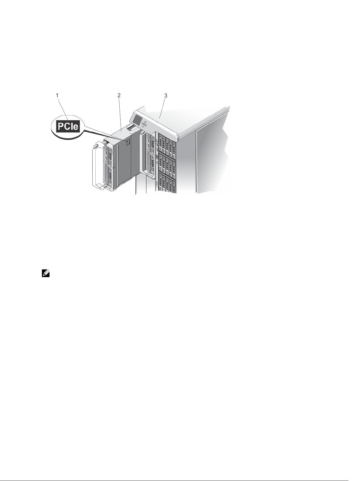
Your system includes up to four Dell PowerEdge M520 or M620 server modules installed in the Dell PowerEdge VRTX
enclosure (chassis) that are specifically configured for the enclosure, and can be identified by a label marked PCIe on
the server module.
Figure 1. Identifying a Server Module Configured for the VRTX Enclosure
1. PCIe label on the server module
2. server module
3. VRTX enclosure
If you install server modules that are not configured for the enclosure, an error message is displayed.
The enclosure supports power supplies, hard drives, Chassis Management Controllers (CMC), blower modules, and an
I/O module. These are shared resources for the server modules.
NOTE: To ensure proper operation and cooling, all bays in the enclosure must be populated at all times with either
a server module or with a blank. Similarly, all empty hard drive slots in the enclosure must be installed with harddrive blanks.
10
Page 11
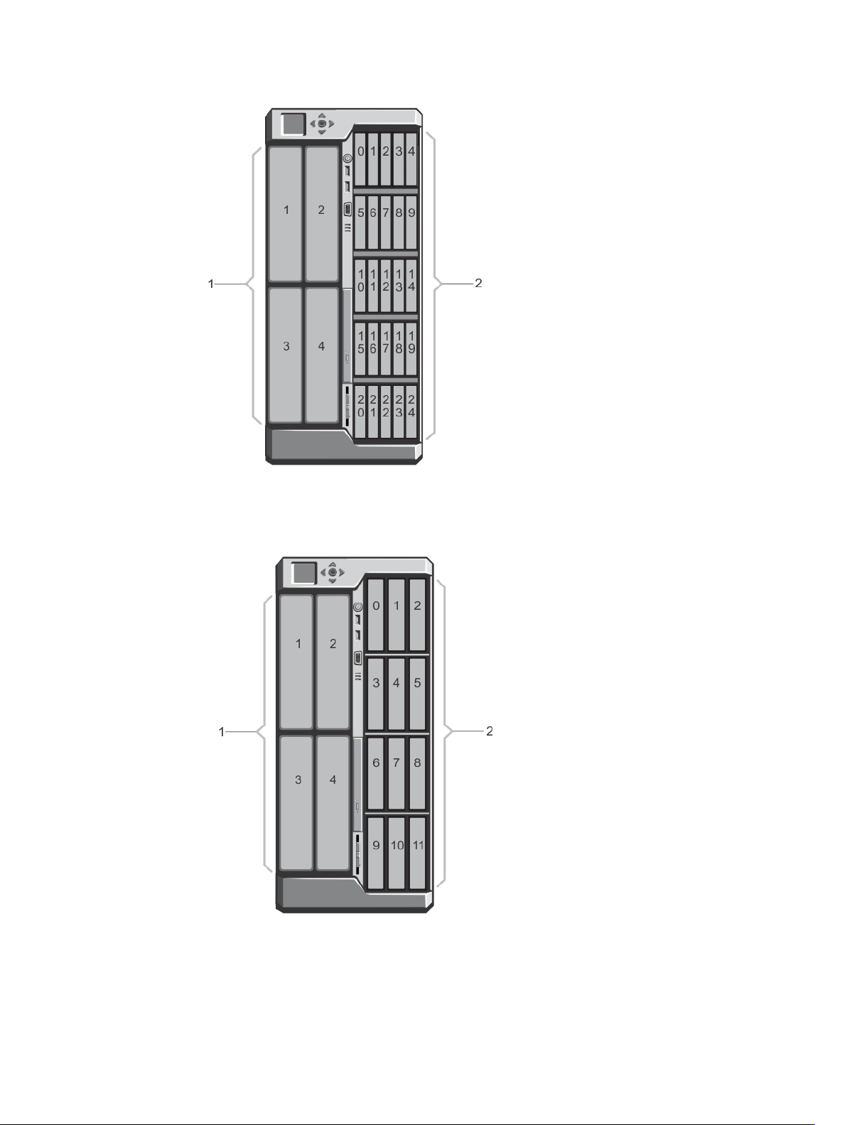
Figure 2. Server Module and Hard-Drive Numbering (2.5 inch Hard-Drive Chassis)
1. server module numbering
2. hard-drive numbering
Figure 3. Server Module and Hard-Drive Numbering (3.5 inch Hard-Drive Chassis)
1. server module numbering
11
Page 12
2. hard-drive numbering
Front-Panel Features And Indicators
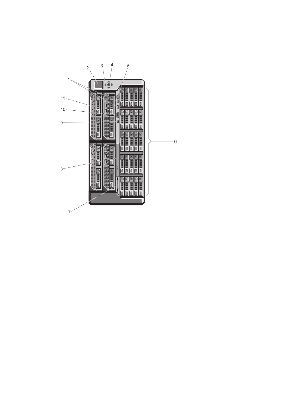
Figure 4. Front-Panel Features And Indicators—2.5 Inch Hard Drive Chassis
12
Page 13
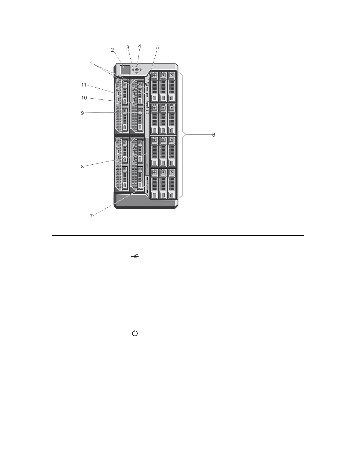
Figure 5. Front-Panel Features And Indicators—3.5 Inch Hard Drive Chassis
Item Indicator, Button, or
Icon Description
Connector
1 USB connectors (2) Allows a keyboard and mouse to be connected to
the system.
2 LCD panel Provides system information and status and error
messages to indicate when the system is operating
correctly or when the system needs attention.
3 LCD menu scroll buttons
Moves the cursor in one-step increments.
(4)
4 Selection ("check") button Selects and saves an item on the LCD screen and
moves to the next screen.
5 Enclosure power-on
indicator, power button
The power-on indicator lights when the enclosure
power is on. The power button controls the power
supply output to the system.
6 Hard drives
2.5 inch hard
drive enclosure
Up to twenty five 2.5 inch
hot-swappable hard
drives.
13
Page 14
Item Indicator, Button, or
Connector
Icon Description
3.5 inch hard
drive enclosure
7 Information tag A slide-out label panel which allows you to record
system information such as Service Tag, NIC, MAC
address, the system's electrical rating, and
Worldwide Regulatory Agency marks.
8 Optical drive (optional) One optional SATA DVD-ROM drive or DVD+/-RW
drive.
9 Vents Vents for the temperature sensor.
NOTE: To ensure proper cooling, ensure that
the vents are not blocked.
10 Video connector Allows a monitor to be connected to the system.
11 Server modules Up to four PowerEdge M520 or M620 server
modules specifically configured for the enclosure.
Up to twelve 3.5 inch hotswappable hard drives.
KVM Features
• Local KVM access can be remotely disabled on a per server module basis, using the server module’s iDRAC
interface (access is enabled by default).
• One VGA connector—The KVM supports a video display resolution range from 640 × 480 at 60 Hz up to 1280 ×
1024 × 65,000 colors (non-interlaced) at 75 Hz.
• Two USB ports for keyboard and mouse.
• The KVM provides access to the server modules. You can access one server module at a time using the LCD
panel.
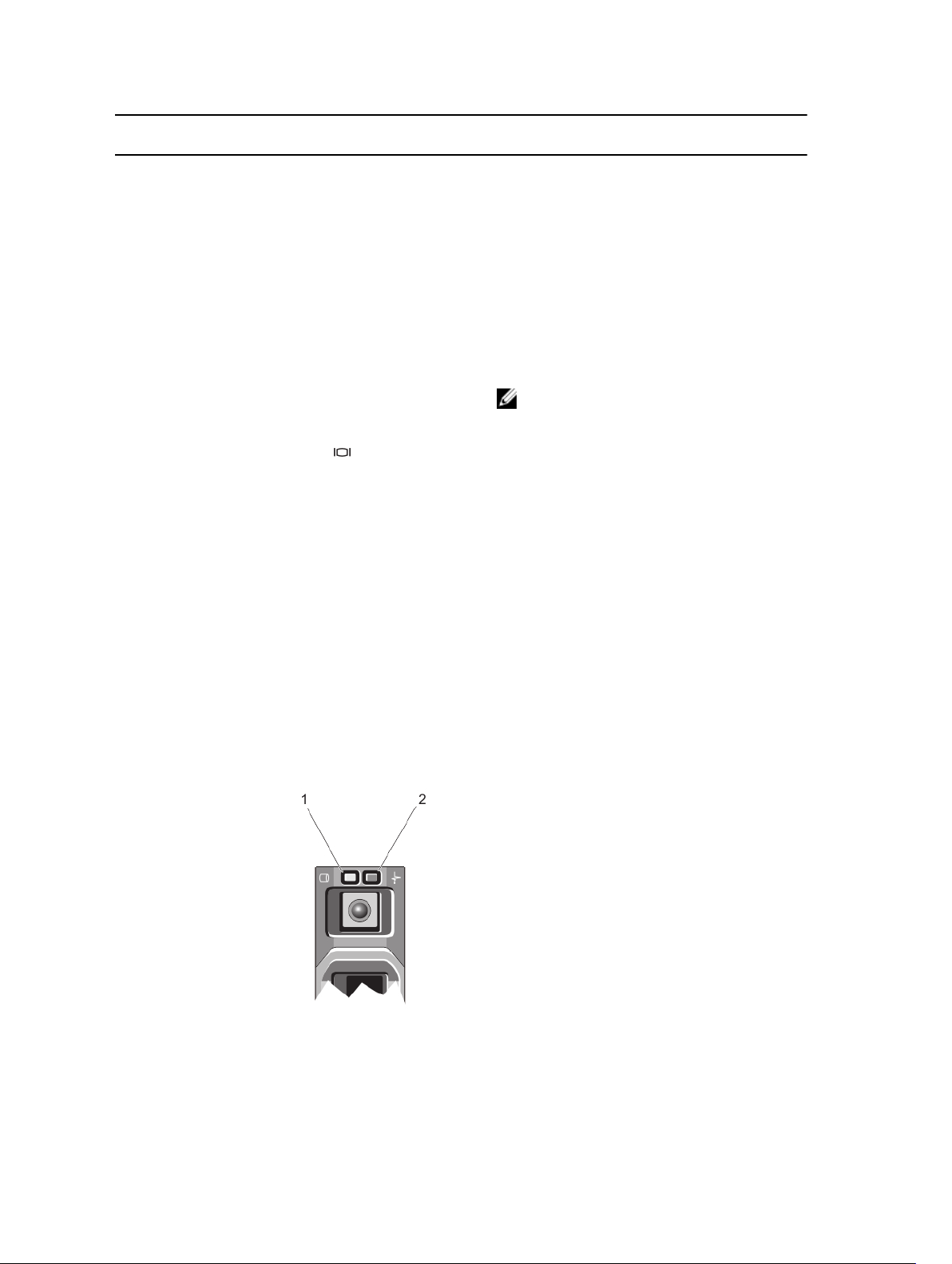
Hard-Drive Indicator Patterns
Figure 6. Hard-Drive Indicators
1. hard-drive activity indicator (green)
14
Page 15
2. hard-drive status indicator (green and amber)
Drive-Status
Indicator Pattern
Condition
Blinks green two
times per second
Off Drive ready for insertion or removal
Blinks green, amber,
and off
Blinks amber four
times per second
Blinks green slowly Drive rebuilding
Steady green Drive online
Blinks green three
seconds, amber three
seconds, and off six
seconds
Identifying drive or preparing for removal
NOTE: The drive status indicator remains off until all hard drives are initialized after the
system is turned on. Drives are not ready for insertion or removal during this time.
Predicted drive failure
Drive failed
Rebuild aborted
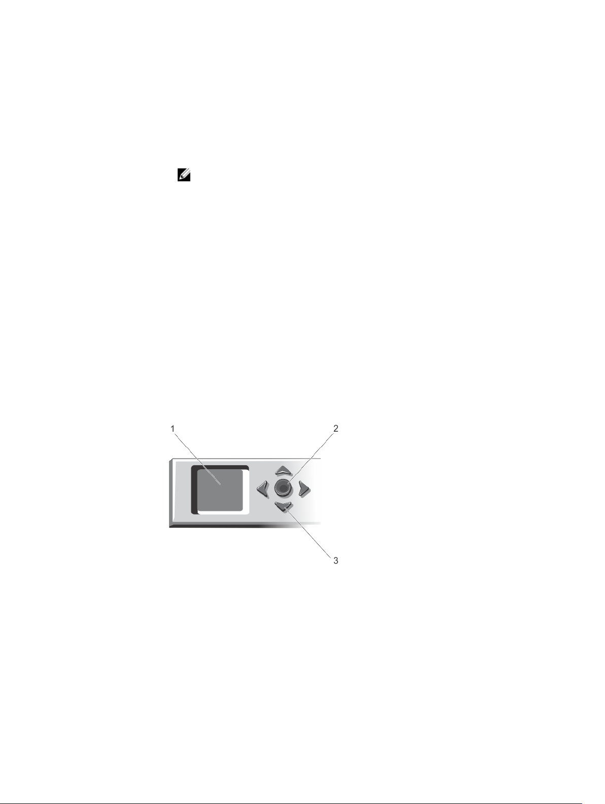
LCD Module
You can use the LCD panel on the enclosure chassis to perform configuration and diagnostics, and to obtain status
information about the chassis and its contents.
Figure 7. LCD Display
1. LCD screen
2. selection ("check") button
3. scroll buttons (4)
LCD Module Features
The primary function of the LCD module is to provide real-time information on the health and status of the modules in the
enclosure.
LCD module features include:
15
Page 16

• A deployment setup that allows you to configure the CMC’s network settings during initial system setup.
• Menus to configure the iDRAC in each server module.
• Status information screens for each server module.
• Status information screens for the modules installed in the back of the enclosure, including the I/O module,
blower modules, CMC, KVM, and power supplies.
• An IP Summary screen listing the IP addresses of all components in the system.
• Real time power consumption statistics, including high and low values, and average power consumption.
• Ambient temperature values.
• AC power information.
• Critical failure alerts and warnings.
Using The LCD Module Menus
The LCD Setup menu displays a menu of items that can be configured.
Use the up and down arrow buttons to highlight an item in the menu or highlight the Back icon if you want to return to
the Main menu.
Press the center button to activate your selection.
Key Action
Left and right arrows Move between screens
Up arrow or down
arrow
Center button Select and save an item and move to the next screen
Move to the previous or next option on a screen
Main Menu
From the Main menu, you can navigate to one of the following screens:
Screen Description
LCD Setup Contains the options such as Language Setup, LCD Orientation, and the Default Screen.
KVM Mapping Contains the options to map or unmap the KVM to the servers.
DVD Mapping Contains the option to map or unmap the DVD drive on the chassis to the servers.
Enclosure Displays status information for the chassis.
IP Summary Displays IPv4 and IPv6 information about CMC and iDRAC.
LCD Setup Menu
The LCD Setup Menu displays a menu of items that can be configured:
Language Setup Select the language you want to use for LCD screen text and messages.
LCD Orientation Select either Tower Mode or Rack Mode based on the installation orientation of the chassis.
Default Screen Select the screen (Main menu, Front Status, Rear Status, Side Status, or Custom) that is
displayed when there is no activity on the LCD panel.
Use the up and down arrow buttons to highlight an item in the menu or highlight the Back icon if you want to return to
the Main menu.
Press the center button to activate your selection.
16
Page 17

DVD Mapping
From this screen, you can view the DVD to server mapping information, map another server to the DVD drive on the
chassis, or unmap the existing connection.
KVM Mapping Menu
From this screen, you can view the KVM to server mapping information, map another server to the KVM, or unmap the
existing connection.
Enclosure Menu
From this screen, you can navigate to the following screens:
• Front Status
• Rear
• Side
• Enclosure status
Use the navigation buttons to highlight the desired item (highlight the Back icon to return to the Main menu) and press
the center button. The selected screen is displayed.
IP Summary Menu
The IP Summary screen displays the IP information for CMC (IPv4 and IPv6) and iDRAC (IPv4 and IPv6) on each of the
installed servers.
Use the up and down arrow buttons to scroll through the list. Use the left and right arrow buttons to scroll selected
messages that are longer than the screen.
Use the up and down arrow buttons to select the Back icon and press the center button to return to the Enclosure menu.
17
Page 18
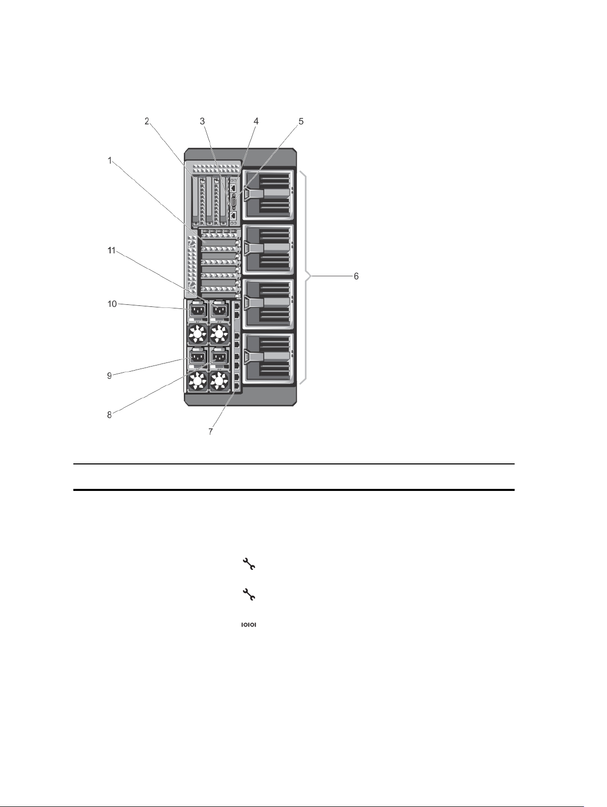
Back-Panel Features And Indicators
Figure 8. Back-Panel Features and Indicators
Item Indicator, Button, or
Connector
1 PCIe expansion card slots
low-profile (5)
2 PCIe expansion card slots
full height (3)
3 CMC GbE port 2 Connects the network cable from the management system
4 CMC GbE port 1 Connects the network cable from the management system
5 Serial connector DB-9 serial connector for CMC configuration.
6 Blower modules (4) Provide cooling for the server modules.
7 I/O module ports Network interface for I/O modules.
8 Power supply (PSU4) 1100 W AC
18
Icon Description
Allows you to connect up to five low-profile PCI Express
expansion cards.
Allows you to connect up to three full-height PCI Express
expansion cards.
to the secondary CMC.
to the primary CMC.
Page 19
Item Indicator, Button, or
Connector
9 Power supply (PSU3) 1100 W AC
10 Power supply (PSU1) 1100 W AC
11 Power supply (PSU2) 1100 W AC
Icon Description
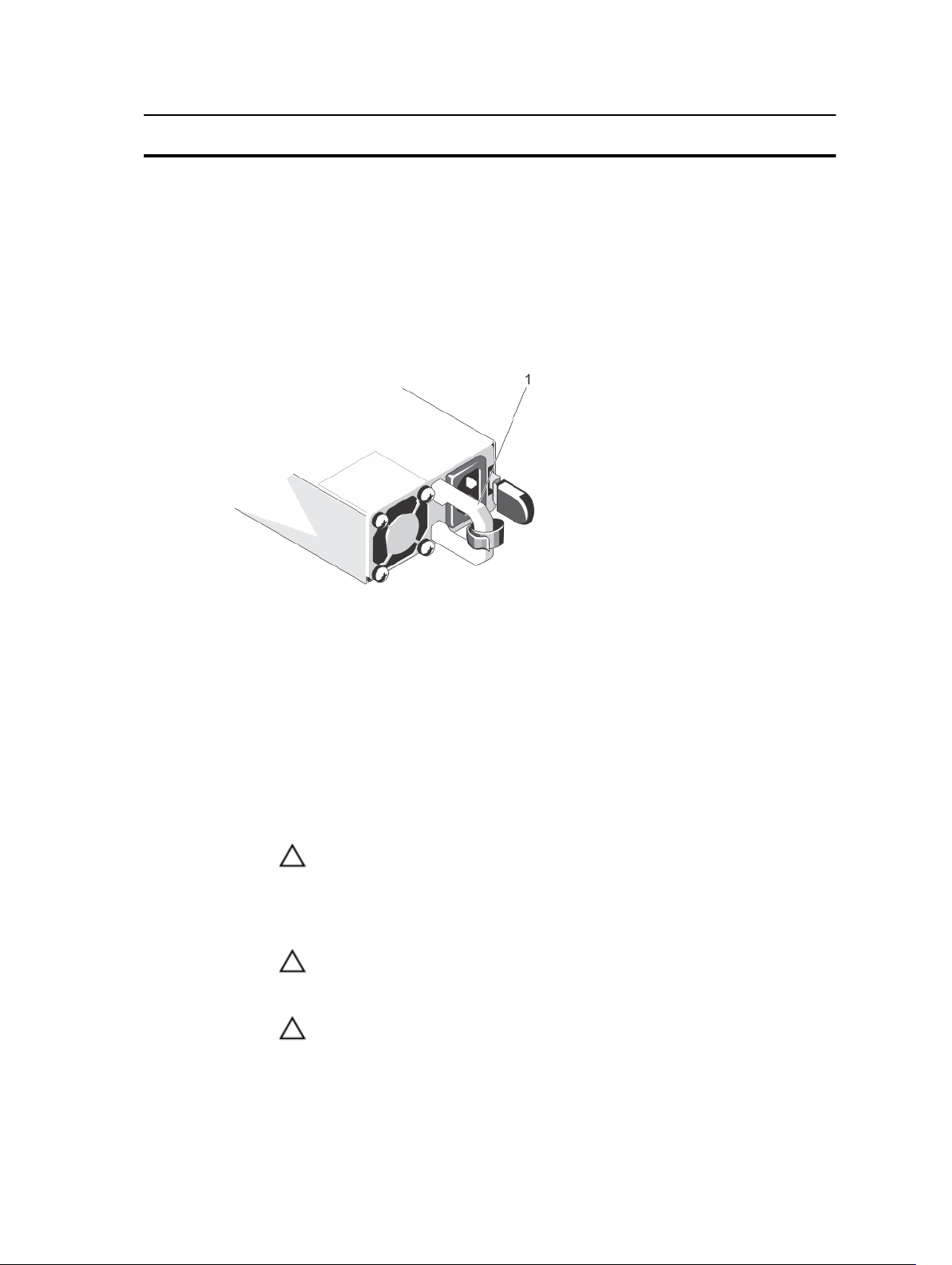
Power Supply Indicators
Each AC power supply has an illuminated translucent handle that serves as an indicator to show whether power is
present or whether a power fault has occurred. The AC power supplies must be connected to a Power Distribution Unit
(PDU) or to an electrical outlet.
Figure 9. Power Supply Indicators
1. AC power supply status indicator/handle
The power supply indicators provide the following information:
Power Indicator
Pattern
Not lit Power is not connected.
Green In standby mode, the handle lights green indicating that a valid power source is connected to
Flashing amber Indicates a problem with the power supply.
Condition
the power supply and that the power supply is operational.
CAUTION: When correcting a power supply mismatch, replace only the power supply with
the flashing indicator. Swapping the opposite power supply to make a matched pair can
result in an error condition and unexpected system shutdown. To change from a High
Output configuration to a Low Output configuration or vice versa, you must power down
the system.
CAUTION: AC Power supplies support both 220 V and 110 V input voltages. When two
identical power supplies receive different input voltages, they can output different
wattages, and trigger a mismatch.
CAUTION: All power supplies used must be of the same type and have the same maximum
output power.
19
Page 20
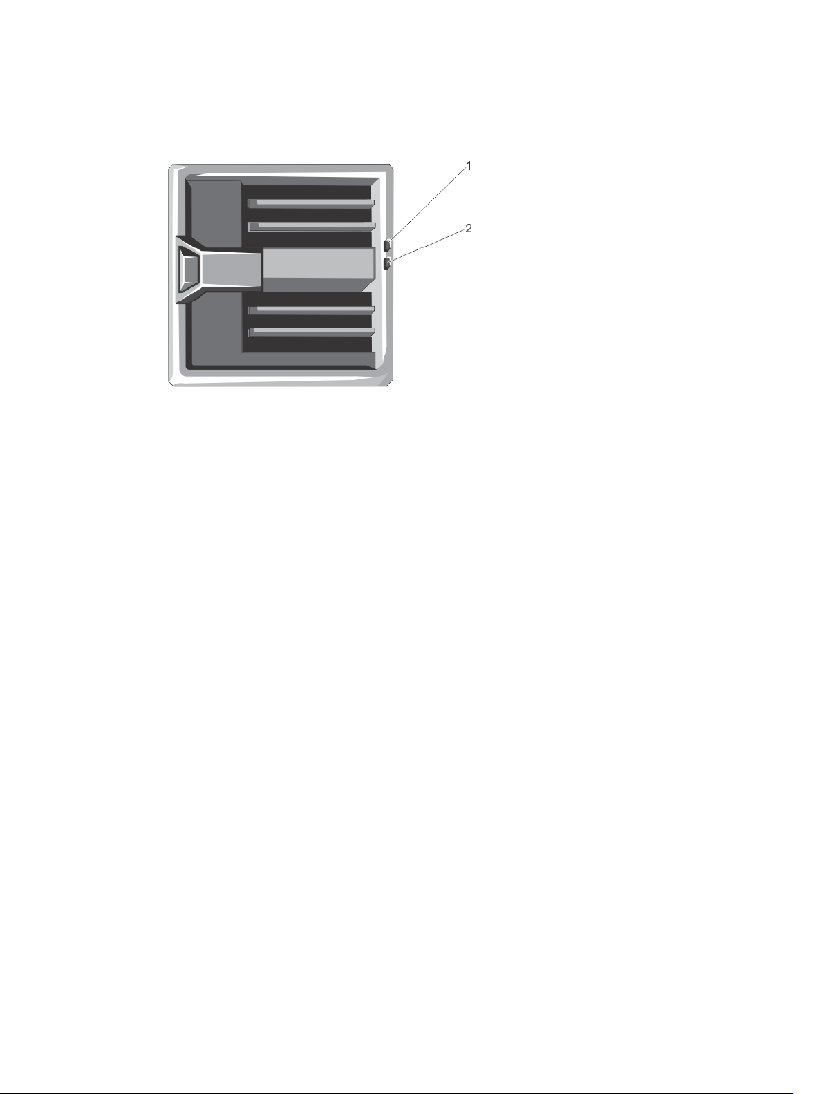
Blower Module Indicators
Figure 10. Blower Module Indicators
1. blower module fault indicator
2. blower module power indicator
The indicators provide the following information:
Indicator Description
Blower module
power indicator
Blower module fault
indicator
Steady Green The blower module is receiving power.
Off The blower module is not receiving power.
Blinking Amber The blower module is in a fault condition.
Off The blower module is operating normally.
20
Page 21
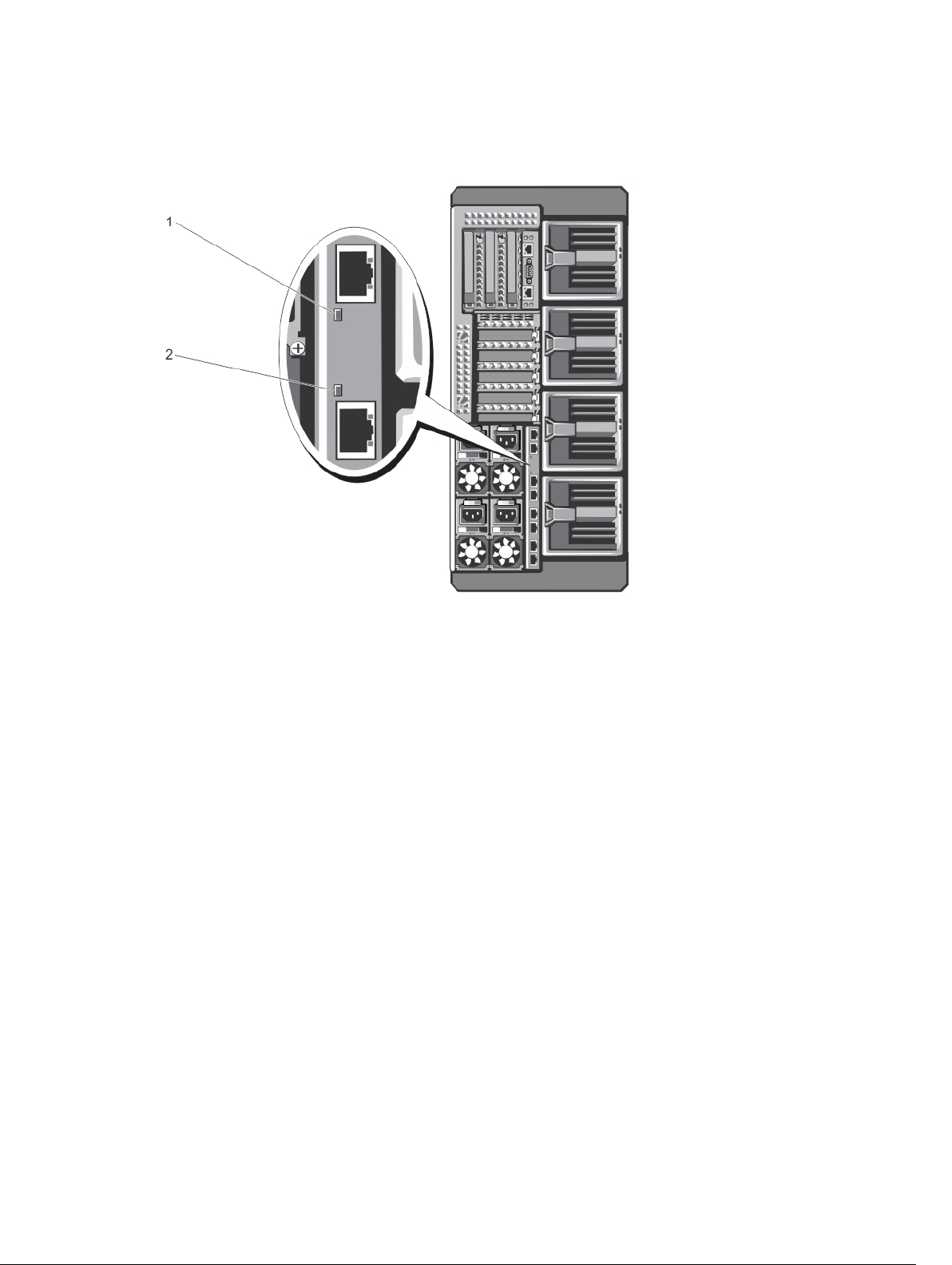
I/O Module Indicators
Figure 11. I/O Module Indicators
1. power indicator
2. status indicator
The indicators provide the following information:
Indicator Description
Power indicator
Status indicator
For more information, see the I/O module's documentation at dell.com/poweredgemanuals.
Green The I/O module is operating normally.
Off The I/O module is powered off.
Blue The I/O module is operating normally.
Blinking Blue The CMC is identifying the I/O module.
Blinking Amber The I/O module is in a fault condition.
Off The I/O module is powered off, or booting is in progress.
21
Page 22
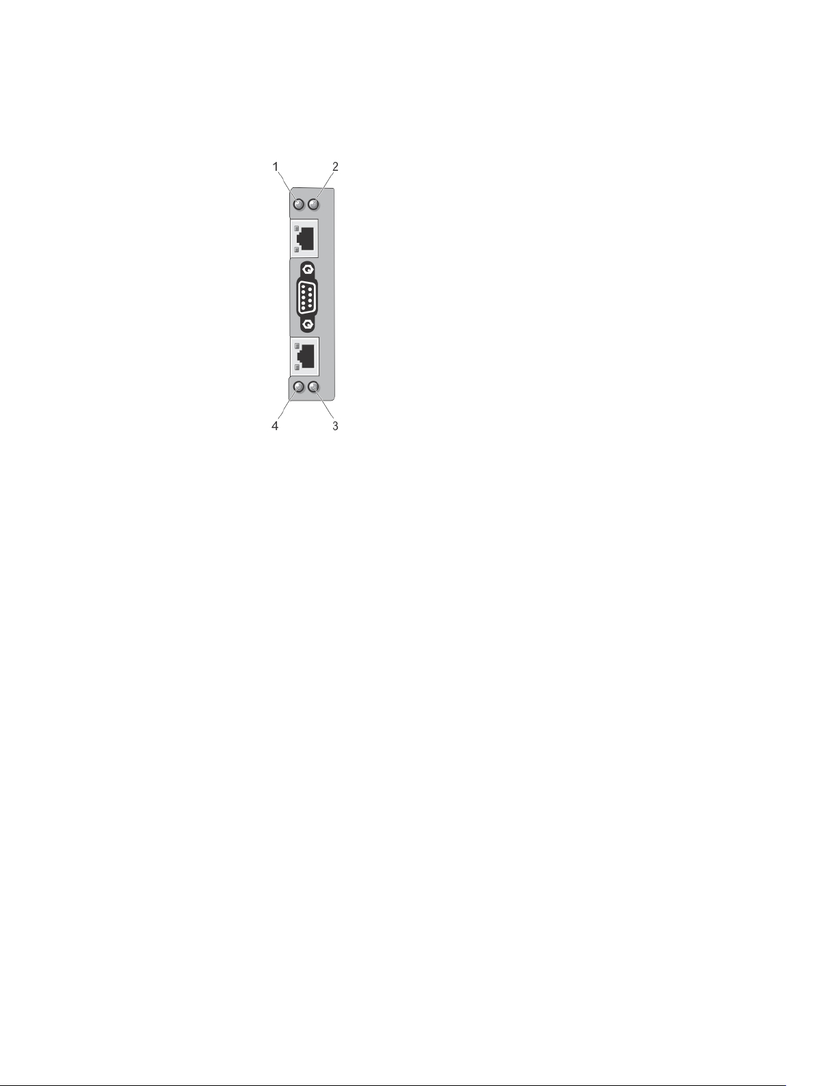
CMC Indicators
Figure 12. CMC Indicators
1. status/identification indicator (CMC 1)
2. power indicator (CMC 1)
3. power indicator (CMC 2)
4. status/identification indicator (CMC 2)
The CMC indicators on the back panel of the enclosure provide the following information:
Indicator Description
Power indicator
Status indicator
Green The CMC is receiving power.
Off The CMC is not receiving power.
Blue The CMC is active and operating normally.
Amber The CMC is in fault condition.
CMC Features
The CMC provides the following multiple systems management functions:
• Enclosure-level real-time automatic power and thermal management:
– Monitors system power requirements and supports the optional Dynamic Power Supply Engagement
(DPSE) mode. The DPSE mode improves power efficiency by allowing the CMC to dynamically place
power supplies in standby mode, depending on the load and redundancy requirements.
– Reports real-time power consumption, which includes logging high and low points with a time stamp.
22
Page 23

– Supports setting an optional enclosure Maximum Power Limit, which either alerts or takes actions, such
as throttling server modules and/or preventing the power up of new server modules to keep the
enclosure under the defined maximum power limit.
– Monitors and automatically controls cooling fans based on actual ambient and internal temperature
measurements.
– Provides comprehensive enclosure inventory and status or error reporting.
• Centralized configuration of the following:
– The enclosure's shared storage settings.
– Mapping of add-in PCIe cards to the server modules.
– The enclosure’s network and security settings.
– Power redundancy and power ceiling settings.
– I/O module and iDRAC network settings.
– First boot device on the server modules.
– Checks I/O fabric consistency for the I/O module, PCIe slots, storage subsystem, and server modules
and disables components if necessary to protect the system hardware.
– User access security.
CMC Fail-Safe Mode
The VRTX enclosure enables the fail-safe mode to protect the server modules and the I/O module from failures. The failsafe mode is enabled when no CMC is in control of the chassis. During the CMC failover period or during a single CMC
management loss:
• server modules cannot be accessed remotely
• you cannot turn on a server module(s)
• the cooling fans continue to operate at the same speed
The following are some of the conditions that can result in CMC management loss:
Condition Description
CMC removal Chassis management resumes after replacing CMC, or after failover to standby CMC.
CMC network cable
removal or network
connection loss
CMC reset Chassis management resumes after the CMC reboots or chassis fails over to the standby CMC.
CMC failover
command issued
CMC firmware update Chassis management resumes after the CMC reboots or chassis fails over to the standby CMC.
CMC error detection
and correction
NOTE
: You can configure the enclosure with a single CMC or with redundant CMCs. In redundant CMC
configurations, if the primary CMC loses communication with the enclosure or the management network, the
standby CMC takes over chassis management.
Chassis management resumes after the chassis fails over to the standby CMC. Network
failover is only enabled in redundant CMC mode.
Chassis management resumes after the chassis fails over to the standby CMC.
It is recommended that you update the standby CMC first so that there is only one failover
event. For more information on updating the CMC firmware, see the
Controller for Dell PowerEdge VRTX User’s Guide
Chassis management resumes after the CMC resets or chassis fails over to the standby CMC.
at dell.com/esmmanuals.
Dell Chassis Management
23
Page 24
Configuration Wizard
The CMC is preset for Dynamic Host Configuration Protocol (DHCP). To use a static IP address, you must toggle the CMC
setting from DHCP to a static address by either running the LCD configuration wizard, or by using a management station
and CLI commands. For more information, see the
Guide
at dell.com/esmmanuals.
To set up a network using the LCD configuration wizard:
1. If the enclosure is off, press the enclosure power button to turn it on.
The LCD screen displays a series of initialization screens as it turns on. When it is ready, the Language Setup
screen is displayed.
2. Select a language from the options in the dialog box.
The following message is displayed on the enclosure screen: Configure Enclosure?
3. Press the center button to continue to the CMC Network Settings screen.
4. Configure the CMC network settings for your network environment:
– Network speed
– Duplex mode
– Network mode (DHCP or static)
– Static IP address, subnet mask, and gateway values (if static mode was selected)
– DNS settings
5. If required, configure the iDRAC network settings.
For more information about iDRAC, see the
Dell Chassis Management Controller for Dell PowerEdge VRTX User’s
iDRAC User’s Guide
at dell.com/support/manuals.
NOTE: The configuration wizard automatically configures each server module’s iDRAC internal network
interface if you do not choose to manually configure the iDRAC settings.
NOTE: You cannot set a static IP address for the iDRAC using the LCD configuration wizard. To set a static IP
address, use the CMC web-based interface or Remote Access Controller Administrator (RACADM).
6. Review the settings on the Network Summary screen:
– If the settings are correct, press the center button to close the configuration wizard and return to the Main
Menu.
– If the settings are not correct, use the left arrow key to return to the screen for that setting and correct it.
After you complete the configuration wizard, the CMC is available on your network.
System Messages
System messages related to the server modules in the enclosure may appear on the monitor screen to notify you of a
possible problem with a server module. For a detailed listing of these error messages, including possible causes and
solutions, see the server module's documentation.
LCD Messages
For a complete list of messages that are displayed on the front panel LCD screen, see the
Controller for Dell PowerEdge VRTX User’s Guide
at dell.com/esmmanuals.
Dell Chassis Management
24
Page 25

Other Information You May Need
WARNING: See the safety and regulatory information that shipped with your system. Warranty information may be
included within this document or as a separate document.
• The
Dell PowerEdge VRTX Getting Started Guide
features, setting up your system, and technical specifications.
• The setup placemat shipped with your system provides information on the initial system setup and configuration.
• The server module's Owner's Manual provides information about the server module's features and describes
how to troubleshoot the server module and install or replace the server module's components. This document is
available online at dell.com/poweredgemanuals.
• The rack documentation included with your rack solution describes how to install your system into a rack, if
required.
• The I/O module documentation at dell.com/poweredgemanuals describes the features of the I/O module
installed in the VRTX enclosure.
• The
Dell Shared PowerEdge RAID Controller (PERC) 8 User's Guide
Shared PERC 8 card and managing the storage subsystem. This document is available online at dell.com/
storagecontrollermanuals.
• The
Dell Chassis Management Controller for Dell PowerEdge VRTX User’s Guide
installing, configuring and using the Chassis Management Controller (CMC). This document is available online at
dell.com/esmmanuals.
• The CMC
access the
• The
configuration and maintenance of the iDRAC on managed systems. This document is available online at
dell.com/esmmanuals.
• Dell systems management application documentation provides information about installing and using the
systems management software.
• For the full name of an abbreviation or acronym used in this document, see the Glossary at dell.com/support/
manuals.
• Any media that ships with your system that provides documentation and tools for configuring and managing your
system, including those pertaining to the operating system, system management software, system updates, and
system components that you purchased with your system.
• For more information on the system, scan the Quick Resource Locator (QRL) available on your system and the
system setup placemat that shipped with your system. Download the QRL application from your mobile platform
to enable the application on your mobile device.
Online Help
Online Help
provides information and instructions for the current page on the CMC web interface. To
, click Help on the CMC web interface.
Integrated Dell Remote Access Controller (iDRAC) User’s Guide
shipped with your system provides an overview of system
provides information about deploying the
provides information on
provides information about installation,
NOTE: Always check for updates on dell.com/support/manuals and read the updates first because they often
supersede information in other documents.
25
Page 26

26
Page 27
Initial System Configuration
Before You Begin
CAUTION: The enclosure power supplies must be connected to a PDU or to an electrical outlet. The power
supplies require a 100 V to 120 V or 200 V to 240 V power source. You can select only one AC power input, as the
system does not operate at both ranges simultaneously.
• Your system supports Dell PowerEdge M520 and M620 server modules that are specifically configured for the
enclosure, and can be identified by a label marked PCIe on the server module. If you install PowerEdge M520
and M620 server modules that are not configured for the enclosure, an error message is displayed. For more
information on configuring a server module for the enclosure, see Configuring A Server Module.
• Ensure that you have downloaded the latest BIOS on the server module(s) from dell.com/support.
• Update all PCIe mezzanine card firmware and iDRAC firmware on the server module(s).
• Download the latest version of CMC firmware from dell.com/support. Also, make sure that you have the
Systems Management Tools and Documentation
• If your network uses static addressing, you need the IP address, subnet mask, and gateway to configure the
CMC and other modules in the enclosure.
Initial Setup Sequence
DVD that was included with your system.
2
Dell
CAUTION: To maintain optimum thermal conditions, ensure that there are no obstructions to airflow on the front
and back of the enclosure. The front and back of the enclosure must have at least 30 cm (12 inches) and 61 cm (24
inches) of unobstructed space respectively.
• Unpack the enclosure and the server module(s) and identify each item. For more information, see the
Started Guide
• The tower system has four feet on its bottom panel that can be extended outward to help properly stabilize the
system. You can also install the optional wheel assembly. For more information, see Installing The Wheel
Assembly.
• If you are using the optional rack configuration, assemble the rails and install the system in the rack following
the safety instructions and the rack installation instructions provided with your system. For more information on
converting the system to rack mode, see Converting The System From Tower Mode To Rack Mode.
1. Install the server module(s).
CAUTION: Do not turn on the server module(s) until you have configured the I/O module.
2. Connect the network cable to the I/O module to provide network connection to the server.
NOTE: If you have a pass-through module installed in the enclosure, each server module requires its own
network cable.
and
Rack Installation Guide
WARNING: Failure to extend the system feet outward poses the risk of having the system tip over, possibly
causing bodily injury or damage to the system.
CAUTION: Rolling the system on its wheels can cause vibrations that can damage the system.
at dell.com/poweredgemanuals.
Getting
27
Page 28

3. Connect the power supply units to a PDU or electrical outlet using the power cables.
4. Optionally, connect the keyboard, video, and mouse to the enclosure.
5. Press the power button on the enclosure's front panel.
Alternatively, you can also turn on the chassis from the CMC Web interface after completing step 7.
6. Using the LCD panel on the front of the system, provide CMC with a static IP address or configure it for DHCP.
The LCD configuration wizard allows you to quickly configure the CMC and iDRAC management interfaces and
manage the enclosure remotely. You can also use a management station and the RACADM CLI to configure the
CMC.
NOTE: For a detailed description on configuring the CMC settings, see the
Controller for Dell PowerEdge VRTX User’s Guide
7. Connect to the CMC IP address through the Web browser using the default logon credentials.
The default user name is root and password is calvin.
8. Provide each iDRAC with an IP address in the CMC Web interface and enable the LAN and IPMI interface.
NOTE: iDRAC LAN interface on some server modules are disabled by default.
9. Provide the switch module with an IP address in the CMC Web interface.
NOTE: No configuration is required if you are installing a pass-through module.
10. Connect to each iDRAC through the Web browser and provide final configuration of iDRAC.
The default user name is root and password is calvin.
11. Connect to the switch module through the Web browser and provide final configuration of the switch module.
NOTE: No configuration is required if you are installing a pass-through module.
12. Turn on the server modules and install the operating system.
at dell.com/esmmanuals.
Dell Chassis Management
Logging In To The CMC
You can perform the initial network configuration of CMC before or after CMC has an IP address.
You can log in to CMC as a CMC local user, as a Microsoft Active Directory user, or as an LDAP user. You can also log in
using Single Sign-On or Smart Card.
For more information on managing the chassis and configuring the settings, see the
for Dell PowerEdge VRTX User’s Guide
at dell.com/esmmanuals.
Dell Chassis Management Controller
28
Page 29
3
Configuring Enclosure Components
Fabric A
Fabric A refers to the Ethernet connectivity provided to the server modules by the I/O module installed at the back of the
VRTX enclosure.
Fabric A provides internal connection to four lanes per server module for a maximum of 16 lanes. The maximum external
connections possible is eight RJ-45.
The following conditions apply:
• Dell PowerEdge M520 server module disables ports 3 and 4 when a pass-through module is installed. However,
if you install a switch module, all four network ports on Fabric A are utilized.
• Fabric A in PowerEdge M620 is a 10GbE capable interface, and operates at 1GbE to support a pass-through
module or a switch module.
For information on the supported I/O modules, see Supported I/O Modules.
Fabrics B And C
Fabrics B and C refer to the PCIe connections between the server modules and the VRTX enclosure. These fabrics
support PCIe mezzanine cards installed in the server modules. The enclosure has two PCIe switches (Fabric B and
Fabric C switches) integrated on the system board to connect the server modules to the Shared PoweEdge RAID
Controller (PERC) card slots and eight PCIe expansion-card slots on the enclosure.
NOTE: To locate the Shared PERC card slots and the PCIe slots on the enclosure system board, see System Board
Connectors.
The PCIe switch mapping to the PCIe card slots is dependent on the firmware and the software license installed on the
system. For more information on mapping PCIe slots, see Mapping PCIe Expansion Slots.
NOTE: PCIe NICs systems management is not supported on Fabrics B and C.
I/O Module And PCIe Mezzanine Card Configuration Guidelines
• Fabric A supports an Ethernet switch or a pass-through module.
• To enable switch configuration before imaging the server modules, the I/O module must be allowed to power-up
before the server modules are turned on.
• Each server module installed in the VRTX enclosure supports two PCIe mezzanine cards in Fabric B and Fabric C
slots. To locate the Fabric B and Fabric C slots, see the server module's Owner's Manual at dell.com/
poweredgemanuals. The PCIe mezzanine cards are mapped to the PCIe expansion slots on the enclosure. For
more information, see Mapping PCIe Expansion Slots.
NOTE: Only PCIe mezzanine cards can be installed in Fabrics B and C of the server modules. Non-PCIe
mezzanine cards such as Ethernet, Fibre Channel, or InfiniBand mezzanine cards are not supported. If you
install non-PCIe mezzanine cards on the server modules, an error message is displayed on the LCD screen
of the enclosure.
29
Page 30
NOTE: Single PCIe mezzanine card operation is not supported.
Supported I/O Modules
The enclosure supports a switch or a pass-through module. The maximum Ethernet pass-through for a pass-through
module is eight lanes. A switch module can accept upto 16 lanes from Fabric A and output up to eight lanes to the
external ports.
The following I/O modules are supported by the enclosure:
• Dell PowerEdge VRTX 1Gb R1-PT pass-through module
• Dell PowerEdge VRTX 1Gb R1-2401 switch module
NOTE: For more information on the I/O modules, see the I/O module's documentation at dell.com/
poweredgemanuals.
Configuring Network Settings For The I/O Module
You can specify the network settings for the interface used to manage the I/O module.
Before configuring the network settings for the I/O module, make sure the I/O module is turned on.
To configure the network setting, you must have Administrator privileges for Fabric A to configure the I/O module in
Group A.
You can configure the network settings using the following:
• CMC web interface
• RACADM
For more information on configuring the network settings, see the
PowerEdge VRTX User’s Guide
at dell.com/esmmanuals.
Dell Chassis Management Controller for Dell
Mapping PCIe Expansion Slots
The enclosure has two PCIe switches integrated on the system board which map the Shared PERC storage slots and
PCIe expansion slots to the PCIe mezzanine cards on the server modules.
NOTE: Before mapping or unmapping a PCIe device, the server module must be turned off.
NOTE: The PCIe switch mapping is controlled by the firmware and depends on the software license installed on the
system:
• With base licensing, each server module can be mapped to a maximum of two PCIe slots.
• With the advanced licensing, a server module can map all available PCIe slots.
• Default factory configuration has all PCIe slots unmapped.
For more information on PCIe slot configuration licensing, see the
PowerEdge VRTX User’s Guide
The switches map the mezzanine cards to the PCIe slots on the enclosure's system board. There are five PCIe low
profile slots on the system board and three full-height, full-length PCIe slots on the PCIe riser. All the PCIe slots can be
mapped to the PCIe mezzanine cards on the server modules to provide I/O expansion for the system:
PCIe mezzanine Fabric B and Fabric C cards on each server module are mapped to the PCIe switches which further map
to the PCIe slots and the Shared PERC slots on the enclosure's system board.
at dell.com/esmmanuals.
Dell Chassis Management Controller for Dell
30
Page 31

NOTE: For information on the specifications of the supported PCIe cards, see Technical Specifications.
Figure 13. Mapping PCIe Expansion Slots
Managing PCIe Slots
You can do the following using the CMC web interface:
• View the status of both individual and all PCIe slots in the chassis.
• Assign PCIe slots to server modules.
For more information on managing the PCIe slots using the CMC web interface, see the
Controller for Dell PowerEdge VRTX User’s Guide
at dell.com/esmmanuals.
Dell Chassis Management
Managing Chassis Storage
The enclosure provides shared storage with single Shared PERC/Expander configurations. The Shared PERC card
supports Single Root Input Output Virtualization (SR-IOV) feature and enables the server modules map to the local
storage through the PCIe switches on the enclosure's system board. A server module can be mapped to either a single
Virtual Disk (VD) or multiple VDs that are located on the shared storage.
For more information on the Shared PERC card, see the
dell.com/storagecontrollermanuals.
You can perform the following tasks related to the enclosure storage:
• View the status of physical disks and storage controllers
• View the properties of controllers, physical disks, virtual disks, and enclosures
• Set up controllers, physical disks, and virtual disks
• Assign virtual adapters
• Troubleshoot controller, physical disks, and virtual disks
• Update storage components
Dell Shared PowerEdge RAID Controller 8 User’s Guide
at
31
Page 32

NOTE: For information on setting up storage controllers, physical disks, and virtual disks, see the
Management Controller for PowerEdge VRTX User’s Guide
at dell.com/esmmanuals.
Dell Chassis
32
Page 33

Installing Enclosure Components
WARNING: Whenever you need to lift the system, get others to assist you. To avoid injury, do not attempt to lift the
system by yourself.
WARNING: Exercise care when removing or installing components when the system is on, to avoid the risk of
electric shock.
CAUTION: To maintain optimum thermal conditions, ensure that there are no obstructions to airflow on the front
and back of the enclosure. The front and back of the enclosure must have at least 30 cm (12 inches) and 61 cm (24
inches) of unobstructed space respectively.
NOTE: To ensure proper operation and cooling, all bays in the enclosure must be populated at all times with either
a module or with a blank.
NOTE: It is recommended that you remove the front bezel, server modules, hard drives, and power supplies from
the chassis to reduce weight, before laying the enclosure on its side.
Recommended Tools
You may need the following items to perform the procedures in this section:
• #1 and #2 Phillips screwdrivers
• T6, T8, T10, T15, and T20 Torx drivers
• Wrist grounding strap
4
Front Bezel (Optional)
Installing The Front Bezel
1. Insert the bezel tabs into the bezel tab slots in the chassis.
2. Press the top end of the bezel into the chassis until the bezel locks into place.
3. Insert the bezel key in the keylock.
4. Keeping the keylock pressed with the bezel key, rotate the keylock to the locked position.
NOTE: The bezel key can be found taped to the inside of the bezel.
33
Page 34

Figure 14. Removing and Installing the Front Bezel
1. release tab
2. keylock
3. front bezel
4. bezel tabs
Removing The Front Bezel
1. Insert the bezel key in the keylock.
2. Keeping the keylock pressed with the bezel key, rotate the keylock to the unlocked position.
3. Press the release tab at the top of the bezel toward the right.
4. Move the top end of the bezel away from the system.
5. Unhook the bezel tabs from the slots on the front of the chassis.
System Feet—Tower Mode
The system feet provide stability to the system in the tower mode.
Removing The System Feet
1. To reduce the chassis weight, remove the following (if required):
a) Front bezel (if installed)
b) Hard drives. See Removing A Hot-Swap Hard Drive.
c) Server modules. See Removing A Server Module.
d) Power supplies. See Removing A Power Supply.
2. Rotate the system feet inward.
3. Lay the enclosure on its side on a flat, stable surface with the cover release latch side on top.
4. Remove the screws securing the system feet to the system base cover.
34
Page 35

Figure 15. Removing and Installing the System Feet
1. system feet (4)
2. screws (4)
3. screw holes (4)
4. system base cover
Installing The System Feet
1. Align the screw holes on the system feet with the screw holes on the system base cover.
2. Install the screws to secure the system feet to the system base cover.
3. Place the enclosure upright on a flat, stable surface and rotate the system feet outward.
4. If removed, reinstall the hard drives, server modules, power supplies, and front bezel.
Wheel Assembly (Optional)—Tower Mode
The wheel assembly provides mobility to the system in the tower mode.
The wheel assembly consists of the following:
• Wheel assembly units (front and back)
• Power cable retention bracket
Installing The Wheel Assembly
WARNING: Whenever you need to lift the system, get others to assist you. To avoid injury, do not attempt to lift the
system by yourself.
CAUTION: Rolling the system on its wheels can cause vibrations that can damage the system.
35
Page 36

NOTE: The front and back wheel plates are labeled.
1. To reduce the chassis weight, remove the following (if required):
a) Front bezel (if installed)
b) Hard drives. See Removing A Hot-Swap Hard Drive.
c) Server modules. See Removing A Server Module.
d) Power supplies. See Removing A Power Supply.
2. Rotate the system feet inward and lay the enclosure on its side on a sturdy, stable surface with the cover release
latch side on top, and the base of the enclosure extending slightly off the surface edge.
3. Tilting the front wheel plate towards the hooks on the system base cover, align the metal stand on the wheel plate
with the hooks.
4. Insert the metal stand on the front wheel plate into the hooks until firmly seated.
5. Lower the other end of the front wheel plate to the chassis base and align the slot on the wheel plate with the tab
on the system base cover.
6. Tighten the screw on the front wheel plate to secure it to the system base cover.
7. Tilting the back wheel plate towards the hooks on the system base cover, align the metal stand on the wheel plate
with the hooks.
8. Insert the metal stand on the back wheel plate into the hooks until firmly seated.
9. Lower the other end of the back wheel plate to the chassis base and align the slot on the wheel plate with the tab
on the system base cover.
10. Tighten the screw on the back wheel plate to secure it to the system base cover.
11. Place the enclosure upright on a sturdy, stable surface.
12. If removed, reinstall the hard drives, server modules, power supplies, and front bezel.
13. Align the tabs on the power cable retention bracket with the slots on the back end of the chassis base, below the
power supply bay.
NOTE: Place the enclosure in the upright position before installing the power cable retention bracket.
14. Insert the power cable retention bracket into the slots and slide the bracket to the left to lock it.
15. Route the power supply cables through the power cable retention bracket.
36
Page 37

Figure 16. Removing and Installing the Wheel Assembly
1. hooks for the metal stands (4)
2. metal stands (2)
3. back wheel plate
4. front wheel plate
5. screws (2)
6. tabs on system base cover (4)
37
Page 38

Figure 17. Removing and Installing the Power Cable Retention Bracket
1. chassis slots
2. tabs on the power cable retention bracket (2)
3. power cable retention bracket
Removing The Wheel Assembly
1. Remove any cables routed through the power cable retention bracket.
2. Slide the power cable retention bracket to the right to unlock it.
3. Holding it by the edges, pull the bracket out of the chassis slots and away from the chassis.
4. To reduce the chassis weight, remove the following (if required):
a) Front bezel (if installed)
b) Hard drives. See Removing A Hot-Swap Hard Drive.
c) Server modules. See Removing A Server Module.
d) Power supplies. See Removing A Power Supply.
5. Lay the enclosure on a sturdy, stable surface with the cover release latch side on top, and the base of the
enclosure extending slightly off the surface edge.
38
Page 39

6. Loosen the two screws securing the front and back wheel plates to the chassis.
7. Remove the metal stands on the front and back wheel plates from the hooks on the system base cover.
8. Remove the front and back wheel plates away from the chassis base.
9. Place the enclosure upright on a sturdy, stable surface and rotate the system feet outward.
Opening And Closing The System
WARNING: Whenever you need to lift the system, get others to assist you. To avoid injury, do not attempt to lift the
system by yourself.
WARNING: Opening or removing the system cover when the system is on may expose you to a risk of electric
shock.
CAUTION: Many repairs may only be done by a certified service technician. You should only perform
troubleshooting and simple repairs as authorized in your product documentation, or as directed by the online or
telephone service and support team. Damage due to servicing that is not authorized by Dell is not covered by your
warranty. Read and follow the safety instructions that came with the product.
CAUTION: Do not operate the system without the cover for a duration exceeding five minutes.
Opening The System
CAUTION: Installing the feet on a standalone tower system is necessary to provide a stable foundation for the
system. Failure to install the feet poses the risk of having the system tip over, possibly causing damage to the
system or bodily injury.
NOTE: It is recommended that you always use a static mat and static strap while working on components in the
interior of the system.
NOTE: To replace hot-swappable components inside the enclosure, you do not need to turn off the enclosure or lay
it on its side, when opening the system.
1. If installed, remove the front bezel.
2. Turn off the server modules using the operating system commands or the CMC.
3. Turn off the enclosure and attached peripherals, and disconnect the enclosure from the electrical outlet.
4. To reduce the chassis weight, remove the following (if required):
a) Hard drives. See Removing A Hot-Swap Hard Drive.
b) Server modules. See Removing A Server Module.
c) Power supplies. See Removing A Power Supply.
5. If applicable, rotate the system feet inward and lay the system on its side on a flat stable surface, with the cover
release latch side on top.
NOTE: For systems with the wheel assembly installed, ensure that you lay the system on a sturdy surface with
the wheel assembly extending off the edge of the surface.
6. Rotate the latch release lock counter clockwise to the unlocked position.
7. Press the cover release latch and lift the cover away from the system.
39
Page 40

Figure 18. Opening and Closing the System
1. latch release lock
2. cover release latch
3. system side cover
Closing The System
1. Place the bottom edge of the cover, opposite from the cover release latch, into the slots in the system chassis.
2. Lower the cover into the chassis.
3. Press the latch end of the cover into the chassis until the latch locks into place.
4. Turn the cover latch release lock clockwise to the locked position.
5. If applicable, place the system upright on a flat, stable surface and rotate the system feet outward.
6. If removed, reinstall the hard drives, server modules, and power supplies.
7. Reconnect the enclosure to its electrical outlet and turn the enclosure on, including any attached peripherals.
8. Turn on the server modules using the operating system commands or the CMC.
9. If applicable, install the front bezel.
Inside The System
CAUTION: Many repairs may only be done by a certified service technician. You should only perform
troubleshooting and simple repairs as authorized in your product documentation, or as directed by the online or
telephone service and support team. Damage due to servicing that is not authorized by Dell is not covered by your
warranty. Read and follow the safety instructions that came with the product.
40
Page 41

NOTE: Components that are hot-swappable are marked orange and touch points on the components are marked
blue.
Figure 19. Inside the System
1. cooling fans (6)
2. cooling shroud
3. CMC card indicators (2)
4. chassis intrusion switch
5. PCIe cage
6. CMC cards (2)
7. low profile expansion-card divider unit
8. power distribution board bracket
9. system base cover
10. hard drives (25)
11. optical drive
12. server modules
13. control panel
14. mounting ears (2)
15. hard-drive backplane
Hard Drives
• The 3.5 inch hard-drive enclosure supports up to twelve hot-swappable 3.5 inch hard drives.
• The 2.5 inch hard-drive enclosure supports up to twenty-five hot-swappable 2.5 inch hard drives.
• All hard drives connect to the system board through the hard-drive backplane.
• Hard drives are supplied in hot-swappable hard-drive carriers that fit in the hard-drive slots.
• Use only hard drives that have been tested and approved for use with the hard-drive backplane.
When you format a hard drive, allow enough time for the formatting to be completed. Be aware that high-capacity hard
drives can take a number of hours to format.
41
Page 42

NOTE: The following procedures apply to the hard drives in the enclosure. For server module-specific hard drives,
see the server module's Owner's Manual at dell.com/poweredgemanuals.
Removing A 2.5 Inch Hard-Drive Blank
CAUTION: To maintain proper system cooling, all empty hard-drive slots must have hard-drive blanks installed.
1. If installed, remove the front bezel.
2. Press the release button and slide the hard-drive blank out until it is free of the hard-drive slot.
Figure 20. Removing and Installing a 2.5 Inch Hard-Drive Blank
1. hard-drive blank
2. release button
Installing A 2.5 Inch Hard-Drive Blank
1. If installed, remove the front bezel.
2. Insert the hard-drive blank into the hard-drive slot until the release button clicks into place.
3. If applicable, install the front bezel.
Removing A 3.5 Inch Hard-Drive Blank
CAUTION: To maintain proper system cooling, all empty hard-drive slots must have drive blanks installed.
1. If installed, remove the front bezel.
2. Grasp the front of the hard-drive blank, press the release button and slide the blank out until it is free of the harddrive slot.
42
Page 43

Figure 21. Removing and Installing a 3.5 Inch Hard-Drive Blank
1. hard-drive blank
2. release button
Installing A 3.5 Inch Hard-Drive Blank
1. If installed, remove the front bezel.
2. Insert the hard-drive blank into the hard-drive slot until the release button clicks into place.
3. If applicable, install the front bezel.
Removing A Hot-Swap Hard Drive
CAUTION: Before attempting to remove or install a hard drive while the system is running, see the documentation
for the storage controller card to ensure that the host adapter is configured correctly to support hot-swap hard
drive removal and insertion.
CAUTION: Do not turn off or reboot your system while the hard drive is being formatted. Doing so can cause a hard
drive failure.
CAUTION: To prevent data loss, ensure that your operating system supports hot-swap drive installation. See the
documentation supplied with your operating system.
1. If installed, remove the front bezel.
2. From the management software, prepare the hard drive for removal. Wait until the indicators on the hard-drive
carrier signal that the hard drive can be removed safely. For more information, see the documentation for the
storage controller.
If the hard drive is online, the green activity/fault indicator flashes as the drive is turned off. When the hard-drive
indicators are off, the hard drive is ready for removal.
3. Press the release button to open the hard-drive carrier release handle.
4. Slide the hard-drive carrier out until it is free of the hard-drive slot.
CAUTION: To maintain proper system cooling, all empty hard-drive slots must have hard-drive blanks
installed.
5. Insert a hard-drive blank in the empty hard-drive slot.
43
Page 44

Figure 22. Removing and Installing a Hot-Swap Hard Drive
1. release button
2. hard drive
3. hard-drive carrier handle
Installing A Hot-Swap Hard Drive
CAUTION: Many repairs may only be done by a certified service technician. You should only perform
troubleshooting and simple repairs as authorized in your product documentation, or as directed by the online or
telephone service and support team. Damage due to servicing that is not authorized by Dell is not covered by your
warranty. Read and follow the safety instructions that came with the product.
CAUTION: Use only hard drives that have been tested and approved for use with the hard-drive backplane.
CAUTION: When installing a hard drive, ensure that the adjacent drives are installed properly. Inserting a harddrive carrier and attempting to lock its handle next to a partially installed carrier can damage the partially installed
carrier's shield spring and make it unusable.
CAUTION: To prevent data loss, ensure that your operating system supports hot-swap drive installation. See the
documentation supplied with your operating system.
CAUTION: When a replacement hot-swappable hard drive is installed and the system is powered on, the hard drive
automatically begins to rebuild. Make absolutely sure that the replacement hard drive is blank or contains data that
you wish to have over-written. Any data on the replacement hard drive is immediately lost after the hard drive is
installed.
1. If installed, remove the front bezel.
2. If a hard-drive blank is installed in the hard-drive slot, remove it.
3. Install a hard drive in the hard-drive carrier.
4. Press the release button on the front of the hard-drive carrier and open the hard-drive carrier handle.
5. Insert the hard-drive carrier into the hard-drive slot until the carrier connects with the backplane.
6. Close the hard-drive carrier handle to lock the hard drive in place.
7. If applicable, install the front bezel.
44
Page 45

Removing A Hard Drive From A Hard-Drive Carrier
1. Remove the screws from the slide rails on the hard-drive carrier.
For the 2.5 inch hard drive, turn the hard-drive carrier upside down, and remove the screws from the side rails on
the hard-drive carrier.
2. Lift the hard drive out of the hard-drive carrier.
Figure 23. Removing and Installing a 2.5 Inch Hard Drive Into a Hard-Drive Carrier
1. hard-drive carrier
2. hard drive
3. screws (4)
45
Page 46

Figure 24. Removing and Installing a 3.5 Inch Hard Drive Into a Hard-Drive Carrier
1. hard-drive carrier
2. hard drive
3. screws (4)
Installing A Hard Drive Into A Hard-Drive Carrier
CAUTION: Many repairs may only be done by a certified service technician. You should only perform
troubleshooting and simple repairs as authorized in your product documentation, or as directed by the online or
telephone service and support team. Damage due to servicing that is not authorized by Dell is not covered by your
warranty. Read and follow the safety instructions that came with the product.
1. Insert the hard drive into the hard-drive carrier with the connector end of the hard drive toward the back.
2. Align the screw holes on the hard drive with the back set of holes on the hard-drive carrier.
When aligned correctly, the back of the hard drive will be flush with the back of the hard-drive carrier.
3. Attach the screws to secure the hard drive to the hard-drive carrier.
Server Modules
NOTE: Your system supports Dell PowerEdge M520 and M620 server modules that are specifically configured for
the enclosure, and can be identified by a label marked PCIe on the server module. If you install PowerEdge M520
and M620 server modules that are not configured for the enclosure, an error message is displayed. For more
information on configuring a server module for the enclosure, see Configuring A Server Module.
NOTE: Ensure that you have downloaded the latest BIOS on the server module(s) from dell.com/support.
46
Page 47

Removing A Server Module
1. If installed, remove the front bezel.
2. Turn off the server module using the operating system commands or the CMC.
When a server module is powered off, its front-panel power indicator is off.
3. Press the release button on the server module handle.
4. Pull out the server module handle to unlock the server module from the enclosure.
CAUTION: If you are permanently removing the server module, install a server module blank(s). Operating the
system for an extended period of time without a server module blank installed can cause the enclosure to
overheat.
5. Slide the server module out of the enclosure.
CAUTION: To protect the I/O connector pins, install the I/O connector covers every time a server module is
removed from the enclosure.
6. Install the I/O connector cover over the I/O connector.
Figure 25. Removing and Installing the I/O Connector Cover
1. I/O connector cover
47
Page 48

Figure 26. Removing and Installing a Server Module
1. release button
2. PCIe label on server module
NOTE: This label indicates that the
server module is configured specifically
for the VRTX enclosure.
3. guide rail on server module (or server module
blank)
4. guide rail on enclosure
5. server module handle
Configuring A Server Module
NOTE: Follow this procedure to install PowerEdge M520 or M620 server modules that are not configured for the
VRTX enclosure.
NOTE: If you install PowerEdge M520 or M620 server modules that are not configured for the VRTX enclosure, an
error message is displayed.
To configure a server module for the VRTX enclosure:
1. Open the server module.
For more information on opening a server module, see the server module's Owner's Manual at dell.com/
poweredgemanuals.
2. Remove any mezzanine cards installed in Fabric B and Fabric C slots of the server module.
3. Install PCIe Mezzanine cards in the vacant Fabric B and Fabric C slots.
For more information on installing the PCIe Mezzanine cards, see the server module's Owner's Manual at dell.com/
poweredgemanuals.
48
Page 49

4. Ensure that no tools or parts are left inside the server module.
5. Slide the cover on the server module until it clicks into position.
A properly seated cover is flush with the surface of the server module chassis.
6. Install the latest iDRAC Enterprise license. For more information, see
manuals.
iDRAC7 User's Guide
, at dell.com/support/
Installing A Server Module
Your system supports Dell PowerEdge M520 and M620 server modules that are specifically configured for the VRTX
enclosure, and can be identified by a label marked PCIe on the top of the server module.
1. If you are installing a new server module, remove the plastic cover from the I/O connector(s) and save for future
use.
2. If applicable, configure the server module. For more information, see Configuring A Server Module.
3. Orient the server module so that the module handle is on the left side of the server module.
4. Align the server module with the server module slot and guide rails on the enclosure.
5. Using both hands, slide the server module into the enclosure until the module release handle engages and locks
the server module in place.
6. If applicable, reinstall the front bezel.
Power Supplies
Your system supports up to four 1100 W AC power supplies in 1+1, 2+1, 3+1, and 2+2 redundant configurations.
NOTE: All power supplies must be of the same type and have the same maximum output power.
NOTE: In the 2+2 redundant configuration, PSU1 and PSU2 are connected to one grid, and PSU3 and PSU4 are
connected to another grid.
Power Supply Blanks
If the enclosure is operated with less than four power supplies, power supply blanks must be installed in the unoccupied
power supply bays to maintain proper cooling airflow in the enclosure.
To remove the power supply blank in the bay, pull outward on the blank.
49
Page 50

Figure 27. Removing and Installing a Power Supply Blank
1. power supply blank
To install the power supply blank, align the blank with the power supply bay and insert it into the chassis until it clicks
into place.
Removing A Power Supply
CAUTION: Many repairs may only be done by a certified service technician. You should only perform
troubleshooting and simple repairs as authorized in your product documentation, or as directed by the online or
telephone service and support team. Damage due to servicing that is not authorized by Dell is not covered by your
warranty. Read and follow the safety instructions that came with the product.
NOTE: The power supplies are hot-swappable. Remove and replace only one power supply at a time in a system
that is turned on.
NOTE: In systems that ship with the wheel assembly, a power cable retention bracket is used to route the power
cable from the power supply.
1. Disconnect the power cable from the power source and the power supply you intend to remove.
a) In systems without the wheel assembly installed, remove the power cable from the cable strap.
b) In systems with the wheel assembly installed, remove the power cable from the power cable retention bracket
slot.
2. Press the release latch and slide the power supply out of the chassis.
50
Page 51

Figure 28. Removing and Installing a Power Supply
1. connector
2. power supply
3. power supply handle
4. release latch
Figure 29. Securing the Power Cable (Without Wheel Assembly)
51
Page 52

1. power cable
2. strap
Figure 30. Securing the Power Cable (With Wheel Assembly)
1. power cable
2. power cable retention bracket
Installing A Power Supply
CAUTION: Many repairs may only be done by a certified service technician. You should only perform
troubleshooting and simple repairs as authorized in your product documentation, or as directed by the online or
telephone service and support team. Damage due to servicing that is not authorized by Dell is not covered by your
warranty. Read and follow the safety instructions that came with the product.
1. If applicable, remove the power supply blank.
2. Slide the new power supply into the enclosure until the power supply is fully seated and the release latch snaps
into place.
3. Connect the power cable to the power supply and plug the cable into a power outlet.
a) In systems without the wheel assembly installed, secure the power cable with the strap.
b) In systems with the wheel assembly installed, route the power cable from the power supply through the power
cable retention bracket, by sliding it into one of the slots on the bracket.
52
Page 53

NOTE: When installing, hot-swapping, or hot-adding a new power supply, allow several seconds for the
system to recognize the power supply and determine its status. The power supply status indicator turns green
to indicate that the power supply is functioning properly.
Cooling Shroud
Removing The Cooling Shroud
CAUTION: Many repairs may only be done by a certified service technician. You should only perform
troubleshooting and simple repairs as authorized in your product documentation, or as directed by the online or
telephone service and support team. Damage due to servicing that is not authorized by Dell is not covered by your
warranty. Read and follow the safety instructions that came with the product.
CAUTION: Never operate your system with the cooling shroud removed. The system may get overheated quickly,
resulting in shutdown of the system and loss of data.
1. If installed, remove the front bezel.
2. Turn off the server modules using the operating system commands or the CMC.
3. Turn off the enclosure, including any attached peripherals, and disconnect the enclosure from the electrical outlet
and peripherals.
4. To reduce the chassis weight, remove the following (if required):
a) hard drives
b) server modules
c) power supplies
5. If applicable, rotate the system feet inward and lay the system on its side on a flat stable surface, with the cover
release latch side on top.
6. Open the system.
7. Holding it by the edges, disengage the shroud from the release pins on the hard-drive backplane, and lift the shroud
away from the system.
53
Page 54

Figure 31. Removing and Installing the Cooling Shroud
1. release pins on the hard-drive backplane (2)
2. cooling shroud
3. pin on the cooling fan assembly
Installing The Cooling Shroud
CAUTION: Many repairs may only be done by a certified service technician. You should only perform
troubleshooting and simple repairs as authorized in your product documentation, or as directed by the online or
telephone service and support team. Damage due to servicing that is not authorized by Dell is not covered by your
warranty. Read and follow the safety instructions that came with the product.
1. Align the slot on the cooling shroud with the pin on the cooling fan assembly.
When aligned, the slots on the other edge of the shroud align with the release pins on the hard-drive backplane.
2. Lower the cooling shroud into the chassis.
3. Press down the shroud over the release pins on the hard-drive backplane, until it is firmly seated.
4. Close the system.
5. If applicable, place the system upright on a flat, stable surface and rotate the system feet outward.
6. If removed, reinstall the hard drives, server modules, and power supplies.
7. Reconnect the enclosure to its electrical outlet and turn the enclosure on, including any attached peripherals.
8. Turn on the server modules using the operating system commands or the CMC.
9. If applicable, install the front bezel.
54
Page 55

Cooling Fans
Your system supports six hot-swappable cooling fans that provide cooling to the storage and I/O components in the
enclosure.
To provide increased cooling to the storage and PCIe components in the chassis, you can set the fan configuration to
Fan Offset in the CMC web interface.
For more information on the Fan Offset option, see “Advanced Fan Configuration” in the CMC
NOTE: In the event of a problem with a particular fan, the fan number is referenced by the system’s management
software, allowing you to easily identify and replace the appropriate fan by noting the fan numbers on the cooling
fan assembly.
Removing A Cooling Fan
WARNING: Opening or removing the system cover when the system is on may expose you to a risk of electric
shock. Exercise utmost care while removing or installing cooling fans.
WARNING: The cooling fan can continue to spin for some time after it has been powered down. Allow time for the
fan to stop spinning before removing it from the system.
CAUTION: Many repairs may only be done by a certified service technician. You should only perform
troubleshooting and simple repairs as authorized in your product documentation, or as directed by the online or
telephone service and support team. Damage due to servicing that is not authorized by Dell is not covered by your
warranty. Read and follow the safety instructions that came with the product.
CAUTION: To maintain optimum thermal conditions, ensure that there are no obstructions to airflow on the front
and back of the enclosure. The front and back of the enclosure must have at least 30 cm (12 inches) and 61 cm (24
inches) of unobstructed space respectively.
Online Help
.
CAUTION: The cooling fans are hot-swappable. To maintain proper cooling while the system is on, replace only
one fan at a time.
NOTE: The procedure for removing each fan is identical.
1. Open the system.
2. Press the fan release tab and lift the cooling fan out of the cooling-fan assembly.
55
Page 56

Figure 32. Removing and Installing a Cooling Fan
1. cooling-fan assembly
2. fan release tab
3. cooling fans (6)
4. cooling-fan connectors (6)
Installing A Cooling Fan
CAUTION: Many repairs may only be done by a certified service technician. You should only perform
troubleshooting and simple repairs as authorized in your product documentation, or as directed by the online or
telephone service and support team. Damage due to servicing that is not authorized by Dell is not covered by your
warranty. Read and follow the safety instructions that came with the product.
1. Align the plug at the base of the cooling fan with the connector on the system board.
2. Slide the cooling fan into the securing slots until the tabs lock into place.
3. Close the system.
Cooling-Fan Assembly
Removing The Cooling-Fan Assembly
CAUTION: Many repairs may only be done by a certified service technician. You should only perform
troubleshooting and simple repairs as authorized in your product documentation, or as directed by the online or
telephone service and support team. Damage due to servicing that is not authorized by Dell is not covered by your
warranty. Read and follow the safety instructions that came with the product.
1. If installed, remove the front bezel.
2. Turn off the server modules using the operating system commands or the CMC.
3. Turn off the enclosure, including any attached peripherals, and disconnect the enclosure from the electrical outlet
and peripherals.
56
Page 57

4. To reduce the chassis weight, remove the following (if required):
a) hard drives
b) server modules
c) power supplies
5. If applicable, rotate the system feet inward and lay the system on its side on a flat stable surface, with the cover
release latch side on top.
6. Open the system.
7. Remove the cooling shroud.
8. Unlock the cooling-fan assembly from the chassis by rotating the release levers upward.
9. Lift the cooling-fan assembly out of the chassis.
Figure 33. Removing and Installing the Cooling-Fan Assembly
release levers (2)
1.
2. cooling-fan assembly
3. cooling fans (6)
4. cooling-fan connectors (6)
5. support brackets (2)
57
Page 58

Installing The Cooling-Fan Assembly
CAUTION: Many repairs may only be done by a certified service technician. You should only perform
troubleshooting and simple repairs as authorized in your product documentation, or as directed by the online or
telephone service and support team. Damage due to servicing that is not authorized by Dell is not covered by your
warranty. Read and follow the safety instructions that came with the product.
1. Align the cooling-fan assembly with the support brackets on the sides of the chassis, and the guide pin on the
chassis base.
2. Slide the cooling-fan assembly into the chassis.
3. Lock the cooling-fan assembly into the chassis by rotating the blue release levers downward until firmly seated.
4. Reinstall the cooling shroud.
5. Close the system.
6. If applicable, place the system upright on a flat, stable surface and rotate the system feet outward.
7. If removed, reinstall the hard drives, server modules, and power supplies.
8. Reconnect the enclosure to its electrical outlet and turn the enclosure on, including any attached peripherals.
9. Turn on the server modules using the operating system commands or the CMC.
10. If applicable, install the front bezel.
Blower Modules
Your system supports four hot-swappable blower modules to ensure proper cooling of the server modules.
To provide increased cooling for the server modules in the enclosure, you can set the blower configuration to the
Enhanced Cooling Mode in the CMC web interface. For more information on the Enhanced Cooling Mode option, see
“Advanced Fan Configuration” in the CMC
Online Help
.
Removing A Blower Module
WARNING: Do not operate the system without the blower modules.
CAUTION: While replacing a blower module when the enclosure is on, ensure that you install the replacement
blower module within 30 seconds to prevent cooling problems.
CAUTION: Exercise care while handling the blower module to prevent damage to the connector on the blower
module.
CAUTION: Many repairs may only be done by a certified service technician. You should only perform
troubleshooting and simple repairs as authorized in your product documentation, or as directed by the online or
telephone service and support team. Damage due to servicing that is not authorized by Dell is not covered by your
warranty. Read and follow the safety instructions that came with the product.
CAUTION: The blower closeout door is spring loaded. To prevent injury, exercise care when placing your hand or
fingers inside the blower module bay.
58
Page 59

CAUTION: To maintain optimum thermal conditions, ensure that there are no obstructions to airflow on the front
and back of the enclosure. The front and back of the enclosure must have at least 30 cm (12 inches) and 61 cm (24
inches) of unobstructed space respectively.
1. Identify the failed blower module using the back-panel blower module indicators.
2. Press the release tab on the blower module handle and slide the blower module out of the chassis.
Figure 34. Removing and Installing a Blower Module
1. blower module
2. release tab
Installing A Blower Module
CAUTION: Many repairs may only be done by a certified service technician. You should only perform
troubleshooting and simple repairs as authorized in your product documentation, or as directed by the online or
telephone service and support team. Damage due to servicing that is not authorized by Dell is not covered by your
warranty. Read and follow the safety instructions that came with the product.
CAUTION: Exercise care while handling the blower module to prevent damage to the connector on the blower
module.
CAUTION: The blower closeout door is spring loaded. To prevent injury, exercise care when placing your hand or
fingers inside the blower module bay.
CAUTION: When replacing a blower module when the enclosure is on, install the replacement blower module
within 30 seconds to prevent server module cooling problems.
1. Align the blower module with the slot on the chassis.
2. Holding the blower module by its handle, slide it into the chassis until it clicks into the slot and is fully seated.
59
Page 60

Removing The Blower Module Bay
CAUTION: Many repairs may only be done by a certified service technician. You should only perform
troubleshooting and simple repairs as authorized in your product documentation, or as directed by the online or
telephone service and support team. Damage due to servicing that is not authorized by Dell is not covered by your
warranty. Read and follow the safety instructions that came with the product.
CAUTION: The blower closeout door is spring loaded. To prevent injury, exercise care when placing your hand or
fingers inside the blower module bay.
1. If installed, remove the front bezel.
2. Turn off the server modules using the operating system commands or the CMC.
3. Turn off the enclosure, including any attached peripherals, and disconnect the enclosure from the electrical outlet
and peripherals.
4. Remove the four blower modules.
5. Loosen the four screws securing the blower module bay to the chassis.
6. Pull the blower module bay out of the chassis.
Figure 35. Removing and Installing the Blower Module Bay
1. blower module bay
2. screws (4)
Installing The Blower Module Bay
CAUTION: Many repairs may only be done by a certified service technician. You should only perform
troubleshooting and simple repairs as authorized in your product documentation, or as directed by the online or
telephone service and support team. Damage due to servicing that is not authorized by Dell is not covered by your
warranty. Read and follow the safety instructions that came with the product.
60
Page 61

CAUTION: The blower closeout door is spring loaded. To prevent injury, exercise care when placing your hand or
fingers inside the blower module bay.
1. Align the blower module bay with the slot on the back of the enclosure, and slide it in until it aligns with the screw
holes on the chassis and is firmly seated.
2. Tighten the four screws to secure the blower module bay to the chassis.
3. Reinstall the blower modules.
4. Reconnect the enclosure to its electrical outlet and turn the enclosure on, including any attached peripherals.
5. Turn on the server modules using the operating system commands or the CMC.
6. If applicable, install the front bezel.
I/O Module
Removing The I/O Module
CAUTION: Many repairs may only be done by a certified service technician. You should only perform
troubleshooting and simple repairs as authorized in your product documentation, or as directed by the online or
telephone service and support team. Damage due to servicing that is not authorized by Dell is not covered by your
warranty. Read and follow the safety instructions that came with the product.
1. Disconnect the cables attached to the I/O module.
2. Loosen the retention screw securing the I/O module to the chassis.
The I/O module connector disengages from the connector on the midplane.
3. Slide the I/O module out of the enclosure.
Figure 36. Removing and Installing the I/O Module
1. retention screw
2. I/O module
61
Page 62

Installing The I/O Module
CAUTION: Many repairs may only be done by a certified service technician. You should only perform
troubleshooting and simple repairs as authorized in your product documentation, or as directed by the online or
telephone service and support team. Damage due to servicing that is not authorized by Dell is not covered by your
warranty. Read and follow the safety instructions that came with the product.
1. Unpack the I/O module and prepare it for installation.
For instructions, see the documentation that accompanied the I/O module.
2. Remove the I/O connector cover.
3. Align the I/O module connector with the midplane connector, and slide the module in.
NOTE: The I/O module is not firmly seated at this stage.
CAUTION: Do not overtighten the retention screw when installing the I/O module. To prevent over-tightening,
tighten the retention screw until resistance is felt and the screw is seated. The screw tension can range from
5 in-lb to 8 in-lb (5.7 kg-cm to 9.2 kg-cm).
4. Tighten the retention screw until the I/O module connector engages with the connector on the midplane, and the
I/O module is firmly seated.
5. Connect all cables that must be attached to the I/O module.
See the documentation of the I/O module for information about its cable connections.
Optical Drive (Optional)
Removing The Optical Drive
CAUTION: Many repairs may only be done by a certified service technician. You should only perform
troubleshooting and simple repairs as authorized in your product documentation, or as directed by the online or
telephone service and support team. Damage due to servicing that is not authorized by Dell is not covered by your
warranty. Read and follow the safety instructions that came with the product.
1. If installed, remove the front bezel.
2. Turn off the server modules using the operating system commands or the CMC.
3. Turn off the enclosure, including any attached peripherals, and disconnect the enclosure from the electrical outlet
and peripherals.
4. To reduce the chassis weight, remove the following (if required):
a) hard drives
b) server modules
c) power supplies
5. If applicable, rotate the system feet inward and lay the system on its side on a flat stable surface, with the cover
release latch side on top.
6. Open the system.
7. Remove the cooling shroud.
8. Remove the cooling-fan assembly.
9. Remove the SAS cables and the backplane expander board. See Removing The Backplane Expander Board.
For the 3.5 inch hard-drive chassis, remove the hard drives and the hard-drive backplane. See Removing The Hard-
Drive Backplane.
62
Page 63

10. Disconnect the power/data cable from the system board.
11. Disconnect the power/data cable from the back of the optical drive.
Note the routing of the power/data cable as you remove them from the system board and the optical drive. You
must route these cables properly when you replace them to prevent them from being pinched or crimped.
12. To release the optical drive, press and push the release tab toward the front of the enclosure.
13. Slide the optical drive out of the enclosure until it is free of the optical-drive slot.
14. If you are not adding a new optical drive, install the optical-drive blank.
15. Reinstall the backplane expander board and connect the SAS cables. See Installing The Backplane Expander
Board.
For the 3.5 inch hard-drive chassis, reinstall the hard-drive backplane. See Installing The Hard-Drive Backplane.
16. Reinstall the cooling-fan assembly.
17. Reinstall the cooling shroud.
18. Close the system.
19. If applicable, place the system upright on a flat, stable surface and rotate the system feet outward.
20. If removed, reinstall the hard drives, server modules, and power supplies.
21. Reconnect the enclosure to its electrical outlet and turn the enclosure on, including any attached peripherals.
22. Turn on the server modules using the operating system commands or the CMC.
23. If applicable, install the front bezel.
Figure 37. Removing and Installing the Optical Drive
1. optical drive
2. power/data cable
3. release tab
63
Page 64

Installing The Optical Drive
CAUTION: Many repairs may only be done by a certified service technician. You should only perform
troubleshooting and simple repairs as authorized in your product documentation, or as directed by the online or
telephone service and support team. Damage due to servicing that is not authorized by Dell is not covered by your
warranty. Read and follow the safety instructions that came with the product.
1. If installed, remove the front bezel.
2. Turn off the server modules using the operating system commands or the CMC.
3. Turn off the enclosure, including any attached peripherals, and disconnect the enclosure from its electrical outlet.
4. To reduce the chassis weight, remove the following (if required):
a) hard drives
b) server modules
c) power supplies
5. If applicable, rotate the system feet inward and lay the system on its side on a flat stable surface, with the cover
release latch side on top.
6. Open the system.
7. Remove the cooling shroud.
8. Remove the cooling-fan assembly.
9. Remove the SAS cables and the backplane expander board. See Removing The Backplane Expander Board.
For the 3.5 inch hard-drive chassis, remove the hard drives and the hard-drive backplane. See Removing The Hard-
Drive Backplane.
10. To remove the optical drive blank, press the blue release tab at the back of the blank and push the blank out of the
system.
11. Align the optical drive with the optical drive slot on the front of the enclosure.
12. Slide the optical drive into the slot until the latch snaps into place.
13. Connect the power/data cable to the back of the drive.
14. Route the power/data cable along the chassis base.
15. Connect the power/data cable to the connectors on the system board.
16. Reinstall the SAS cables and backplane expander board. See Installing The Backplane Expander Board.
For the 3.5 inch hard-drive chassis, reinstall the hard-drive backplane. See Installing The Hard-Drive Backplane.
17. Install the cooling-fan assembly.
18. Install the cooling shroud.
19. Close the system.
20. If applicable, place the system upright on a flat, stable surface and rotate the system feet outward.
21. If removed, reinstall the hard drives, server modules, and power supplies.
22. Reconnect the enclosure to its electrical outlet and turn the enclosure on, including any attached peripherals.
23. Turn on the server modules using the operating system commands or the CMC.
24. If applicable, install the front bezel.
CMC Cards
Your system supports two CMC cards.
64
Page 65

CMC Card Indicators
Figure 38. CMC Card Indicators
1. status indicator
2. power indicator
The CMC card indicators provide the following information:
Indicator Description
Power indicator
Status indicator
NOTE: In a redundant (two-CMC) configuration, only the power indicator is enabled on the standby CMC.
Green The CMC card is receiving power.
Off The CMC card is not receiving power.
Blue The CMC card is active and operating normally.
Amber The CMC card is in fault condition.
65
Page 66

Removing A CMC Card
CAUTION: Many repairs may only be done by a certified service technician. You should only perform
troubleshooting and simple repairs as authorized in your product documentation, or as directed by the online or
telephone service and support team. Damage due to servicing that is not authorized by Dell is not covered by your
warranty. Read and follow the safety instructions that came with the product.
1. Open the system.
2. Turn the two release tabs upward to disengage the CMC card from the CMC connector on the system board.
3. Holding the release tabs, lift the CMC card from the CMC connector and slide it out of the card support bracket.
Figure 39. Removing and Installing a CMC Card
1. CMC card connector on system board
2. release tabs (2)
3. CMC card indicators (2)
66
4. CMC card
5. CMC card support bracket
Page 67

Installing A CMC Card
CAUTION: Many repairs may only be done by a certified service technician. You should only perform
troubleshooting and simple repairs as authorized in your product documentation, or as directed by the online or
telephone service and support team. Damage due to servicing that is not authorized by Dell is not covered by your
warranty. Read and follow the safety instructions that came with the product.
1. Align the CMC card with the card support bracket, and holding the release tabs, slide it down the bracket.
2. Lower the CMC card into the CMC connector on the system board.
3. Lock the CMC card into the CMC connector by rotating the release tabs downward, until firmly seated.
4. Close the system.
PCIe Cage
The PCIe cage consists of the following:
• Expansion-card riser
• Full height expansion-card divider unit
• Up to three full height expansion cards
Removing The PCIe Cage Door
CAUTION: Many repairs may only be done by a certified service technician. You should only perform
troubleshooting and simple repairs as authorized in your product documentation, or as directed by the online or
telephone service and support team. Damage due to servicing that is not authorized by Dell is not covered by your
warranty. Read and follow the safety instructions that came with the product.
1. Open the system
2. Locate the PCIe cage door release tab on the PCIe cage.
3. Push the release tab toward the front of the system, and lift the cage door from the enclosure.
4. Angle the cage door and slide it toward the back of the system to disengage the tabs on the door from the chassis
slots, and remove the door from the enclosure.
67
Page 68

Figure 40. Removing and Installing the PCIe Cage Door
1. release tab
2. tabs on the PCIe cage door (2)
3. PCIe cage door
Installing The PCIe Cage Door
CAUTION: Many repairs may only be done by a certified service technician. You should only perform
troubleshooting and simple repairs as authorized in your product documentation, or as directed by the online or
telephone service and support team. Damage due to servicing that is not authorized by Dell is not covered by your
warranty. Read and follow the safety instructions that came with the product.
1. Align the tabs on the PCIe cage door with the slots on the chassis in an orientation as shown in the image.
2. Slide the cage door toward the front of the system until the tabs engage with the chassis slots.
3. Lower the other side of the PCIe cage door into the chassis, until it is firmly seated.
4. Close the system.
Removing The PCIe Cage
CAUTION: Many repairs may only be done by a certified service technician. You should only perform
troubleshooting and simple repairs as authorized in your product documentation, or as directed by the online or
telephone service and support team. Damage due to servicing that is not authorized by Dell is not covered by your
warranty. Read and follow the safety instructions that came with the product.
68
Page 69

NOTE: If the system is in the rack mode, the rack door may prevent the removal and installation of the PCIe cage.
1. If installed, remove the front bezel.
2. Turn off the server modules using the operating system commands or the CMC.
3. Turn off the enclosure, including any attached peripherals, and disconnect the enclosure from the electrical outlet.
4. To reduce the chassis weight, remove the following (if required):
a) hard drives
b) server modules
c) power supplies
5. If applicable, rotate the system feet inward and lay the system on its side on a flat stable surface, with the cover
release latch side on top.
6. Open the system.
7. Open the PCIe cage door.
8. Remove the cooling shroud.
9. Remove the cooling-fan assembly.
NOTE: It is recommended that you remove the CMC cards before removing the PCIe cage.
10. Rotate the release latch to open position to unlock the PCIe cage from the chassis.
11. Loosen the two screws securing the PCIe cage to the chassis, until they disengage from the chassis.
12. Holding the PCIe cage by the slots, lift the cage up and away from the chassis.
69
Page 70

Figure 41. Removing and Installing the PCIe Cage
1. metal standoffs (2)
2. screws (2)
3. release latch
4. PCIe cage
6. expansion-card riser connectors (2)
7. metal tabs on the chassis (4)
8. screw holes (2)
9. bracket on chassis side
5. guide pin
70
Page 71

Installing The PCIe Cage
CAUTION: Many repairs may only be done by a certified service technician. You should only perform
troubleshooting and simple repairs as authorized in your product documentation, or as directed by the online or
telephone service and support team. Damage due to servicing that is not authorized by Dell is not covered by your
warranty. Read and follow the safety instructions that came with the product.
1. Align the following:
a) the two metal standoffs on one side of the PCIe cage, toward the PCIe cage door, with the bracket on the
chassis side.
b) the expansion-card riser connectors with the connectors on the system board.
c) the slot on the expansion-card riser with the guide pin on the system board.
2. Slide the PCIe cage into the chassis, until firmly seated.
When firmly seated, the slots on the PCIe cage align with the metal tabs on the chassis.
3. Tighten the two screws to secure the PCIe cage to the chassis.
4. Rotate the release latch to lock position, to secure the PCIe cage to the chassis.
5. Reinstall the expansion cards, if applicable, or the filler brackets.
6. Reinstall the cooling-fan assembly.
7. Reinstall the cooling shroud.
8. Close the PCIe cage door.
9. Close the system.
10. If applicable, place the system upright on a flat, stable surface and rotate the system feet outward.
11. If removed, reinstall the hard drives, server modules, and power supplies.
12. Reconnect the enclosure to its electrical outlet and turn the enclosure on, including any attached peripherals.
13. Turn on the server modules using the operating system commands or the CMC.
14. If applicable, install the front bezel.
Expansion Cards
Expansion Card Installation Guidelines
The following table describes the expansion-card slots in the VRTX enclosure:
Table 1. Expansion-Card Slots
Location PCIe Slot Fabric Height Length Link Width
Riser 1 C Standard Height Full Length x8
Riser 2 C Standard Height Full Length x8
Riser 3 B Standard Height Full Length x8
System board 4 C Low Profile Half Length x8
System board 5 C Low Profile Half Length x8
System board 6 B Low Profile Half Length x8
System board 7 B Low Profile Half Length x8
71
Page 72

Location PCIe Slot Fabric Height Length Link Width
System board 8 B Low Profile Half Length x8
The following table provides guidelines for installing expansion cards to ensure proper cooling and mechanical fit. The
expansion cards with the highest priority must be installed first using the slot priority indicated. All other expansion
cards must be installed in card priority and slot priority order.
Table 2. Expansion Card Installation Order
Card Priority Card Type Form Factor Slot Priority Maximum Allowed
1 Integrated RAID N/A INT_STORAGE_1,
INT_STORAGE_2
2 External SAS RAID Standard height 3, 2 2
Low profile 6, 5 2
3 GPU Standard height 2, 3, 1 3
4 10 Gb NICs Standard height 2, 3, 1 3
Low profile 6, 5, 7, 4, 8 5
5 FC HBA Standard height 2, 3, 1 3
Low profile 6, 5, 7, 4, 8 5
6 1Gb NICs Standard height 2, 3, 1 3
Low profile 6, 5, 7, 4, 8 5
7 SAS Non-RAID Standard height 2, 3, 1 2
Low profile 6, 5, 7, 4, 8 2
Expansion Card Operational Power Status
The following table provides information on the operational power status of the expansion cards when:
• the expansion card is installed in a PCIe slot mapped to a server module
• the system cover is installed
2
Chassis Status Server Module Status Expansion Card Status
Off Off Off
Standby Off Off
On Off On for 5 minutes and then Off.
NOTE: The expansion card status
turns to Off immediately if the
system cover is removed.
On On On
The following table provides information on the operational power status of an expansion card when:
72
Page 73

• the expansion card is replaced in the PCIe slot
• the system cover is removed
Chassis Status Server Module Status Expansion Card Status
On Off Off
On On Off
NOTE: The system cover must be
installed for the new expansion
card to power on.
NOTE: To verify if a PCIe slot is powered on, see PCIe Slot Indicators.
PCIe Slot Indicators
The expansion-card slots are warm-plug. A PCIe card has to be prepared for removal from a system that is turned on,
using the CMC. The PCIe slot indicators show that a PCIe card is ready for removal.
Figure 42. PCIe Slot Indicators
1. PCIe slot indicators for low-profile expansion cards
2. PCIe slot indicators for full-height expansion cards
The PCIe slot indicators provide the following information:
Indicator
Slot power indicator
Description
Steady Green The slot is receiving power.
73
Page 74

Indicator Description
Blinking Green Warm-plug operation is in progress and insertion or removal of the
Off Power supply to the slot is off, and the expansion card can be
adapter is not allowed.
removed.
Slot attention
indicator
Steady Amber The adapter or slot is in a fault condition.
Blinking Amber The indicator blinks for 15 seconds after the slot identify command.
Off The slot is operating normally, or no expansion card is installed in the
slot.
Removing A Low Profile Expansion Card
CAUTION: Many repairs may only be done by a certified service technician. You should only perform
troubleshooting and simple repairs as authorized in your product documentation, or as directed by the online or
telephone service and support team. Damage due to servicing that is not authorized by Dell is not covered by your
warranty. Read and follow the safety instructions that came with the product.
NOTE: The system must be closed to initiate expansion card discovery in the CMC.
1. Turn off the server module to which the expansion card is assigned, using the operating system commands or the
CMC.
2. Open the system.
3. Disconnect any cables connected to the expansion card.
4. Press the release tab of the expansion-card latch to lift the latch out of the chassis slot.
5. Grasp the expansion card by its edges, and remove it from the expansion-card connector.
6. If you are removing the card permanently, install a metal filler bracket over the empty expansion slot opening and
close the expansion-card latch.
NOTE: You must install a filler bracket over an empty expansion slot to maintain Federal Communications
Commission (FCC) certification of the system. The brackets also keep dust and dirt out of the system and aid in
proper cooling and airflow inside the system.
7. Close the system.
8. Turn on the server module using the operating system commands or the CMC.
74
Page 75

Figure 43. Removing and Installing a Low Profile Expansion Card
1. expansion-card connector
2. expansion-card latch
3. metal standoff
4. expansion-card latch release tab
5. expansion-card divider unit
6. low profile expansion card
Installing A Low Profile Expansion Card
CAUTION: Many repairs may only be done by a certified service technician. You should only perform
troubleshooting and simple repairs as authorized in your product documentation, or as directed by the online or
telephone service and support team. Damage due to servicing that is not authorized by Dell is not covered by your
warranty. Read and follow the safety instructions that came with the product.
1. Unpack the expansion card and prepare it for installation.
For instructions, see the documentation accompanying the card.
2. Turn off the server module to which the expansion card is assigned, using the operating system commands or the
CMC.
3. Open the system.
75
Page 76

4. Lift the expansion-card latch out of the chassis slot.
5. Remove the filler bracket.
6. Holding the card by its edges, position the card so that the card-edge connector aligns with the expansion-card
connector.
7. Align the expansion-card bracket with the metal standoff on the chassis.
8. Insert the card-edge connector firmly into the expansion-card connector until the card is fully seated.
9. Close the expansion-card latch.
10. If applicable, connect cables to the expansion card.
11. Close the system.
12. Map the expansion card to the server module using the CMC (if not already mapped).
13. Turn on the server module using the operating system commands or the CMC.
14. Install any device drivers required for the card as described in the documentation for the card.
Removing The Low Profile Expansion Card Divider Unit
CAUTION: Many repairs may only be done by a certified service technician. You should only perform
troubleshooting and simple repairs as authorized in your product documentation, or as directed by the online or
telephone service and support team. Damage due to servicing that is not authorized by Dell is not covered by your
warranty. Read and follow the safety instructions that came with the product.
1. If installed, remove the front bezel.
2. Turn off the server modules using the operating system commands or the CMC.
3. Turn off the enclosure, including any attached peripherals, and disconnect the enclosure from the electrical outlet
and peripherals.
4. To reduce the chassis weight, remove the following (if required):
a) hard drives
b) server modules
c) power supplies
5. If applicable, rotate the system feet inward and lay the system on its side on a flat stable surface, with the cover
release latch side on top.
6. Open the system.
7. If applicable, remove the low profile expansion cards.
8. Remove the five screws securing the expansion-card divider unit to the chassis.
9. Holding it by its sides, lift the divider unit up and away from the chassis.
76
Page 77

Figure 44. Removing and Installing the Low Profile Expansion Card Divider Unit
1. expansion-card divider
2. screws (5)
3. guide pin
4. expansion-card connectors on system board (5)
Installing The Low Profile Expansion Card Divider Unit
CAUTION: Many repairs may only be done by a certified service technician. You should only perform
troubleshooting and simple repairs as authorized in your product documentation, or as directed by the online or
telephone service and support team. Damage due to servicing that is not authorized by Dell is not covered by your
warranty. Read and follow the safety instructions that came with the product.
1. Align the expansion-card divider unit with the guide pin on the system board.
2. Lower the divider unit into the chassis.
When properly seated, the screw holes on the divider unit align with the screw holes on the chassis.
3. Install the screws to secure the divider unit to the chassis.
4. If applicable, reinstall the expansion cards.
5. Close the system.
6. If applicable, place the system upright on a flat, stable surface and rotate the system feet outward.
7. If removed, reinstall the hard drives, server modules, and power supplies.
8. Reconnect the enclosure to its electrical outlet and turn the enclosure on, including any attached peripherals.
9. Turn on the server modules using the operating system commands or the CMC.
77
Page 78

10. If applicable, install the front bezel.
Removing A Full Height Expansion Card
CAUTION: Many repairs may only be done by a certified service technician. You should only perform
troubleshooting and simple repairs as authorized in your product documentation, or as directed by the online or
telephone service and support team. Damage due to servicing that is not authorized by Dell is not covered by your
warranty. Read and follow the safety instructions that came with the product.
NOTE: The system cover must be closed to initiate expansion card discovery in the CMC.
1. Turn off the server module to which the expansion card is assigned, using the operating system commands or the
CMC.
2. Open the system.
3. Open the PCIe cage door.
4. If applicable, disconnect the power cable on the card from the power cable connector on the PCIe cage.
Figure 45. Removing and Installing the Power Cable to the Expansion Card
1. power cable connector to PCIe cage
2. expansion-card bracket
3. power cable connector on expansion card
5. Pull the tabs on the expansion-card divider to release the expansion card.
6. Remove the expansion card from the expansion-card connector on the riser, and slide it out of the PCIe cage.
7. If you are removing the card permanently, install a metal filler bracket over the empty expansion slot opening and
close the expansion-card latch.
78
Page 79

NOTE: You must install a filler bracket over an empty expansion slot to maintain Federal Communications
Commission (FCC) certification of the system. The brackets also keep dust and dirt out of the system and aid in
proper cooling and airflow inside the system.
8. Close the PCIe cage door.
9. Close the system.
10. Turn on the server module using the operating system commands or the CMC.
Figure 46. Removing and Installing a Full-Height Expansion Card
1. tabs on expansion-card divider (2)
2. PCIe cage
3. expansion card connectors on the riser (3)
4. expansion-card support bracket
5. expansion card
Installing A Full Height Expansion Card
CAUTION: Many repairs may only be done by a certified service technician. You should only perform
troubleshooting and simple repairs as authorized in your product documentation, or as directed by the online or
telephone service and support team. Damage due to servicing that is not authorized by Dell is not covered by your
warranty. Read and follow the safety instructions that came with the product.
1. Unpack the expansion card and prepare it for installation.
For instructions, see the documentation accompanying the card.
2. Turn off the server module to which the expansion card is assigned, using the operating system commands or the
CMC.
3. Open the system.
4. Open the PCIe cage door.
79
Page 80

5. Remove the filler bracket.
6. Holding the card by its edges, position the card so that the card aligns with the support bracket on the PCIe cage,
and the card-edge connector aligns with the expansion-card connector on the expansion-card riser.
7. Slide the expansion card into the PCIe cage and insert the card-edge connector firmly into the expansion-card
connector on the riser, until the card is fully seated.
8. If applicable, connect the power cable on the card to the power cable connector on the PCIe cage.
9. Close the PCIe cage door.
10. Close the system.
11. Map the expansion card to the server module using the CMC (if not already mapped).
12. Turn on the server module using the operating system commands or the CMC.
13. Install any device drivers required for the card as described in the documentation for the card.
Removing The Full-Height Expansion-Card Divider Unit
CAUTION: Many repairs may only be done by a certified service technician. You should only perform
troubleshooting and simple repairs as authorized in your product documentation, or as directed by the online or
telephone service and support team. Damage due to servicing that is not authorized by Dell is not covered by your
warranty. Read and follow the safety instructions that came with the product.
1. If installed, remove the front bezel.
2. Turn off the server modules using the operating system commands or the CMC.
3. Turn off the enclosure, including any attached peripherals, and disconnect the enclosure from the electrical outlet
and peripherals.
4. To reduce the chassis weight, remove the following (if required):
a) hard drives
b) server modules
c) power supplies
5. If applicable, rotate the system feet inward and lay the system on its side on a flat stable surface, with the cover
release latch side on top.
6. Open the system.
7. Open the PCIe cage door.
8. Remove the cooling shroud.
9. Remove the cooling-fan assembly.
10. Remove the PCIe cage.
11. If applicable, remove any expansion card installed on the expansion-card riser.
12. Remove the screws securing the divider unit to the riser and PCIe cage.
13. Holding it by its sides, lift the divider unit up and away from the PCIe cage.
80
Page 81

Figure 47. Removing and Installing the Full-Height Expansion-Card Divider Unit
1. expansion-card divider unit
2. expansion-card riser
Installing The Full Height Expansion Card Divider Unit
CAUTION: Many repairs may only be done by a certified service technician. You should only perform
troubleshooting and simple repairs as authorized in your product documentation, or as directed by the online or
telephone service and support team. Damage due to servicing that is not authorized by Dell is not covered by your
warranty. Read and follow the safety instructions that came with the product.
1. Align the screw holes on the expansion-card divider unit with the screw holes on the expansion-card riser.
2. Lower the divider unit into the PCIe cage and attach the screws to secure the unit to the riser and PCIe cage.
3. If applicable, reinstall the expansion cards.
4. Reinstall the PCIe cage.
5. Reinstall the cooling-fan assembly.
6. Reinstall the cooling shroud.
7. Close the PCIe cage door.
8. Close the system.
9. If applicable, place the system upright on a flat, stable surface and rotate the system feet outward.
10. If removed, reinstall the hard drives, server modules, and power supplies.
11. Reconnect the enclosure to its electrical outlet and turn the enclosure on, including any attached peripherals.
12. Turn on the server modules using the operating system commands or the CMC.
13. If applicable, install the front bezel.
81
Page 82

Removing The Expansion Card Riser
CAUTION: Many repairs may only be done by a certified service technician. You should only perform
troubleshooting and simple repairs as authorized in your product documentation, or as directed by the online or
telephone service and support team. Damage due to servicing that is not authorized by Dell is not covered by your
warranty. Read and follow the safety instructions that came with the product.
1. If installed, remove the front bezel.
2. Turn off the server modules using the operating system commands or the CMC.
3. Turn off the enclosure, including any attached peripherals, and disconnect the enclosure from the electrical outlet
and peripherals.
4. If applicable, rotate the system feet inward and lay the system on its side on a flat stable surface, with the cover
release latch side on top.
5. Open the system.
6. Open the PCIe cage door.
7. Remove the cooling shroud.
8. Remove the cooling-fan assembly.
9. Remove the PCIe cage.
10. If applicable, remove any expansion card installed on the riser.
11. Remove the full-height expansion-card divider unit.
12. Disconnect the power cable from the expansion-card riser.
13. Remove the screws securing the expansion card riser to the PCIe cage.
14. Slide the expansion-card riser out of the PCIe cage.
Figure 48. Removing and Installing the Expansion-Card Riser
1. PCIe cage
82
Page 83

2. screw holes (6)
3. expansion-card riser
4. screws (6)
Figure 49. Expansion-card Riser Connectors
1. expansion-card connector (SLOT3)
2. expansion-card connector (SLOT2)
3. expansion-card connector (SLOT1)
4. chassis intrusion switch
5. power cable connector
Installing The Expansion Card Riser
CAUTION: Many repairs may only be done by a certified service technician. You should only perform
troubleshooting and simple repairs as authorized in your product documentation, or as directed by the online or
telephone service and support team. Damage due to servicing that is not authorized by Dell is not covered by your
warranty. Read and follow the safety instructions that came with the product.
1. Align the expansion-card riser with the PCIe cage and slide the riser into the cage, until properly seated.
When properly aligned, the chassis intrusion switch on the riser aligns with the slot on the PCIe cage.
2. Attach the screws to secure the expansion-card to the PCIe cage.
3. Reconnect the power cable.
4. Reinstall the full-height expansion-card divider unit.
5. If applicable, reinstall the expansion card(s) into the expansion-card riser.
6. Reinstall the PCIe cage.
7. Reinstall the cooling-fan assembly.
8. Reinstall the cooling shroud.
9. Close the PCIe cage door.
10. Close the system.
11. If applicable, place the system upright on a flat, stable surface and rotate the system feet outward.
12. Reconnect the enclosure to its electrical outlet and turn the enclosure on, including any attached peripherals.
13. Turn on the server modules using the operating system commands or the CMC.
14. If applicable, install the front bezel.
Integrated Storage Controller Card
Your system includes two dedicated expansion-card slots on the system board for up to two integrated controller cards
that provide the integrated storage subsystem for your system’s internal hard drives.
83
Page 84

The storage controller supports SAS hard drives and also enables you to set up the hard drives in RAID configurations
as supported by the version of the controller included with your system.
Storage Controller Operational Power Status
The following table provides information on the operational power status of the integrated storage controller card when:
• the storage controller slot is mapped to multiple server modules
• the system cover is installed
Chassis Status Server Module Status (All Server
Modules)
Off Off Off
Standby Off Off
On Off or On
The following table provides information on the operational power status of a storage controller when:
• the storage controller card is replaced in the storage controller slot
• the system cover is removed
Chassis Status Server Module Status (All Server
Modules)
On Off Off
On On Off
Storage Controller Status
• On — The status of the integrated
storage controller card installed in
storage controller slot 1, labelled as
INT_STORAGE_1 on the system board.
• Off — The status of the integrated
storage controller card slot 2, labelled
as INT_STORAGE_2 on the system
board, in a single storage controller
configuration.
Storage Controller Status
NOTE: The system cover must be installed
for the new storage controller to power on.
NOTE: To verify if the storage controller is powered on, see Storage Controller Card Indicators.
84
Page 85

Storage Controller Indicators
Figure 50. Storage Controller Indicators
1. power indicator on system board
2. attention indicator on system board
3. power indicator on storage controller card
The storage controller indicators provide the following information:
Indicator Description
Power indicator on
system board
Attention indicator on
system board
Steady Green The storage controller slot is receiving power.
Blinking Green Hot swap operation is in progress and insertion or removal of the
adapter is not allowed.
Off Power supply to the storage controller slot is off, and the controller
can be removed.
Steady Amber The storage controller slot is in a fault condition.
85
Page 86

Indicator Description
Blinking Amber The indicator blinks for 15 seconds after the slot identify command.
Off The storage controller slot is operating normally.
Power indicator on
storage controller
card
Regular Blinking
Green
Irregular Blinking
Green
Off The storage controller card is not receiving power.
The storage controller card is operating normally.
The storage controller card is in a fault condition.
Removing An Integrated Storage Controller Card
CAUTION: Many repairs may only be done by a certified service technician. You should only perform
troubleshooting and simple repairs as authorized in your product documentation, or as directed by the online or
telephone service and support team. Damage due to servicing that is not authorized by Dell is not covered by your
warranty. Read and follow the safety instructions that came with the product.
1. If installed, remove the front bezel.
2. Turn off the server modules using the operating system commands or the CMC.
3. Turn off the enclosure, including any attached peripherals, and disconnect the enclosure from the electrical outlet
and peripherals.
4. To reduce the chassis weight, remove the following (if required):
a) hard drives
b) server modules
c) power supplies
5. If applicable, rotate the system feet inward and lay the system on its side on a flat stable surface, with the cover
release latch side on top.
6. Open the system.
7. Push down the two release levers at the edge of the card to disengage the card from the connector.
8. Orient the card so that the other end of the card disengages from the storage-controller card holder on the system
board.
86
Page 87

Figure 51. Removing and Installing an Integrated Storage Controller Card
1. release levers (2)
2. storage-controller card holder
3. storage controller card
4. touch points (2)
5. storage-controller card connector on the
system board
Installing An Integrated Storage Controller Card
CAUTION: Many repairs may only be done by a certified service technician. You should only perform
troubleshooting and simple repairs as authorized in your product documentation, or as directed by the online or
telephone service and support team. Damage due to servicing that is not authorized by Dell is not covered by your
warranty. Read and follow the safety instructions that came with the product.
1. Align one end of the card with the card holder on the system board.
2. Lower the other end of the card into the storage-controller card holder on the system board.
3. Press the touch-points on the card and push the card down until it is fully seated.
When the card is fully seated, the release levers snap over the edge of the card.
4. Close the system.
5. If applicable, place the system upright on a flat, stable surface and rotate the system feet outward.
87
Page 88

6. If removed, reinstall the hard drives, server modules, and power supplies.
7. Reconnect the enclosure to its electrical outlet and turn the enclosure on, including any attached peripherals.
8. Turn on the server modules using the operating system commands or the CMC.
9. If applicable, install the front bezel.
System Battery
Replacing The System Battery
WARNING: There is a danger of a new battery exploding if it is incorrectly installed. Replace the battery only with
the same or equivalent type recommended by the manufacturer. See your safety information for additional
information.
CAUTION: Many repairs may only be done by a certified service technician. You should only perform
troubleshooting and simple repairs as authorized in your product documentation, or as directed by the online or
telephone service and support team. Damage due to servicing that is not authorized by Dell is not covered by your
warranty. Read and follow the safety instructions that came with the product.
1. If installed, remove the front bezel.
2. Turn off the server modules using the operating system commands or the CMC.
3. Turn off the enclosure, including any attached peripherals, and disconnect the enclosure from the electrical outlet
and peripherals.
4. To reduce the chassis weight, remove the following (if required):
a) hard drives
b) server modules
c) power supplies
5. If applicable, rotate the system feet inward and lay the system on its side on a flat stable surface, with the cover
release latch side on top.
6. Open the system.
7. Remove the cooling shroud.
8. Remove the cooling-fan assembly.
9. Locate the battery socket.
10. To remove the battery, press down firmly on the positive side of the connector and lift the battery out of the
securing tabs at the negative side of the connector.
11. To install a new system battery:
a) Support the battery connector by pressing down firmly on the positive side of the connector.
b) Hold the battery with the "+" facing up and slide it under the securing tabs at the positive side of the connector.
12. Press the battery straight down into the connector until it snaps into place.
13. Reinstall the cooling-fan assembly.
14. Reinstall the cooling shroud.
15. Close the system.
16. If applicable, place the system upright and on a flat, stable surface and rotate the system feet outward.
17. If removed, reinstall the hard drives, server modules, and power supplies.
18. If applicable, install the front bezel.
19. Reconnect the enclosure to the electrical outlet and turn the enclosure on, including any attached peripherals.
20. Turn on the server modules using the operating system commands or the CMC.
88
Page 89

21. Log in to the CMC web interface and enter the correct time and date. For more information, see the
Management Controller for Dell PowerEdge VRTX User’s Guide
Figure 52. Replacing the System Battery
1. positive side of battery
2. negative side of battery connector
at dell.com/esmmanuals.
System Top And Base Covers
Removing The System Top And Base Covers
Dell Chassis
CAUTION: Many repairs may only be done by a certified service technician. You should only perform
troubleshooting and simple repairs as authorized in your product documentation, or as directed by the online or
telephone service and support team. Damage due to servicing that is not authorized by Dell is not covered by your
warranty. Read and follow the safety instructions that came with the product.
1. If installed, remove the front bezel.
2. Turn off the server modules using the operating system commands or the CMC.
3. Turn off the enclosure, including any attached peripherals, and disconnect the enclosure from its electrical outlet.
4. If applicable, remove the power cable retention bracket.
5. To reduce the chassis weight, remove the following (if required):
a) hard drives
b) server modules
c) power supplies
6. Rotate the system feet inward and lay the system on its side on a flat stable surface, with the cover release latch
side on top.
7. To remove the top cover:
a) Extend the top of the system slightly off the surface edge.
b) Open the system.
c) Remove the PCIe cage door.
d) Remove the screw securing the top cover to the chassis.
e) Slide the cover toward the back of the system and lift it away from the chassis.
8. To remove the base cover:
a) Extend the base of the system slightly off the surface edge.
89
Page 90

b) If installed, remove the wheel assembly.
c) Remove the screw securing the base cover to the chassis.
d) Slide the cover toward the back of the system and lift it away from the chassis.
Figure 53. Removing and Installing the System Top and Base Covers
1. tabs on the inside of top and base covers
2. system top cover
3. screws (2)
4. chassis slots
5. system base cover
Installing The System Top And Base Covers
CAUTION: Many repairs may only be done by a certified service technician. You should only perform
troubleshooting and simple repairs as authorized in your product documentation, or as directed by the online or
telephone service and support team. Damage due to servicing that is not authorized by Dell is not covered by your
warranty. Read and follow the safety instructions that came with the product.
NOTE: To install the top cover, extend the top of the system slightly off the surface edge. To install the base cover,
extend the base of the system slightly off the surface edge.
1. Align the tabs on the inside of the covers, with the slots on the chassis.
2. Lower the covers to the chassis and slide the covers toward the front of the system, until firmly seated.
When firmly seated, the hooks on the covers align with the slots on the mounting ears.
3. Install the screws to secure the covers to the chassis.
4. Reinstall the PCIe cage door.
5. Close the system.
6. If applicable, reinstall the wheel assembly.
7. Place the system upright on a flat, stable surface.
If the wheel assembly is not installed, rotate the system feet outward.
8. If applicable, reinstall the power cable retention bracket and route the power supply cables through it.
90
Page 91

9. If removed, reinstall the hard drives, server modules, and power supplies.
10. Reconnect the enclosure to its electrical outlet and turn the enclosure on, including any attached peripherals.
11. Turn on the server modules using the operating system commands or the CMC.
12. If applicable, install the front bezel.
Mounting Ears
Use the following procedures when:
• Replacing the top and bottom mounting ears
• Replacing the LCD module
NOTE: The LCD module is a part of the top mounting ear assembly. To replace the LCD module, you must
replace the top mounting ear. The new top mounting ear has the replacement LCD module.
Removing The Mounting Ears
CAUTION: Exercise care while removing and installing the top mounting ear, to prevent damage to the LCD module.
CAUTION: Many repairs may only be done by a certified service technician. You should only perform
troubleshooting and simple repairs as authorized in your product documentation, or as directed by the online or
telephone service and support team. Damage due to servicing that is not authorized by Dell is not covered by your
warranty. Read and follow the safety instructions that came with the product.
1. If installed, remove the front bezel.
2. Turn off the server modules using the operating system commands or the CMC.
3. Turn off the enclosure, including any attached peripherals, and disconnect the enclosure from the electrical outlet.
4. To reduce the chassis weight, remove the following (if required):
a) hard drives
b) server modules
c) power supplies
5. Rotate the system feet inward and lay the system on its side on a flat stable surface, with the cover release latch
side on top.
6. Open the system.
7. Remove the following:
a) PCIe cage door
b) system top cover
8. If applicable, remove the wheel assembly and power cable retention bracket.
9. Remove the system base cover.
10. To remove the top mounting ear:
a) Remove the screw securing the LCD cable holder to the chassis and pull the holder out of the chassis.
Note the routing of the LCD module cable as you remove the cable holder. You must route the cable properly
when you replace the holder, to prevent it from being pinched or crimped.
b) Remove the three screws securing the control panel to the chassis.
c) Pressing the release tabs inward to release the control panel, slide the control panel out of the chassis by 5 cm.
d) Disconnect the LCD module cable from the control panel.
11. Remove the screws securing the mounting ears to the chassis, and remove the mounting ears from the chassis.
91
Page 92

Figure 54. Removing and Installing the Mounting Ears
1. screws (8)
2. top mounting ear
3. LCD module cable
4. bottom mounting ear
5. control panel
6. LCD cable holder
Installing The Mounting Ears
CAUTION: Many repairs may only be done by a certified service technician. You should only perform
troubleshooting and simple repairs as authorized in your product documentation, or as directed by the online or
telephone service and support team. Damage due to servicing that is not authorized by Dell is not covered by your
warranty. Read and follow the safety instructions that came with the product.
1. Align the slots on the mounting ears with the metal tabs on the chassis.
When properly aligned, the screw holes on the mounting ears align with the screw holes on the chassis.
2. Attach the screws to secure the mounting ears to the chassis.
3. To install the top mounting ear:
a) Route the LCD cable properly to prevent it from being pinched or crimped.
b) Align the slot on the cable holder with the metal standoff on the chassis, and slide the holder into the chassis.
c) Install the screw to secure the cable holder to the chassis.
d) Reconnect the LCD module cable to the control panel.
e) Slide the control panel into the chassis and install the screws to secure the panel to the chassis.
4. Reinstall the following:
a) system top cover
92
Page 93

b) PCIe cage door
5. Reinstall the system base cover.
6. Close the system.
7. If applicable, reinstall the wheel assembly and power cable retention bracket.
8. Place the system upright on a flat, stable surface.
If the wheel assembly is not installed, rotate the system feet outward.
9. If removed, reinstall the hard drives, server modules, and power supplies.
10. Reconnect the enclosure to its electrical outlet and turn the enclosure on, including any attached peripherals.
11. Turn on the server modules using the operating system commands or the CMC.
12. If applicable, install the front bezel.
Replacing The LCD Module
The LCD module is a part of the top mounting ear assembly. To replace an LCD module, you must replace the top
mounting ear. The new top mounting ear will have the replacement LCD module. For information on removing and
installing the top mounting ear, see Removing The Mounting Ears and Installing The Mounting Ears.
Control Panel Assembly
Removing The Control Panel
CAUTION: Many repairs may only be done by a certified service technician. You should only perform
troubleshooting and simple repairs as authorized in your product documentation, or as directed by the online or
telephone service and support team. Damage due to servicing that is not authorized by Dell is not covered by your
warranty. Read and follow the safety instructions that came with the product.
1. If installed, remove the front bezel.
2. Turn off the server modules using the operating system commands or the CMC.
3. Turn off the enclosure, including any attached peripherals, and disconnect the enclosure from the electrical outlet
and peripherals.
4. Remove the server modules installed in Slots 1 and 2.
5. Remove the hard drives installed in Slots 0 to 5 of the 3.5 inch hard-drive chassis, and Slots 0 to 14 of the 2.5 inch
hard-drive chassis.
6. If applicable, rotate the system feet inward and lay the system on its side on a flat stable surface, with the cover
release latch side on top.
7. Open the system.
8. Remove the cooling shroud.
9. Remove the cooling-fan assembly.
10. Disconnect the control panel cable from its connector on the system board.
11. Remove the screw securing the LCD cable holder to the chassis and pull the cable holder out of the chassis.
Note the routing of the LCD module cable as you remove the cable holder. You must route the cable properly when
you replace the holder, to prevent it from being pinched or crimped.
12. Remove the three screws securing the control panel to the chassis.
13. Press the release tabs inward to release the control panel.
14. Holding it by its sides, pull the control panel out of the chassis.
15. Use the pull-tab to disconnect the LCD module cable from the control panel board.
93
Page 94

Figure 55. Removing and Installing the Control Panel
1. control panel
2. LCD module cable
3. control panel cable
4. screws (3)
5. release tabs (2)
6. LCD cable holder
Installing The Control Panel
CAUTION: Many repairs may only be done by a certified service technician. You should only perform
troubleshooting and simple repairs as authorized in your product documentation, or as directed by the online or
telephone service and support team. Damage due to servicing that is not authorized by Dell is not covered by your
warranty. Read and follow the safety instructions that came with the product.
1. Route the LCD module cable properly to prevent it from being pinched or crimped.
2. Align the slot on the cable holder with the metal standoff on the chassis.
3. Slide the cable holder into the chassis, and install the screw to secure it to the chassis.
4. Connect the LCD module cable to the new control panel.
5. Align the slots on the sides of the control panel with the metal standoffs on the chassis.
6. Slide the control panel into the chassis.
Ensure that the LCD module cable is not pinched or crimped.
7. Install the three screws to secure the control panel to the chassis.
8. Reconnect the control panel cable to the system board.
9. Reinstall the cooling-fan assembly.
10. Reinstall the cooling shroud.
94
Page 95

11. Close the system.
12. If applicable, place the system upright on a flat, stable surface and rotate the system feet outward.
13. Reinstall the hard drives.
14. Reinstall the server modules.
15. Reconnect the enclosure to its electrical outlet and turn the enclosure on, including any attached peripherals.
16. Turn on the server modules using the operating system commands or the CMC.
17. If applicable, install the front bezel.
Removing The Control Panel Board
CAUTION: This procedure is intended to be performed by Dell Support only.
CAUTION: Many repairs may only be done by a certified service technician. You should only perform
troubleshooting and simple repairs as authorized in your product documentation, or as directed by the online or
telephone service and support team. Damage due to servicing that is not authorized by Dell is not covered by your
warranty. Read and follow the safety instructions that came with the product.
1. If installed, remove the front bezel.
2. Turn off the server modules using the operating system commands or the CMC.
3. Turn off the enclosure, including any attached peripherals, and disconnect the enclosure from the electrical outlet
and peripherals.
4. Remove the server modules installed in Slots 1 and 2.
5. Remove the hard drives installed in Slots 0 to 5 of the 3.5 inch hard-drive chassis, and Slots 0 to 14 of the 2.5 inch
hard-drive chassis.
6. If applicable, rotate the system feet inward and lay the system on its side on a flat stable surface, with the cover
release latch side on top.
7. Open the system.
8. Remove the cooling shroud.
9. Remove the cooling-fan assembly.
10. Disconnect the control panel cable from its connector on the system board.
11. Remove the LCD cable holder.
12. Remove the control panel.
13. Disconnect the LCD module cable from the control panel board.
14. Disconnect the power cable from the control panel board.
15. Remove the two screws securing the control panel board to the control panel.
16. Slide the control panel board out of the control panel.
95
Page 96

Figure 56. Removing and Installing the Control Panel Board
1. metal standoffs (2)
2. control panel board
3. screws (2)
4. control panel
Installing The Control Panel Board
CAUTION: This procedure is intended to be performed by Dell Support only.
CAUTION: Many repairs may only be done by a certified service technician. You should only perform
troubleshooting and simple repairs as authorized in your product documentation, or as directed by the online or
telephone service and support team. Damage due to servicing that is not authorized by Dell is not covered by your
warranty. Read and follow the safety instructions that came with the product.
1. Align the slots on the control panel board with the metal standoffs on the control panel and slide the control panel
board into the control panel.
When firmly seated, the KVM connectors on the control panel board align with the slots on the control panel.
2. Attach the two screws to secure the control panel board to the control panel.
3. Reconnect the power cable to the control panel board.
4. Reconnect the LCD module cable to the control panel board.
5. Reinstall the LCD cable holder.
6. Reinstall the control panel.
7. Reconnect the control panel cable to its connector on the system board.
96
Page 97

8. Reinstall the cooling-fan assembly.
9. Reinstall the cooling shroud.
10. Close the system.
11. If applicable, place the system upright on a flat, stable surface and rotate the system feet outward.
12. Reinstall the hard drives.
13. Reinstall the server modules.
14. Reconnect the enclosure to its electrical outlet and turn the enclosure on, including any attached peripherals.
15. Turn on the server modules using the operating system commands or the CMC.
16. If applicable, install the front bezel.
Backplane Expander Boards
Your system supports up to two backplane expander boards.
Removing A Backplane Expander Board
CAUTION: Many repairs may only be done by a certified service technician. You should only perform
troubleshooting and simple repairs as authorized in your product documentation, or as directed by the online or
telephone service and support team. Damage due to servicing that is not authorized by Dell is not covered by your
warranty. Read and follow the safety instructions that came with the product.
1. If installed, remove the front bezel.
2. Turn off the server modules using the operating system commands or the CMC.
3. Turn off the enclosure, including any attached peripherals, and disconnect the enclosure from the electrical outlet
and peripherals.
4. To reduce the chassis weight, remove the following (if required):
a) hard drives
b) server modules
c) power supplies
5. If applicable, rotate the system feet inward and lay the system on its side on a flat stable surface, with the cover
release latch side on top.
6. Open the system.
7. Remove the cooling shroud.
8. Remove the cooling-fan assembly.
9. Disconnect the SAS cables from the backplane expander board.
10. Rotate the release lever outward to disengage the expander board connectors from the connectors on the hard-
drive backplane.
11. Remove the backplane expander board from the connectors on the hard-drive backplane.
97
Page 98

Figure 57. Removing and Installing a Backplane Expander Board
1. guide pins on the hard-drive backplane (2)
2. backplane expander board connectors (3)
3. securing screws on the release lever (under
the expander board) (2)
4. standoff on the release lever (under the
expander board)
5. expander board bracket
6. release lever
7. SAS cable connectors (2)
8. backplane expander board
9. hard-drive backplane
Installing A Backplane Expander Board
CAUTION: Many repairs may only be done by a certified service technician. You should only perform
troubleshooting and simple repairs as authorized in your product documentation, or as directed by the online or
telephone service and support team. Damage due to servicing that is not authorized by Dell is not covered by your
warranty. Read and follow the safety instructions that came with the product.
1. Align the slots on the two ends of the backplane expander board with the guide pins on the hard-drive backplane.
2. Holding the backplane expander board by the release lever, slide it into the connectors on the hard-drive
backplane, until fully seated.
The securing screws and standoff on the release lever (under the expander board) slide into the slots on the
expander board bracket on the hard-drive backplane.
3. Rotate the release lever inward until it is level with the expander board and the expander board connectors engage
with the hard-drive backplane connectors.
4. Connect the SAS cables to the backplane expander board.
5. Reinstall the cooling-fan assembly.
6. Reinstall the cooling shroud.
7. Close the system.
8. If applicable, place the system upright on a flat, stable surface and rotate the system feet outward.
98
Page 99

9. If removed, reinstall the hard drives, server modules, and power supplies.
10. Reconnect the enclosure to its electrical outlet and turn the enclosure on, including any attached peripherals.
11. Turn on the server modules using the operating system commands or the CMC.
12. If applicable, install the front bezel.
Hard-Drive Backplane
Depending on your system configuration:
25–Hard Drive
System Supports
12–Hard Drive
System Supports
2.5 inch SAS or SAS-SSD backplane
3.5 inch SAS or SAS-SSD backplane
Removing The Hard-Drive Backplane
CAUTION: Many repairs may only be done by a certified service technician. You should only perform
troubleshooting and simple repairs as authorized in your product documentation, or as directed by the online or
telephone service and support team. Damage due to servicing that is not authorized by Dell is not covered by your
warranty. Read and follow the safety instructions that came with the product.
1. If installed, remove the front bezel.
2. Turn off the server modules using the operating system commands or the CMC.
3. Turn off the enclosure, including any attached peripherals, and disconnect the enclosure from the electrical outlet.
4. To reduce the chassis weight, remove the following (if required):
a) hard drives
b) server modules
c) power supplies
5. If applicable, rotate the system feet inward and lay the system on its side on a flat stable surface, with the cover
release latch side on top.
6. Open the system.
CAUTION: To prevent damage to the hard drives and hard-drive backplane, you must remove the hard drives
from the enclosure before removing the hard-drive backplane.
CAUTION: You must note the number of each hard drive and temporarily label them before removal so that
you can replace them in the same locations.
7. Remove all hard drives.
8. Remove the cooling shroud.
9. Remove the cooling-fan assembly.
10. Remove the backplane expander board.
11. Disconnect the power cables from the backplane.
12. If applicable, disconnect the power/data cable from the optical drive.
13. Pull the backplane release pins in the direction of the system board and lift the backplane from the chassis.
99
Page 100

Figure 58. Removing and Installing the 2.5 inch (x25) Hard-drive Backplane
1. hard-drive connectors (25)
2. release pins (2)
3. SAS cables on backplane expander board (2)
4. power cables (2)
Figure 59. Back View of the 2.5 inch (x25) Hard-drive Backplane
1. release pins (2)
2. slots for chassis hooks (10)
3. backplane expander board connectors (6)
4. guide pins for the backplane expander boards
(4)
5. backplane expander board
6. hard-drive backplane
5. backplane expander board brackets (2)
6. power cable connectors (2)
100
 Loading...