

Dell E228WFPc Service Manual
22" LCD Color Monitor Dell E228WFPc
Service
Service
Service
Horizontal Frequency
30 kHz to 83 kHz
Table Of Contents
Description Page Description Page
Table Of Contents.......…….................……...........…........1
Revision List.….........................………................……......2
ECN History.….........................………................……......3
Important Safety Notice.….……….…..................……......4
1.Monitor Specifications.....…........................………........5
2.LCD Monitor Description…………………………….......6
3.Operation Instructions……………...............……...........7
3.1.General Instructions…………………………………….7
3.2.Control Buttons……………...............……...............8
3.3 Adjusting the Picture...........…………….........………..9
4.Input/Output Specification.............……………........…16
4.1.Input Signal Connector............………….................16
4.2.Factory Preset Display Modes...…..…......................17
4.3.Power Supply Requirements..........……...................17
4.4.Panel Specification…….....……………..................17
4.5.Definition of Pixel Defects…………...............……….18
5.Block Diagram…….…...................…………................22
5.1.Software Flow Chart………..………………....….......22
5.2.Electrical Block Diagram………………..…..….......24
6. Mechanical Instruction…………….……………….26
7.Schematic Diagram………..................................….....33
7.1 Main Board..........………......................................33
7.2 Power Board……..…….……....................................38
8.PCB Layout..……...………….......................................40
8.1.Main Board……………..…........................................40
8.2.Power Board……………........................................42
8.3.Key Board………………….....................................43
9.Maintainability………….......................................44
9.1.Equipments and Tools Requirement..…….…...........44
9.2.Trouble Shooting………………….............................45
10.White-Balance, Luminance adjustment...……......51
11.ISP Instruction…………….…….................................52
12.Monitor Exploded View…………….…………............55
13. BOM List…………………………………..…...............61
14.Different Parts List…………………….……………...75
SAFETY NOTICE
ANY PERSON ATTEMPTING TO SERVICE THIS CHASSIS MUST FAMILIARIZE HIMSELF WITH THE
CHASSIS AND BE AWARE OF THE NECESSARY SAFETY PRECAUTIONS TO BE USED WHEN SERVICING
ELECTRONIC EQUIPMENT CONTAINING HIGH VOLTAGES.
CAUTION: USE A SEPARATE ISOLATION TRANSFOMER FOR THIS UNIT WHEN SERVICING
1
22" LCD Color Monitor Dell E228WFPc
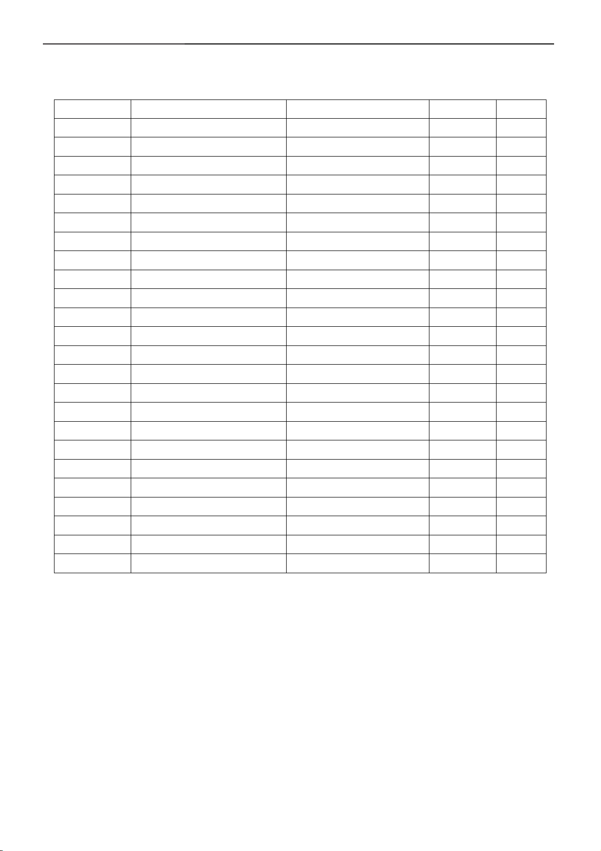
Revision List
Revision Release Date Revise history TPV model
TC8SGHHKWDDNHC
A00 Mar.-11-2008 Initial Release
A01 May.-09-2008 Add new BOM
A02 May.-13-2008 Add new BOM
TC8SGHHKWDDDHC
TC8GGHHKWDDDHC
TC8MGHHKWDDDHC
TC8SGHHMWDDZHC
TC8SGHHLWDDZHC
TC8GGHHLWDDDHC
TC8MGHHKWDDNHC
TC8MGHHKWDDDHN
TC8GGHHKWDDNHC
TC8MGHHMWDDDHC
TC8MGHHLWDDDHC
TC8MGHHJWDDDHC
TC8MGHHMWDDFHC
TC8MGHHFWDDDHC
TC8MGHHBWDDD4C
TC8SGHHFWDDZHC
TC8SGHHJWDDZHC
A03 Jul.-05-2008 Add new BOM
Change Y value to Ymin
A04 Dec.-24-2008
(min luminance value)in
item 10
TC8GGHHFWDDDHC
TC8GGHHJWDDDHC
TC8GGHHMWDDFHC
TC8SGHHMWDDEHC
ALL
2
22" LCD Color Monitor Dell E228WFPc
ECN History
ECN No. Change Description Service Deposition Cut-in date MSR
3

22" LCD Color Monitor Dell E228WFPc
Important Safety Notice
Proper service and repair is important to the safe, reliable operation of all AOC Company Equipment. The service
procedures recommended by AOC and described in this service manual are effective methods of performing
service operations. Some of these service operations require the use of tools specially designed for the purpose.
The special tools should be used when and as recommended.
It is important to note that this manual contains various CAUTIONS and NOTICES which should be carefully read
in order to minimize the risk of personal injury to service personnel. The possibility exists that improper service
methods may damage the equipment. It is also important to understand that these CAUTIONS and NOTICES ARE
NOT EXHAUSTIVE. AOC could not possibly know, evaluate and advise the service trade of all conceivable ways in
which service might be done or of the possible hazardous consequences of each way. Consequently, AOC has not
undertaken any such broad evaluation. Accordingly, a servicer who uses a service procedure or tool which is not
recommended by AOC must first satisfy himself thoroughly that neither his safety nor the safe operation of the
equipment will be jeopardized by the service method selected.
Hereafter throughout this manual, AOC Company will be referred to as AOC.
WARNING
Use of substitute replacement parts, which do not have the same, specified safety characteristics may create
shock, fire, or other hazards.
Under no circumstances should the original design be modified or altered without written permission from AOC.
AOC assumes no liability, express or implied, arising out of any unauthorized modification of design.
Servicer assumes all liability.
FOR PRODUCTS CONTAINING LASER:
DANGER-Invisible laser radiation when open. AVOID DIRECT EXPOSURE TO BEAM.
CAUTION-Use of controls or adjustments or performance of procedures other than those specified herein may
result in hazardous radiation exposure.
CAUTION -The use of optical instruments with this product will increase eye hazard.
TO ENSURE THE CONTINUED RELIABILITY OF THIS PRODUCT, USE ONLY ORIGINAL MANUFACTURER'S
REPLACEMENT PARTS, WHICH ARE LISTED WITH THEIR PART NUMBERS IN THE PARTS LIST SECTION
OF THIS SERVICE MANUAL.
Take care during handling the LCD module with backlight unit
-Must mount the module using mounting holes arranged in four corners.
-Do not press on the panel, edge of the frame strongly or electric shock as this will result in damage to the screen.
-Do not scratch or press on the panel with any sharp objects, such as pencil or pen as this may result in damage to
the panel.
-Protect the module from the ESD as it may damage the electronic circuit (C-MOS).
-Make certain that treatment person’s body is grounded through wristband.
-Do not leave the module in high temperature and in areas of high humidity for a long time.
-Avoid contact with water as it may a short circuit within the module.
-If the surface of panel becomes dirty, please wipe it off with a soft material. (Cleaning with a dirty or rough cloth
may damage the panel.)
4
22" LCD Color Monitor Dell E228WFPc
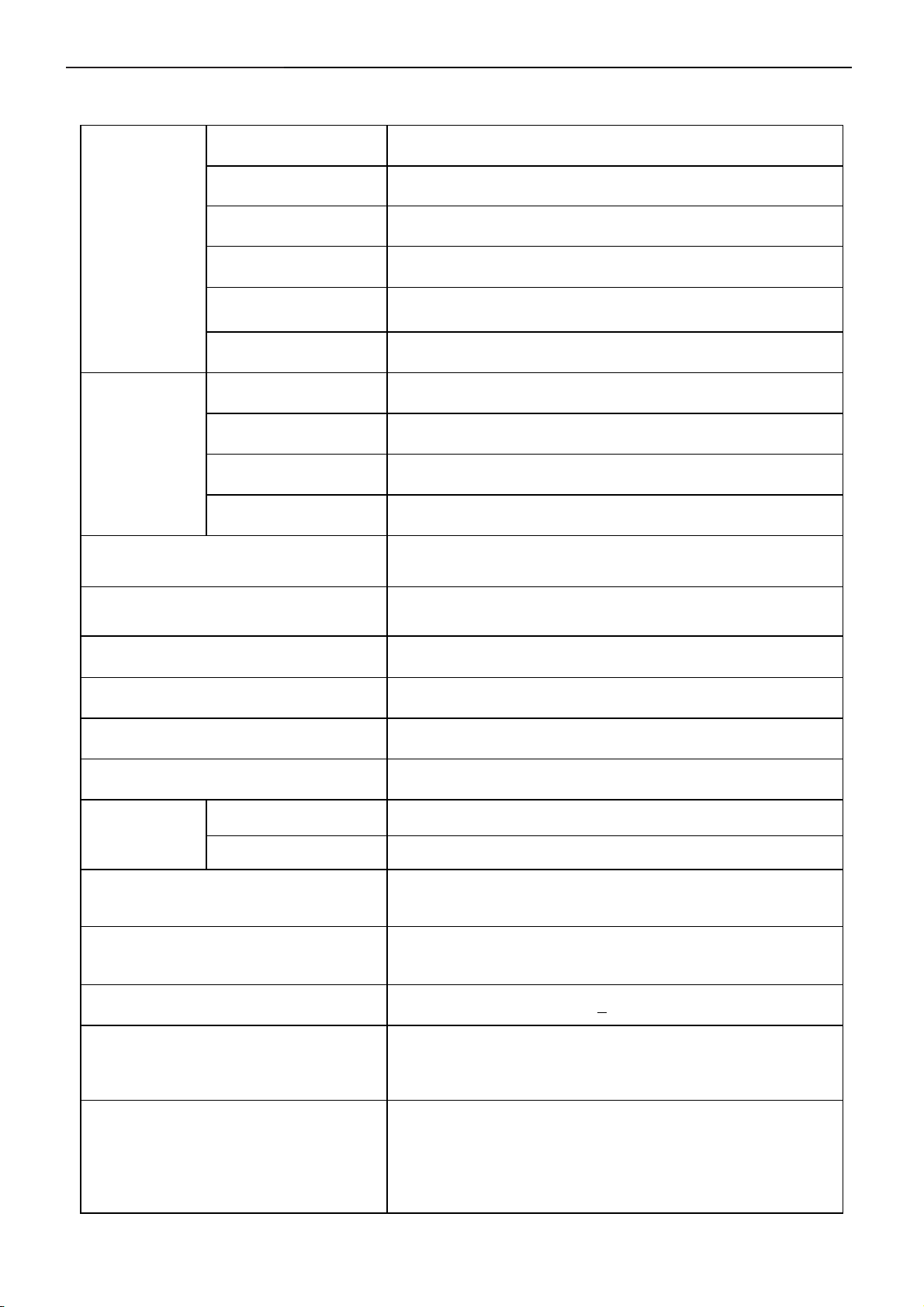
1. Monitor Specifications
Screen type Active matrix - TFT LCD
Panel Type
Size
LCD Panel
Pixel pitch
Viewable angle
Response time 5ms(type)
Video R, G, B Analog Interface, DVI digital Interface
Separate Sync H/V TTL
Input
H-Frequency 30kHz – 83kHz
V-Frequency 56 - 75Hz
Display Colors 16.7M
Luminance of White(Center of screen)
Contrast Ratio(Center of screen)
LTM220M1-L01
22 inches (22-inch viewable image size)
0.282mm(H) x 0.282mm(V)
160° (vertical) typ, 160° (horizontal) typ
cd/m2
300
1000
Dot Clock 165MHz (Max.)
Max. Resolution
Plug & Play VESA DDC
EPA ENERGY
®
STAR
Input Connector
Maximum Screen Size
Power Source
Environmental
Considerations
Weight
ON Mode <45W
OFF Mode <1W
1680 x 1050 at 60 Hz
15-pin D-subminiature, blue connector;
DVI-D, white connector
473.76mm(H) x 296.1mm(V)
100 to 240 VAC / 50 or 60 Hz +
Operating Temp: 5° to 35°C
Operating Humidity: 10% to 80%
Storage Temp.: -20° to 60°C
Weight with packaging: 20.94 lbs (9.5 kg)
Weight with stand assembly and cables: 15.65 lbs (7.1 kg)
Weight without stand assembly: 11.46 lbs (5.2 kg)
3 Hz / 1.5A
Weight of stand assembly: 2.65 lbs (1.2 kg)
5
22" LCD Color Monitor Dell E228WFPc
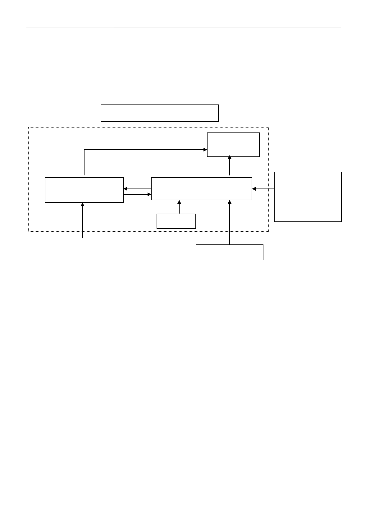
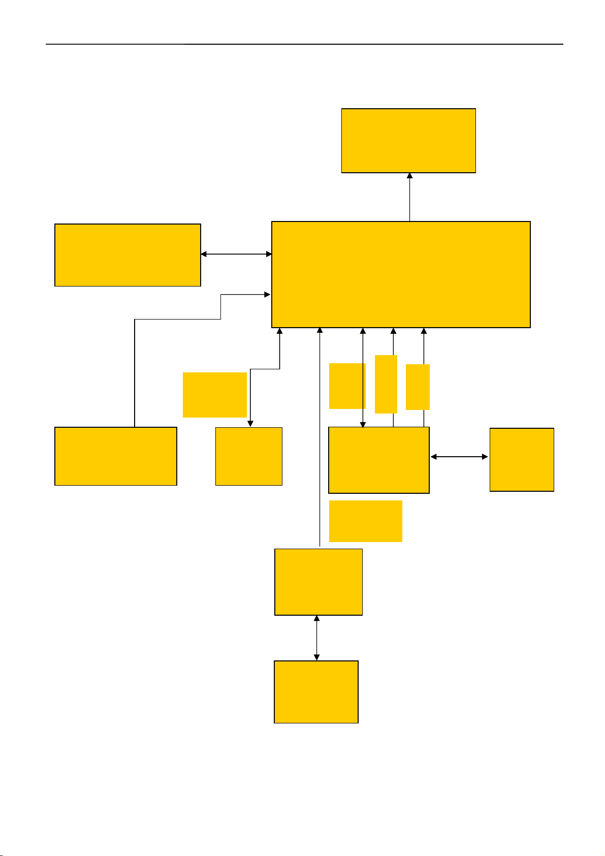
2. LCD Monitor Description
The LCD monitor will contain a main board, a power board and a key board, which house the flat panel control
logic, brightness control logic and DDC.
The power board will provide AC to DC Inverter voltage to drive the backlight of panel and the main board chips
each voltage.
Monitor Block Diagram
CCFL Drive.
Flat Panel and
CCFL backlight
Power board
Main Board
AC-IN
100-240V
Key board
Video signal, DDC
Host Computer
RS232 Connector
For white balance
adjustment in factory
mode
6

22"LCD Color Monitor Dell E228WFPc
3. Operation instructions
3.1 General Instructions
NOTE: If you change the settings and then either proceed to another menu or exit the OSD menu, the
monitor automatically saves those changes. The changes are also saved if you change the settings and then
wait for the OSD menu to disappear.
1. Push the MENU button to open the OSD menu and display the main menu.
Main Menu for Analog (VGA) Input Main Menu for digital (DVI) Input
NOTE: Auto Adjust, Positioning and Image Settings are only available when you are using the analog (VGA)
connector.
2. Push the - and + buttons to move between the setting options. As you move from one icon to another, the option
name is highlighted. See the table below for a complete list of all the options available for the monitor.
3. Push the MENU button once to activate the highlighted option.
4. Push - and + button to select the desired parameter.
5. Push MENU to enter the slide bar and then use the - and + buttons, according to the indicators on the menu, to
make your changes.
6. Push the MENU button once to return to the main menu to select another option or push the MENU button two
or three times to exit from the OSD menu.
When the OSD is locked, pressing the menu button takes the user directly to the OSD settings menu, with OSD
Lock selected. Select No (-) to unlock and allow user access to all applicable settings.
7
22"LCD Color Monitor Dell E228WFPc
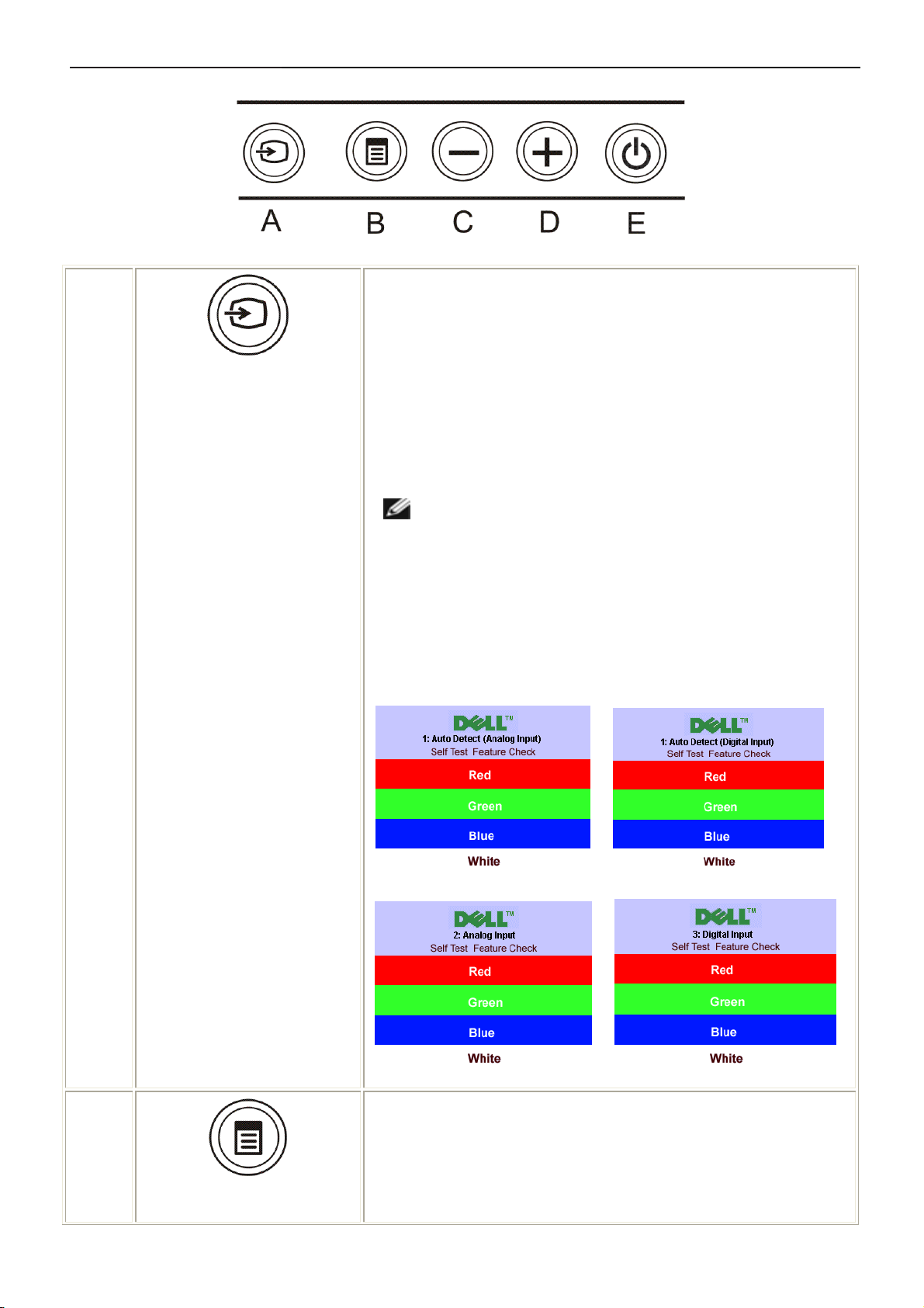
3.2 Control Buttons
Use the Input Select button to select between two different video
signals that may be connected to your monitor. Description of auto-
A
Input select
sync detect: If both VGA and DVI cables are connected to one PC, this
monitor will display an image automatically just as long as a video
signal is present in either VGA or DVI outputs. When connecting one
display to two PCs, if using screen savers, best to set both to the exact
times. Whichever mouse is moved first will activate that video input
first.
NOTE: The floating 'Dell Self-test Feature Check' dialog
appears on a black background if the monitor cannot sense a
video signal. Using the input select button, select the desired
input to be tested either Analog Input or Digital Input. Disconnect
the video cable from the video card and the Dell Self-test Feature
Check dialogue box will appear if the display is operating
correctly.
or
The Menu button is used to open and exit the on-screen display
(OSD), and exit from menus and sub-menus. See Using the OSD
B
OSD menu / select
Menu.
8
or
22"LCD Color Monitor Dell E228WFPc
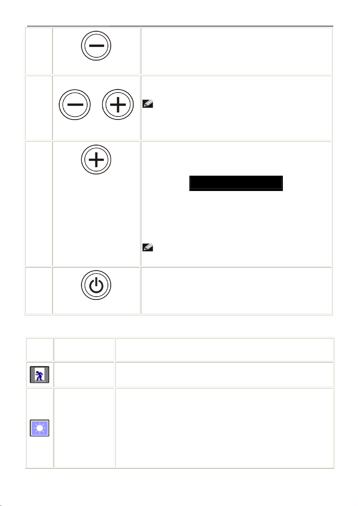
C
C, D
D
Brightness/Contrast Hot Key
Down (-) and Up (+)
Auto Adjust
Use this button for direct access to the "Brightness" and "Contrast"
control menu.
Use these buttons to adjust (decrease/increase ranges) items in the
OSD menu.
NOTE: You can activate automatic scroll feature by pressing
and holding either + or - button.
Use this button to activate automatic setup and adjust menu. The
following dialog appears on a black screen as the monitor self-adjusts
to the current input:
Auto Adjust In Progress
Auto Adjustment allows the monitor to self-adjust to the incoming video
signal. After using Auto Adjustment, you can further tune your monitor
by using the Pixel Clock (Coarse) and Phase (Fine) controls under
E
Power Button and Indicator
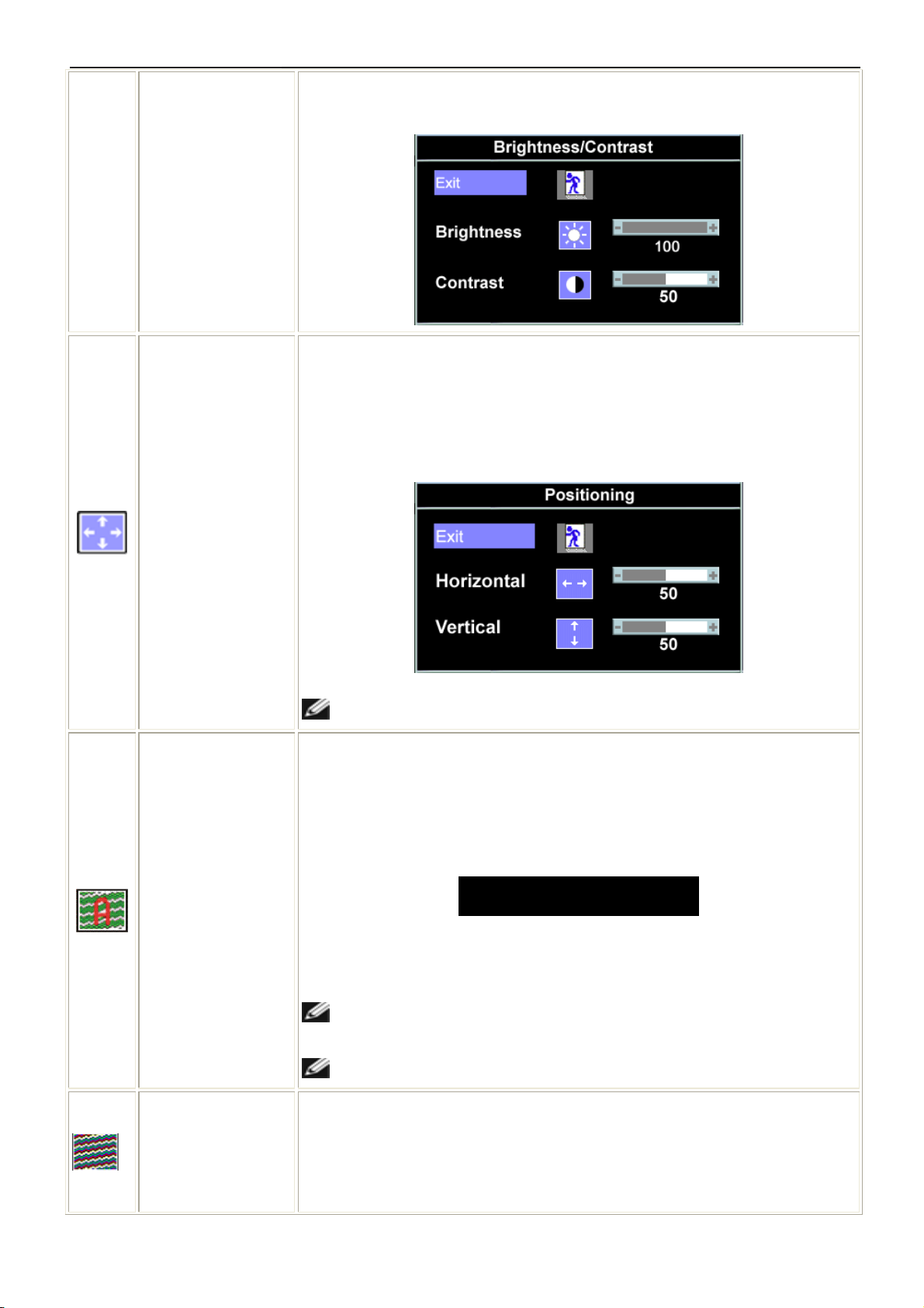
3.3 Adjusting the Picture
Icon
Menu and Submenus
Exit
Brightness/
Image Settings.
NOTE: Auto Adjust will not occur if you press the button
while there are no active video input signals, or attached cables.
Use the power button to turn the monitor on and off.
The green light indicates the monitor is on and fully functional. An
Description
Select to exit the Main menu.
Brightness adjusts the luminance of the backlight.
amber light indicates power save mode.
Contrast
Adjust Brightness first, then adjust Contrast only if further adjustment is
necessary.
Push the + button to increase luminance and push the - button to decrease
luminance (min 0 ~ max 100).
Contrast adjusts the degree of difference between darkness and lightness on the
monitor screen.
9
22"LCD Color Monitor Dell E228WFPc
Push the + button to increase the contrast and push the - button to decrease the
Positioning:
Horizontal
Vertical
contrast (min 0 ~ max 100).
Positioning moves the viewing area around on the monitor screen.
When making changes to either the Horizontal or Vertical settings, no changes
occur to the size of the viewing area. The image shifts in response to your
selection.
Minimum is 0 (-) and maximum is 100 (+)
.
Auto Adjust
Image settings:
NOTE: When using DVI source, the Positioning option is not available.
Even though your computer recognizes your monitor on startup, the Auto
Adjustment function optimizes the display settings for use with your particular
setup.
Select to activate automatic setup and adjustment. The following dialog appears
on a black screen as the monitor self-adjusts to the current input:
Auto Adjust In Progress
Auto Adjustment allows the monitor to self-adjust to the incoming video signal.
After using Auto Adjustment, you can further tune your monitor by using the Pixel
Clock (Coarse) and Phase (Fine) controls under Image Settings.
NOTE: In most cases, Auto Adjust produces the best image for your
configuration.
NOTE: When using DVI source, the Auto Adjust is not available.
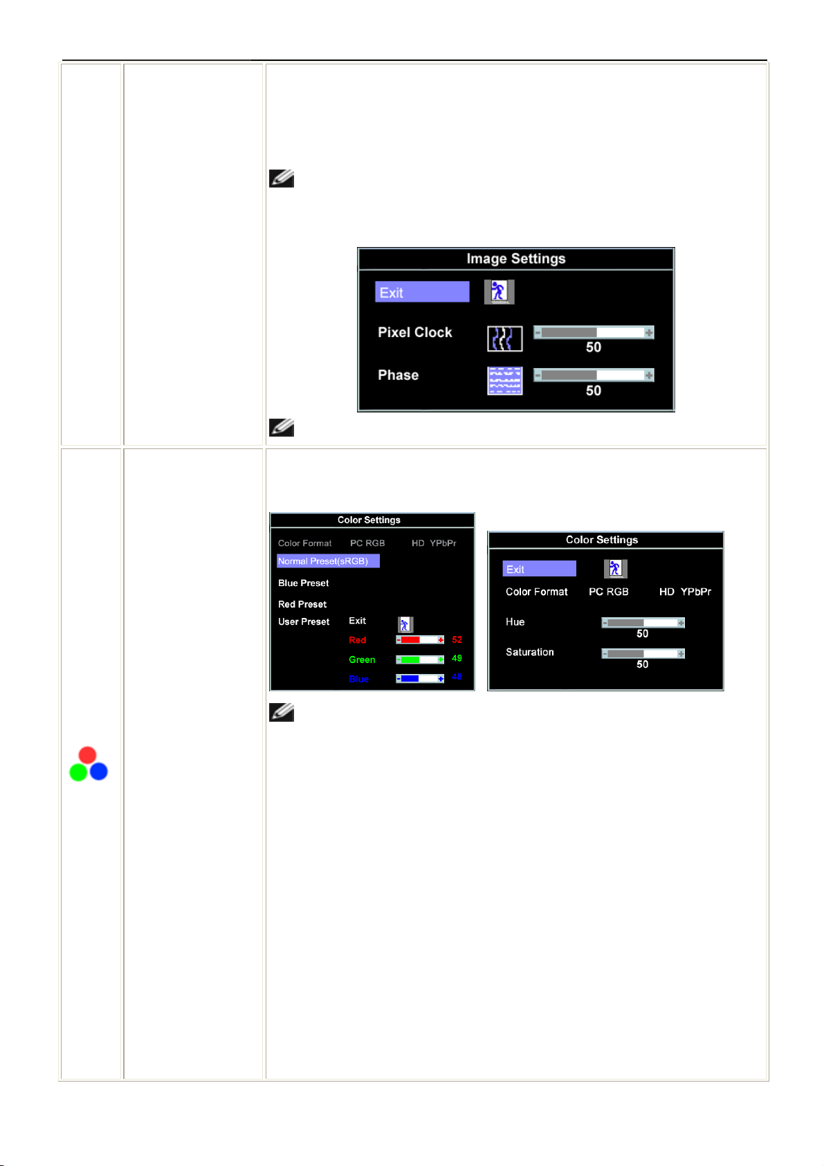
The Phase and Pixel Clock adjustments allow you to more closely adjust your
monitor to your preference. These settings are accessed through the main OSD
menu, by selecting Image Settings.
10
22"LCD Color Monitor Dell E228WFPc
Pixel Clock
(Coarse)
Phase (Fine)
Color Settings
Use the - and + buttons to make adjustments. (Minimum: 0 ~ Maximum: 100)
If satisfactory results are not obtained using the Phase adjustment, use Pixel
Clock (Coarse) and then use Phase (fine), again.
NOTE: This function may change the width of the display image. Use the
Horizontal function of the Position menu to center the display image on the
screen.
NOTE: When using DVI source, the Image Settings option is not available.
Color Settings adjusts the color temperature, color hue, and saturation.
Color Format
Blue Preset
The color hue is most noticeable in areas of white.
NOTE: Pixel Clock and Phase Adjustments are only available for
"VGA" input.
To achieve the different color domain for PC RGB and HD YPbPr ( HD YPbPr is
suitable for HD video playback over DVI. PC RGB is suitable for normal PC
graphics display over DVI.).
Blue Preset is selected to obtain a bluish tint. This color setting is typically used
for text based applications (spreadsheets, programming, text editors, etc.).
Red Preset
Normal Preset
Red Preset is selected to obtain a redder tint. This color setting is typically used
for color-intensive applications (photograph image editing, multimedia, movies,
etc.).
Normal Preset is selected to obtain the default (factory) color settings. This
setting is also the “sRGB” standard default color space.
11

22"LCD Color Monitor Dell E228WFPc
User Preset
Hue
Saturation
User Preset: Use the plus and minus buttons to increase or decrease each of the
three colors (R, G, B) independently, in single digit increments, from 0 to 100.
This feature can make color shift of video image to green or purple. This is used
to adjust for desired flesh tone color. Use - or + to adjust the hue from '0' to '100'
makes video image shade into greenish.
makes video image shade into purplish.
NOTE: Hue adjustment only available for video playback via DVI using
HD YPbPr.
makes video image looks more monochrome.
makes video image looks more colorful.
NOTE: Saturation adjustment only available for video playback via DVI
using HD YPbPr.
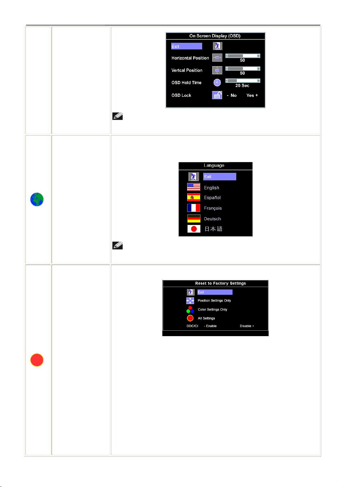
OSD Settings:
Horizontal Position
Vertical Position
OSD Hold Time
OSD Lock
Adjust the settings for the OSD, including the location and the amount of time the
menu remains on-screen.
Position of the OSD:
● To adjust the horizontal position of the OSD, use the - and + buttons, and move
OSD to the left and right.
● To adjust the vertical position of the OSD, use the - and + buttons, and move
OSD down and up.
OSD Hold Time:
The OSD stays active for as long as it is in use. Adjusting the hold time, sets the
length of time the OSD remains active after the last time you pressed a button.
Use the - and + buttons to adjust the slider in 5 second increments, from 5 to 60
seconds.
OSD Lock:
Controls user access to adjustments. When Yes (+) is selected, no user
adjustments are allowed. All buttons are locked except the menu button.
NOTE: When the OSD is locked, pressing the menu button takes the user
directly to the OSD settings menu, with OSD Lock selected. Select No (-) to
unlock and allow user access to all applicable settings.
12
22"LCD Color Monitor Dell E228WFPc
NOTE: You can also lock or unlock the OSD by pushing and holding the
Menu button for 15 seconds.
Language
Factory Reset:
Select to have the OSD display in one of five languages (English, French,
Spanish, German, or Japanese).
NOTE: The change only affects the OSD. It has no effect on any software
running on the computer.
Reset the OSD menu options to the factory preset values.
DDC/CI: — DDC/CI (Display Data Channel/Command Interface) allows your
monitor parameters (brightness, color balance etc) to be adjustable via software
on your PC. You can disable this feature by selecting "Disable".
Enable this feature for best user experience and optimum performance of your
monitor.
Exit — Select to exit out of Reset to Factory Settings menu without resetting any
OSD options.
Position settings only — Change the settings for Image Position back to
original factory settings.
Color settings only — Change the Red, Green, and Blue settings back to their
original factory settings and set the default setting for Normal Preset.
13
22"LCD Color Monitor Dell E228WFPc
All settings — Change all the user-adjustable settings including color, position,
and brightness, contrast, and OSD hold time to the factory defaults. The
language of the OSD does not change.
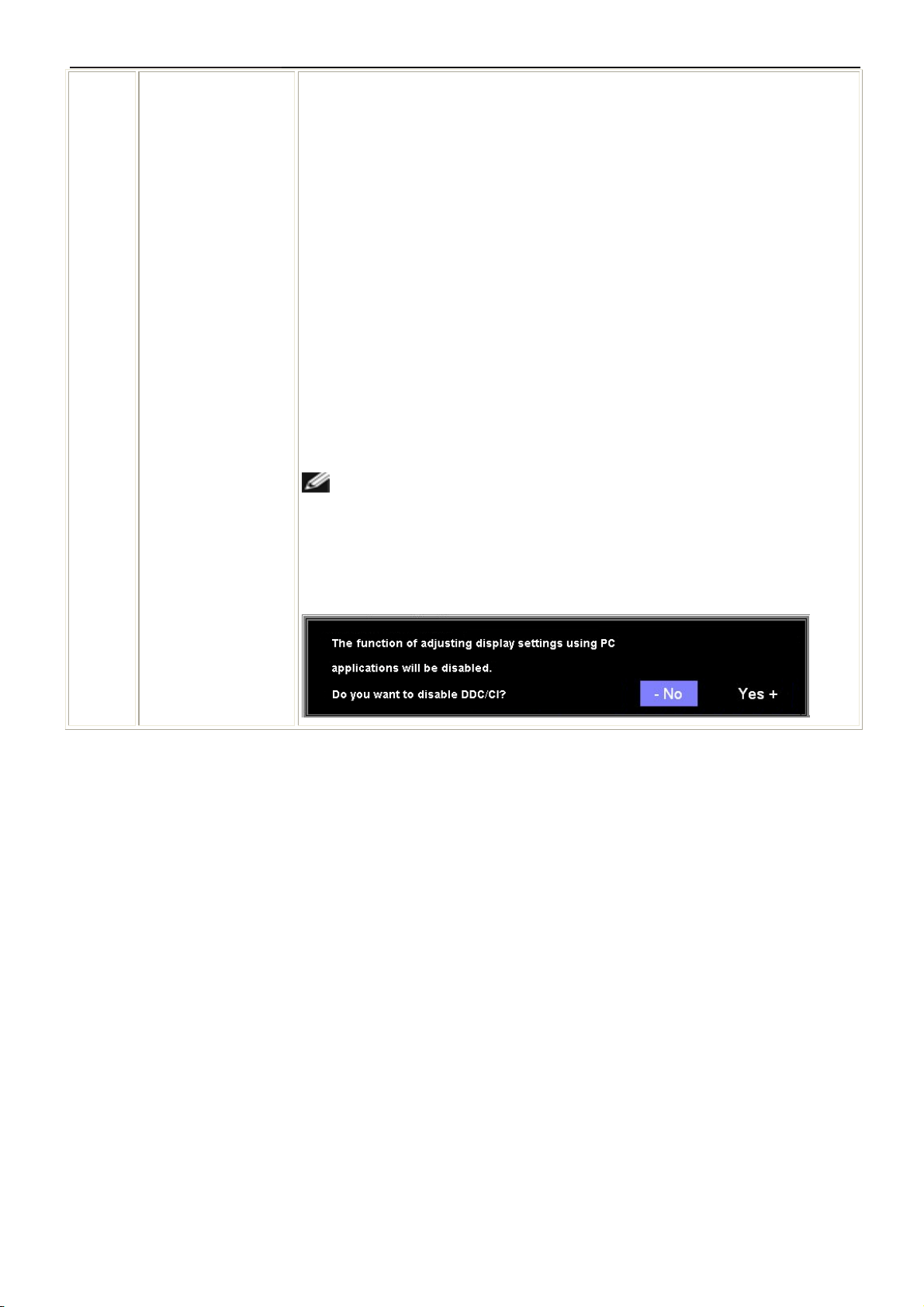
DDC/CI: — Enable the DDC/CI control function.
DDC/CI (Display Data Channel/Command Interface) allows your monitor
parameters (brightness, color balance etc) to be adjustable via software on your
PC.
Default is "Enable". You can disable this feature by selecting "Disable".
For best user experience and optimum performance of your monitor, keep this
feature enabled.
NOTE: If user select "Disable", display Warning message box as below.
Select "Yes" disable DDC/CI and return to "Factory Reset" menu. Warning
message time-out in 20 sec.
14
22"LCD Color Monitor Dell E228WFPc
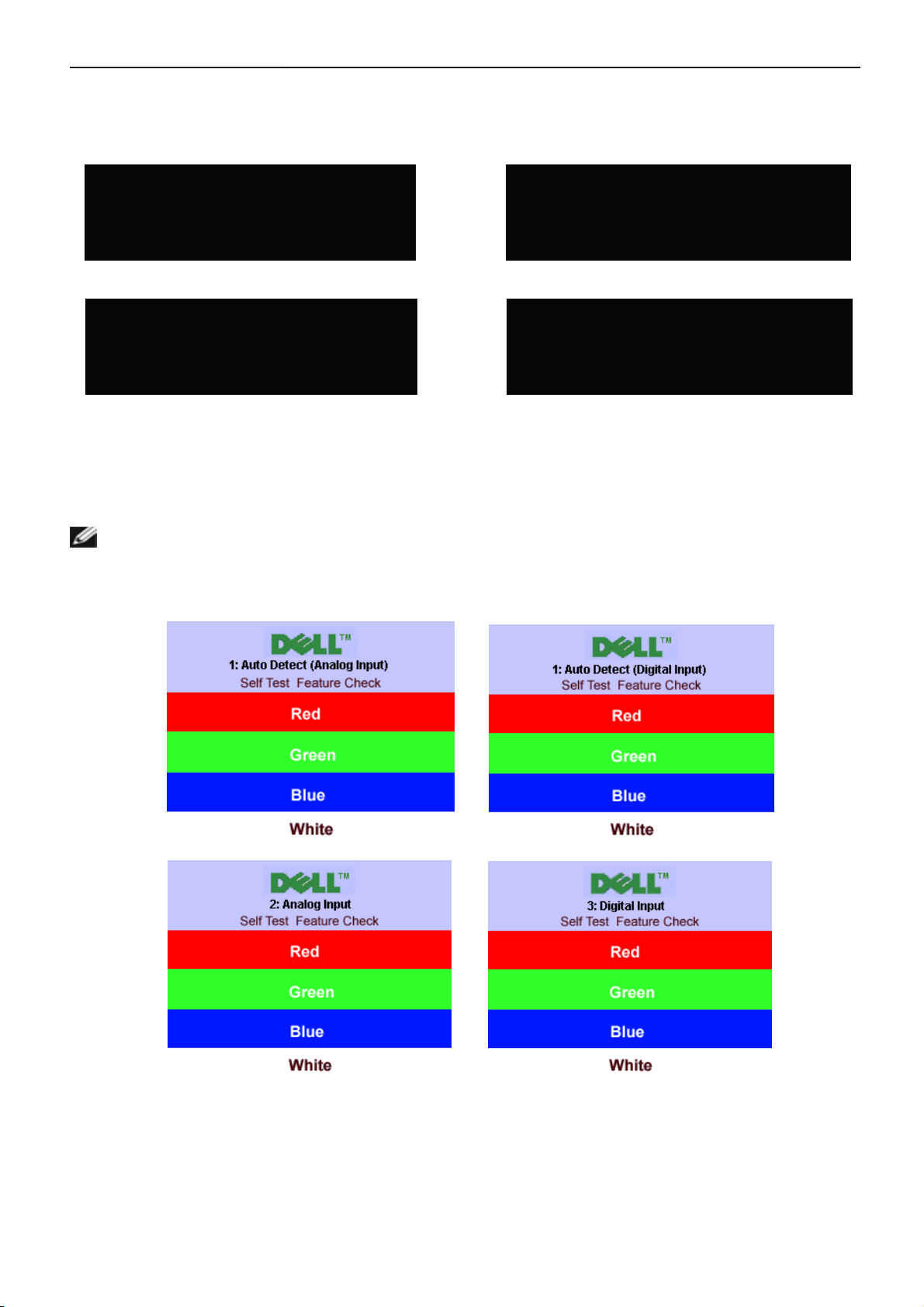
OSD Warning Messages
One of the following warning messages may appear on the screen indicating that the monitor is out of
synchronization.
1. Auto Detect (Analog Input)
Cannot Display This Video Mode
or
1. Auto Detect (Digital Input)
Cannot Display This Video Mode
Optimum Resolution 1680 x1050 60Hz
Optimum Resolution 1680 x1050 60Hz
Cannot Display This Video Mode
Optimum Resolution 1680 x1050 60Hz
2. Analog Input
or
Cannot Display This Video Mode
Optimum Resolution 1680 x1050 60Hz
3. Digital Input
This means that the monitor cannot synchronize with the signal that it is receiving from the computer. Either the
signal is too high or too low for the monitor to use. See specifications for the Horizontal and Vertical frequency
ranges addressable by this monitor. Recommended mode is 1680 X 1050 @ 60Hz.
NOTE: The floating Dell Self-test Feature Check dialog appears on-screen if the monitor cannot sense a
signal cable.
or
or
Occasionally, no warning message appears, but the screen is blank. This could also indicate that the monitor is not
synchronizing with the computer.
See solving problems for more information.
15
22"LCD Color Monitor Dell E228WFPc
4. Input/Output Specification
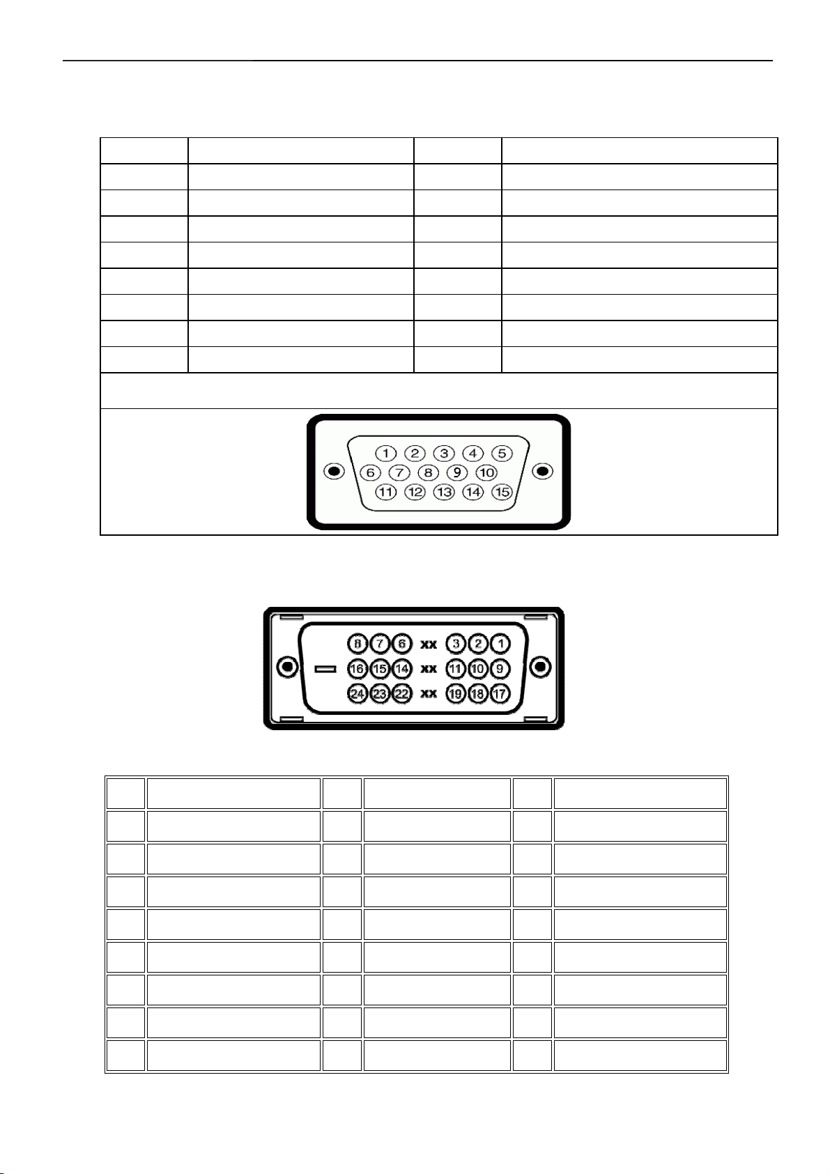
4.1 Input Signal Connector
VGA Connector:
Pin NO. Description Pin NO. Description
1. Red Video 9. DDC +5V
2. Green Video 10. GND-sync
3. Blue Video 11. GND
4. GND 12. DDC data
5. Self-test 13. H-Sync
6. R-Ground 14. V-Sync
7. G-Ground 15. DDC clock
8. B-Ground
VGA Connector layout
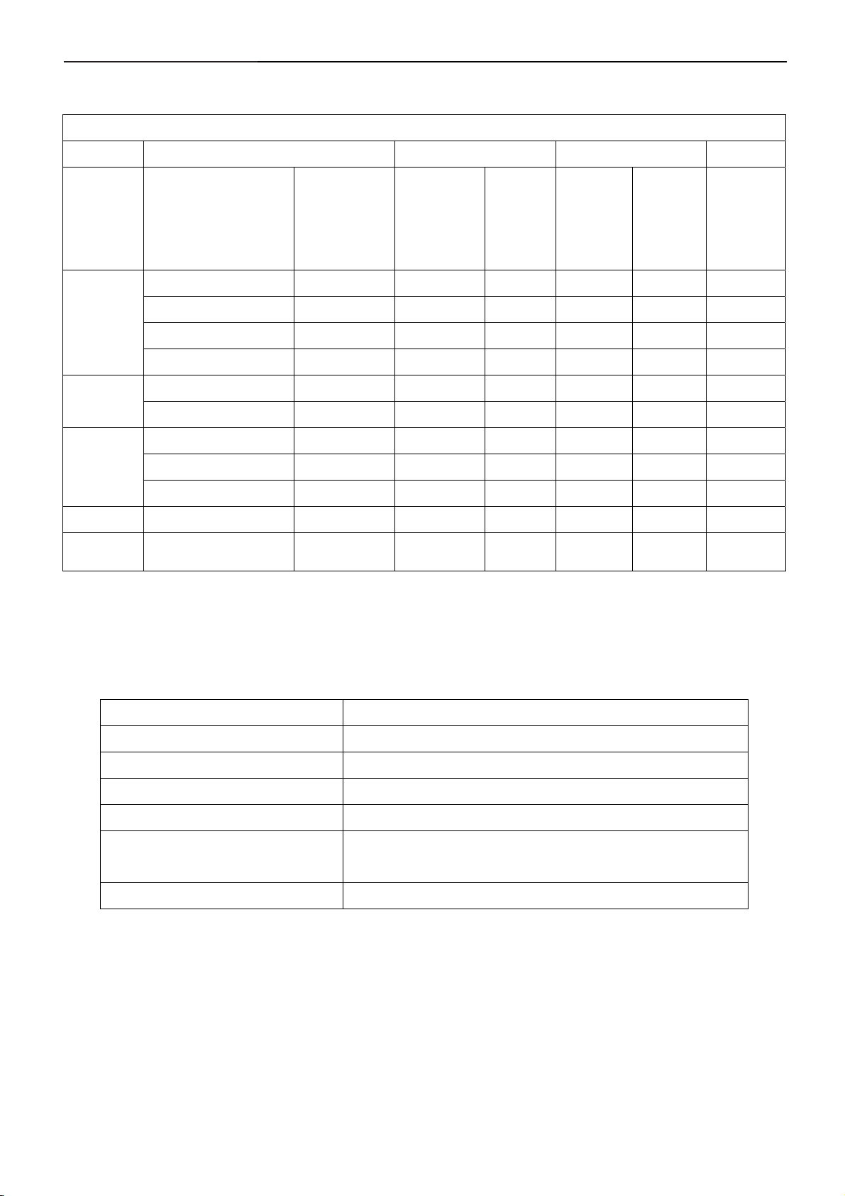
DVI Connector:
Note: Pin 1 is at the top right.
Pin Signal Assignment Pin Signal Assignment Pin Signal Assignment
T.M.D.S. Data 2-
1
T.M.D.S. Data 2+
2
T.M.D.S. Data 2 Shield
3
No Pin
4
T.M.D.S. Data 1-
9
T.M.D.S. Data 1+
10
T.M.D.S. Data 1 Shield
11
No Pin
12
T.M.D.S. Data 0-
17
T.M.D.S. Data 0+
18
T.M.D.S. Data 0 Shield
19
No Pin
20
No Pin
5
DDC Clock
6
DDC Data
7
No Connect
8
No Pin
13
+5V Power
14
Ground (for +5V)
15
Hot Plug Detect
16
16
No Pin
21
T.M.D.S. Clock Shield
22
T.M.D.S. Clock +
23
T.M.D.S. Clock -
24
22"LCD Color Monitor Dell E228WFPc
4.2 Factory Preset Display Modes
VESA MODES
Horizontal Vertical
Nominal
Mode Resolution Total
640x480@60Hz 800 x 525 31.469 N 59.940 N 25.175
VGA
XGA
SXGA
WSXGA 1680x1050@60H 2240x1899 65.16 P 60.0 P 146
DOS 720x400@70Hz 900 x 449 31.469 N 70.087 P 28.322
640x480@75Hz 840 x 500 37.500 N 75.00 N 31.500
800x600@60Hz 1056 x 628 37.879 P 60.317 P 40.000
800x600@75Hz 1056x625 46.875 P 75.000 P 49.500
1024x768@60Hz 1344x806 48.363 N 60.004 N 65.000
1024x768@75Hz 1312x800 60.023 P 75.029 P 78.750
1152x864@75Hz 1600x900 67.500 P 75.000 P 108.00
1280x1024@60Hz 1688x1066 64.000 P 60.000 P 108.00
1280x1024@75Hz 1688x1066 79.976 P 75.025 P 135.00
Frequency
+/- 0.5kHz
Sync
Polarity
Nominal
Freq.
+/- 1 Hz
Sync
Polarity
Nominal
Pixel
Clock
(MHz)
4.3 Power Supply Requirements
A/C Line voltage range : 100 V ~ 240 V
A/C Line frequency range
Current : 1.5A max at 100V; 0.8A max at 240 V
Peak surge current : < 60A peak at 240 VAC and cold starting
Leakage current : < 3.5mA
Power line surge : No advance effects (no loss of information or defect)
DC output Voltage
: 50 ± 3Hz, 60 ± 3Hz
with a maximum of 1 half-wave missing per second
: 5VDC ± 5%; 12VDC± 5%
17

22"LCD Color Monitor Dell E228WFPc
4.4 Panel Specification
LTM220M1-L01 is a color active matrix liquid crystal display (LCD) that uses amorphous silicon TFT (Thin Film
Transistor) as switching components. This model is composed of a TFT LCD panel, a driver circuit and a back light
unit. The resolution of a 22” is 1680 x1050 and this model can display up to 16.7 millions colors.
Features
High contrast ratio, high aperture structure
TN (Twisted Nematic) mode
Wide Viewing Angle
High speed response
WSXGA+ (1680 x 1050 pixels) resolution
Low power consumption
DE (Data Enable) only mode
LVDS (Low Voltage Differential Signaling) interface (2pixel/clock)
Compact Size Design
RoHS, TCO 03’ compliance
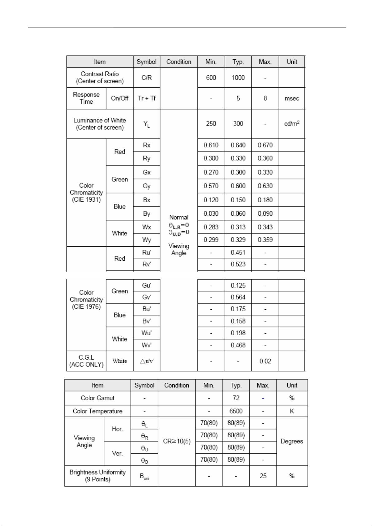
4.4.1 Display Characteristics
18
22"LCD Color Monitor Dell E228WFPc
4.4.2 Optical Characteristics
(Ta = 25 ± 2°C, VDD=5V, fv= 60Hz, fDCLK=59.6MHz, IL = 7.5mArms)
19
22"LCD Color Monitor Dell E228WFPc
4.5 Definition of Pixel Defects
4.5. 1.Description
These inspection standards shall be applied to LCD Module supplied by SAMSUNG LTM220M1-L01
Optoelectronics Corporation.
4.5.2 The environmental condition of inspection
viewing distance 35 ~ 50 cm
ambient illumination 300 ~ 700 Lux (normally 500 Lux)
ambient temperature 25 + - 5 'C
The surface of the module and the inspector's
viewing angle
display pattern Pure R, G, B, Black, White, Dot Gray pattern
inspection area Active area
4.5.3 Classification of defects
dark / bright spots:
points on the display which appear dark / bright and remain unchanged in size
dark / bright lines:
lines on the display which appear dark / bright and remain unchanged in size
polarizer scratch:
when the unit is lit a light, line is seen across a darker background; line does not vary in size
polarizer dent:
when the unit is lit a light, light(white) spots appear against a darker background, and do not vary in size
bright/dark dot:
a sub-pixel (R, G, B dot) stuck off / on
line of view shall be at 90 degrees(TN)
90±45 (PVA)
4.5.4 Inspection Criteria
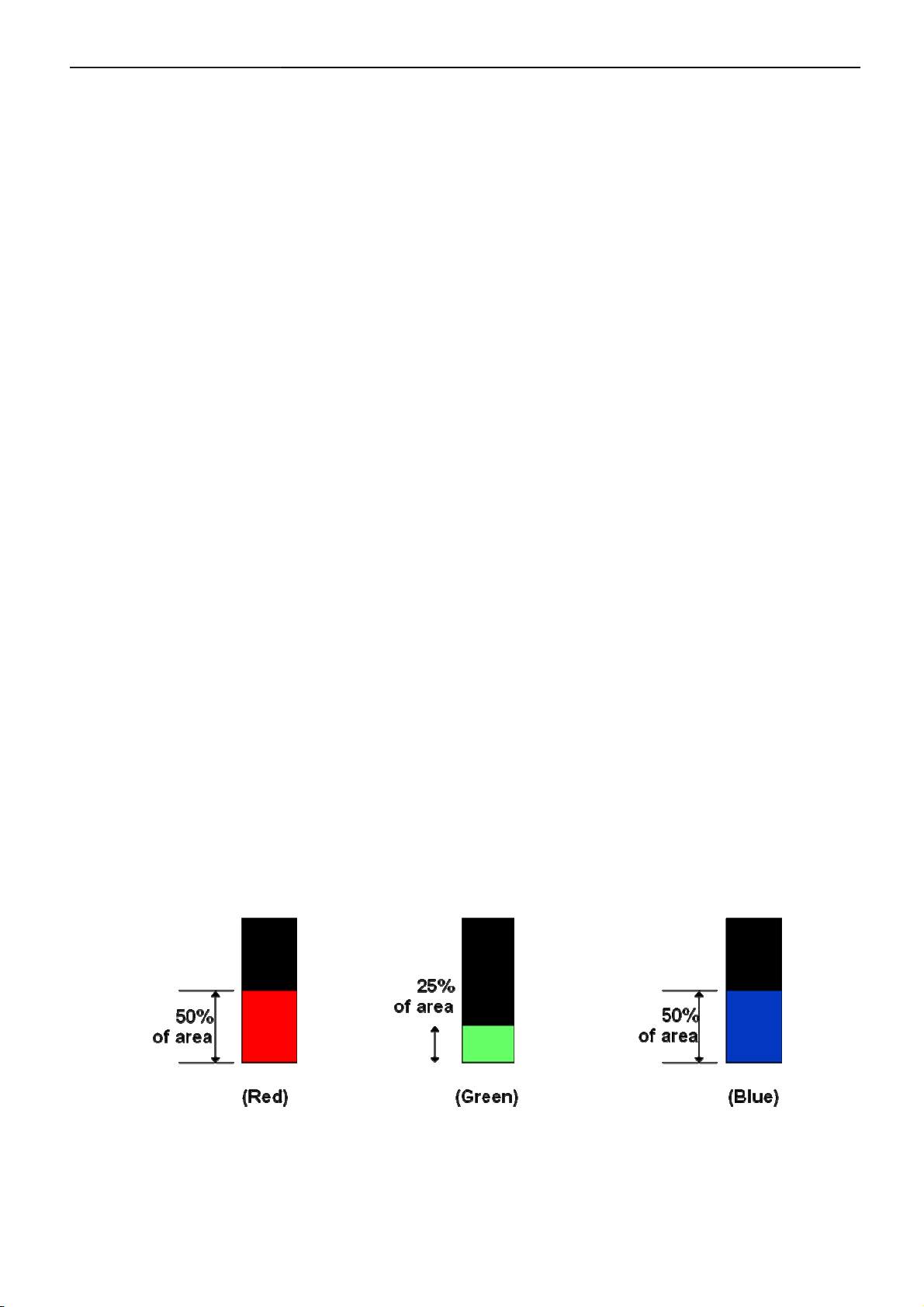
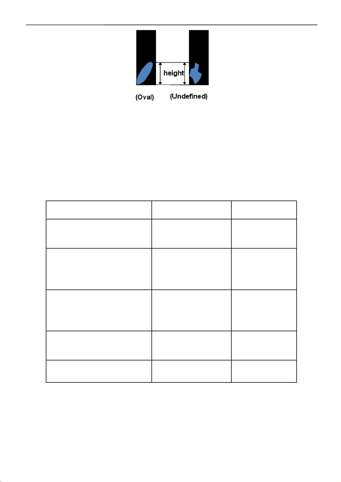
(1) . Definition of Partial dot
20
22"LCD Color Monitor Dell E228WFPc
When bright area in a sub-pixel(red or blue) exceed half size of a sub-pixel, that sub-pixel can be counted as a
bright dot.
When bright area in a sub-pixel(green) exceed a third size of a sub-pixel, that sub-pixel can be counted as a bright
dot.
Oval and undefined shape of Partial dot is defined as height of dot.
When bright area in a sub-pixel (R, B) is under 20% of a sub-pixel, that sub-pixel can be ignored.
When bright area in a sub-pixel (G) is under 10% of a sub-pixel, that sub-pixel can be ignored.
(2) Display Inspection
Defect Type Accept (mm) Reject (mm)
Dark / bright spot *1
(foreign material,Stain,Dust)
Bright line (light lint), or
dark line (dark lint / hair)
Polarizer scratch
Polarizer dent/bubble
0.3 < D ≤ 0.7
N ≤ 5
0.01 < W ≤ 0.1
0.3 < L ≤ 7.0
N ≤ 3
0.01 < W ≤ 0.1
0.3 < L ≤ 7.0
N ≤ 3
0.3 < D ≤ 0.7
N ≤ 5
D > 0.7
N > 5
W> 0.1
L >7.0
N > 3
W > 0.1
L > 7.0
N > 3
D > 0.7
N > 5
Maximum allowable number of defects N ≤ 8 N > 8
21
22"LCD Color Monitor Dell E228WFPc
5. Block Diagram
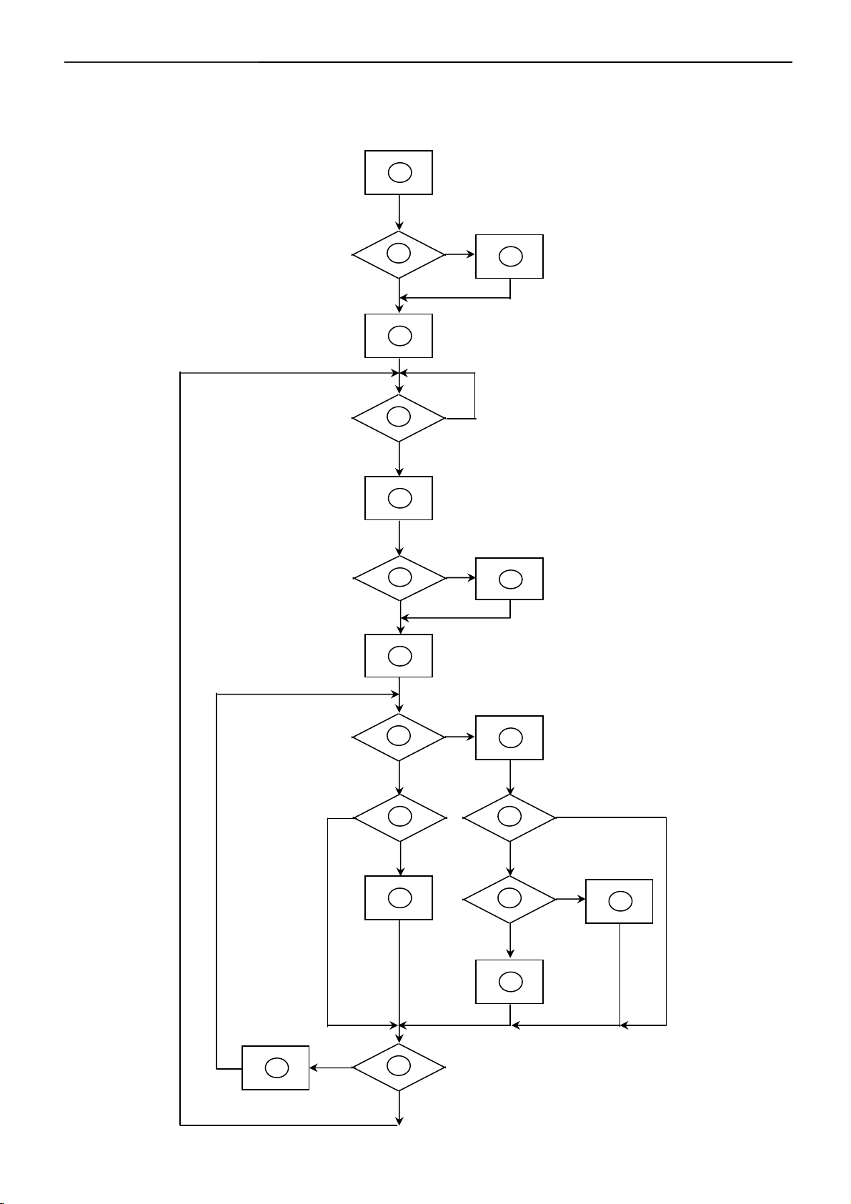
5.1 Software Flow Chart
1
2
4
Y
N
3
N
5
6
9
10
12
N
Y
7
Y
N
Y
N
11
13
8
N
Y
14
18
N
19
Y
22
15
17
Y
N
16
Y

22"LCD Color Monitor Dell E228WFPc
1) MCU Initializes.
2) Is the EEprom blank?
3) Program the EEprom by default values.
4) Get the PWM value of brightness from EEprom.
5) Is the power key pressed?
6) Clear all global flags.
7) Are the AUTO and SELECT keys pressed?
8) Enter factory mode.
9) Save the power key status into EEprom. Turn on the LED and set it to green color. Scalar initializes.
10) In standby mode?
11) Update the lifetime of back light.
12) Check the analog port, are there any signals coming?
13) Does the scalar send out an interrupt request?
14) Wake up the scalar.
15) Are there any signals coming from analog port?
16) Display "No connection Check Signal Cable" message. And go into standby mode after the message
disappears.
17) Program the scalar to be able to show the coming mode.
18) Process the OSD display.
19) Read the keyboard. Is the power key pressed?
23
22"LCD Color Monitor Dell E228WFPc
(
)
5.2 Electrical Block Diagram
5.2.1 Main Board
SST25LF020A-33-4C-SAE
Flash Memory
(U402)
GM5766H-LF PQFP-128
(Include MCU, ADC, OSD)
LCD Interface
(CN501)
(U401)
OSD Control Interface
(CN403)
EPR_SDA
EPR_SCL
EEPROM
M24C16
U403
RXD
TXD
Digital video
signal
DVI
Connector
(CN201)
DDC_SCL_DVI,
R
G
B
D-Sub
Connector
(CN202)
H
V
DB15_SDA
DB15_SCL
EEPROM
M24C02
(U202)
DDC_SDA_DVI
EEPROM
M24C02
(U201)
24
22"LCD Color Monitor Dell E228WFPc
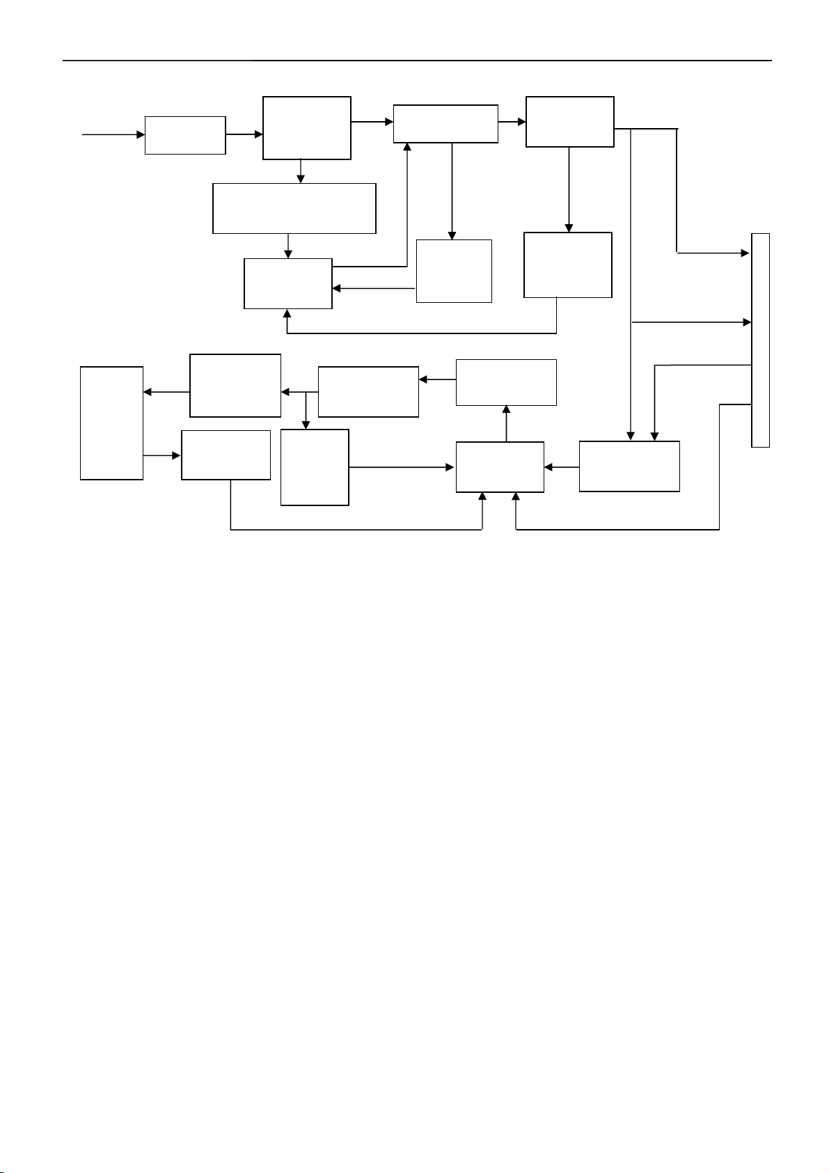
5.2.2 Inverter and Power Board
AC input
EMI
Bridge
Rectifier
and Filter
Transformer
Rectifier
diodes
Start Circuit :R905
CN902
PWM
Control
IC
Over
Voltage
Protect
Feedback
Circuit
14V
5V
Lamp
Rectify and
Output
Circuit
Transformer
MOSFET
ON/OFF
Feedback
Circuit
Over
Voltage
Protect
PWM
Control IC
ON/OFF
Control
DIM
25
 Loading...