

Page 1

Dell™ PowerVault™
MD1220 Storage Enclosures
Getting Started
With Your System
Guide de mise en route
Introdução ao uso do sistema
Introducción al sistema
Page 2

Page 3

Dell™ PowerVault™
MD1220 Storage Enclosures
Getting Started
With Your System
Regulatory Model Series E04J
Page 4

Notes, Cautions, and Warnings
NOTE: A NOTE indicates important information that helps you make better
use of your computer.
CAUTION: A CAUTION indicates potential damage to hardware or loss of
data if instructions are not followed.
WARNING: A WARNING indicates a potential for property damage,
personal injury, or death.
____________________
Information in this document is subject to change without notice.
© 2009 Dell Inc. All rights reserved.
Reproduction of these materials in any manner whatsoever without the written permission of Dell Inc.
is strictly forbidden.
Trademarks used in this text: Dell, the DELL logo, OpenManage, PowerEdge, and PowerVault are
trademarks of Dell Inc.
Other trademarks and trade names may be used in this document to refer to either the entities claiming
the marks and names or their products. Dell Inc. disclaims any proprietary interest in trademarks and
trade names other than its own.
Regulatory Model Series E04J
August 2009 P/N H476M Rev. A00
Page 5
Installation and Configuration
WARNING: Before performing the following procedure, review the safety
instructions that came with the system.
Unpacking the System
Unpack your system and identify each item.
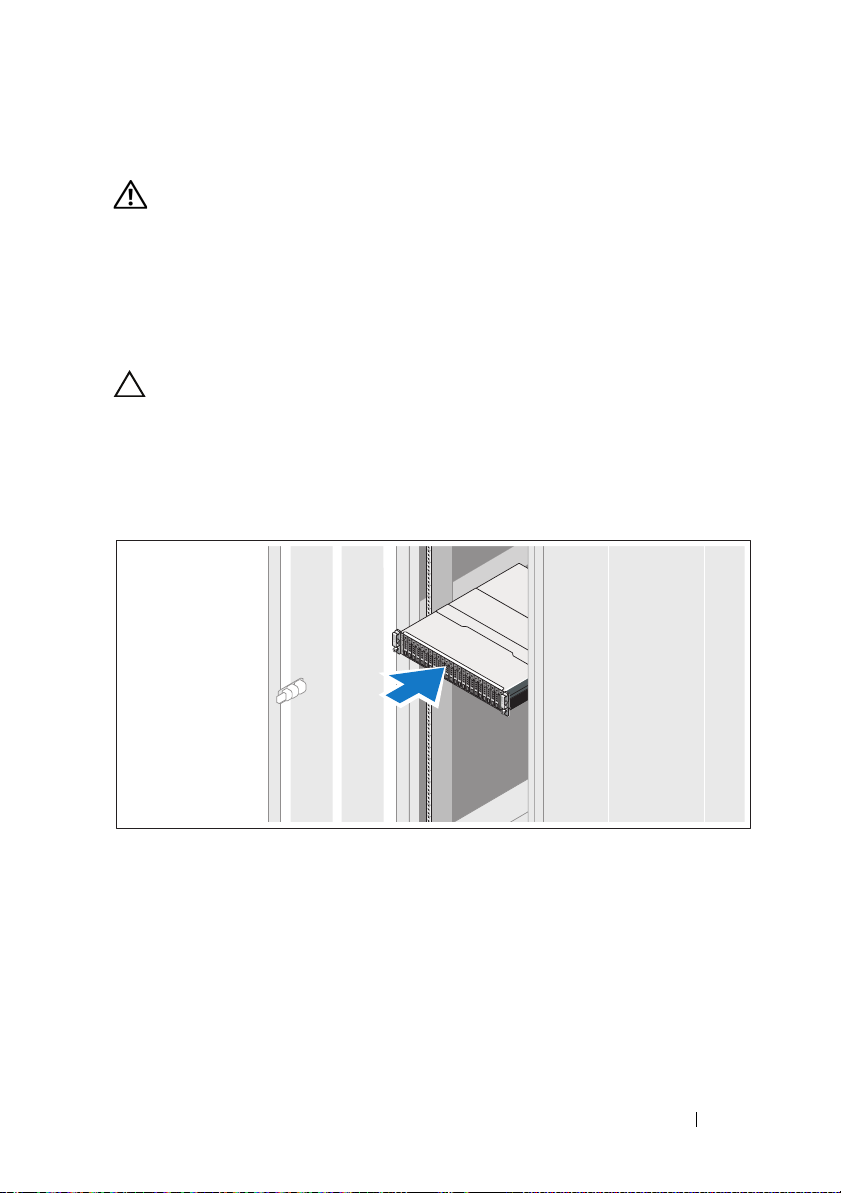
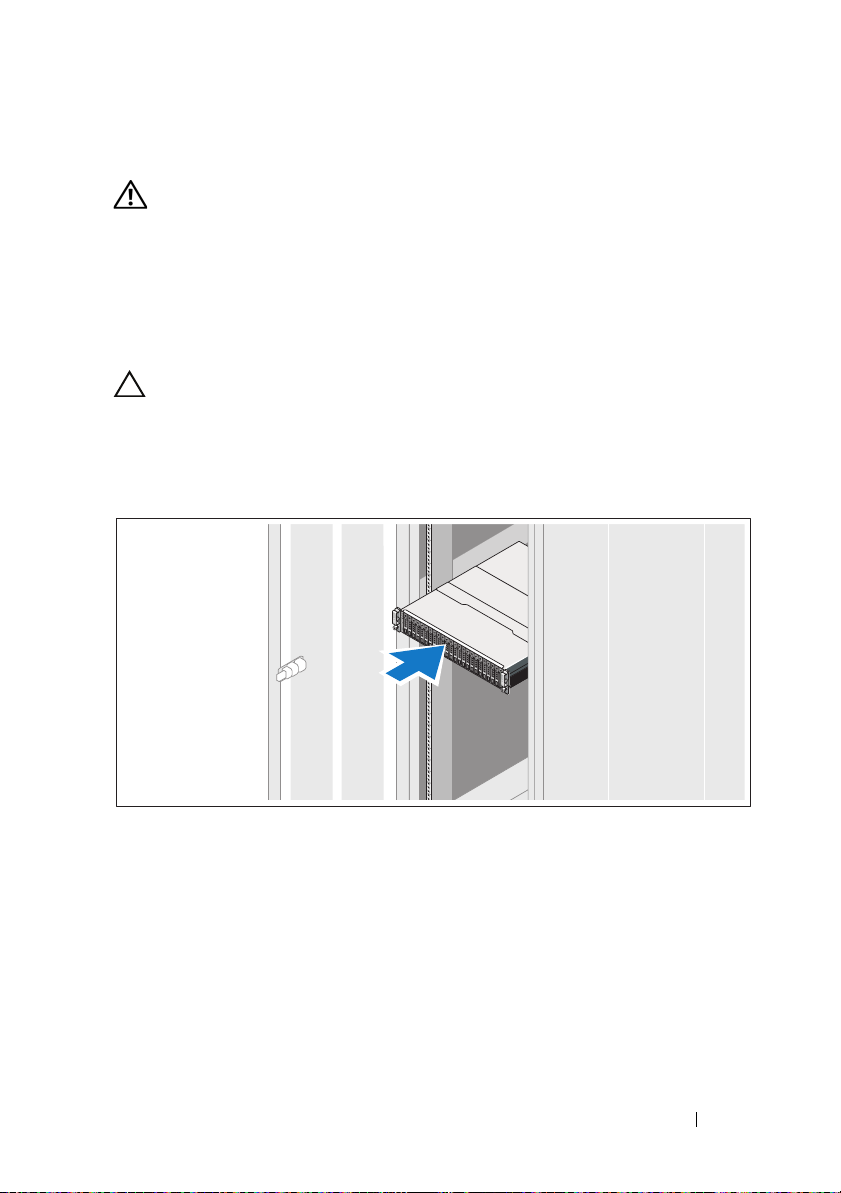
Installing the Rails and System in a Rack
CAUTION: If installed in a closed or multi-unit rack assembly, the operating
ambient temperature of the rack environment may be greater than room ambient.
Therefore, consideration should be given to installing the equipment in an
environment compatible with the maximum ambient temperature (Tma)
specified by the manufacturer. For more information, see "Technical
Specifications" on page 7.
Assemble the rails and install the system in the rack following the safety
instructions and the rack installation instructions provided with your system.
Getting Started With Your System 3
Page 6
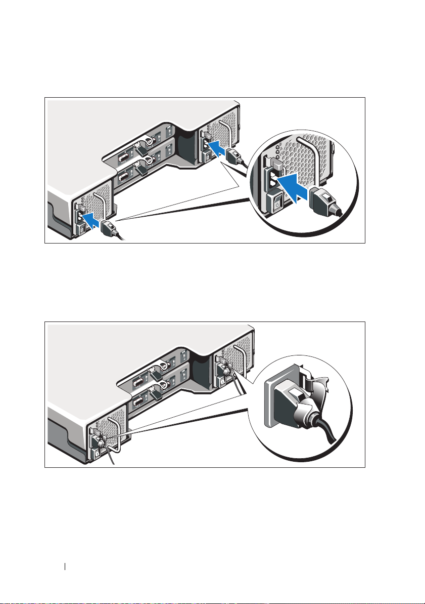
Connecting the Power Cable(s)
Ensure that the power switch is in the OFF position before connecting the
power cable(s). Connect the system’s power cable(s) to the system.
Securing the Power Cable(s)
Bend the system power cable(s) as shown in the illustration and secure the
cable(s) firmly to the bracket using the provided strap.
Plug the other end of the power cable(s) into a grounded electrical outlet or a
separate power source such as an uninterrupted power supply (UPS) or a
power distribution unit (PDU).
4 Getting Started With Your System
Page 7
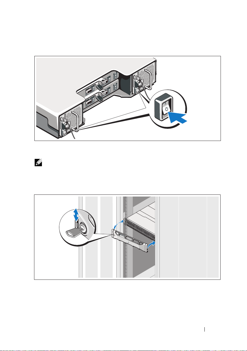
Turning On the System
Press the power switch to the ON position. The power indicators should light.
NOTE: Ensure that the storage enclosure is connected to the server and the mode
switch is set to split or unified mode before turning on the system.
Installing the Optional Bezel
Install the bezel (optional).
Getting Started With Your System 5
Page 8
Other Information You May Need
WARNING: See the safety and regulatory information that shipped with your
system. Warranty information may be included within this document or as a
separate document.
• The rack documentation included with your rack solution describes how
to install your system into a rack.
•The
• Any media that ships with your system that provides documentation
Hardware Owner’s Manual
features and describes how to troubleshoot the system and install or
replace system components. This document is available online at
support.dell.com/manuals
and tools for configuring and managing your system, including those
pertaining to the operating system, system management software,
system updates, and system components that you purchased
with your system.
NOTE: Always check for updates on support.dell.com/manuals and read the
updates first because they often supersede information in other documents.
provides information about system
.
NOM Information (Mexico Only)
The following information is provided on the device described in
this document in compliance with the requirements of the
official Mexican standards (NOM):
Importer:
Model number: E04J
Supply voltage: 100–240 V CA
Frequency: 50/60 Hz
Current consumption: 8.6 A
6 Getting Started With Your System
Page 9

Technical Specifications
Drives
SAS hard drives Up to 24 2.5-inch SAS hot-swappable hard
drives (3.0 Gbps and 6.0 Gbps)
Enclosure Management Modules (EMMs)
EMMs One or two hot-swappable modules with
temperature sensors and an audio alarm
Connectivity
Configurations Support for either of the following
configurations:
• Unified mode for direct connectivity to
24 hard drives per enclosure.
– Up to four daisy-chained storage
enclosures for a total of 96 hard drives
per controller port and 192 hard drives
per controller.
– Maximum configuration of
two dual port controllers per server for
a total of 384 drives.
– Redundant path connectivity provides
redundant data paths to each hard drive.
Redundant path configuration supports
up to four daisy-chained storage
enclosures for a total of 96 hard drives
per controller and up to 192 hard drives
per server.
• Split mode with dual EMMs provides a
direct connectivity to drives 0 through 11
and a separate direct connectivity to
drives 12 to 23. Split mode configuration
does not support daisy-chaining or
redundant data paths.
Getting Started With Your System 7
Page 10

Redundant Array of Independent Disks (RAID)
Controller Host-based RAID support using
PowerEdge™ RAID controller H800.
Management RAID management using
Dell OpenManage™ Server
Administrator 6.2 or later.
Back-Plane Board
Connectors
Sensors Two temperature sensors
Back-Panel Connectors (per EMM)
SAS connectors
• 24 SAS hard-drive connectors
• Two power supply/cooling fan
module connectors
• Two sets of EMM connectors
• One control panel connector for front LEDs
and enclosure mode switch
• One SAS IN connector for connection
to the host
• One SAS OUT connector for expansion to
an additional enclosure
NOTE: SAS connectors are SFF-8086/SFF-8088
compliant.
Serial connector One 6-pin UART mini-DIN connector
NOTE: For engineering use only.
LED Indicators
Front panel
Hard-drive carrier
• One two-color LED indicator for
• Two single-color LED indicators for
• One single-color activity LED
• One two-color LED status indicator
8 Getting Started With Your System
system status
power and split mode
per drive
Page 11

LED Indicators (continued)
EMM Three two-color LED status indicators,
one each for the two EMM SAS ports and
one for the EMM status
Power supply/cooling fan Three LED status indicators for power supply
status, power supply/cooling fan fault status,
and AC status
Switch
System identification button Located on the front control panel.
This button is used to locate a system
within a rack.
Mode switch Located on the front control panel.
This switch is used to switch the system
between unified and split mode operation.
Power Supplies
AC power supply (per power supply)
Wattage
Vo lt ag e
Heat dissipation
Maximum inrush current
600 W
100–240 VAC (8.6 A–4.3 A)
188 W
Under typical line conditions and over the
entire system ambient operating range,
the inrush current may reach 55 A per
power supply for 10 ms or less.
Available Hard Drive Power (Per Slot)
Supported hard drive power
consumption (continuous)
EMM Power (Per Slot)
Maximum power consumed by EMM 14 W at +12 V
Maximum available power 100 W at +12 V
Maximum available power 1 W at +5 V (standby)
Up to 1.2 A at +5 V
Up to 0.5 A at +12 V
Getting Started With Your System 9
Page 12

Physical
Height 8.68 cm (3.41 inches)
Width 44.63 cm (17.57 inches)
Depth 54.90 cm (21.61 inches)
Weight (maximum configuration) 23.31 kg (51.4 lb)
Weight (empty) 8.61 kg (19 lb)
Environmental
NOTE: For additional information about environmental measurements for specific
system configurations, see www.dell.com/environmental_datasheets.
Temperature
Operating
10° to 35°C (50° to 95°F) with a maximum
temperature gradation of 10°C per hour
NOTE: For altitudes above 2950 feet,
the maximum operating temperature
is derated 1ºF/550 ft.
Storage
Relative humidity
Operating
Storage
Maximum vibration
Operating
Storage
–40° to 65°C (–40° to 149°F) with
a maximum temperature gradation
of 20°C per hour
20% to 80% (noncondensing) with
a maximum humidity gradation
of 10% per hour
5% to 95% (noncondensing)
0.25 G at 3–200 Hz for 15 min
0.5 G at 3–200 Hz for 15 min
10 Getting Started With Your System
Page 13

Environmental (continued)
Maximum shock
Operating
Storage
Altitude
Operating
Storage
Airborne Contaminant Level
Class
One shock pulse in the positive z axis
(one pulse on each side of the system) of
31 G for 2.6 ms in the operational orientation
Six consecutively executed shock pulses
in the positive and negative x, y, and z axes
(one pulse on each side of the system) of
71 G for up to 2 ms
–16 to 3048 m (–50 to 10,000 ft)
NOTE: For altitudes above 2950 feet,
the maximum operating temperature is
derated 1ºF/550 ft.
–16 to 10,600 m (–50 to 35,000 ft)
G2 or lower as defined by ISA-S71.04-1985
Getting Started With Your System 11
Page 14

12 Getting Started With Your System
Page 15

Boîtiers de stockage Dell™
PowerVault™ MD1220
Guide de mise en route
Modèle réglementaire Série E04J
Page 16
Remarques, précautions et avertissements
REMARQUE : une REMARQUE indique des informations importantes qui peuvent
vous aider à mieux utiliser votre ordinateur.
PRÉCAUTION : une PRÉCAUTION indique un risque d'endommagement du
matériel ou de perte de données en cas de non respect des instructions.
AVERTISSEMENT: un AVERTISSEMENT vous avertit d’un risque
d'endommagement du matériel, de blessure corporelle ou de mort.
____________________
Les informations que contient ce document sont sujettes à modification sans préavis.
© 2009 Dell Inc. Tous droits réservés.
La reproduction de ce document, de quelque manière que ce soit, sans l'autorisation écrite de Dell Inc.
est strictement interdite.
Marques utilisées dans ce document : Dell, le logo DELL, OpenManage, PowerEdge et PowerVault
sont des marques de Dell Inc.
D'autres marques et noms de marque peuvent être utilisés dans ce document pour faire référence aux
entités se réclamant de ces marques et de ces noms ou de leurs produits. Dell Inc. dénie tout intérêt
propriétaire vis-à-vis des marques commerciales et des noms de marque autres que les siens.
Modèle réglementaire Série E04J
Août 2009 N/P H476M Rév. A00
Page 17
Installation et configuration
AVERTISSEMENT: avant de commencer, lisez les consignes de sécurité
fournies avec le système.
Déballage du système
Sortez le système de son emballage et identifiez chaque élément.
Installation des rails et du système dans un rack
PRÉCAUTION :
température ambiante du rack lors du fonctionnement du système peut être plus
élevée que celle de la pièce. Il importe donc de veiller à installer l'équipement dans
un environnement respectant la température maximale (Tma) prescrite par le
fabricant. Pour plus d'informations, voir « Caractéristiques techniques » à la page 19.
si le système est installé dans un rack clos ou multi-unités, la
Assemblez les rails et installez le système dans le rack en suivant les consignes
de sécurité et les instructions d'installation du rack fournies avec votre
système.
Guide de mise en route 15
Page 18

Branchement du ou des câbles d'alimentation
Avant de connecter les câbles d'alimentation, assurez-vous que le
commutateur d'alimentation est en position OFF (ÉTEINT). Branchez le ou
les câbles d'alimentation sur le système.
Fixation du ou des câbles d'alimentation
Repliez le(s) câble(s) comme illustré et faites-le(s) passer dans le clip, puis
fixez-le(s) à l'aide de la sangle fournie.
Branchez ensuite l'autre extrémité du ou des câbles sur une prise de courant
mise à la terre ou sur une source d'alimentation autonome (onduleur ou unité
de distribution de l'alimentation [PDU]).
16 Guide de mise en route
Page 19

Mise sous tension du système
Mettez le commutateur d'alimentation en position ON (ALLUMÉ). Les
voyants d'alimentation s'allument.
REMARQUE : assurez-vous que le boîtier de stockage est connecté au serveur et
que le commutateur de mode est configuré sur le mode divisé ou unifié avant de
mettre le système sous tension.
Installation du cadre en option
Installez le cadre (si nécessaire).
Guide de mise en route 17
Page 20

Autres informations utiles
AVERTISSEMENT: reportez-vous aux informations sur la sécurité et les
réglementations fournies avec votre système. Les informations sur la garantie se
trouvent dans ce document ou dans un document distinct.
• La documentation fournie avec le rack indique comment installer le
système dans un rack.
•Le
Manuel du propriétaire
présente les caractéristiques du système et
contient des informations de dépannage et des instructions d'installation
ou de remplacement des composants. Il est disponible en ligne sur le site
support.dell.com/manuals
.
• Tous les supports fournis avec le système contiennent de la documentation
et des outils permettant de configurer et de gérer le système, notamment
les supports du système d'exploitation, du logiciel de gestion du système,
des mises à jour système et des composants système que vous avez achetés
avec le système.
REMARQUE : vérifiez toujours si des mises à jour sont disponibles sur le site
support.dell.com/manuals et lisez-les en premier, car elles remplacent
souvent les informations que contiennent les autres documents.
Informations NOM (Mexique uniquement)
Les informations suivantes sur l'appareil décrit dans ce document sont fournies
conformément aux exigences de la Norme Officielle Mexicaine (NOM) :
Importateur : Dell Inc. de México, S.A. de C.V.
Paseo de la Reforma 2620 -11º Piso
Col. Lomas Altas
11950 México, D.F.
Numéro de modèle : E04J
Tension d'alimentation : 100–240 V CA
Fréquence : 50/60 Hz
Consommation électrique : 8,6 A
18 Guide de mise en route
Page 21

Caractéristiques techniques
Lecteurs
Disques durs SAS Jusqu'à 24 disques durs SAS remplaçables à
chaud 2,5 pouces (3,0 Gb/s et 6,0 Gb/s)
Deux EMM (modules de gestion des boîtiers)
EMM Un ou deux modules remplaçables à chaud
avec capteurs de température et alarme audio
Connectivité
Configurations L'une des configurations suivantes est prise
en charge :
• Mode unifié pour connectivité directe à
12 disques durs par boîtier.
– Jusqu'à quatre boîtiers de stockage en
marguerite pour un total de 96 disques
durs par port contrôleur et 192 disques
durs par contrôleur.
– Configuration maximale de deux
contrôleurs double ports par serveur pour
un total de 384 lecteurs.
– La connectivité à chemin redondant
fournit des chemins de données
redondants à chaque disque dur. La
configuration à chemin redondant prend
en charge jusqu'à quatre boîtiers de
stockage en marguerite pour un total de
96 disques durs par contrôleur et jusqu'à
192 disques durs par serveur.
• Mode divisé avec deux modules EMM,
permettant une connectivité directe pour
les disques 0 à 11 et une connectivité
directe distincte pour les disques 12 à 23. La
configuration en mode divisé ne prend pas
en charge la mise en marguerite ou les
chemins de données redondants.
Guide de mise en route 19
Page 22

Acronyme de « Redundant Array of Independent Disks », matrice redondante de
disques indépendants
Contrôleur Prise en charge RAID à base d'hôte utilisant
un contrôleur RAID PowerEdge™ H800
Gestion Gestion RAID à l'aide de Dell OpenManage™
Server Administrator 6.2 ou ultérieur.
Carte fond de panier
Connecteurs
Capteurs Deux capteurs de température
Connecteurs du panneau arrière (pour chaque module EMM)
Connecteurs SAS
• 24 connecteurs de disques durs SAS
• Deux connecteurs pour les modules de
ventilation/alimentation
• Deux ensembles de connecteurs EMM
• Un connecteur de panneau de commande
pour les voyants frontaux et le commutateur
de mode du châssis
• Un connecteur SAS IN (Entrée) pour la
connexion à l'hôte
• Un connecteur SAS OUT (Sortie) pour la
connexion à un boîtier supplémentaire
REMARQUE : les connecteurs SAS sont
conformes SFF-8086/SFF-8088.
Connecteur série Un connecteur mini-DIN UART à 6 broches
REMARQUE : à des fins d'ingénierie
uniquement.
Voyants
Panneau avant
20 Guide de mise en route
• Un voyant bicolore indiquant l'état du
système
• Deux voyants monochromes (alimentation
et mode divisé)
Page 23

Voyants (suite)
Support du disque dur
EMM Trois voyants d'état bicolores (un pour
Bloc d'alimentation/ventilateur de
refroidissement
Commutateur
Bouton d'identification du système Situé sur le panneau de commande avant. Ce
Commutateur de mode Situé sur le panneau de commande avant.
Blocs d'alimentation
Bloc d'alimentation CA (selon la tension en vigueur)
Puissance
Te ns i on
Dissipation thermique
Appel de courant maximal
• Un voyant d'activité monochrome
• Un voyant d'état bicolore par lecteur
chaque port SAS du module EMM et un
troisième indiquant l'état du module)
Trois voyants d'état (état du bloc
d'alimentation, panne du bloc
d'alimentation/ventilateur et état de
l'alimentation)
bouton sert à localiser un système au sein
d'un rack
Sert à basculer le système entre le mode
unifié et le mode divisé
600 W
100–240 VAC (8,6 A–4,3 A)
188 W
Dans des conditions de ligne typiques et dans
toute la gamme ambiante de fonctionnement
du système, l'appel de courant peut atteindre
55 A par bloc d'alimentation pendant un
maximum de 10 ms
Alimentation disponible pour les disques durs (par logement)
Consommation prise en charge pour
l'alimentation des disques durs (en
continu)
Jusqu'à 1,2 A à +5 V
Jusqu'à 0,5 A à +12 V
Guide de mise en route 21
Page 24

Alimentation EMM (par logement)
Puissance maximale consommée par
EMM
Puissance maximale disponible 100 W à +12 V
Puissance maximale disponible 1 W à +5 V (veille)
Caractéristiques physiques
Hauteur 8,68 cm (3,41 pouces)
Largeur 44,63 cm (17,57 pouces)
Profondeur 54,90 cm (21,61 pouces)
Poids (configuration maximale) 23,31 kg (51,4 livres)
Poids (à vide) 8,61 kg (19 livres)
Environnement
REMARQUE :
à différentes configurations spécifiques, voir
Température
En fonctionnement
pour plus d'informations concernant les mesures environnementales liées
14 W à +12 V
www.dell.com/environmental_datasheets
De 10 à 35 °C (de 50 à 95 °F) avec un
gradient thermique maximal de 10 °C par
heure
REMARQUE : pour les altitudes supérieures à
900 mètres (2 950 pieds), la température
maximale de fonctionnement est réduite de
0,55 °C (1 °F) tous les 168 mètres (550 pieds).
Entreposage
Humidité relative
En fonctionnement
Entreposage
De –40 à 65 °C (de –40 à 149 °F) avec un
gradient thermique maximal de 20 °C par
heure
De 20 à 80 % (sans condensation) avec un
gradient d'humidité maximal de 10 % par
heure
De 5 à 95 % (sans condensation)
.
22 Guide de mise en route
Page 25

Environnement (suite)
Tolérance maximale aux vibrations
En fonctionnement
Entreposage
Choc maximal
En fonctionnement
Entreposage
Altitude
En fonctionnement
Entreposage
Contaminants en suspension dans l'air
Classe
0,25 G avec un balayage de 3 à 200 Hz
pendant 15 minutes
0,5 G avec un balayage de 3 à 200 Hz pendant
15 minutes
Une impulsion de choc de 31 G pendant un
maximum de 2,6 ms sur l'axe z positif (une
impulsion de chaque côté du système)
Six chocs consécutifs de 71 G pendant un
maximum de 2 ms en positif et négatif sur les
axes x, y et z (une impulsion de chaque côté
du système)
De –16 à 3 048 m (de –50 à 10 000 pieds)
REMARQUE : pour les altitudes supérieures à
900 mètres (2 950 pieds), la température
maximale de fonctionnement est réduite de
0,55 °C (1 °F) tous les 168 mètres (550 pieds).
De –16 à 10 600 m (–50 à 35 000 pieds)
G2 ou inférieure selon la norme
ISA-S71.04-1985
Guide de mise en route 23
Page 26

24 Guide de mise en route
Page 27

Gabinetes de
armazenamento Dell™
PowerVault™ MD1220
Introdução ao uso
do sistema
Série do modelo de normalização E04J
Page 28

Notas, Avisos e Advertências
NOTA: uma NOTA fornece informações importantes para ajudar você a aproveitar
melhor os recursos do computador.
AVISO: um AVISO indica um potencial de danos ao hardware ou a perda de dados
se as instruções não forem seguidas.
ADVERTÊNCIA: uma ADVERTÊNCIA indica um potencial de danos à propriedade,
risco de lesões corporais ou mesmo risco de vida.
____________________
As informações contidas neste documento estão sujeitas a alterações sem aviso prévio.
© 2009 Dell Inc. Todos os direitos reservados.
É expressamente proibida qualquer forma de reprodução deste material sem a permissão por escrito
da Dell Inc.
Marcas comerciais usadas neste texto: Dell, o logotipo DELL, OpenManage, PowerEdge e PowerV ault
são marcas comerciais da Dell Inc.
Outras marcas e nomes comerciais podem ser usados neste documento como referência às entidades
que reivindicam essas marcas e nomes ou a seus produtos. A Dell Inc. declara que não tem interesse
de propriedade sobre marcas e nomes comerciais de terceiros.
Série do modelo de normalização E04J
Agosto de 2009 N/P H476M Rev. A00
Page 29

Instalação e configuração
ADVERTÊNCIA: Antes de executar o seguinte procedimento, siga as instruções
de segurança fornecidas com o sistema.
Como remover o sistema da embalagem
Remova o sistema da embalagem e identifique cada item.
Instalação dos trilhos e do sistema no rack
AVISO: Se o sistema for instalado em um rack fechado ou em um rack com
múltiplas unidades, a temperatura ambiente do rack poderá ser maior que a
temperatura ambiente da sala. Portanto, deve-se instalar o equipamento em um
ambiente compatível com a temperatura ambiente máxima (Tma) especificada
pelo fabricante. Para obter mais informações, consulte “Especificações técnicas”
na página 31.
Monte os trilhos e instale o sistema no rack seguindo as instruções de
segurança e as instruções de instalação fornecidas com o sistema.
Introdução ao uso do sistema 27
Page 30

Como conectar o(s) cabo(s) de alimentação
Verifique se a chave está na posição de desligada (OFF), antes de conectar os
cabos de alimentação. Conecte o(s) cabos de alimentação ao sistema.
Como prender o(s) cabo(s) de alimentação
Dobre o(s) cabo(s) de alimentação do sistema, conforme mostrado na figura,
e prenda-o(s) com a tira fornecida.
Conecte a outra extremidade do(s) cabo(s) de alimentação a uma tomada
elétrica aterrada ou a uma fonte de energia separada, por exemplo, uma UPS
(Uninterruptible Power Supply [fonte de alimentação ininterrupta]) ou uma
PDU (Power Distribution Unit [unidade de distribuição de energia]).
28 Introdução ao uso do sistema
Page 31

Como ligar o sistema
Pressione a chave para colocá-la na posição “ligada” (ON). As luzes
indicadoras de alimentação deverão se acender.
NOTA: Conecte o gabinete de armazenamento ao servidor e coloque a chave de
modo em dividido ou unificado antes de ligar o sistema.
Como instalar o bezel opcional
Instale o bezel (opcional).
Introdução ao uso do sistema 29
Page 32

Outras informações úteis
ADVERTÊNCIA: Consulte as informações de normalização e de segurança
fornecidas com o sistema. As informações sobre garantia podem estar incluídas
neste documento ou serem fornecidas em um documento separado.
• A documentação fornecida com o rack descreve como instalar o sistema
em racks.
•O
manual do proprietário de hardware
fornece informações sobre os
recursos do sistema e descreve como solucionar problemas do sistema e
instalar ou trocar componentes. Este documento está disponível online em
support.dell.com/manuals
(em inglês).
• Qualquer mídia fornecida com o sistema que fornece documentação e
ferramentas para a configuração e o gerenciamento do sistema, incluindo
aquelas relacionadas ao sistema operacional, software de gerenciamento do
sistema, atualizações do sistema e componentes adquiridos com o sistema.
NOTA: Verifique sempre se há atualizações disponíveis no site
support.dell.com/manuals e leia primeiro as atualizações, pois estas
geralmente substituem informações contidas em outros documentos.
Informações da NOM (apenas para o México)
As seguintes informações são fornecidas sobre o dispositivo descrito neste
documento em conformidade com os requisitos das normas oficiais
mexicanas (NOM):
Importador:
Número do modelo: E04J
Tensã o de
alimentação:
Freqüência: 50/60 Hz
Consumo de corrente: 8,6 A
100 a 240 VCA
30 Introdução ao uso do sistema
Page 33

Especificações técnicas
Unidades
Discos rígidos SAS Até 24 discos rígidos SAS de 2,5 polegadas
com troca a quente (3,0 Gbps e 6,0 Gbps)
EMM (Enclosure Management Modules - Módulos de gerenciamento de gabinetes)
EMMs Um ou dois módulos de troca a quente com
sensores de temperatura e um alarme sonoro
Conectividade
Configurações Suporte para uma das seguintes
configurações:
• Modo unificado para conectividade direta
de até 24 discos rígidos por gabinete.
– Até 4 gabinetes de armazenamento
interconectados “em margarida” para um
total de 96 discos rígidos por porta de
controlador e 192 discos rígidos por
controlador.
– Configuração máxima de dois
controladores de porta dupla por servidor,
com um total de 384 discos rígidos.
– A conectividade de caminho redundante
fornece caminhos redundantes de dados
para cada disco rígido. A configuração de
caminho redundante suporta até quatro
gabinetes de armazenamento
interconectados “em margarida” , para um
total de 96 discos rígidos por controlador e
de até 192 discos rígidos por servidor.
• O modo dividido com módulos EMM
duplos fornece conectividade direta às
unidades 0 a 11 e conectividade direta em
separado às unidades 12 a 23. A
configuração de modo dividido não suporta
interconexão “em margarida” e nem
caminhos redundantes de dados.
Introdução ao uso do sistema 31
Page 34

RAID (Redundant Array of Independent Disks - Matriz redundante de discos
independentes)
Controlador Suporte para RAID baseado em host, com o
uso do controlador de RAID PowerEdge™
H800.
Gerenciamento Gerenciamento de RAID usando o
Dell OpenManage™ Server
Administrator 6,2 ou versão posterior.
Placa Back-Plane
Conectores
Sensores Dois sensores de temperatura
Conectores do painel traseiro (por EMM)
Conectores SAS
• 24 conectores de disco rígido SAS
• Dois conectores para fonte de alimentação
ou módulos de ventiladores de resfriamento
• Dois conjuntos de conectores EMM
• Um conector do painel de controle para os
LEDs frontais e para a chave de modo do
gabinete
• 1 conector SAS “IN” (de entrada) para
conexão ao host.
• 1 conector “OUT” (de saída) SAS
(SFF 8470) para expansão com um gabinete
adicional.
NOTA: Os conectores SAS são compatíveis
com SFF-8086/SFF-8088.
Conector serial Um conector mini-DIN UART de 6 pinos
NOTA: Apenas para uso da engenharia
Indicadores de LED
Painel frontal
32 Introdução ao uso do sistema
• Um LED de duas cores para indicação do
status do sistema
• Dois LEDs de cor única para alimentação e
para o modo dividido.
Page 35

Indicadores de LED (continuação)
Suporte de disco rígido
EMM Três LEDs de duas cores para indicação de
Fonte de alimentação/ventilador de
resfriamento
Chave
Botão de identificação do sistema Localizado no painel de controle frontal.
Chave de modo Localizado no painel de controle frontal. Esta
Fontes de alimentação
Fonte de alimentação CA (por fonte de alimentação)
Potência
Te ns ã o
Dissipação de calor
Corrente de entrada máxima
• Um LED de cor única para atividade.
• Um LED de duas cores para indicação de
status, por unidade.
status, um para cada uma das duas portas
SAS do EMM e um para o status do EMM.
Três LEDs para indicação de status da fonte
de alimentação, de falha da fonte alimentação
ou do ventilador e status da alimentação CA.
Este botão é usado para localizar um sistema
dentro de um rack.
chave é usada para alternar o modo de
operação do sistema entre modo unificado e
modo dividido.
600 W
100 a 240 VAC (8,6 A a 4,3 A)
188 W
Sob condições de linha típicas e na faixa
inteira de temperatura ambiente de
funcionamento do sistema, o pico de corrente
inicial (“inrush”) pode atingir 55 A por fonte
de alimentação por 10 ms ou menos.
Potência disponível para o disco rígido (por slot)
Consumo de potência suportado para
o disco rígido (continuamente)
Até 1,2 A a +5 V
Até 0,5 A a +12 V
Introdução ao uso do sistema 33
Page 36

Potência para o EMM (por slot)
Potência máxima consumida por
EMM
Potência máxima disponível 100 W a +12 V
Potência máxima disponível 1 W a +5 V (modo de espera)
Características físicas
Altura 8,68 cm
Largura 44,63 cm
Profundidade 54,90 cm
Peso (com a configuração máxima) 23,31 kg
Peso (vazio) 8,61 kg
Requisitos ambientais
14 W a +12 V
NOTA: Para obter informações adicionais sobre valores ambientais para configurações
de sistema específicas, visite o site www.dell.com/environmental_datasheets.
Temperatura
De operação
10° C a 35° C com variação máxima de
10° C por hora
NOTA: Para altitudes acima de 900 m, a
temperatura máxima de operação diminui à
razão de 0,5° C / 167 m.
De armazenamento
Umidade relativa
De operação
De armazenamento
Vibração máxima
De operação
De armazenamento
–40° C a 65° C com variação máxima de
20° C por hora
20% a 80% (sem condensação) com variação
máxima de 10% por hora
5% a 95% (sem condensação)
0,25 G em 3 a 200 Hz por 15 minutos
0,25 G em 3 a 200 Hz por 15 minutos
34 Introdução ao uso do sistema
Page 37

Requisitos ambientais (continuação)
Choque máximo
De operação
De armazenamento
Altitude
De operação
De armazenamento
Nível de contaminantes no ar
Classe
Um pulso de choque no eixo z positivo
(um pulso de cada lado do sistema) de
31 G por 2,6 ms na orientação operacional
Seis pulsos de choque aplicados
consecutivamente nos eixos x, y e z positivos
e negativos (um pulso de cada lado do
sistema) de 71 G por até 2 ms
–16 m a 3.048 m
NOTA: Para altitudes acima de 900 m, a
temperatura máxima de operação diminui à
razão de 0,5 °C/ 167 m.
–16 m a 10.600 m
G2 ou inferior, conforme definido pela norma
ISA-S71.04-1985
Introdução ao uso do sistema 35
Page 38

36 Introdução ao uso do sistema
Page 39

Gabinetes de almacenamiento
Dell™ PowerVault™ MD1220
Introducción al sistema
Serie de modelo reglamentario E04J
Page 40

Notas, precauciones y avisos
NOTA: una NOTA proporciona información importante que le ayudará a utilizar
mejor el ordenador.
PRECAUCIÓN: un mensaje de PRECAUCIÓN indica la posibilidad de daños en el
hardware o pérdida de datos si no se siguen las instrucciones.
AVISO: un mensaje de AVISO indica el riesgo de daños materiales, lesiones o
incluso la muerte.
____________________
La información contenida en este documento puede modificarse sin previo aviso.
© 2009 Dell Inc. Todos los derechos reservados.
Queda estrictamente prohibida la reproducción de este material en cualquier forma sin la autorización
por escrito de Dell Inc.
Marcas comerciales utilizadas en este texto: Dell, el logotipo de DELL, PowerEdge y OpenManage
son marcas comerciales de Dell Inc.
Otras marcas y otros nombres comerciales pueden utilizarse en este documento para hacer referencia
a las entidades que los poseen o a sus productos. Dell Inc. renuncia a cualquier interés sobre la
propiedad de marcas y nombres comerciales que no sean los suyos.
Serie de modelo reglamentario E04J
Agosto de 2009 P/N H476M Rev. A00
Page 41

Instalación y configuración
AVISO: antes de realizar el procedimiento siguiente, revise las instrucciones de
seguridad incluidas con el sistema.
Desembalaje del sistema
Desembale el sistema e identifique cada elemento.
Instalación de los rieles y del sistema en un estante
PRECAUCIÓN: si se instala en un ensamblaje de estante cerrado o de unidades
múltiples, es posible que la temperatura ambiente de funcionamiento del entorno
del estante sea más alta que la temperatura ambiente del lugar. Por tanto, es
importante instalar el equipo en un entorno compatible con la temperatura
ambiente máxima (Tma) especificada por el fabricante. Para obtener más
información, consulte el apartado “Especificaciones técnicas” en la página 43.
Monte los rieles e instale el sistema en el estante siguiendo las instrucciones
de seguridad y de instalación del estante incluidas con el sistema.
Introducción al sistema 39
Page 42

Conexión de los cables de alimentación
Asegúrese de que el conmutador de alimentación esté en la posición de
apagado antes de conectar los cables de alimentación. Conecte los cables de
alimentación al sistema.
Fijación de los cables de alimentación
Doble los cables de alimentación del sistema en forma de bucle, como se
muestra en la ilustración, y fíjelos al soporte con la correa proporcionada.
Conecte el otro extremo de los cables de alimentación a una toma eléctrica
con conexión a tierra o a otra fuente de energía, como por ejemplo un sistema
de alimentación ininterrumpida (SAI) o una unidad de distribución de
alimentación (PDU).
40 Introducción al sistema
Page 43

Encendido del sistema
Ponga el conmutador de alimentación en la posición de encendido. Los
indicadores de alimentación deberían encenderse.
NOTA: antes de encender el sistema, asegúrese de que el gabinete de
almacenamiento esté conectado al servidor y de que el conmutador de modo esté
en modo dividido o unificado.
Instalación del bisel opcional
Instale el bisel (opcional).
Introducción al sistema 41
Page 44

Otra información útil
AVISO: consulte la información reglamentaria y de seguridad suministrada con el
sistema. La información sobre la garantía puede estar incluida en este documento
o constar en un documento aparte.
• En la documentación del estante incluida con la solución de estante se
describe cómo instalar el sistema en un estante.
• En el
• En los soportes multimedia suministrados con el sistema se incluyen
Manual del propietario del hardware
sobre las características del sistema y se describe cómo solucionar
problemas del sistema e instalar o sustituir componentes. Este documento
está disponible en línea en la dirección
documentación y herramientas para configurar y administrar el sistema,
incluidas las del sistema operativo, el software de administración del
sistema, las actualizaciones del sistema y los componentes del sistema que
haya adquirido con el sistema.
NOTA: compruebe si hay actualizaciones en support.dell.com/manuals; lea
las actualizaciones antes de proceder a la instalación, puesto que a menudo
sustituyen la información contenida en otros documentos.
se proporciona información
support.dell.com/manuals
.
Información de la NOM (sólo para México)
La información que se proporciona a continuación aparece en el dispositivo
descrito en este documento, en cumplimiento de los requisitos de la Norma
Oficial Mexicana (NOM):
Importador:
Número de modelo: E04J
Voltaje de alimentación: 100-240 V CA
Frecuencia: 50/60 Hz
Consumo eléctrico: 8,6 A
42 Introducción al sistema
Page 45

Especificaciones técnicas
Unidades
Unidades de disco duro SAS Hasta 24 unidades de disco duro de
intercambio directo SAS de 6cm (2,5 pulgadas)
(3,0 Gbps y 6,0 Gbps)
Módulos de gestión del gabinete (EMM, por sus siglas en inglés)
Módulos EMM Uno o dos módulos de intercambio directo con
sensores de temperatura y una alarma de audio
Conectividad
Configuraciones Se admiten las configuraciones siguientes:
• Modo unificado para conectividad directa a
24 unidades de disco duro.
– Hasta cuatro gabinetes de almacenamiento
de conexión en frecuencia para un total de
96 unidades de disco duro por puerto de
controladora y 192 unidades de disco duro por
controladora.
– Configuración máxima de dos controladoras
de puerto dual por servidor para un total de
384 unidades.
– La conectividad de la ruta de acceso
redundante proporciona rutas de acceso
redundantes a cada unidad de disco duro. La
configuración de la ruta de acceso redundante
es compatible con hasta cuatro gabinetes de
almacenamiento de conexión en frecuencia
para un total de 96 unidades de disco duro
por controladora y 192 unidades de disco duro
por servidor.
• El modo dividido que tiene módulos EMM
duales proporciona una conectividad directa a
las unidades de 0 a 11 y una conectividad
directa diferente a las unidades de 12 a 23. La
configuración del modo dividido no es
compatible con rutas de acceso de datos
redundantes.
Introducción al sistema 43
Page 46

Redundant Array of Independent Disks (Arreglo redundante de discos
independientes - RAID)
Controller Soporte RAID basado en el host por medio de
la controladora RAID H800 PowerEdge™
Administración Administración RAID por medio de
Dell OpenManage™ Server Administrator 6.2
o una versión posterior
Tarjeta de plano posterior
Conectores
Sensores Dos sensores de temperatura
Conectores del panel posterior (por EMM)
Conectores SAS
• 24 conectores de unidad de disco duro SAS
• Dos conectores para módulos de fuente de
alimentación/ventilador de enfriamiento
• Dos juegos de conectores EMM
• Un conector del panel de control para LED
frontales y conmutador de modo de
alojamiento
• Un conector SAS de entrada para conexión
al host
• Un conector SAS de salida para expansión a
un gabinete adicional
NOTA: los conectores SAS cumplen con
SFF-8086/SFF-8088.
Conector serie Un conector miniDIN UART de 6 patas
NOTA: únicamente para uso de ingeniería.
Indicadores LED
Panel anterior
44 Introducción al sistema
• Un indicador LED de dos colores para el
estado del sistema
• Dos indicadores LED de un solo color para
la alimentación y el modo dividido
Page 47

Indicadores LED (continuación)
Portaunidades de disco duro
EMM Tres indicadores de estado LED de dos
Fuente de alimentación/ventilador de
enfriamiento
Conmutador
Botón de identificación del sistema Ubicado en el panel de control anterior. Este
Conmutador de modo Ubicado en el panel de control anterior. Se
Fuentes de alimentación
Fuente de alimentación de CA (por fuente de alimentación)
Potencia
Vo lt aj e
Disipación de calor
Corriente de conexión máxima
• Un indicador LED de un solo color de
actividad
• Un indicador LED de dos colores de estado
por disco
colores, uno para cada uno de los dos puertos
SAS del EMM y otro para el estado del EMM
Tres indicadores LED de estado para el estado
de la fuente de alimentación, los fallos de la
fuente de alimentación/ventilador y el estado
de CA
botón se usa para ubicar un sistema en un
estante
usa para cambiar el sistema entre la operación
en modo unificado o dividido
600 W
100–240 VAC (8,6 A–4,3 A)
188 W
En condiciones normales de línea y en todo el
rango operativo ambiente del sistema, la
irrupción de corriente puede alcanzar 55 A
por cada fuente de alimentación durante
10 ms o menos
Alimentación de la unidad de disco duro disponible (por ranura)
Consumo de energía admitido de la
unidad de disco duro (continuo)
Hasta 1,2 A a +5 V
Hasta 0,5 A a +12 V
Introducción al sistema 45
Page 48

Alimentación EMM (Por ranura)
Energía máxima consumida
por el EMM
Energía disponible máxima 100 W a +12 V
Energía disponible máxima 1 W a +5 V (sistema en espera)
Especificaciones físicas
Altura 8,68 cm (3.41 pulgadas)
Anchura 44,63 cm (17,57 pulgadas)
Profundidad 54,90 cm (21,61 pulgadas)
Peso (configuración máxima) 23,31 kg (51,4 libras)
Peso (vacío) 8,61 kg (19 libras)
Especificaciones ambientales
14 W a +12 V
NOTA: para obtener información adicional sobre medidas ambientales relativas a
configuraciones del sistema específicas, vaya a
www.dell.com/environmental_datasheets.
Temperatura
En funcionamiento
De 10 °C a 35 °C (50° to 95°F) con una
gradación de temperatura máxima de 10 °C
por hora
NOTA: para altitudes superiores a 900 m, la
temperatura máxima de funcionamiento se
reduce 1 °C cada 300 m (1ºF/550 pies).
Almacenamiento
Humedad relativa
En funcionamiento
Almacenamiento
De –40 °C a 65 °C con una gradación de
temperatura máxima de 20 °C por hora
Del 20% al 80% (sin condensación) con
una gradación de humedad máxima del
10% por hora
Del 5% al 95% (sin condensación)
46 Introducción al sistema
Page 49

Especificaciones ambientales (continuación)
Vibración máxima
En funcionamiento
Almacenamiento
Impacto máximo
En funcionamiento
Almacenamiento
Altitud
En funcionamiento
0,25 G a 3-200 Hz durante 15 minutos
0,5 G a 3–200 Hz durante 15 minutos
Un choque en el sentido positivo del eje z
(un choque en cada lado del sistema) de
31 G durante 2,6 ms en la orientación de
funcionamiento
Seis choques ejecutados consecutivamente en
los ejes x, y y z positivo y negativo (un choque
en cada lado del sistema) de 71 G durante un
máximo de 2 ms
De –16 a 3048 m (–50 a 10.000 pies)
NOTA: para altitudes superiores a 900 m, la
temperatura máxima de funcionamiento se
reduce 1 °C cada 300 m (1 °F/550 pies).
Almacenamiento
Nivel de contaminación atmosférica
Clase
De –16 a 10.600 m (–50 a 35.000 pies)
G2 o menos de acuerdo con ISA-S71.04-1985
Introducción al sistema 47
Page 50

48 Introducción al sistema
Page 51

Page 52

Printed in the U.S.A.
Imprimé aux U.S.A.
Impresso nos EUA.
Impreso en los EE.UU.
www.dell.com | support.dell.com
Page 53

Page 54

Printed in Brazil.
Imprimé au Brésil.
Impresso no Brasil.
Impreso en Brasil.
www.dell.com | support.dell.com
 Loading...