

Page 1

4C381a00.book Page 1 Thursday, June 14, 2001 9:38 AM
Dell™ Dimension™ 4200 Systems
www.dell.com | support.dell.com
Page 2
4C381a00.book Page 2 Thursday, June 14, 2001 9:38 AM
For a complete list of abbreviations and acronyms, see the Tell Me How help
file (click the Start button on the Microsoft
Programs—> User’s Guides, and click Tell Me How).
HINT: A HINT indicates important information that helps you make better
use of your computer.
NOTICE: A NOTICE indicates either potential damage to hardware or loss of
data and tells you how to avoid the problem.
CAUTION: A CAUTION indicates a potentially hazardous situation
which, if not avoided, may result in minor or moderate injury.
®
Windows® desktop, point to
____________________
Information in this document is subject to change without notice.
© 2001 Dell Computer Corporation. All rights reserved.
Reproduction in any manner whatsoever without the written permission of Dell Computer
Corporation is strictly forbidden.
Trademarks used in this text: Dell, the DELL logo, Inspiron, Dell Precision, Dimension, OptiPlex,
Latitude, and DellWare are trademarks of Dell Computer Corporation; Intel and Pentium are
registered trademarks and Celeron is a trademark of Intel Corporation; Microsoft and Windows
are registered trademarks of Microsoft Corporation.
Other trademarks and trade names may be used in this document to refer to either the entities
claiming the marks and names or their products. Dell Computer Corporation disclaims any
proprietary interest in trademarks and trade names other than its own.
This product incorporates copyright protection technology that is protected by method claims of
certain U.S. patents and other intellectual property rights owned by Macrovision Corporation
and other rights owners. Use of this copyright protection technology must be authorized by
Macrovision Corporation, and is intended for home and other limited viewing uses only unless
otherwise authorized by Macrovision Corporation. Reverse engineering or disassembly is
prohibited.
June 2001 P/N 4C381 Rev. A01
Page 3

4C381a00.book Page 3 Thursday, June 14, 2001 9:38 AM
Safety Instructions . . . . . . . . . . . . . . . . . . . . . . . . . 7
When Using Your Computer
When Working Inside Your Computer
Protecting Against Electrostatic Discharge
. . . . . . . . . . . . . . . . . . . 7
. . . . . . . . . . . . . . 8
. . . . . . . . . . . 9
1 Setting Up
Connecting a Printer . . . . . . . . . . . . . . . . . . . . . . . . 12
Parallel Printer
USB Printer
. . . . . . . . . . . . . . . . . . . . . . . . . . 13
Installing the Printer Driver
Turning Off the Computer
Windows 2000
Windows Millennium Edition (Me)
2 Solving Problems
Finding Solutions . . . . . . . . . . . . . . . . . . . . . . . . . . 16
Accessing Help Files . . . . . . . . . . . . . . . . . . . . . . . . 18
Power Problems
Start-Up Error Messages
. . . . . . . . . . . . . . . . . . . . . . . . . . . 18
. . . . . . . . . . . . . . . . . . . . . . . . . 12
. . . . . . . . . . . . . . . . . . . 13
. . . . . . . . . . . . . . . . . . . . . 14
. . . . . . . . . . . . . . . . . . . . . . . . . 14
. . . . . . . . . . . . . . . 14
. . . . . . . . . . . . . . . . . . . . . . 19
Video and Monitor Problems . . . . . . . . . . . . . . . . . . . . 20
If the screen is blank
If the screen is difficult to read
Sound and Speaker Problems . . . . . . . . . . . . . . . . . . . 22
. . . . . . . . . . . . . . . . . . . . . . 20
. . . . . . . . . . . . . . . . . 21
Contents 3
Page 4

4C381a00.book Page 4 Thursday, June 14, 2001 9:38 AM
Printer Problems . . . . . . . . . . . . . . . . . . . . . . . . . 23
If you cannot print to a parallel port printer
If you cannot print to a USB printer
. . . . . . . . . . 23
. . . . . . . . . . . . . . 24
Scanner Problems
. . . . . . . . . . . . . . . . . . . . . . . . . 24
Modem Problems . . . . . . . . . . . . . . . . . . . . . . . . . 25
Mouse Problems
If the mouse does not respond
Keyboard Problems
Drive Problems
If you cannot save a file to a floppy disk
. . . . . . . . . . . . . . . . . . . . . . . . . . 26
. . . . . . . . . . . . . . . . . 26
. . . . . . . . . . . . . . . . . . . . . . . . 26
. . . . . . . . . . . . . . . . . . . . . . . . . . 27
. . . . . . . . . . . . 27
If you cannot play a music CD or install a
program from a CD
If you cannot play a DVD movie
If the CD-RW drive stops writing
If you have a hard drive problem
Network Problems
Windows
®
Error Messages . . . . . . . . . . . . . . . . . . . . 29
General Program Problems
A program crashes
A program stops responding
A solid blue screen appears
. . . . . . . . . . . . . . . . . . . . . . 27
. . . . . . . . . . . . . . . . 28
. . . . . . . . . . . . . . . . 28
. . . . . . . . . . . . . . . . 29
. . . . . . . . . . . . . . . . . . . . . . . . . 29
. . . . . . . . . . . . . . . . . . . . 30
. . . . . . . . . . . . . . . . . . . . . . . 30
. . . . . . . . . . . . . . . . . . 30
. . . . . . . . . . . . . . . . . . 30
Internet Connection Problems
E-Mail Problems
. . . . . . . . . . . . . . . . . . . . . . . . . . 31
Resolving Other Technical Problems
Reinstalling Drivers
Reinstalling Windows 2000 . . . . . . . . . . . . . . . . . . . . 33
Reinstalling Windows Me
4 Contents
. . . . . . . . . . . . . . . . . . 31
. . . . . . . . . . . . . . . 32
. . . . . . . . . . . . . . . . . . . . . . . . 32
. . . . . . . . . . . . . . . . . . . . . 35
Page 5

4C381a00.book Page 5 Thursday, June 14, 2001 9:38 AM
3 Adding Parts
Opening the Computer Cover . . . . . . . . . . . . . . . . . . . 40
Looking Inside Your Computer
System Board
Adding Cards . . . . . . . . . . . . . . . . . . . . . . . . . . . . 43
Removing Cards
Adding Memory . . . . . . . . . . . . . . . . . . . . . . . . . . . 47
Replacing the AGP Card
Adding a Second Hard Drive
Adding Other Drives . . . . . . . . . . . . . . . . . . . . . . . . 53
5.25-Inch Devices
3.5-Inch Devices
Closing the Computer Cover . . . . . . . . . . . . . . . . . . . . 59
4 Appendix
. . . . . . . . . . . . . . . . . . . 41
. . . . . . . . . . . . . . . . . . . . . . . . . . 42
. . . . . . . . . . . . . . . . . . . . . . . . . . 45
. . . . . . . . . . . . . . . . . . . . . . 49
. . . . . . . . . . . . . . . . . . . . 50
. . . . . . . . . . . . . . . . . . . . . . . . 53
. . . . . . . . . . . . . . . . . . . . . . . . 56
Specifications . . . . . . . . . . . . . . . . . . . . . . . . . . . . 62
Standard Settings
Viewing Settings
System Setup Screens
Clearing Forgotten Passwords
Replacing the Battery
Contacting Dell
Contact Numbers and Addresses
Returning Items for Warranty Repair or Credit
Regulatory Information
FCC Notices (U.S. Only)
. . . . . . . . . . . . . . . . . . . . . . . . . 66
. . . . . . . . . . . . . . . . . . . . . . . . 67
. . . . . . . . . . . . . . . . . . . . . . 67
. . . . . . . . . . . . . . . . . . . 68
. . . . . . . . . . . . . . . . . . . . . . . 68
. . . . . . . . . . . . . . . . . . . . . . . . . . . 70
. . . . . . . . . . . . . . . . 70
. . . . . . . . . 84
. . . . . . . . . . . . . . . . . . . . . . . 84
. . . . . . . . . . . . . . . . . . . . 86
Contents 5
Page 6

4C381a00.book Page 6 Thursday, June 14, 2001 9:38 AM
Battery Disposal . . . . . . . . . . . . . . . . . . . . . . . . 88
NOM Information (Mexico Only)
Información para NOM (únicamente para México)
Limited Warranties and Return Policy . . . . . . . . . . . . . . 91
One-Year Limited Warranty (U.S. Only)
Two-Year Limited Warranty (U.S. Only)
Three-Year Limited Warranty (U.S. Only)
One-Year Limited Warranty (Canada Only)
Two-Year Limited Warranty (Canada Only)
Three-Year Limited Warranty (Canada Only)
“Total Satisfaction” Return Policy
(U.S. and Canada Only)
One-Year End-User Manufacturer Guarantee
(Latin America and the Caribbean Only)
. . . . . . . . . . . . . . . . 89
. . . . . . . 90
. . . . . . . . . . . . 91
. . . . . . . . . . . . 93
. . . . . . . . . . . 97
. . . . . . . . . . . 100
. . . . . . . . . . . 102
. . . . . . . . . . 105
. . . . . . . . . . . . . . . . . . . . 109
. . . . . . . . . . . . 110
Index . . . . . . . . . . . . . . . . . . . . . . . . . . . . . . . . . . 113
6 Contents
Page 7
4C381a00.book Page 7 Thursday, June 14, 2001 9:38 AM
Use the following safety guidelines to protect yourself and your computer.
For comfort and efficiency, observe the ergonomic guidelines provided in
“Sitting Comfortably at Your Computer” in the Tell Me How help file.
When Using Your Computer
CAUTION: Do not operate your computer with any cover(s)
(including the computer cover, filler brackets, front-panel inserts,
and so on) removed.
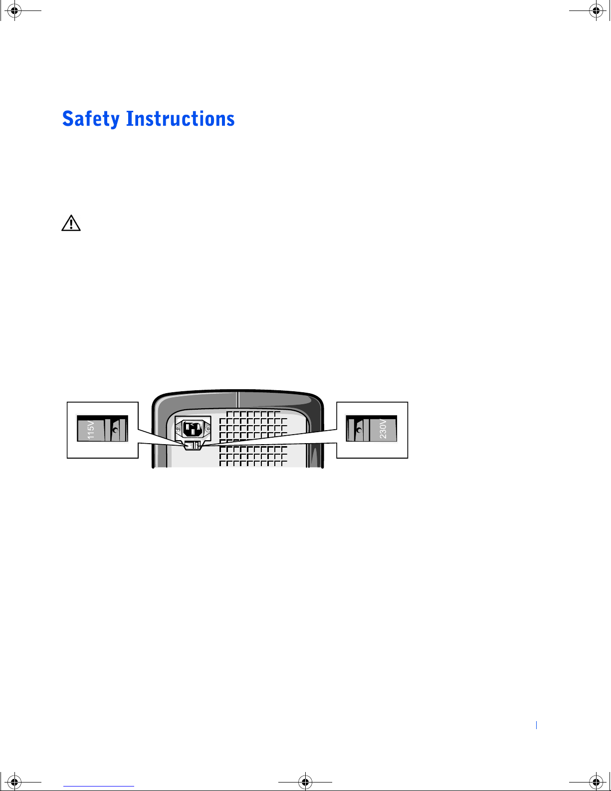
• To help avoid damaging your computer, be sure that the voltage
selection switch is set to match the AC power available at your
location:
– 115 V/60 Hz in most of North and South America and some Far
Eastern countries such as South Korea and Taiwan
– 100 V/50 Hz in eastern Japan and 100 V/60 Hz in western Japan
– 230 V/50 Hz in most of Europe, the Middle East, and the Far East
Also be sure that your monitor and attached devices are electrically
rated to operate with the AC power available in your location.
• To help prevent damage to your computer when disconnecting a
network cable from your computer, first unplug the cable from the
computer network connector and then from the network wall jack.
When reconnecting a network cable to your computer, first plug the
network cable into the network wall jack and then into the computer
network connector.
• To help avoid possible damage to the system board, wait 5 seconds
after turning off the computer before disconnecting or connecting a
non-USB device.
Safety Instructions 7
Page 8

4C381a00.book Page 8 Thursday, June 14, 2001 9:38 AM
• To help prevent electric shock, plug the computer and device power
• To help protect your computer from sudden, transient increases and
• Be sure that nothing rests on your computer cables and that the cables
www.dell.com | support.dell.com
• Do not spill food or liquids on your computer. If the computer gets
cables into properly grounded power sources. These cables are
equipped with 3-prong plugs to help ensure proper grounding. Do not
use adapter plugs or remove the grounding prong from a cable. If you
must use an extension cable, use a 3-wire cable with properly grounded
plugs.
decreases in electrical power, use a surge suppressor, line conditioner,
or uninterruptable power supply.
are not located where they can be stepped on or tripped over.
wet, contact Dell (see page 70).
• Do not push any objects into the openings of your computer. Doing so
can cause fire or electric shock by shorting out interior components.
• Keep your computer away from radiators and heat sources. Also, do not
block cooling vents. Avoid placing loose papers underneath your
computer; do not place your computer in a closed-in wall unit or on a
bed, sofa, or rug.
When Working Inside Your Computer
Before you remove the computer cover, perform the following steps in the
sequence indicated.
NOTICE: Do not attempt to service the computer yourself, except as
explained in this guide and elsewhere in Dell documentation. Always follow
installation and service instructions closely.
Turn off your computer and all devices.
1
2 Ground yourself by touching an unpainted metal surface at the back of
the computer before touching anything inside your computer.
While you work, periodically touch an unpainted metal surface on the
computer to dissipate any static electricity that might harm internal
components.
3 Disconnect any devices connected to the computer, including the
8 Safety Instructions
monitor, from their electrical outlets to reduce the potential for
personal injury or shock. Also, disconnect any telephone or
telecommunication lines from the computer.
Page 9
4C381a00.book Page 9 Thursday, June 14, 2001 9:38 AM
4 Disconnect the power cable from your computer, and then press the
power button to ground the system board.
In addition, take note of these safety guidelines when appropriate:
• When you disconnect a cable, pull on its connector, not on the cable
itself. As you pull connectors apart, keep them evenly aligned to avoid
bending any pins. Also, before you connect a cable, make sure that
both connectors are correctly oriented and aligned.
• Handle components and cards with care. Don’t touch the components
on a card. Hold a card by its edges or by its metal bracket.
CAUTION: There is a danger of a new battery exploding if it is
incorrectly installed. Replace the battery only with the same or
equivalent type recommended by the manufacturer. Discard used
batteries according to the manufacturer instructions.
Protecting Against Electrostatic Discharge
To prevent static damage, discharge static electricity from your body before
you touch anything inside your computer and periodically while you work
inside the computer. You can do so by touching an unpainted metal surface
on the back of the computer.
You can also take the following steps to prevent static damage:
• Do not remove items from their antistatic packing material until you
are ready to install them in your computer. Just before unwrapping the
antistatic packaging, be sure to discharge static electricity from your
body.
• When transporting a sensitive component, first place it in an antistatic
container or packaging.
Safety Instructions 9
Page 10

4C381a00.book Page 10 Thursday, June 14, 2001 9:38 AM
www.dell.com | support.dell.com
10 Safety Instructions
Page 11
4C381a00.book Page 11 Thursday, June 14, 2001 9:38 AM
SECTION 1
Connecting a Printer
Turning Off the Computer
www.dell.com | support.dell.com
Page 12
4C381a00.book Page 12 Thursday, June 14, 2001 9:38 AM
HINT: If you have
problems with your
printer, contact the
printer manufacturer for
assistance.
www.dell.com | support.dell.com
See the documentation that came with the printer for any recommended
preparation procedures, such as:
• Removing the packaging
• Installing the toner or ink cartridge
• Loading paper
Then follow the instructions that came with the printer to connect it to the
computer. If no information is provided, see the following sections.
Parallel Printer
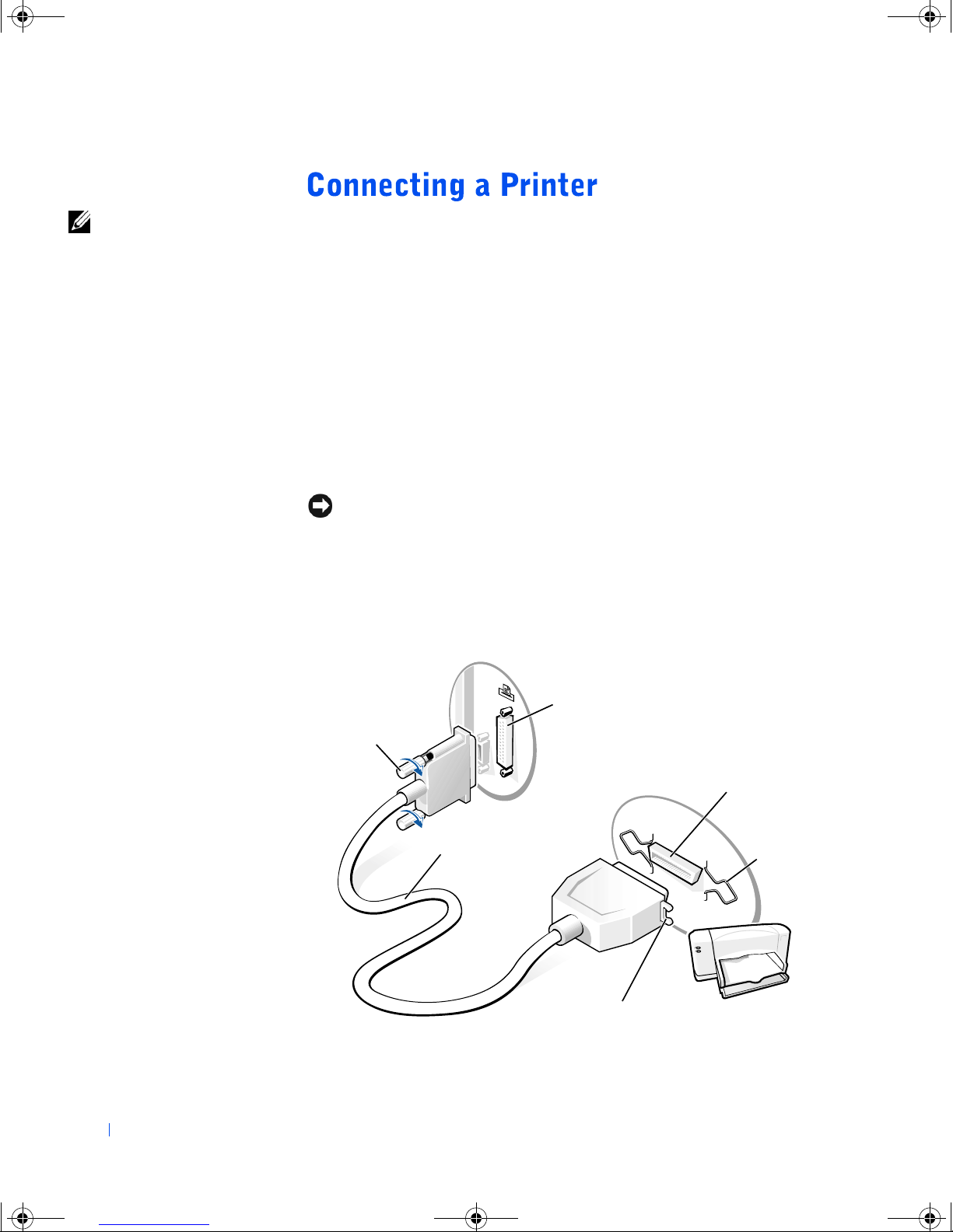
1 Turn off the computer (see page 14).
NOTICE: Use only a standard IEEE parallel cable measuring 10 ft (3 m) or
less to connect the printer to the computer. Use of a nonstandard cable may
prevent the printer from working.
Attach the parallel printer cable to the parallel connector on the
2
computer and tighten the two screws. Attach the cable to the parallel
connector on the printer and snap the two clips into the two notches.
12 Setting Up
screws (2)
parallel printer
cable
parallel connector
on computer
parallel connector
on printer
clips (2)
notches (2)
Page 13
4C381a00.book Page 13 Thursday, June 14, 2001 9:38 AM
3 Turn on the printer and then turn on the computer. If the Add New
Hardware Wizard window appears, click Cancel.
4 Install the printer driver if necessary.
USB Printer
1 Install the printer driver if necessary.
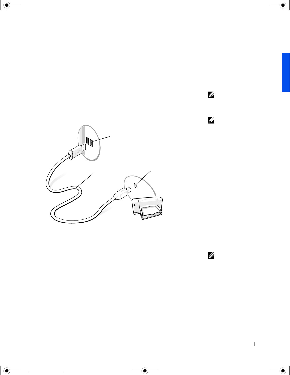
2 Attach the USB printer cable to the USB connector on the computer
and the printer (the USB connectors fit only one way).
USB connectors on front
or back of computer
USB printer
cable
USB connector
on printer
HINT: You can connect
USB devices while the
computer is turned on.
HINT: Your computer has
two USB connectors on
the back side panel and
two USB connectors on
the front side panel (see
the Start Here sheet for
their locations).
Installing the Printer Driver
If you need to install a printer driver, insert the installation CD into the CD
drive. Then follow the prompts on the screen using the instructions that
came with the printer.
If your printer installation CD does not automatically run, click the Start
®
button on the Microsoft
x:\setup.exe (where x is the letter of your CD drive [usually drive D]).
Then click OK and follow the prompts on your screen.
Windows® desktop, click Run, and type
HINT: Dell installs
drivers for some new
printers. Click the Start
button, point to Settings,
and then click Printers. If
your printer is listed in the
Printers window, the
printer is ready to use.
Setting Up 13
Page 14
4C381a00.book Page 14 Thursday, June 14, 2001 9:38 AM
If you connect an older printer and it does not work after you install the
driver, access the system setup program (see page 66) and ensure that the
parallel port is set to operate in bidirectional mode.
Windows 2000
1 Save and close any open files and exit any open programs.
www.dell.com | support.dell.com
2 Click the Start button, and then click Shut Down.
NOTICE: To prevent data loss, you must perform the Windows shutdown
procedure.
3 Click the pull-down menu under What do you want the computer to
do?
4 Click Shut down and then click OK.
5 The computer automatically turns off after the shutdown process
finishes.
6 Turn off your monitor and any other devices connected to power.
Windows Millennium Edition (Me)
1 Save and close any open files and exit any open programs.
2 Click the Start button, and then click Shut Down.
3 In the Shut Down Windows window, click Shut down and then click
OK.
The computer automatically turns off after the shutdown process
finishes.
4 Turn off your monitor and any other devices connected to power.
14 Setting Up
Page 15

4C381a00.book Page 15 Thursday, June 14, 2001 9:38 AM
SECTION 2
Finding Solutions
Accessing Help Files
Power Problems
Start-Up Error Messages
Video and Monitor Problems
Sound and Speaker Problems
Printer Problems
Scanner Problems
Modem Problems
Mouse Problems
Keyboard Problems
Drive Problems
Network Problems
Windows
®
Error Messages
General Program Problems
Internet Connection Problems
www.dell.com | support.dell.com
E-Mail Problems
Resolving Other Technical Problems
Reinstalling Drivers
Reinstalling Windows 2000
Reinstalling Windows Me
Page 16
4C381a00.book Page 16 Thursday, June 14, 2001 9:38 AM
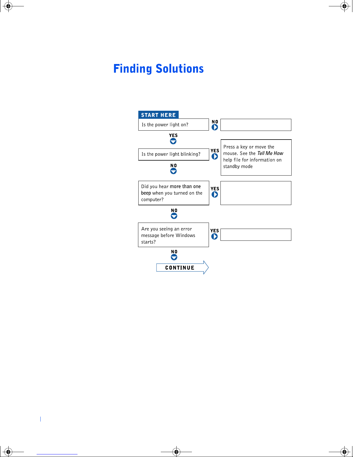
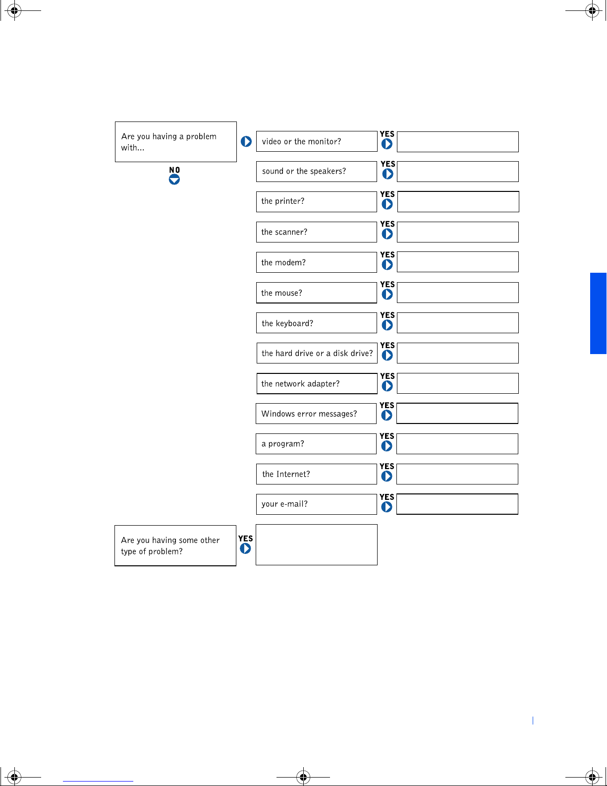
Sometimes it’s difficult to figure out where to go for answers. Use this chart
to help you quickly find the answers to your questions.
www.dell.com | support.dell.com
See page 18.
Get technical assistance
from Dell. See page 70.
See page 19.
16 Solving Problems
Page 17
4C381a00.book Page 17 Thursday, June 14, 2001 9:38 AM
See page 20.
See page 22.
See page 23.
See page 24.
See page 25.
See page 26.
See page 32.
See page 26.
See page 27.
See page 29.
See page 29.
See page 30.
See page 31.
See page 31.
Solving Problems 17
Page 18
4C381a00.book Page 18 Thursday, June 14, 2001 9:38 AM
TO ACCESS THE TELL ME HOW HELP FILE — Click the Start button, point
to Programs—> User’s Guides, and then click Tell Me How.
TO ACCESS MICROSOFT® WINDOWS® 2000 HELP
1 Click the Start button and then click Help.
2 Click the Search tab.
3 Type a word or phrase that describes your problem and then click List Topics.
4 Click the topic that describes your problem and then click Display.
www.dell.com | support.dell.com
5 Follow the instructions shown on the screen.
HINT: See the Tell M e
How help file for
information on standby
mode.
TO ACCESS WINDOWS ME HELP
1 Click the Start button and then click Help.
2 Type a word or phrase that describes your problem in the Search box and then
click Go.
3 Click the topic that describes your problem and then click Display.
4 Follow the instructions shown on the screen.
NOTICE: To help prevent damage to your computer when disconnecting a
network cable from your computer, first unplug the cable from the computer
network connector and then from the network wall jack. When reconnecting a
network cable to your computer, first plug the network cable into the network
wall jack and then into the computer network connector.
CHECK THE POWER LIGHT — When the power light is lit or blinking, the
computer has power. If the power light is blinking, the computer is in standby
mode—press a key on the keyboard or move the mouse to exit standby mode.
TEST THE ELECTRICAL OUTLET — Ensure that the electrical outlet is
working by testing it with another device, such as a lamp.
CHECK THE POWER CABLE CONNECTION — Be sure that the power cable
is firmly inserted into the electrical outlet and the computer power connector.
18 Solving Problems
Page 19
4C381a00.book Page 19 Thursday, June 14, 2001 9:38 AM
CONNECT THE COMPUTER DIRECTLY TO AN ELECTRICAL OUTLET —
Turn off the computer and then bypass power protection devices, power strips,
and the extension cable to verify that the computer turns on.
SWAP THE COMPUTER AND MONITOR POWER CABLES — Turn off the
computer and then swap the computer and monitor power cables to determine if
the power cable is defective.
CHECK FOR INTER FERENCE — Electrical appliances on the same circuit or
operating near the computer can cause interference. Other causes of
interference: power extension cables, keyboard and mouse extension cables, too
many devices on a power strip, or multiple power strips connected to the same
electrical outlet.
CHECK THE POWER PROPERTIES — See the Tell Me How help file or
search for the keyword standby in Windows Help. For instructions on accessing
help files, see page 18.
OPERATING SYSTEM NOT FOUND — Contact Dell (see page 70).
INSERT BOOTABLE MEDIA — The operating system is trying to boot to a
nonbootable floppy disk or CD. Insert a bootable floppy disk or CD.
NON-SYSTEM DISK ERROR — A floppy disk is in the floppy drive. Remove
the floppy disk and restart the computer.
Solving Problems 19
Page 20
4C381a00.book Page 20 Thursday, June 14, 2001 9:38 AM
If the screen is blank
HINT: See the monitor
documentation for fault
indications and
www.dell.com | support.dell.com
troubleshooting
procedures specific to
your monitor.
CHECK THE VIDEO CABLE CONNECTION — Check for bent pins. Ensure
that the video cable is connected as shown on the Start Here sheet for your
computer.
PRESS THE MONITOR POWER BUTTON — Be sure that you firmly pressed
the monitor power button.
NOTICE: To help prevent damage to your computer when disconnecting a
network cable from your computer, first unplug the cable from the computer
network connector and then from the network wall jack. When reconnecting a
network cable to your computer, first plug the network cable into the network
wall jack and then into the computer network connector.
CHECK THE POWER LIGHT — When the monitor power light is lit or
blinking, the monitor has power. If the power light is blinking, the computer is in
standby mode; press a key on the keyboard or move the mouse to exit standby
mode.
TEST THE ELECTRICAL OUTLET — Turn off your computer and then ensure
that the electrical outlet is working by testing it with another device, such as a
lamp.
SWAP THE COMPUTER AND MONITOR POWER CABLES — Turn off your
computer and then swap the computer and monitor power cables to determine if
the power cable is defective.
TEST THE VIDEO EXTENSIO N CABLE (IF USED)— If removing the video
extension cable solves the problem, the cable is defective.
TEST THE MONITOR — If another monitor is available, connect it to the
computer.
CHECK THE BACK PANEL LIGHTS — If all four lights below the serial
connector are not green, contact Dell (see page 70).
20 Solving Problems
Page 21
4C381a00.book Page 21 Thursday, June 14, 2001 9:38 AM
CHECK THE POWER PROPERTIES — See the Tell Me How help file or
search for the keyword standby in Windows Help. For instructions on accessing
help files, see page 18.
If the screen is difficult to read
ADJUST THE CONTRAST AND BRIGHTNESS — See the monitor
documentation for instructions on adjusting the contrast and brightness.
MOVE THE SUBWOOFER AWAY FROM THE MONITOR — If your speaker
system includes a subwoofer, ensure that the subwoofer is at least 60 cm (2 ft)
away from the monitor.
ELIMINATE POSSIBLE INTER FERENCE — Turn off nearby fans, fluorescent
lights, or halogen lamps to check for interference.
ROTATE THE MONITOR TO FACE A DIFFERENT DIRECTION — Eliminate
sunlight glare, which can cause poor picture quality.
DEGAUSS (DEMAGNETIZE) THE MONITOR — See the monitor
documentation.
RUN THE MONITOR SELF- TEST — See the monitor documentation.
RESTORE THE RECOMMENDED SETTINGS — Restore the original
resolution and refresh rate settings. See the Tell Me How help file for instructions.
For instructions on accessing help files, see page 18.
CHECK FOR ADDITIONAL ADJUSTMENTS — See the monitor
documentation for any additional adjustments that your monitor may require.
ADJUST THE WINDOWS DISPLAY SETTINGS — Click the Start button,
point to Settings, and click Control Panel. Double-click the Display icon and
then click the Settings tab. Try different settings for Colors and Screen area.
Solving Problems 21
Page 22
4C381a00.book Page 22 Thursday, June 14, 2001 9:38 AM
HINT: The volume
control in some MP3
players overrides the
Windows volume setting.
If you have been listening
www.dell.com | support.dell.com
to MP3 songs, make sure
that you did not turn the
player volume down or off.
VERIFY THE SPEAKER CABLE CONNECTIONS — Ensure that the speakers
are connected as shown on the Start Here sheet for your computer and the setup
diagram supplied with the speakers.
TEST THE ELECTRICAL OUTLET — Ensure that the electrical outlet is
working by testing it with another device, such as a lamp.
NOTICE: To help prevent damage to your computer when disconnecting a
network cable from your computer, first unplug the cable from the computer
network connector and then from the network wall jack. When reconnecting a
network cable to your computer, first plug the network cable into the network
wall jack and then into the computer network connector.
ENSURE THAT THE SPEAKERS ARE TURNED ON — See the setup
diagram supplied with the speakers.
ADJUST THE SPEAKER CONTROLS — Adjust the volume, bass, or treble
controls to eliminate distortion.
BE SURE HEADPHONES ARE NOT CONNECTED TO THE FRONT- PANEL
INE-OUT CONNECTOR — The speakers are automatically muted when
L
headphones are connected to the line-out connector on the front of the
computer (see the Start Here sheet for the location of the line-out connector).
ADJUST THE WINDOWS VOLUME CONTROL — Double-click the yellow
speaker icon in the lower-right corner of your screen. Be sure that the volume is
turned up and that the sound is not muted.
TEST THE SPEAKERS — Plug the speaker audio cable into the headphone
jack of the CD drive. Ensure that the headphone volume control is turned up.
Play a music CD.
RUN THE SPEAKER SELF- TEST — Some speaker systems have a self-test
button on the subwoofer. See the speaker documentation for self-test
instructions.
22 Solving Problems
Page 23

4C381a00.book Page 23 Thursday, June 14, 2001 9:38 AM
MOVE THE SUBWOOFER AWAY FROM THE MONITOR — If your speaker
system includes a subwoofer, ensure that the subwoofer is at least 60 cm (2 ft)
away from the monitor.
ELIMINATE POSSIBLE INTER FERENCE — Turn off nearby fans, fluorescent
lights, or halogen lamps to check for interference.
REINSTALL THE SOUND (AUDIO) DRIVER — See page 32.
NOTICE: To help prevent damage to your computer when disconnecting a
network cable from your computer, first unplug the cable from the computer
network connector and then from the network wall jack. When reconnecting a
network cable to your computer, first plug the network cable into the network
wall jack and then into the computer network connector.
If you cannot print to a parallel port printer
VERIFY THE PRINTER CABLE CONNECTIONS — Ensure that the printer
cable is connected as described on page 12.
TEST THE ELECTRICAL OUTLET — Ensure that the electrical outlet is
working by testing it with another device, such as a lamp.
ENSURE THAT THE PRINTER IS TURNED ON — See the documentation
supplied with the printer.
VERIFY THAT THE PRINTER IS RECOGNIZED BY WINDOWS
1 Click the Start button, point to Settings, and then click Printers.
If the printer is listed, right-click the printer icon, click Properties, and then
select the Details tab.
2 Ensure that the Print to the following port: setting is LPT1 (Printer Port).
REINSTALL THE PRINTER DRIVER — See page 13.
Solving Problems 23
Page 24
4C381a00.book Page 24 Thursday, June 14, 2001 9:38 AM
If you cannot print to a USB printer
VERIFY THE PRINTER CABLE CONNECTIONS — Ensure that the printer
cable is connected as described on page 13.
TEST THE ELECTRICAL OUTLET — Ensure that the electrical outlet is
working by testing it with another device, such as a lamp.
ENSURE THAT THE PRINTER IS TURNED ON — See the documentation
supplied with the printer.
www.dell.com | support.dell.com
VERIFY THAT THE PRINTER IS RECOGNIZED BY WINDOWS — Click the
Start button, point to Settings, and then click Printers. If the printer is listed,
right-click the printer icon, click Properties, and then select the Details tab.
REINSTALL THE PRINTER DRIVER — See page 13.
NOTICE: To help prevent damage to your computer when disconnecting a
network cable from your computer, first unplug the cable from the computer
network connector and then from the network wall jack. When reconnecting a
network cable to your computer, first plug the network cable into the network
wall jack and then into the computer network connector.
CHECK THE POWER CABLE CONNECTION — Ensure that the scanner
power cable is firmly connected to a working electrical power source and that the
scanner is turned on.
CHECK THE SCANNER CABLE CONNECTION — Ensure that the scanner
cable is firmly connected to the computer and to the scanner.
UNLOCK THE SCANNER — Ensure that your scanner is unlocked if it has a
locking tab or button.
REINSTALL THE SCANNER DRIVER — Reinstall the scanner driver. See the
scanner documentation for instructions.
24 Solving Problems
Page 25
4C381a00.book Page 25 Thursday, June 14, 2001 9:38 AM
NOTICE: Connect the modem to an analog telephone jack only. Connecting
the modem to a digital telephone network damages the modem.
CHECK THE TELEPHONE JACK — Disconnect the telephone line from the
modem and connect it to a telephone. Listen for a dial tone.
CONNECT THE MODEM DIRECTLY TO THE TELEPHONE WALL JACK —
If you have other telephone devices sharing the line, such as an answering
machine, fax machine, surge protector, or line splitter, then bypass them and
connect the modem directly to the telephone wall jack with the telephone
line. —
CHECK THE CONNECTION — Verify that the telephone line is connected to
the green jack on the modem. (The green line-in jack has either a LINE IN label
or a connector-shaped icon next to it.)
CHECK THE TELEPHONE LINE — Try using a different telephone line. If you
are using a line that is 3 m (10 ft) or more in length, try a shorter one.
VERIFY THAT THE MODEM IS COMMUNICATING WITH WINDOWS
1 Click the Start button, point to Settings, and click Control Panel.
2 In the Control Panel, double-click Modems.
If there are multiple entries for the same modem or modems listed that are
not installed, delete the entries and restart the computer.
3 Click the Diagnostics tab.
4 Click the COM port for your modem.
5 Click More Info to verify that the modem is communicating with Windows.
If all commands receive responses, the modem is operating properly.
Solving Problems 25
Page 26
4C381a00.book Page 26 Thursday, June 14, 2001 9:38 AM
If the mouse does not respond
RECONNECT THE MOUSE CABLE
1 Press <Ctrl><Esc> to display the Start menu.
2 Press the arrow keys to highlight Shut Down and then press <Enter>.
3 Disconnect the mouse cable from the computer.
4 Reconnect the mouse cable as shown on the Start Here sheet for your
www.dell.com | support.dell.com
5 Turn on the computer.
If the computer has stopped responding, press the power button until the
computer turns off.
computer.
CHECK THE MOUSE SETTINGS — Click the Start button, select Control
Panel, and then double-click the Mouse icon. Try adjusting the settings.
CLEAN THE MOUSE — If the pointer doesn’t move on the screen when you
move the mouse, or if the mouse stops responding, remove the mouse ball by
unscrewing the cover located on the bottom of the mouse. Clean the ball and
rollers, and then replace the mouse ball and cover. See the Tell Me How help file
for more detailed instructions. For instructions on accessing help files, see
page 18.
RESTART THE COMPUTER — The computer may have stopped responding.
Press and hold the power button until the computer turns off, and then press the
power button again to turn the computer on.
RECONNECT THE KEYBOARD CABLE — Shut down the computer (see
page 14), reconnect the keyboard cable as shown on the
Start Here sheet for
your computer, and then restart the computer.
26 Solving Problems
Page 27
4C381a00.book Page 27 Thursday, June 14, 2001 9:38 AM
If you cannot save a file to a floppy disk
ENSURE THAT WINDOWS RECOGNIZES THE DRIVE — Double-click the
My Computer icon. If the floppy drive is not listed, perform a full scan with your
antivirus software to check for and remove viruses. Viruses can sometimes
prevent Windows from recognizing the drive.
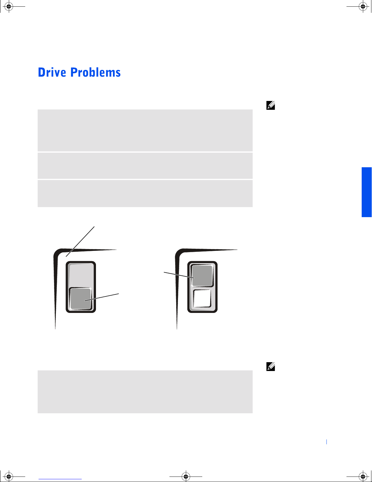
CANNOT SAVE FILES TO A FLOPPY DISK — Ensure that the floppy disk is
not full or write-protected (locked). See the following illustration.
HINT: For information
on saving files to a floppy
disk, see the Tell Me How
help file. For instructions
on accessing help files, see
page 18.
TEST THE DRIVE WITH ANOTHER FLOPPY DISK — Insert another floppy
disk to eliminate the possibility that the original floppy disk is defective.
back of floppy disk
write-protected
not writeprotected
If you cannot play a music CD or install a program from a CD
ENSURE THAT WINDOWS RECOGNIZES THE DRIVE — Double-click the
My Computer icon. If the CD drive is not listed, perform a full scan with your
antivirus software to check for and remove viruses. Viruses can sometimes
prevent Windows from recognizing the drive.
HINT: High-speed CD
drive vibration is normal
and may cause noise. This
noise does not indicate a
defect in the drive or the
CD.
Solving Problems 27
Page 28
4C381a00.book Page 28 Thursday, June 14, 2001 9:38 AM
TEST THE DRIVE WITH ANOTHER CD — Insert another CD to eliminate
the possibility that the original CD is defective.
CLEAN THE DISC — See the Tell Me How help file for instructions. For
instructions on accessing help files, see page 18.
ADJUST THE WINDOWS VOLUME CONTROL — Double-click the yellow
speaker icon in the lower-right corner of your screen. Be sure that the volume is
turned up and that the sound is not muted.
www.dell.com | support.dell.com
HINT: Because of
different worldwide file
types, not all DVD titles
work in all DVD drives.
HINT: If you disable
standby mode to write to a
CD-RW drive, remember
to reenable standby mode
when you finish writing
the CD.
If you cannot play a DVD movie
ENSURE THAT WINDOWS RECOGNIZES THE DRIVE — Double-click the
My Computer icon. If the DVD drive is not listed, perform a full scan with your
antivirus software to check for and remove viruses. Viruses can sometimes
prevent Windows from recognizing the drive.
TEST THE DRIVE WITH ANOTHER DVD — Insert another DVD to
eliminate the possibility that the original DVD is defective.
CLEAN THE DISC — See the Tell Me How help file for instructions. For
instructions on accessing help files, see page 18.
If the CD-RW drive stops writing
DISABLE STANDBY MODE IN WINDOWS BEFORE WRITING TO A
CD-RW — Search for the keyword standby in Windows Help. For instructions
on accessing help files, see page 18.
CHANGE THE WRITE SPEED TO A SLOWER RATE — See the help files for
your CD creation software.
CLOSE ALL OTHER OPEN PROGRAMS — Closing all other open programs
before writing to the CD-RW may alleviate the problem.
28 Solving Problems
Page 29
4C381a00.book Page 29 Thursday, June 14, 2001 9:38 AM
If you have a hard drive problem
RUN SCAND ISK — Click the Start button, point to Programs—>
Accessories—> System Tools, and then click ScanDisk.
NOTICE: To help prevent damage to your computer when disconnecting a
network cable from your computer, first unplug the cable from the computer
network connector and then from the network wall jack. When reconnecting a
network cable to your computer, first plug the network cable into the network
wall jack and then into the computer network connector.
CHECK THE NETWORK CABLE CONNECTOR — Ensure that the network
cable connector is firmly connected to the connector on the computer and the
network wall jack as shown on the Start Here sheet for your computer.
RESTART THE COMPUTER — Try to log on to the network again.
CONTACT YOUR NETWORK ADMINISTRATOR — Verify that your network
settings are correct and that the network is functioning.
®
X :\ IS NOT ACCESSIBLE. THE DEVICE IS NOT READY — Insert a disk
into the drive and try again.
A FILENAME CANNOT CONTAIN ANY OF THE FOLLOWING
CHARACTERS: \ / : * ? “< > | — Do not use these characters in
filenames.
NOT ENOUGH MEMORY OR RESOURCES. CLOSE SOME PROGRAMS AND
TRY AGAIN — You have too many programs open. Close all windows, restart
the computer, and then open the program that you want to use.
Solving Problems 29
Page 30
4C381a00.book Page 30 Thursday, June 14, 2001 9:38 AM
THE FILE BEING COPIED IS TOO LARGE FOR THE DESTINATION
DRIVE — The file that you are trying to copy is too large to fit on the disk. Try
copying the file to a blank disk or use a larger capacity disk.
A REQUIRED .DLL FILE WAS NOT FOUND — The program that you are
trying to open is missing an essential file. To remove and then reinstall the
program:
1 Click the Start button, point to Settings, and then click Control Panel.
2 Double-click the Add/Remove Programs icon.
3 Select the program that you want to remove.
4 Click Add/Remove (or Change/Remove in Windows 2000) and follow the
www.dell.com | support.dell.com
5 See the program documentation for installation instructions.
prompts on the screen.
A program crashes
SEE THE SOFTWARE DOCUMENTATION — Many software manufacturers
maintain websites with information that may help you to solve the problem.
A program stops responding
PRESS <CTRL><ALT><DEL>
1 If necessary, click Task Manager. When the Close Program window appears,
click the name of the program that is no longer responding.
2 Click End Task.
3 Restart the computer.
A solid blue screen appears
TURN THE COMPUTER OFF — If the monitor screen is blue or the computer
stops responding, press the power button until the computer turns off. Press the
power button again to turn on the computer. ScanDisk may run during Windows
start-up. Follow the instructions on the screen.
30 Solving Problems
Page 31
4C381a00.book Page 31 Thursday, June 14, 2001 9:38 AM
REVIEW “MODEM PROBLEMS”—See page 25.
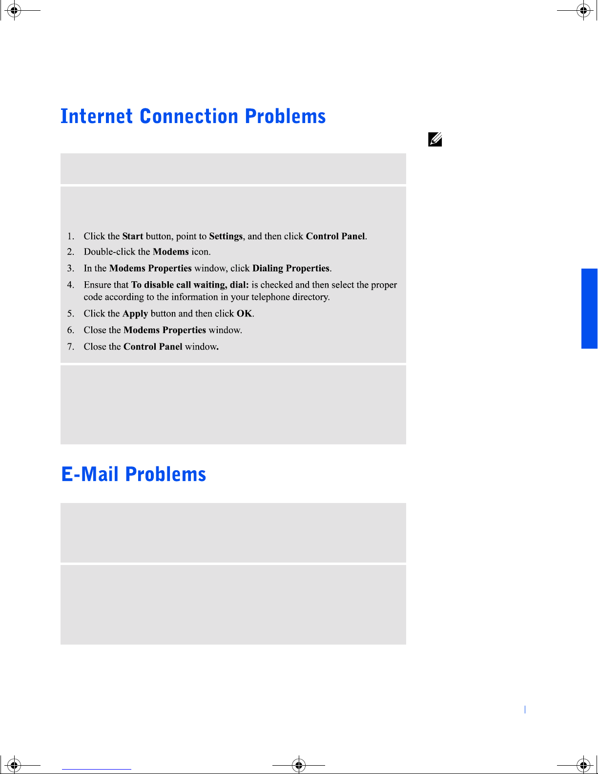
TURN OFF CALL WAITING (CATCH-PHONE)— See your telephone
directory for instructions on deactivating this feature. Then adjust the dial-up
networking connection properties:
HINT: To set up a LAN,
cable, or DSL connection,
double-click the Internet
Explorer icon to start the
Internet Connection
Wizard.
START THE INTERNET CONNECTION WIZARD — If you did not set up
your Internet connection the first time that you turned on the computer, doubleclick the Internet Explorer icon to launch the Internet Connection Wizard and
follow the instructions on the screen. You must have an Internet service provider
(ISP) to access the Internet or send and receive e-mail.
ENSURE THAT YOUR COMPUTER IS CONNECTED TO THE INTERNET —
Open Outlook Express, click File. If Work Offline has a check next to it, click the
check to connect to the Internet.
L AUNCH THE INTERNET CONNECTION WIZARD — If you did not set up
your Internet connection during initial system setup, double-clicking the
Internet Explorer icon launches the Internet Connection Wizard. The wizard
prompts you to set up the software to work with your modem. You must have an
ISP in order to access the Internet or send and receive e-mail.
Solving Problems 31
Page 32
4C381a00.book Page 32 Thursday, June 14, 2001 9:38 AM
GO TO THE DELL SUPPORT WEBSITE — Go to http://support.dell.com for
help with general usage, installation, and troubleshooting questions.
E-MAIL DELL — Go to http://support.dell.com and then click E-Mail Dell in
the Communicate list. Send an e-mail message to Dell about your problem; you
can expect to receive an e-mail message from Dell within hours.
CONTACT DELL — If you cannot solve your problem using the Dell support
www.dell.com | support.dell.com
website or e-mail service, contact Dell (see page 70).
NOTICE: The Dell support website, http://support.dell.com, and the Dell
Dimension ResourceCD provide approved drivers for Dell™ computers. If you
install drivers obtained from other sources, your computer might not work
correctly.
Dell installed the following drivers on your computer:
• Graphics driver — Enables the video controller.
• Audio driver — Enables the sound controller.
• Other drivers — Control devices, such as the modem, sound, and
video cards that might be installed in your computer. For information
on those drivers, click the Start button, point to Programs
—>
User's Guides, and click the appropriate guide from the list.
Sometimes you can fix a device problem by reinstalling its driver:
1 Save and close any open files and exit any open programs.
2 Insert the Dell Dimension ResourceCD into the CD drive.
If this is your first time using the ResourceCD, go to step 3. If not, go
to step 6.
3 When the ResourceCD Installation program starts, follow the
instructions on the screen.
4 When the InstallShield Wizard Complete window appears, remove
32 Solving Problems
the ResourceCD and click Finish to restart the computer.
Page 33
4C381a00.book Page 33 Thursday, June 14, 2001 9:38 AM
5 When you see the Windows desktop, reinsert the ResourceCD into the
CD drive.
6 At the Welcome Dell System Owner screen, click Next.
Please wait... the ResourceCD is detecting hardware
The
in your computer
message appears.
The drivers that are used by your computer are automatically displayed
in the My Drivers—The ResourceCD has identified these
components in your system window.
7 Click the name of the driver that you want to reinstall and follow the
prompts on the screen.
If a particular driver is not listed, then that driver is not required by
your operating system.
To view other contents on the ResourceCD:
1 Be sure your computer is selected in the System Model list.
2 Be sure your operating system is selected in the Operating System list.
3 Select the type of device in the Device Type list.
NOTICE: The Dell Dimension ResourceCD contains drivers for devices that
are not part of your computer. Only reinstall the specific drivers for hardware
included in your computer. Otherwise your computer might not work correctly.
Select a topic in the Topic list.
4
If you select Drivers in the Topic list and a particular driver is not
listed, then that driver is not required by your operating system.
1 Insert the Operating System CD into the CD drive.
2 Shut down the computer (see page 14).
3 Turn on the computer.
4 Press any key when the Press any key to boot from CD message
appears on the screen.
5 When the Windows 2000 Setup screen appears, ensure that the To
setup Win2000 now, press ENTER option is highlighted. Then press
<Enter>.
Solving Problems 33
Page 34

4C381a00.book Page 34 Thursday, June 14, 2001 9:38 AM
6 Read the information in the License Agreement screen, and then press
7 When the Windows 2000 Professional Setup screen appears, press the
8 When the Windows 2000 Professional Setup screen reappears, press
9 Press <Enter> again to restart your computer.
<F8> to continue.
arrow keys to select the Windows 2000 partition option that you want.
To continue, press the key specified in the partition option that you
chose.
the arrow keys to select the type of filing system that you want
Windows 2000 to use, and then press <Enter>.
www.dell.com | support.dell.com
10 Click Next when the Welcome to the Windows 2000 Setup Wizard
screen appears.
11 When the Regional Settings screen appears, select the settings for
your locale, and then click Next.
12 Type your name and organization in the Personalize Your Software
screen, and then click Next.
13 When prompted, type the Windows product key, which is printed on
the Microsoft label on your computer. Then click Next.
14 When the Computer Name and Administrator Password screen
appears, type a name for your computer and a password, if desired.
Then click Next.
15 Enter the date and time in the Date and Time Settings screen, and
then click Next.
Windows 2000 installation begins.
16 When the Completing the Windows 2000 Setup Wizard screen
appears, remove the CD from the drive, and then click Finish.
17 The computer automatically restarts.
34 Solving Problems
Page 35
4C381a00.book Page 35 Thursday, June 14, 2001 9:38 AM
NOTICE: The Operating System CD provides options for reinstalling your
Windows Me operating system. The options can potentially overwrite files
installed by Dell and possibly affect programs installed on your hard drive.
Therefore, Dell does not recommend that you reinstall your operating system
unless instructed to do so by a Dell technical support representative.
NOTICE: To prevent conflicts with Windows Me, you must disable any virus
protection software installed on your computer before you reinstall Windows
Me.
Turn on the computer and access the system setup program as directed
1
by a Dell technical support representative. See page 70 for contact
information.
2 In the system setup program Boot menu, write down the boot
sequence, and then change it so that the CD drive boots first. Then
place the Operating System CD in the CD drive and close the drive
tray.
3 Exit the system setup program.
4 Select Boot From CD-ROM, and then press <Enter>.
If you wait too long to make this selection, the computer automatically
boots from the hard drive. If this occurs, allow the computer to boot
completely, and then restart it and try again.
5 Select Start Windows Setup from CD-ROM, and then press
<Enter>.
6 Press <Enter> again.
7 Select Continue Setup and replace your current operating system,
and then press <Enter>.
8 Press <Enter> again.
ScanDisk automatically starts and checks your hard drive.
9 Click Next in the Welcome to Windows Me window.
10 Select the directory in which Windows resides.
Solving Problems 35
Page 36

4C381a00.book Page 36 Thursday, June 14, 2001 9:38 AM
11 If c:\windows (recommended) is displayed, select it, and then click
12 Ensure that Typical is selected, and then click Next.
13 Specify a computer name, workgroup, and computer description, if
14 Select a country in the Country/Region window, and then click Next.
15 Specify a time zone in the Establish Time Zone window, and then
www.dell.com | support.dell.com
16 Click Finish.
Next.
If
c:\windows.000 (recommended) is displayed, click Other,
change c:\windows.000 to c:\windows, and then click Next.
desired, and then click Next.
click Next.
Windows Setup installs necessary files, and then restarts the computer.
17 Select Boot From Hard Drive, and then press <Enter>.
18 In the User Information window, type your name and, if applicable,
company name, and then click Next.
The Name field must be completed; the Company Name field is
optional.
The License Agreement window appears.
19 Click I accept the Agreement, and then click Next.
20 Type the Windows product key in the fields provided, and then click
Next.
The product key is the bar code number found on the Microsoft
Windows label, which is located on the side of your computer.
21 Click Finish.
Windows Setup installs additional files, and then restarts the
computer.
22 Select Boot From Hard Drive, and then press <Enter>.
23 Select Boot From Hard Drive, and then press <Enter>.
36 Solving Problems
Windows Setup installs additional files, and then restarts the
computer.
Page 37

4C381a00.book Page 37 Thursday, June 14, 2001 9:38 AM
24 Type a password in the Enter Network Password window, if desired,
and then click Next.
25 Remove the Operating System CD from the CD drive.
26 Access the system setup program as directed by a Dell technical
support representative (see page 70.)
27 In the system setup program Boot menu, change the boot sequence
back to the original boot sequence. Then, exit the system setup
program.
Solving Problems 37
Page 38

4C381a00.book Page 38 Thursday, June 14, 2001 9:38 AM
www.dell.com | support.dell.com
38 Solving Problems
Page 39
4C381a00.book Page 39 Thursday, June 14, 2001 9:38 AM
SECTION 3
Opening the Computer Cover
Looking Inside Your Computer
Adding Cards
Removing Cards
Adding Memory
Replacing the AGP Card
Adding a Second Hard Drive
Adding Other Drives
Closing the Computer Cover
www.dell.com | support.dell.com
Page 40
4C381a00.book Page 40 Thursday, June 14, 2001 9:38 AM
1
2
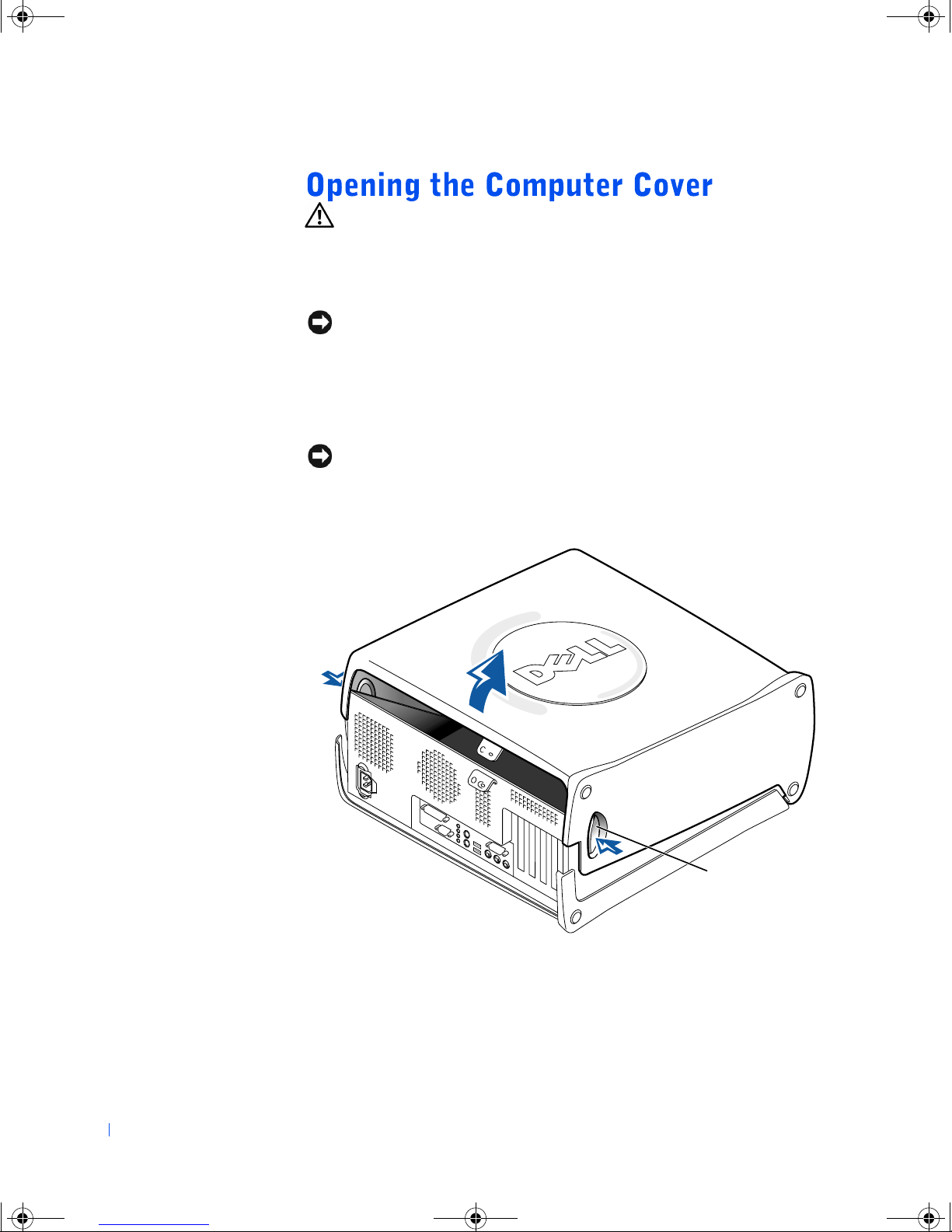
3 Lay the computer on its side so that the arrow on the bottom of the
www.dell.com | support.dell.com
CAUTION: Before you begin any of the procedures in this section,
follow the safety instructions on page 7.
Turn off the computer and any attached devices, and disconnect them
from their electrical outlets.
NOTICE: To disconnect a network cable, first unplug the cable from your
computer and then unplug it from the network wall jack.
Briefly press the power button.
computer points up.
NOTICE: Ensure that there is sufficient space to support the open cover—at
least 30 cm (1 ft) of desk top space.
4
Press the two release buttons and lift the cover.
release buttons (2)
40 Adding Parts
Page 41
4C381a00.book Page 41 Thursday, June 14, 2001 9:38 AM
CAUTION: Before you begin any of the procedures in this section,
follow the safety instructions on page 7.
NOTICE: Be careful when opening the computer cover to ensure that you do
not inadvertently disconnect cables from the system board.
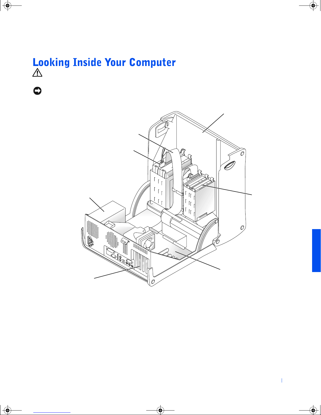
drive cables
power cables
computer cover*
power supply
filler brackets for empty
card-cage slots (4)
* Depending on the types of drives installed in your computer, the cover
hard drive
system board
may not open as widely as shown in the figure.
Adding Parts 41
Page 42
4C381a00.book Page 42 Thursday, June 14, 2001 9:38 AM
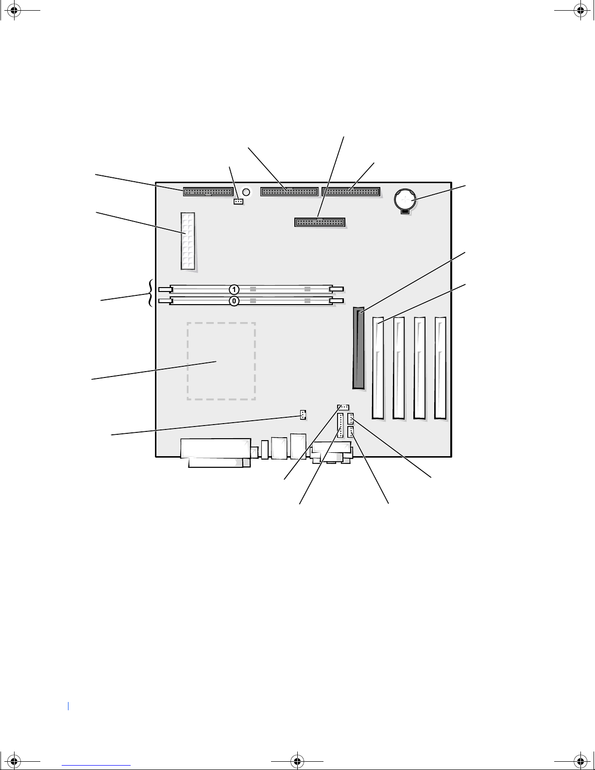
System Board
CD drive connector
floppy drive
connector
main power
connector
recovery jumper
power switch and front panel connector
for Dell Solutions Center button
hard drive connector
battery socket
www.dell.com | support.dell.com
memory module
connectors
microprocessor
connector
microprocessor
fan connector
front panel audio cable connector
1
Accommodates an optional graphics performance accelerator (GPA) card on computers with integrated AGP
2
On computers with the optional telephony modem
CD audio connector
AGP slot
connector
PCI slot
connectors (4)
telephony voice
modem connector
auxiliary line-in connector
1
2
42 Adding Parts
Page 43
4C381a00.book Page 43 Thursday, June 14, 2001 9:38 AM
CAUTION: Before you begin any of the procedures in this section,
follow the safety instructions on page 7.
CAUTION: To guard against electrical shock, always unplug your
computer from the electrical outlet before opening the cover.
1
Turn off the computer and any attached devices, and disconnect them
from their electrical outlets.
NOTICE: To disconnect a network cable, first unplug the cable from your
computer and then unplug it from the network wall jack.
2
Press the power button.
3 Open the computer cover (see page 40).
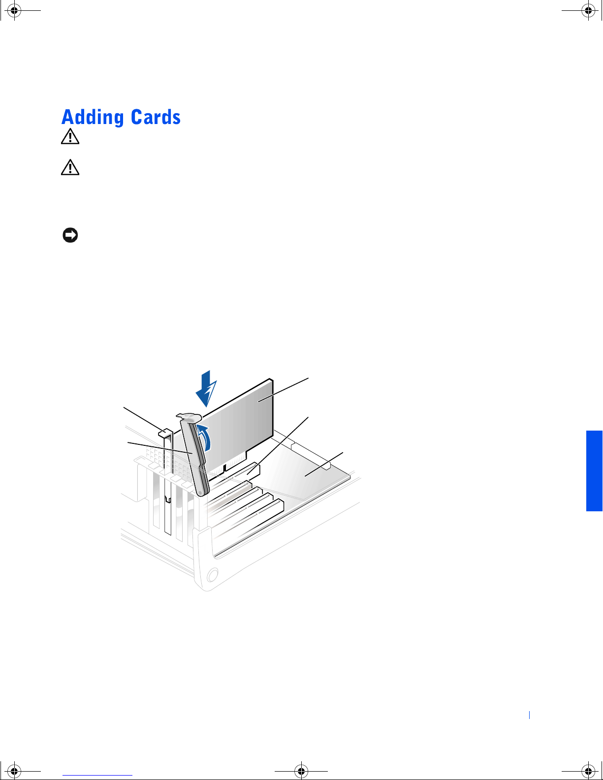
4 To raise the securing lever, press the tab until it is free from the latch
and then lift the lever.
5 Insert the card into the connector.
card
card bracket
slot connector
securing lever
system board
Adding Parts 43
Page 44
4C381a00.book Page 44 Thursday, June 14, 2001 9:38 AM
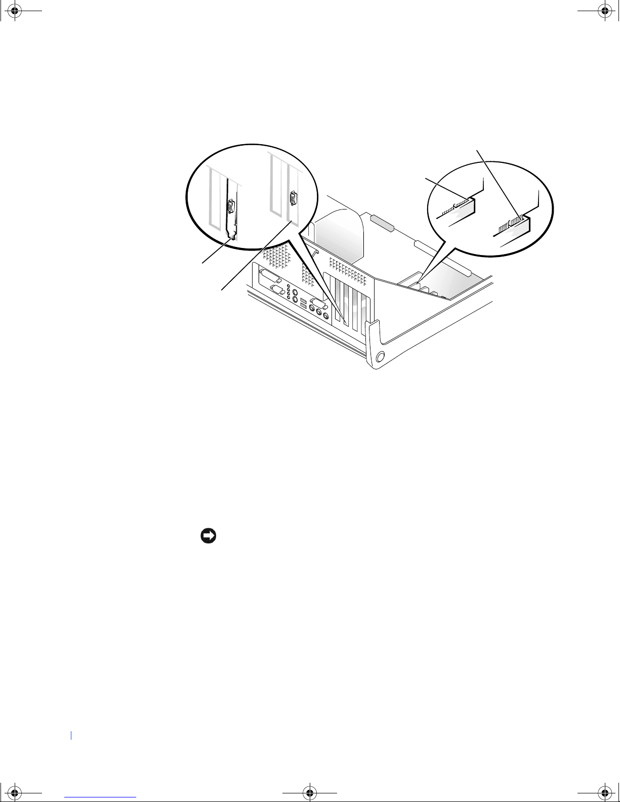
6 Ensure that the card is fully seated in the connector.
bracket caught
outside of slot
not fully seated
fully seated
www.dell.com | support.dell.com
bracket within slot
7 Lower the plastic securing lever.
8 Connect any cables that should be attached to the card.
See the card documentation for information about the card cable
connections.
9 Close the computer cover (see page 59).
10 Connect your computer and devices to their electrical outlets, and
turn them on.
NOTICE: To connect a network cable, first plug the cable in to the network
wall jack and then plug it in to the computer.
11
Install any drivers required for the card as described in the card
documentation.
44 Adding Parts
Page 45
4C381a00.book Page 45 Thursday, June 14, 2001 9:38 AM
CAUTION: Before you begin any of the procedures in this section,
follow the safety instructions on page 7.
1
Turn off the computer and any attached devices, and disconnect them
from their electrical outlets.
NOTICE: To disconnect a network cable, first unplug the cable from your
computer and then unplug it from the network wall jack.
Press the power button.
2
3 Open the computer cover (see page 40).
4 If necessary, disconnect any cables connected to the card.
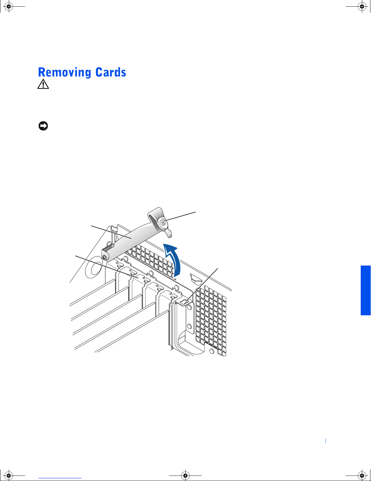
5 To raise the securing lever, press the tab until it is free from the latch
and then lift the lever.
securing lever
card
bracket
tab
latch
Adding Parts 45
Page 46
4C381a00.book Page 46 Thursday, June 14, 2001 9:38 AM
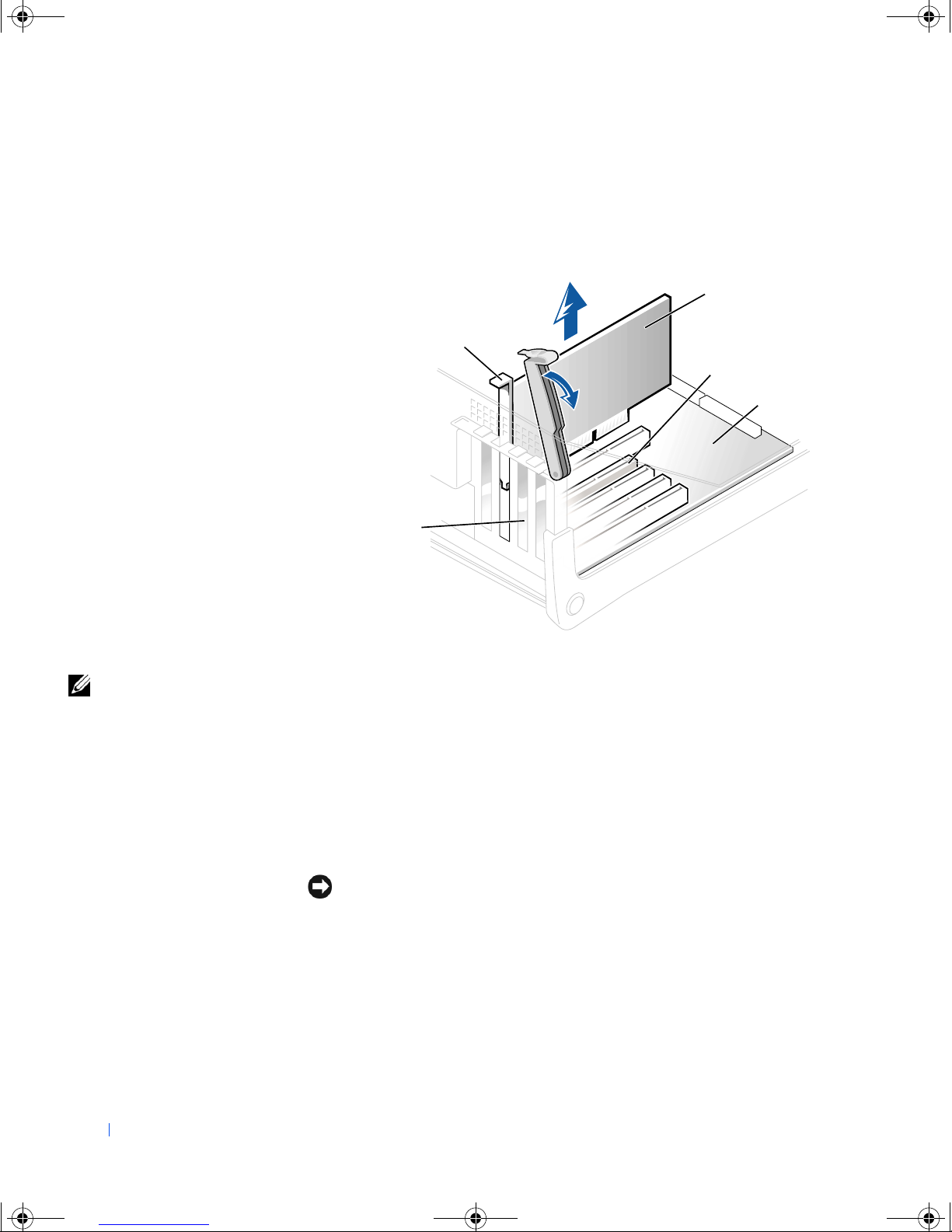
6 To remove the card, grasp the card by the top corners and lift it out.
www.dell.com | support.dell.com
If the card is difficult to remove, gently ease the card back and forth to
remove it from the connector.
card
securing lever
slot connector
system board
HINT: Installing filler
brackets over empty cardslot openings is necessary
to maintain Federal
Communications
Commission (FCC)
certification of the
computer. The brackets
also keep dust and dirt out
of your computer.
filler bracket in empty
card-slot opening
If you are not replacing the card, install a filler bracket in the empty
7
card-slot opening.
If you are adding a card, see page 43.
8 Lower the securing lever.
9 Close the computer cover (see page 59).
10 Connect your computer and devices to their electrical outlets, and
turn them on.
NOTICE: To connect a network cable, first plug the cable in to the network
wall jack and then plug it in to the computer.
46 Adding Parts
Page 47
4C381a00.book Page 47 Thursday, June 14, 2001 9:38 AM
CAUTION: Before you begin any of the procedures in this section,
follow the safety instructions on page 7.
You can increase your computer memory by installing memory modules on
the system board. For information on the type of memory supported by your
computer, see page 62.
Turn off the computer and any devices, and disconnect them from
1
their electrical outlets.
NOTICE: To disconnect a network cable, first unplug the cable from your
computer and then unplug it from the network wall jack.
Press the power button.
2
3 Open the computer cover (see page 40).
4 If necessary, remove a memory module:
a Press out the securing clip at each end of the memory module
connector.
b Grasp the module and pull up.
If the module is difficult to remove, gently ease the module back
and forth to remove it from the connector.
HINT: Memory
purchased from Dell is
covered under your
computer warranty.
Adding Parts 47
Page 48
4C381a00.book Page 48 Thursday, June 14, 2001 9:38 AM
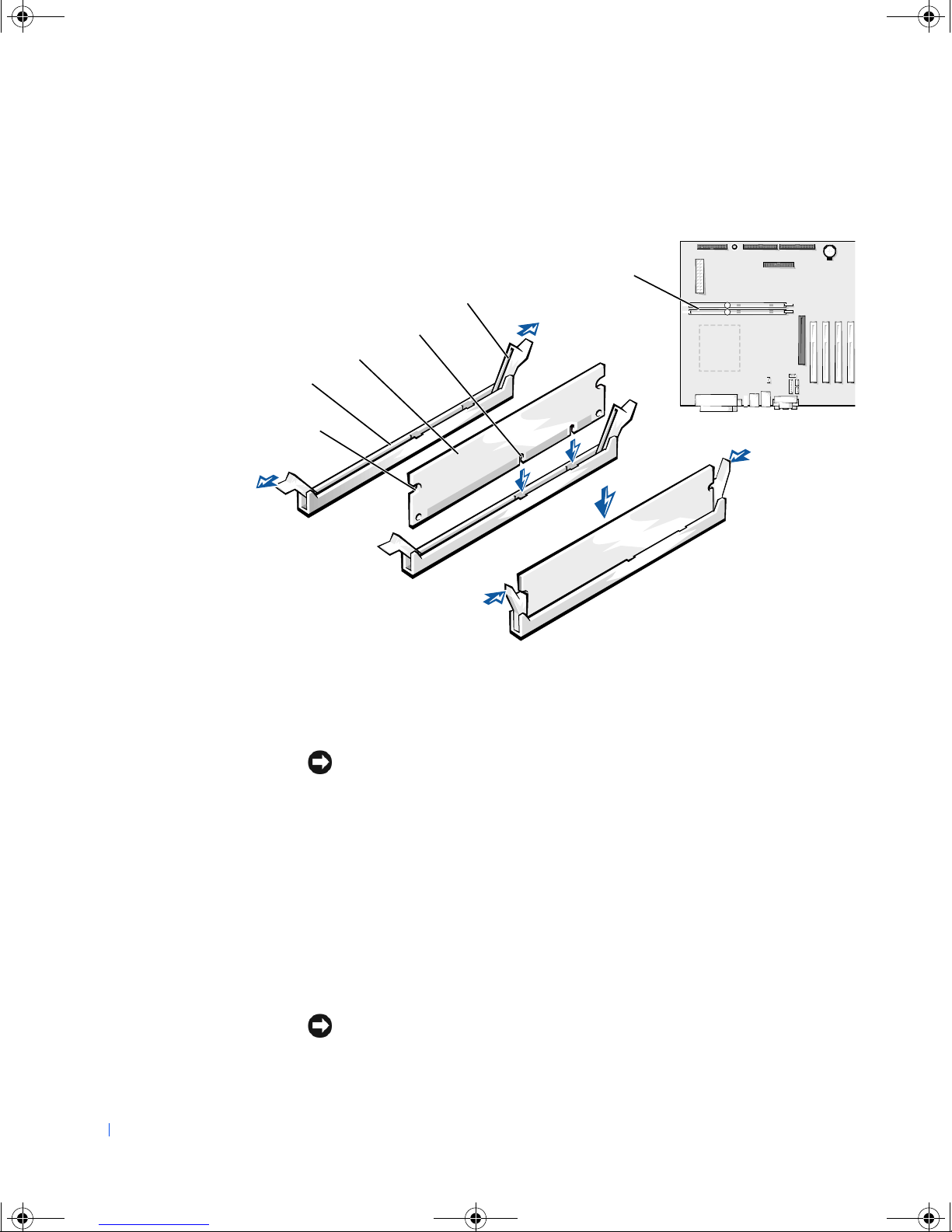
5 To insert a module, press out the securing clip at each end of the
memory module connector.
memory module
connectors
memory module
connector
www.dell.com | support.dell.com
cutouts (2)
securing clips (2)
1
0
notches (2)
step 5
step 6
step 7
6 Align the notches on the bottom of the module with the crossbars in
the connector.
48 Adding Parts
NOTICE: To avoid breaking the memory module, do not press near the middle
of the module.
7
Insert the module straight down into the connector, ensuring that it
fits into the vertical guides at each end of the connector. Press firmly
on the ends of the module until it snaps into place.
If you insert the module correctly, the securing clips snap into the
cutouts at each end of the module.
8 Close the computer cover (see page 59).
9 Connect your computer and devices to their electrical outlets, and
turn them on.
NOTICE: To connect a network cable, first plug the cable in to the network
wall jack and then plug it in to the computer.
Page 49
4C381a00.book Page 49 Thursday, June 14, 2001 9:38 AM
10 Right-click the My Computer icon and then click Properties
11 Click the General tab.
12 To verify that the memory is installed correctly, check the amount of
memory (RAM) listed.
CAUTION: Before you begin any of the procedures in this section,
follow the safety instructions on page 7.
Turn off the computer and any attached devices, and disconnect them
1
from their electrical outlets. Open the computer cover (see page 40).
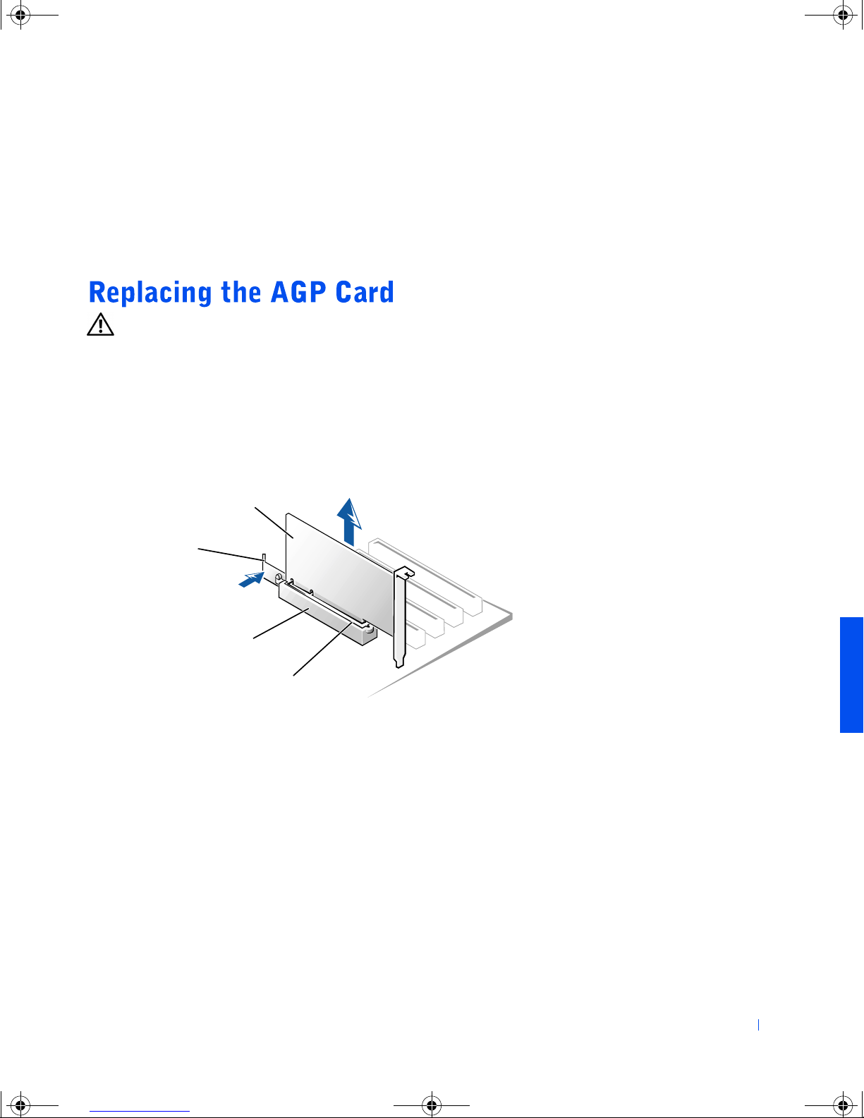
2 Press the card clip lever on the side of the accelerated graphics port
(AGP) card to release the card from the slot connector, and remove the
card.
AGP card
card clip
lever
AGP card clip
slot connector
Adding Parts 49
Page 50
4C381a00.book Page 50 Thursday, June 14, 2001 9:38 AM
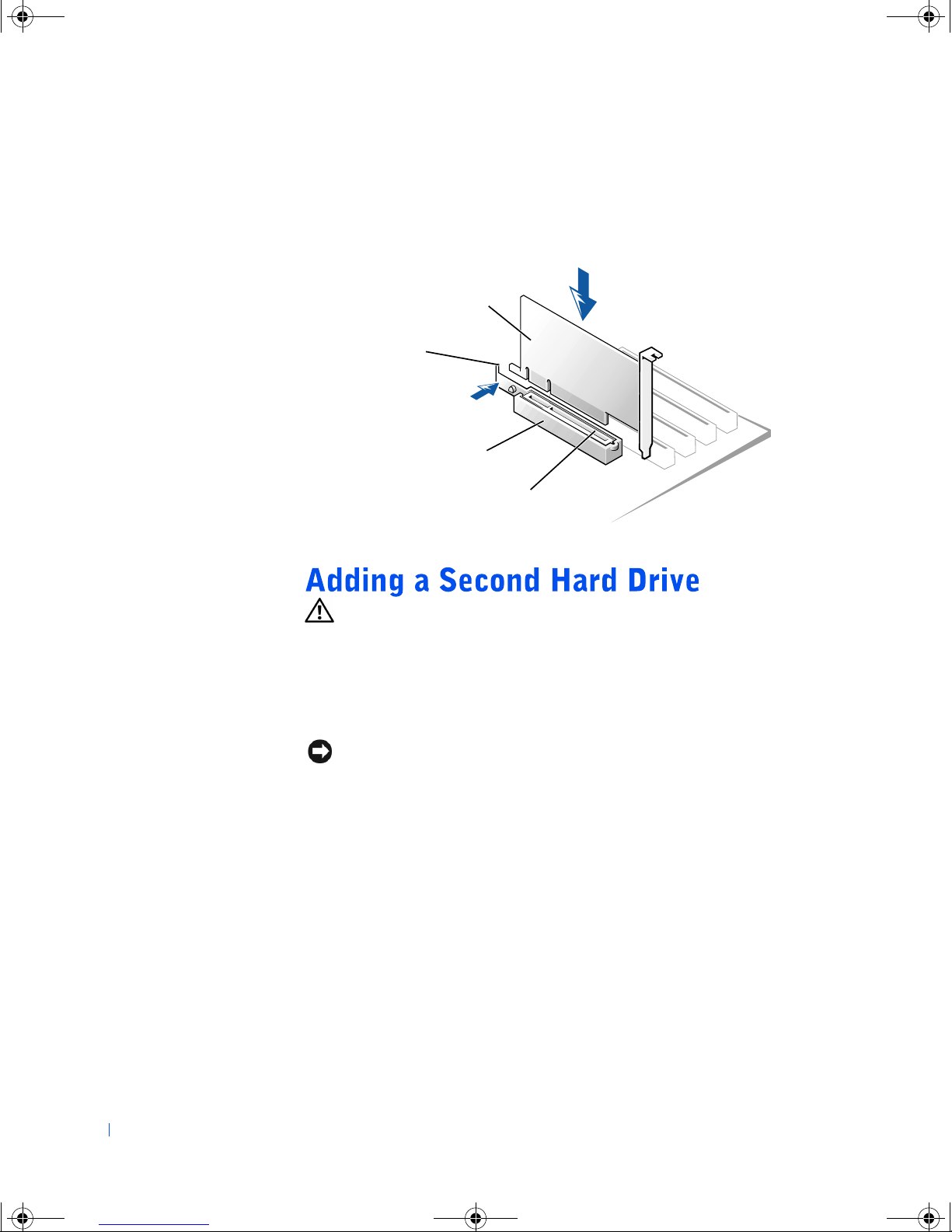
3 To replace the AGP card, gently press it down into the slot connector
until it clicks into place. Press the card clip lever while inserting the
card into the slot connector.
AGP card
card clip
lever
www.dell.com | support.dell.com
AGP card clip
slot connector
CAUTION: Before you begin any of the procedures in this section,
follow the safety instructions on page 7.
Your computer includes one hard drive. To add a second hard drive:
1 Turn off the computer and any attached devices, and disconnect them
from their electrical outlets.
NOTICE: To disconnect a network cable, first unplug the cable from your
computer and then unplug it from the network wall jack.
2
Press the power button.
3 Unpack the drive and prepare it for installation.
See the drive documentation to ensure that the drive is set up for your
computer.
4 Open the computer cover (see page 40).
5 Remove the two long, green plastic rails from the inside of the
50 Adding Parts
computer cover.
These rails are not attached to the computer cover with screws. To
remove the rails, gently ease the rails up and down.
Page 51
4C381a00.book Page 51 Thursday, June 14, 2001 9:38 AM
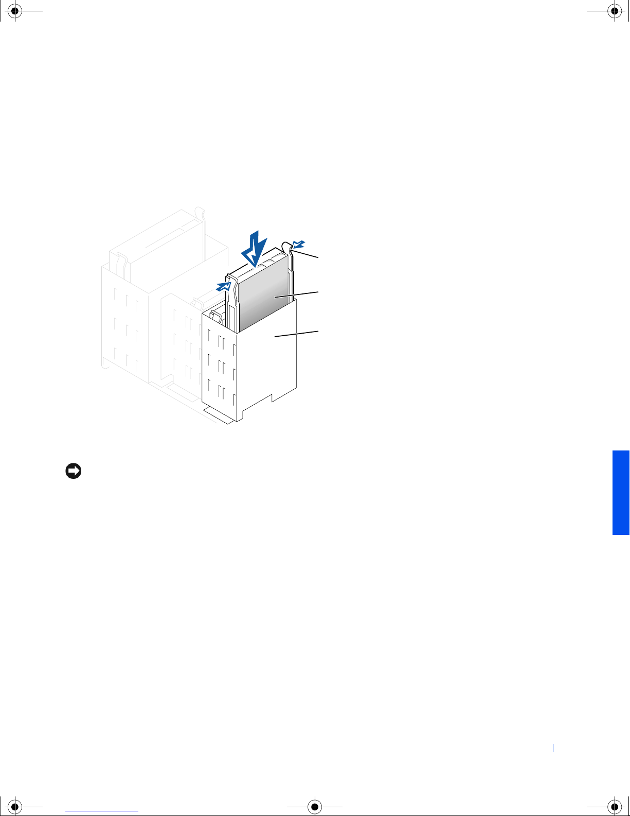
6 Attach the rails to the hard drive using the two screws supplied with
the hard drive.
Ensure that the rail tabs are positioned at the back of the hard drive.
7 Gently slide the hard drive into the bay until you hear a click.
tabs (2)
hard drive
hard drive bay
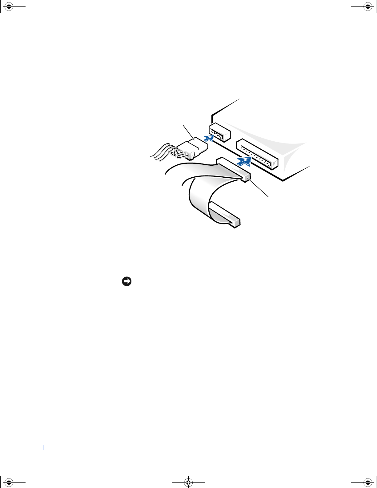
8 Connect a power cable to the drive.
NOTICE: Match the colored strip on the cable with pin 1 on the drive.
Adding Parts 51
Page 52
4C381a00.book Page 52 Thursday, June 14, 2001 9:38 AM
9 Locate the extra connector on the drive cable that is attached to your
www.dell.com | support.dell.com
first hard drive and attach the connector to the second hard drive.
power cable
drive cable
10 Close the computer cover (see page 59).
11 Connect your computer and devices to their electrical outlets, and
turn them on.
NOTICE: To connect a network cable, first plug the cable in to the network
wall jack and then plug it in to the computer.
12
See the drive documentation for instructions on installing any software
required for drive operation.
52 Adding Parts
Page 53
4C381a00.book Page 53 Thursday, June 14, 2001 9:38 AM
CAUTION: Before you begin any of the procedures in this section,
follow the safety instructions on page 7.
NOTICE: To avoid possibly damaging the drive by electrostatic discharge
(ESD), ground yourself by periodically touching an unpainted metal surface on
the back of the computer.
Your computer includes a floppy drive and a CD or DVD drive. You can add
other devices, such as a Zip drive, a CD-RW drive, or a tape drive.
5.25-Inch Devices
CAUTION: Before you begin any of the procedures in this section,
follow the safety instructions on page 7.
Turn off the computer and any attached devices, and disconnect them
1
from their electrical outlets.
NOTICE: To disconnect a network cable, first unplug the cable from your
computer and then unplug it from the network wall jack.
Press the power button.
2
3 Unpack the drive and prepare it for installation.
See the drive documentation to ensure that the drive is set up for your
computer.
4 Remove the two short, green plastic rails from the inside of the
computer cover.
HINT: Tape drives sold
by Dell come with their
own operating software
and documentation. After
you install a tape drive,
refer to the
documentation that came
with the drive for
instructions on installing
and using the tape drive
software.
These rails are not attached to the computer cover with screws. To
remove the rails, gently ease the rails up and down.
5 Attach the rails to the drive using the two screws supplied with the
drive.
Ensure that the rail tabs are positioned at the back of the drive.
6 Open the computer cover (see page 40).
Adding Parts 53
Page 54
4C381a00.book Page 54 Thursday, June 14, 2001 9:38 AM
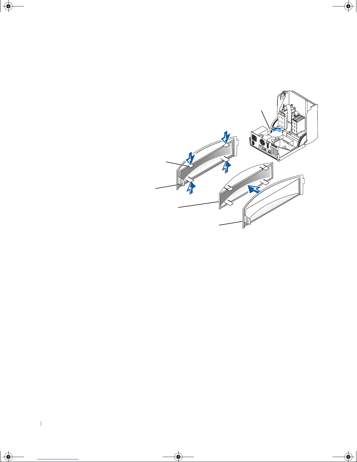
7 To remove the drive-bay cover panel, carefully press the panel out from
the inside of the computer.
remove front panel
insert through here
www.dell.com | support.dell.com
securing tabs (4)
front-panel insert
securing tab
drive-bay cover panel
front panel insert
54 Adding Parts
Page 55
4C381a00.book Page 55 Thursday, June 14, 2001 9:38 AM
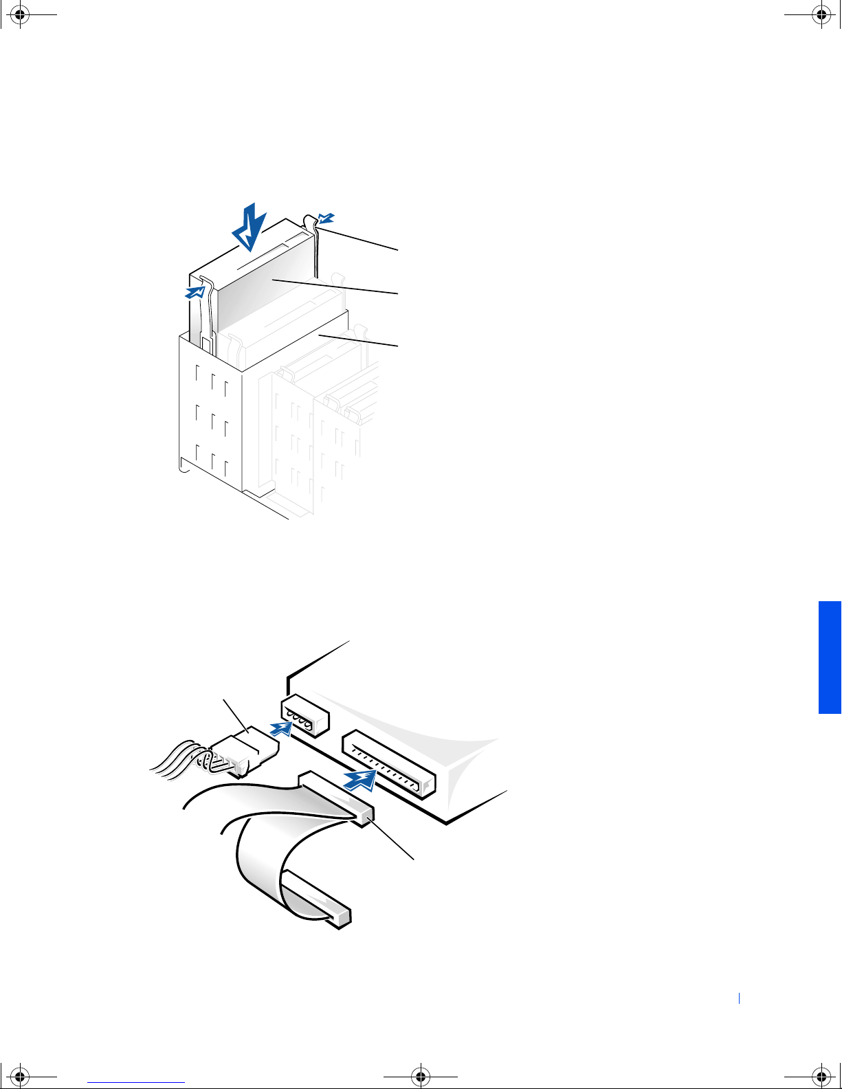
8 Gently slide the drive into the bay until you hear a click.
tabs (2)
drive
drive bay
9 Connect a power cable to the drive.
10 See the drive documentation for instructions on connecting a drive
cable to the drive and system board.
power cable
drive cable
Adding Parts 55
Page 56
4C381a00.book Page 56 Thursday, June 14, 2001 9:38 AM
11 Connect your computer and devices to their electrical outlets, and
12
3.5-Inch Devices
www.dell.com | support.dell.com
1
turn them on.
NOTICE: To connect a network cable, first plug the cable in to the network
wall jack and then plug it in to the computer.
See the drive documentation for instructions on installing any software
required for drive operation.
CAUTION: Before you begin any of the procedures in this section,
follow the safety instructions on page 7.
Turn off the computer and any attached devices, and disconnect them
from their electrical outlets.
NOTICE: To disconnect a network cable, first unplug the cable from your
computer and then unplug it from the network wall jack.
Press the power button.
2
3 Unpack the drive and prepare it for installation.
See the drive documentation to ensure that the drive is setup for your
computer.
4 Open the computer cover (see page 40).
5 To remove the drive-bay cover panel, carefully press the panel out from
the inside of the computer.
56 Adding Parts
Page 57
4C381a00.book Page 57 Thursday, June 14, 2001 9:38 AM
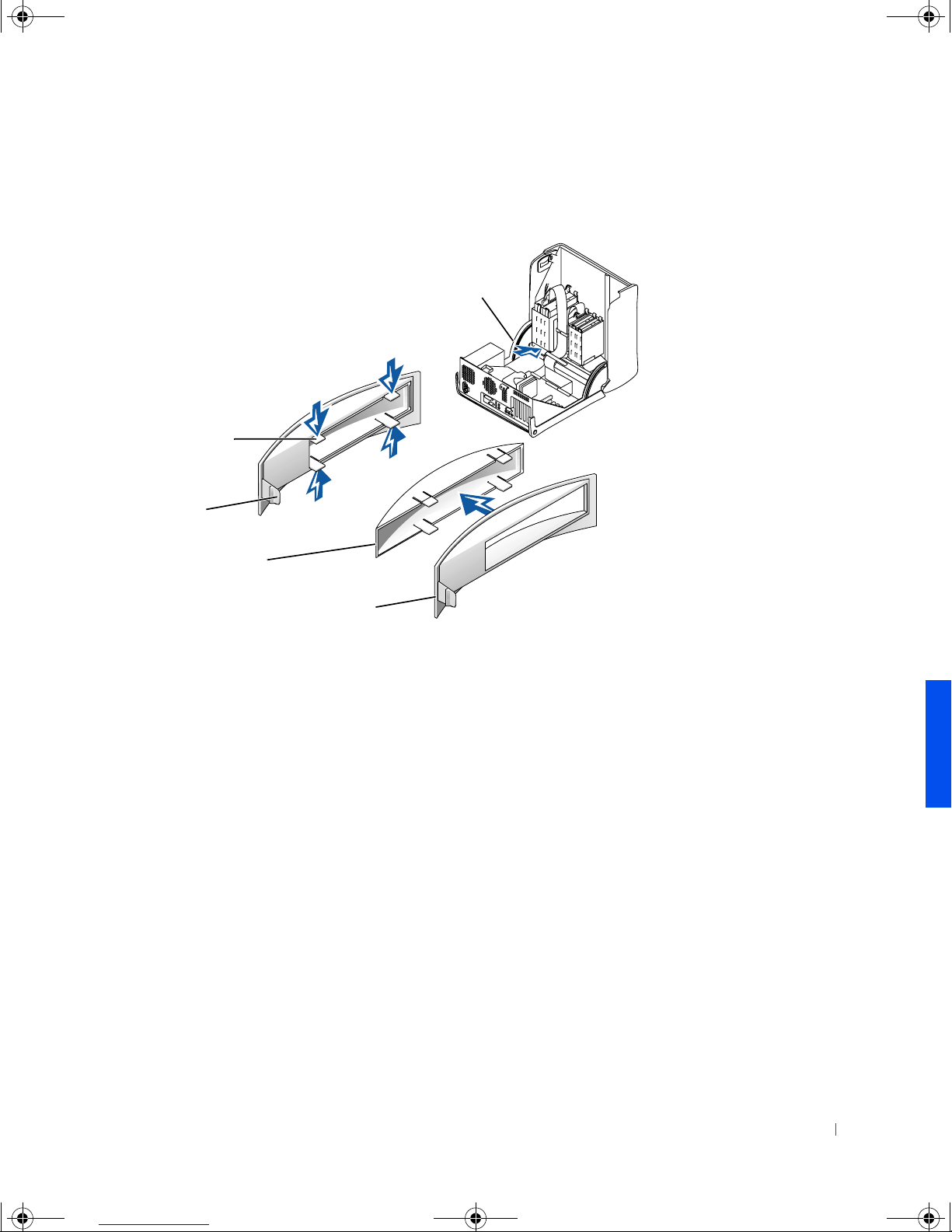
6 To remove the drive-bay cover panel insert, press the four tabs and pull
the insert away from the panel.
securing tabs (4)
remove front panel
insert through here
front panel insert
securing tab
drive-bay cover panel
front panel insert
7 Remove the two short, green plastic rails from the inside of the drive
cage.
These rails are not attached to the drive cage with screws. To remove
the rails, firmly pull the rails from the drive cage.
8 Attach the rails to the drive using the two captive screws on each rail.
Ensure that the rail tabs are positioned at the back of the drive.
Adding Parts 57
Page 58
4C381a00.book Page 58 Thursday, June 14, 2001 9:38 AM
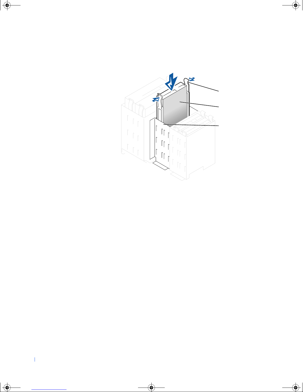
9 Gently slide the drive into the bay until you hear a click.
www.dell.com | support.dell.com
tabs (2)
drive
drive bay
10 Carefully replace the drive bay cover.
You do not need to replace the cover insert.
58 Adding Parts
Page 59
4C381a00.book Page 59 Thursday, June 14, 2001 9:38 AM
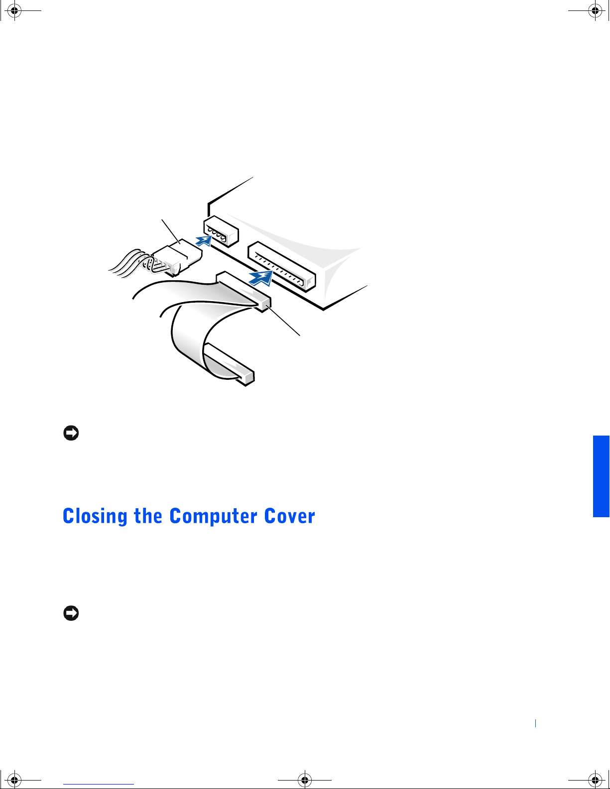
11 Connect a power cable to the drive.
12 See the drive documentation for instructions on connecting a drive
cable to the drive.
power cable
drive cable
13 Connect your computer and devices to their electrical outlets, and
turn them on.
NOTICE: To connect a network cable, first plug the cable in to the network
wall jack and then plug it in to the computer.
Install any drivers required for the drive as described in the drive
14
documentation.
1 Ensure that all cables are connected, and fold cables out of the way.
2 Ensure that no tools or extra parts are left inside the computer.
3 Pivot the cover down and ensure that the release buttons click into
place.
NOTICE: To connect a network cable, first plug the cable in to the network
wall jack and then plug it in to the computer.
Connect your computer and devices to their electrical outlets, and
4
turn them on.
Adding Parts 59
Page 60

4C381a00.book Page 60 Thursday, June 14, 2001 9:38 AM
www.dell.com | support.dell.com
60 Adding Parts
Page 61

4C381a00.book Page 61 Thursday, June 14, 2001 9:38 AM
SECTION 4
Specifications
Standard Settings
Clearing Forgotten Passwords
Replacing the Battery
Contacting Dell
Regulatory Information
Limited Warranties and Return Policy
www.dell.com | support.dell.com
Page 62
4C381a00.book Page 62 Thursday, June 14, 2001 9:38 AM
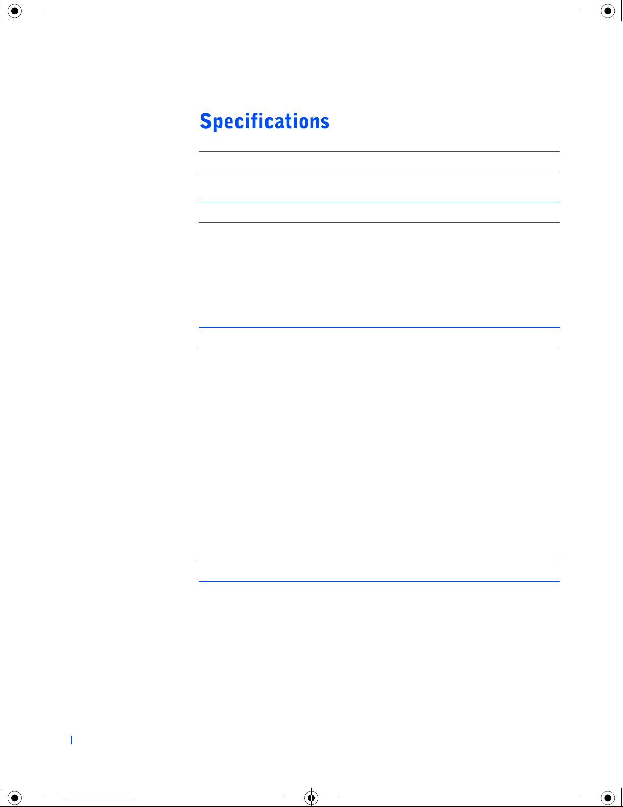
Microprocessor
Microprocessor type Intel
System Information
Chip set 815E (ICH2) with support for 66-MHz,
DMA channels eight
®
Pentium® III or Celeron™
100-MHz, and 133-MHz front-side bus
www.dell.com | support.dell.com
Interrupt levels 16
BIOS chip 4 Mb (512 KB)
Expansion Bus
Bus types 4 PCI (version 2.2), 1 AGP 4X
Bus speed PCI: 33 MHz
AGP: 66 MHz
PCI connectors four
PCI connector size 124 pins
PCI connector data width
32 bits
(maximum)
AGP connectors one
AGP connector size 128 pins
AGP connector data width
32 bits
(maximum)
Memory
Architecture non-ECC PC133 SDRAM
Memory connectors two; gold contacts
Memory capacities 64 MB, 128 MB, and 256 MB (non-ECC)
Minimum memory 64 MB (non-ECC)
Maximum memory 512 MB (non-ECC)
62 Appendix
Page 63
4C381a00.book Page 63 Thursday, June 14, 2001 9:38 AM
Memory (continued)
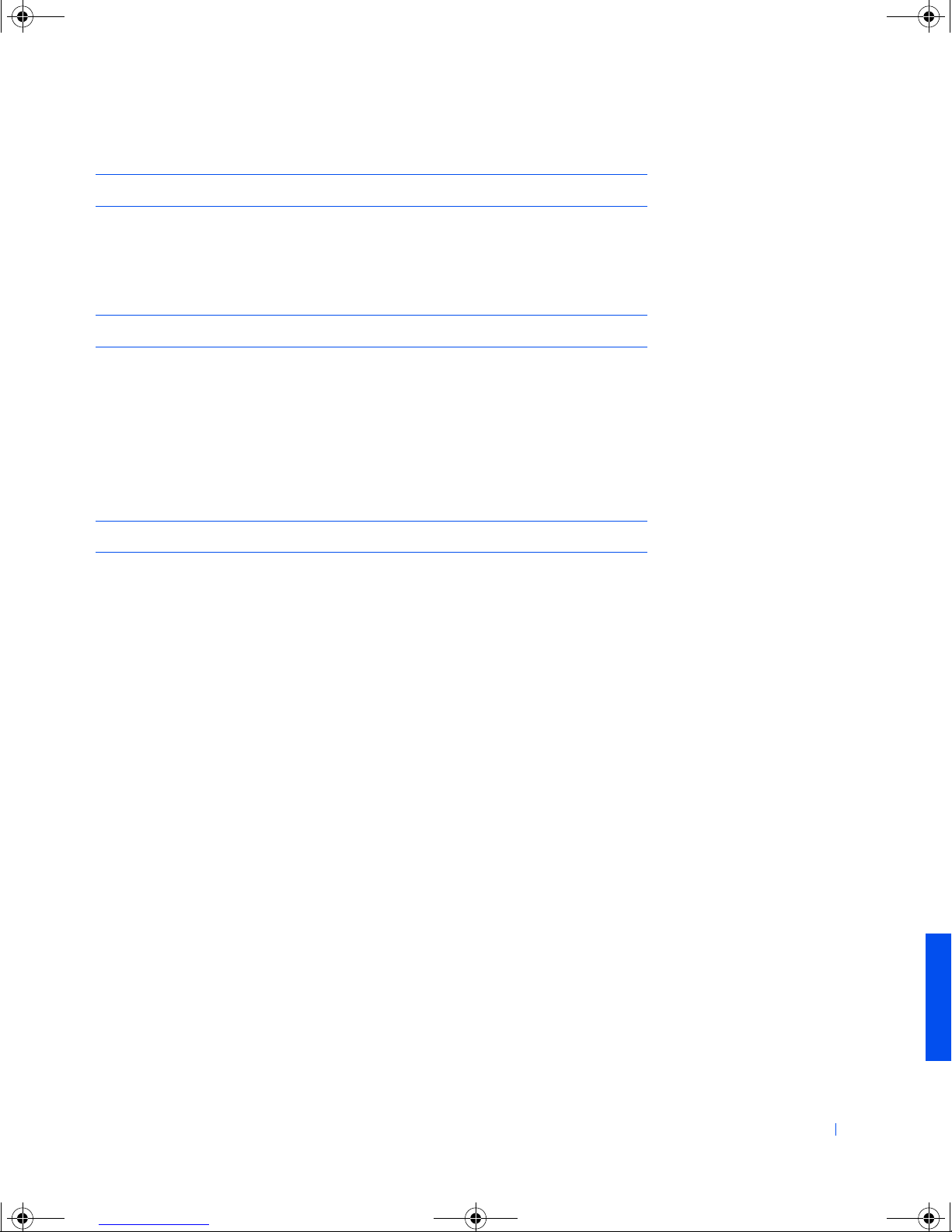
Frequency 133 MHz
Voltage 3.3 V
Data bus width 64 bits
Drives
Externally accessible two 5.25-inch bays
Internally accessible two 1-inch–high IDE hard drive bays
Available devices ATA-100 Ultra DMA hard drive, CD-RW
two 3.5-inch bays
drive, DVD drive, and DVD/CD-RW combo
drive, internal Iomega Zip drive
Ports and Connectors
Externally accessible (back panel):
Serial Data Terminal Equipment
9-pin connector; 16550C-compatible
(DTE)
Parallel 25-hole connector (bidirectional)
Video 15-hole VGA connector
Audio three miniature connectors for line in, line
out, and microphone
PS/2 6-pin mini-DIN connector or USB
connector
USB two USB-1.1–compliant connectors
Appendix 63
Page 64

4C381a00.book Page 64 Thursday, June 14, 2001 9:38 AM
Ports and Connectors (continued)
Externally accessible (front panel):
Headphone line-out connector
USB two USB-1.1–compliant connectors
Internally accessible:
Primary EIDE channel two IDE devices, 40-pin connector
Secondary EIDE channel two IDE devices, 40-pin connector
Floppy drive 34-pin connector
www.dell.com | support.dell.com
Video
Video type AGP 4X
integrated (815E) video option with 4-MB
memory upgrade option
Audio
Audio type integrated audio with SoundBlaster Pro/16
compatibility
Controls and Indicators
Power control push button
Power lights green LED on power button
blinking green in sleep state
solid green in power-on state
Dell Solutions Center control push button
Hard-drive access light green LED
Diagnostic code lights four yellow and/or green LEDs located on
back panel
64 Appendix
Page 65

4C381a00.book Page 65 Thursday, June 14, 2001 9:38 AM
Power
DC power supply:
Wattage 200 W
Heat dissipation 534 BTU (fully-loaded computer without
monitor)
Voltage
(switch-selectable on back panel)
90 to 135 V at 60 Hz; 180 to 265 V at 50 Hz;
100 V at 50 to 60 Hz for Japanese computers
Backup battery 3-V CR2032 lithium-ion coin cell
Physical
Horizontal height x width x depth 42.5 x 18.1 x 44.7 cm
(16.7 x 7.13 x 17.6 inches)
Weight 12.7 kg (28 lb)
Environmental
Temperature:
*
Operating 10° to 35°C (50° to 95°F)
Storage –40° to 65°C (–40° to 149°F)
Relative humidity 20% to 80% (noncondensing)
Maximum vibration:
Operating 0.25 G at 3 to 200 Hz at 1/2 octave/min
Storage 0.5 G at 3 to 200 Hz at 1/2 octave/min
Maximum shock:
Operating left side (for mini-tower orientation) and
Storage 27-G faired-square wave with a velocity
*
At 35°C (95°F), the maximum operating altitude is 914 m (3000 ft).
bottom half-sine pulse with a change in
velocity of 50.8 cm/sec (20 inches/sec)
change of 508 cm/sec (200 inches/sec)
Appendix 65
Page 66
4C381a00.book Page 66 Thursday, June 14, 2001 9:38 AM
Environmental (continued)
Altitude:
Operating –16 to 3048 m (–50 to 10,000 ft)
Storage –16 to 10,600 m (–50 to 35,000 ft)
*
At 35°C (95°F), the maximum operating altitude is 914 m (3000 ft).
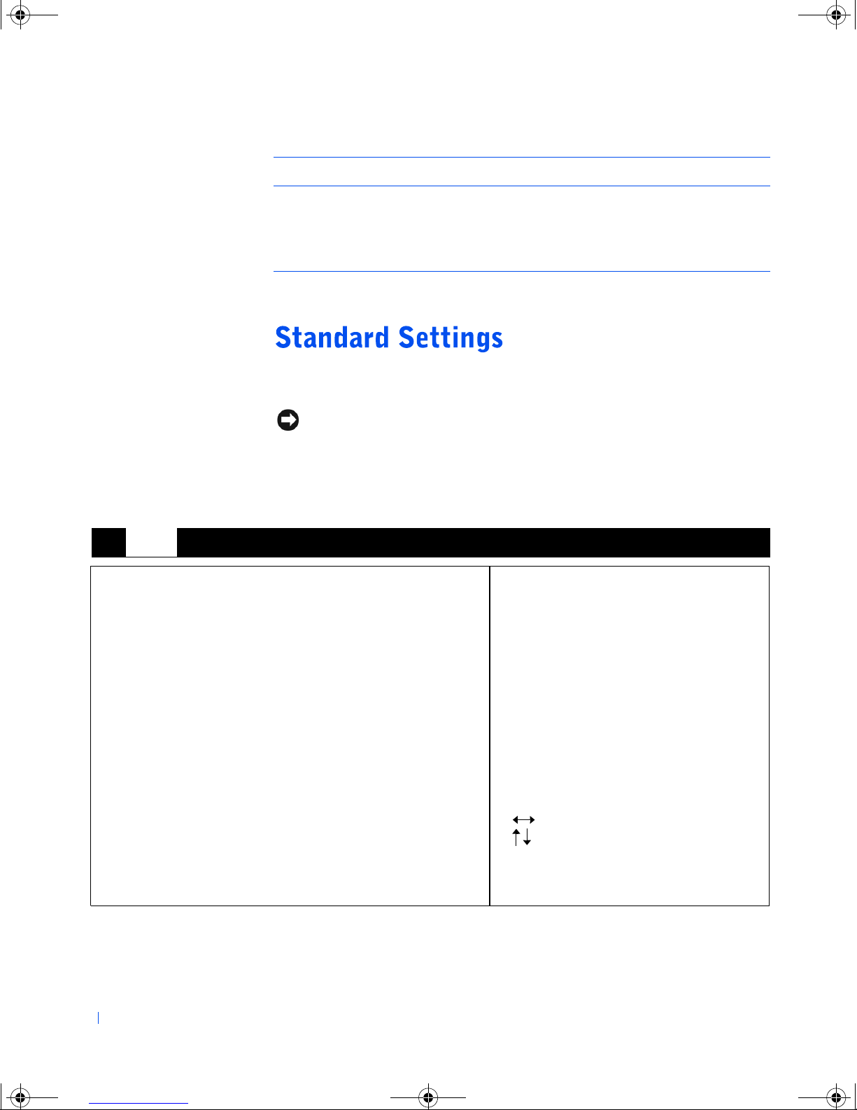
The system setup program contains the standard settings for your
www.dell.com | support.dell.com
computer.
*
NOTICE: Unless you are an expert computer user, do not change the settings
for this program. Certain changes might make your computer work incorrectly.
See the following figure for an example of the Main screen of the program.
Dell Dimension 4200 Setup
Main
BIOS Version Axx
Processor Type Intel® Celeron™
Processor Speed 800 MHz
System Bus Frequency 100 MHz
Cache RAM 128 KB
Service Tag 12ABC
Total Memory 64 MB
Memory Bank 0 64 MB [PC133]
Memory Bank 1 Not Installed
System Time: 00:00:00
System Date: MO/DY/YR
Advanced Security Power Boot Exit
+/- Cycle Time Value
Enter Select Time Field
Select Menu
Select Item
Tab Select Field
F9 Setup Defaults
F10 Save and Exit
66 Appendix
Page 67

4C381a00.book Page 67 Thursday, June 14, 2001 9:38 AM
Viewing Settings
1 Turn on (or restart) your computer.
2 When the blue Dell logo appears, press <Del> immediately.
3 If you wait too long and the operating system logo appears, continue to
wait until you see the Windows
®
desktop. Then shut down your
computer and try again.
System Setup Screens
The system setup screens are organized into the following sections:
• The menu bar at the top provides access to the main program screens:
– Main provides settings for the basic computer configuration.
– Advanced provides detailed settings for some computer features.
– Security provides indications and settings for user and setup
passwords.
– Boot provides information about how the computer starts.
– Exit provides selections for saving and loading the program
settings.
• The left side lists configuration options and their settings for the
hardware installed in your computer.
You can change settings enclosed in brackets, but not those that are a
lighter gray. Options identified by an arrowhead (>) provide access to
submenus.
• The bottom-right side lists keys and their functions for the displayed
screen.
Appendix 67
Page 68
4C381a00.book Page 68 Thursday, June 14, 2001 9:38 AM
If you forget your user or setup password, you cannot operate your computer
or change settings in the system setup program until you clear the forgotten
password(s).
1
NOTICE: The following procedure resets all standard settings for your
computer. Before proceeding, record all current settings so that you can
restore them when you finish this procedure.
Turn off the computer and unplug it from the electrical outlet (see
page 14).
www.dell.com | support.dell.com
2 Open the computer cover (see page 40).
3 Locate the recovery jumper on the system board (see page 42), and
move the jumper plug so that pins 2 and 3 are jumpered (to “clear” the
password when you turn on the computer).
4 Close the computer cover (see page 59), connect your computer to an
electrical outlet, and turn on the computer.
5 Access the system setup program and assign a new supervisor or user
password in the Maintenance menu.
6 Exit and save the system setup program settings.
7 After the computer boots, turn it off, and unplug it from the electrical
outlet.
8 Open the computer cover again.
9 Move the recovery jumper plug so that pins 1 and 2 are jumpered (the
“normal” setting).
10 Close the computer cover (see page 59), connect your computer to an
electrical outlet, and turn on the computer.
A lithium-ion coin-cell battery maintains computer configuration, date, and
time information. The battery can last several years.
If you have to repeatedly reset time and date information after turning on
the computer, replace the battery.
68 Appendix
Page 69
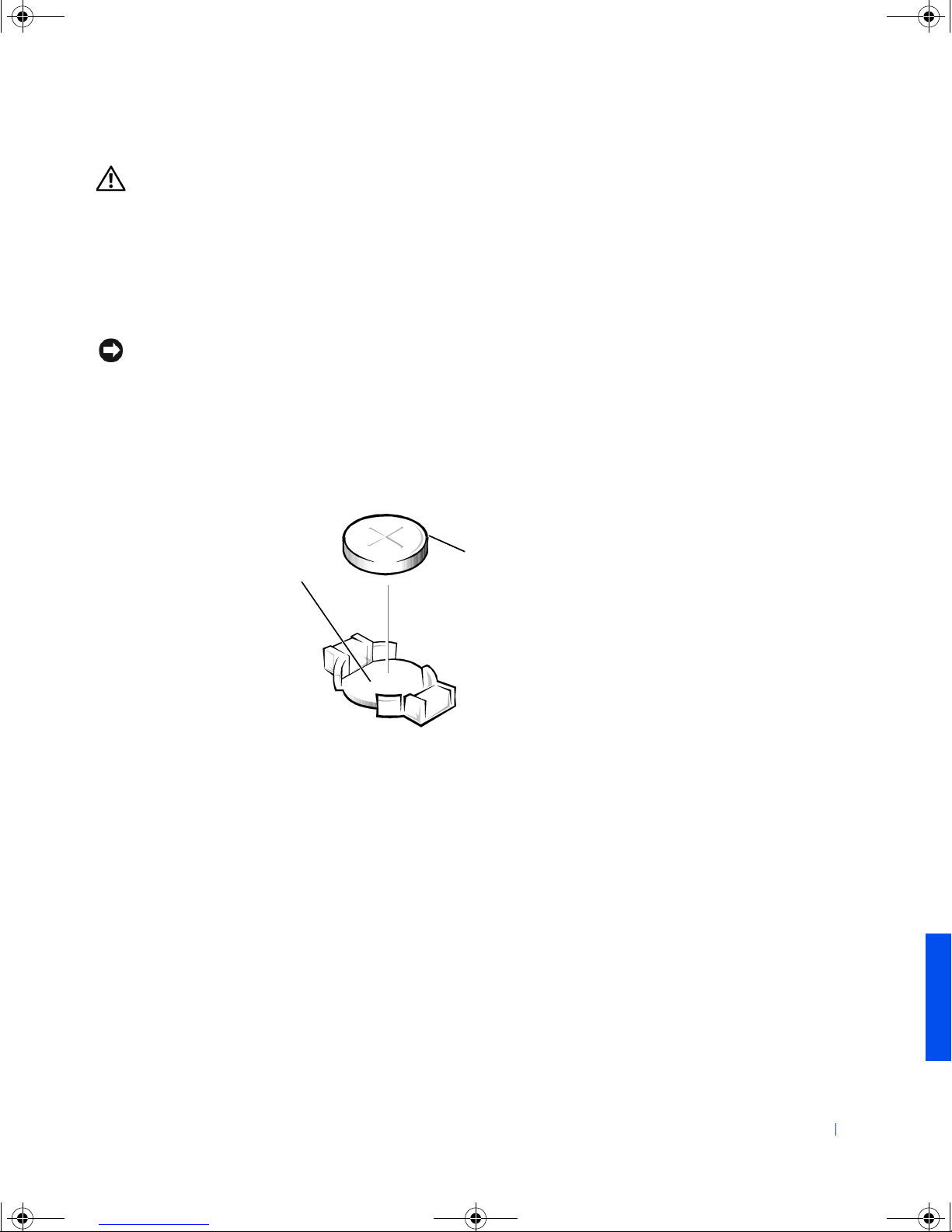
4C381a00.book Page 69 Thursday, June 14, 2001 9:38 AM
CAUTION: A new battery can explode if it is incorrectly installed.
Replace the 3-V CR2032 battery only with the same or equivalent
type recommended by the manufacturer. Discard used batteries
according to the manufacturer instructions.
Record all the screens in the system setup program so that you can
1
restore the correct settings in step 6.
2 Open the computer cover (see page 40).
NOTICE: To avoid damage to the system board while you pry the battery
loose, be sure to insert the plastic screwdriver between the battery and the
socket (not the system board).
Locate the battery socket (see page 42) and pry the battery out of its
3
socket with your fingers or with a plastic screwdriver.
4 Insert the battery into the socket with the side labeled “+” facing up.
battery
battery socket
5 Close the computer cover (see page 59), and connect your computer
and devices to their electrical outlets.
6 Access the system setup program and restore the settings you recorded
in step 1.
For battery disposal guidelines, see page 88.
Appendix 69
Page 70
4C381a00.book Page 70 Thursday, June 14, 2001 9:38 AM
HINT: Toll-free numbers
are for use within the
country for which they are
listed.
Country (City)
International Access Code
www.dell.com | support.dell.com
Country Code
City Code
Australia (Sydney)
International Access Code: 0011
Country Code: 61
City Code: 2
Austria (Vienna)
International Access Code: 900
Country Code: 43
City Code: 1
When you need to contact Dell, use the telephone numbers, codes, and
electronic addresses provided in the following tables. If you need assistance
in determining which codes to use, contact a local or an international
operator.
Contact Numbers and Addresses
Department Name or Service Area,
Website and E-mail Address
Home and Small Business 1-300-65-55-33
Government and Business toll free: 1-800-633-559
Preferred Accounts Division (PAD) toll free: 1-800-060-889
Customer Care toll free: 1-800-819-339
Corporate Sales toll free: 1-800-808-385
Transaction Sales toll free: 1-800-808-312
Fax toll free: 1-800-818-341
Home/Small Business Sales 01 795 67602
Home/Small Business Fax 01 795 67605
Home/Small Business Customer Care 01 795 67603
Preferred Accounts/Corporate Customer Care 0660 8056
Home/Small Business Technical Support 01 795 67604
Preferred Accounts/Corporate Technical Support 0660 8779
Switchboard 01 491 04 0
Website: http://support.euro.dell.com
E-mail: [email protected]
Local Numbers, and
Toll Free Numbers
Area Codes,
70 Appendix
Page 71
4C381a00.book Page 71 Thursday, June 14, 2001 9:38 AM
Country (City)
International Access Code
Country Code
City Code
Belgium (Brussels)
International Access Code: 00
Country Code: 32
City Code: 2
Brazil
International Access Code: 0021
Country Code: 55
City Code: 51
Brunei
Country Code: 673
Canada (North York, Ontario)
International Access Code: 011
Chile (Santiago)
Country Code: 56
City Code: 2
Department Name or Service Area,
Website and E-mail Address
Local Numbers, and
Area Codes,
Toll Free Numbers
Technical Support 02 481 92 88
Customer Care 02 481 91 19
Home/Small Business Sales toll free: 0800 16884
Corporate Sales 02 481 91 00
Fax 02 481 92 99
Switchboard 02 481 91 00
Website: http://support.euro.dell.com
E-mail: [email protected]
Customer Support, Technical Support 0800 90 3355
Tech Support Fax 55 51 481 5470
Sales 0800 90 3366
Website: http://www.dell.com/br
Customer Technical Support (Penang, Malaysia) 604 633 4966
Customer Service (Penang, Malaysia) 604 633 4949
Transaction Sales (Penang, Malaysia) 604 633 4955
Automated Order-Status System toll free: 1-800-433-9014
AutoTech (Automated technical support) toll free: 1-800-247-9362
Customer Care (From outside Toronto) toll free: 1-800-387-5759
Customer Care (From within Toronto) 416 758-2400
Customer Technical Support toll free: 1-800-847-4096
Sales (Direct Sales—from outside Toronto) toll free: 1-800-387-5752
Sales (Direct Sales—from within Toronto) 416 758-2200
Sales (Federal government, education, and
toll free: 1-800-567-7542
medical)
Sales (Major Accounts) toll free: 1-800-387-5755
TechFax toll free: 1-800-950-1329
Sales, Customer Support, and Technical Support toll free: 1230-020-4823
Appendix 71
Page 72
4C381a00.book Page 72 Thursday, June 14, 2001 9:38 AM
Country (City)
International Access Code
Country Code
City Code
China (Xiamen)
Country Code: 86
City Code: 592
www.dell.com | support.dell.com
Czech Republic (Prague)
International Access Code: 00
Country Code: 420
City Code: 2
Denmark (Horsholm)
International Access Code: 00
Country Code: 45
Department Name or Service Area,
Website and E-mail Address
Local Numbers, and
Area Codes,
Toll Free Numbers
Home and Small Business Technical Support toll free: 800 858 2437
Corporate Accounts Technical Support toll free: 800 858 2333
Customer Experience toll free: 800 858 2060
Home and Small Business toll free: 800 858 2222
Preferred Accounts Division toll free: 800 858 2062
Large Corporate Accounts North toll free: 800 858 2999
Large Corporate Accounts East toll free: 800 858 2020
Large Corporate Accounts South toll free: 800 858 2355
Large Corporate Accounts GCP toll free: 800 858 2055
Large Corporate Accounts HK toll free: 800 964108
Large Corporate Accounts GCP HK toll free: 800 907308
Technical Support 02 22 83 27 27
Customer Care 02 22 83 27 11
Fax 02 22 83 27 14
TechFax 02 22 83 27 28
Switchboard 02 22 83 27 11
Website: http://support.euro.dell.com
E-mail: [email protected]
Technical Support 45170182
Relational Customer Care 45170184
Home/Small Business Customer Care 32875505
Switchboard 45170100
Fax Technical Support (Upplands Vasby, Sweden) 46 0 859005594
Fax Switchboard 45170117
Website: http://support.euro.dell.com
E-mail: [email protected]
E-mail Support for Servers:
[email protected]
72 Appendix
Page 73
4C381a00.book Page 73 Thursday, June 14, 2001 9:38 AM
Country (City)
International Access Code
Country Code
City Code
Finland (Helsinki)
International Access Code: 990
Country Code: 358
City Code: 9
France (Paris/Montpellier)
International Access Code: 00
Country Code: 33
City Code: (1) (4)
Department Name or Service Area,
Website and E-mail Address
Local Numbers, and
Area Codes,
Toll Free Numbers
Technical Support 09 253 313 60
Technical Support Fax 09 253 313 81
Relational Customer Care 09 253 313 38
Home/Small Business Customer Care 09 693 791 94
Fax 0925331399
Switchboard 09 253 313 00
Website: http://support.euro.dell.com
E-mail: [email protected]
Home and Small Business
Technical Support 0825 387 270
Customer Care 0825 823 833
Switchboard 0825 004 700
Switchboard (Alternative) 04 99 75 40 00
Sales 0825 004 700
Fax 0825 004 701
Website: http://support.euro.dell.com
E-mail: [email protected]
Corporate
Technical Support 0825 004 719
Customer Care 0825 338 339
Switchboard 01 55 94 71 00
Sales 01 55 94 71 00
Fax 0155947101
Website: http://support.euro.dell.com
E-mail: [email protected]
Appendix 73
Page 74
4C381a00.book Page 74 Thursday, June 14, 2001 9:38 AM
Country (City)
International Access Code
Country Code
City Code
Germany (Langen)
International Access Code: 00
Country Code: 49
City Code: 6103
www.dell.com | support.dell.com
Hong Kong
International Access Code: 001
Country Code: 852
Ireland (Cherrywood)
International Access Code: 16
Country Code: 353
City Code: 1
Department Name or Service Area,
Website and E-mail Address
Local Numbers, and
Area Codes,
Toll Free Numbers
Technical Support 06103 766-7200
Home/Small Business Customer Care 0180-5-224400
Global Segment Customer Care 06103 766-9570
Preferred Accounts Customer Care 06103 766-9420
Large Accounts Customer Care 06103 766-9560
Public Accounts Customer Care 06103 766-9555
Switchboard 06103 766-7000
Website: http://support.euro.dell.com
E-mail: [email protected]
Technical Support toll free: 800 96 4107
Customer Service (Penang, Malaysia) 604 633 4949
Transaction Sales toll free: 800 96 4109
Corporate Sales toll free: 800 96 4108
Technical Support 0870 908 0800
Home User Customer Care 01 204 4095
Small Business Customer Care 01 204 4026
Corporate Customer Care 01 204 4003
Sales 01 286 0500
SalesFax 01 204 0144
Fax 0870 907 5590
Switchboard 01 286 0500
Website: http://support.euro.dell.com
E-mail: [email protected]
74 Appendix
Page 75

4C381a00.book Page 75 Thursday, June 14, 2001 9:38 AM
Country (City)
International Access Code
Country Code
City Code
Italy (Milan)
International Access Code: 00
Country Code: 39
City Code: 02
Department Name or Service Area,
Website and E-mail Address
Local Numbers, and
Area Codes,
Toll Free Numbers
Home and Small Business
Technical Support 02 577 826 90
Customer Care 02 696 821 14
Fax 0269682113
Switchboard 02 696 821 12
Website: http://support.euro.dell.com
E-mail: [email protected]
Corporate
Technical Support 02 577 826 90
Customer Care 02 577 825 55
Fax 0257503530
Switchboard 02 577 821
Website: http://support.euro.dell.com
E-mail: [email protected]
Appendix 75
Page 76

4C381a00.book Page 76 Thursday, June 14, 2001 9:38 AM
Country (City)
International Access Code
Country Code
City Code
Japan (Kawasaki)
International Access Code: 001
Country Code: 81
City Code: 44
www.dell.com | support.dell.com
Korea (Seoul)
International Access Code: 001
Country Code: 82
City Code: 2
Department Name or Service Area,
Website and E-mail Address
Local Numbers, and
Area Codes,
Toll Free Numbers
Technical Support (Server)
Technical Support Outside of Japan (Server)
Technical Support (Dimension™ and Inspiron™)
toll free: 0120-1984-35
81-44-556-4152
toll free: 0120-1982-26
Technical Support Outside of Japan (Dimension
and Inspiron)
Technical Support (Dell Precision™, OptiPlex™
81-44-520-1435
toll free: 0120-1984-33
and Latitude™)
Technical Support Outside of Japan (Dell
81-44-556-3894
Precision, OptiPlex, and Latitude)
24-Hour Automated Order Service 044 556-3801
Customer Care 044 556-4240
Business Sales Division (up to 400 employees) 044 556 3494
Preferred Accounts Division Sales (over 400
044 556-3433
employees)
Large Corporate Accounts Sales (over 3500
044 556-3440
employees)
Public Sales (Government Agencies, Educational
044 556 3440
Institutions, and Medical Institutions)
Global Segment Japan 044 556 3469
Individual User 044 556 1657
Faxbox Service 044 556-3490
Switchboard 044 556-4300
Website: http://support.jp.dell.com
Technical Support toll free: 080-200-3800
Sales toll free: 080-200-3600
Customer Service (Seoul, Korea) toll free: 080-200-3800
Customer Service (Penang, Malaysia) 604 633 4949
Fax 2194-6202
Switchboard 2194-6000
76 Appendix
Page 77
4C381a00.book Page 77 Thursday, June 14, 2001 9:38 AM
Country (City)
International Access Code
Department Name or Service Area,
Website and E-mail Address
Country Code
City Code
Latin America Customer Technical Support (Austin, Texas,
U.S.A.)
Customer Service (Austin, Texas, U.S.A.) 512 728-3619
Fax (Technical Support and Customer
Service)(Austin, Texas, U.S.A.)
Sales (Austin, Texas, U.S.A.) 512 728-4397
SalesFax (Austin, Texas, U.S.A.) 512 728-4600
Luxembourg
International Access Code: 00
Country Code: 352
Technical Support (Brussels, Belgium) 02 481 92 88
Home/Small Business Sales (Brussels, Belgium) toll free: 080016884
Corporate Sales (Brussels, Belgium) 02 481 91 00
Customer Care (Brussels, Belgium) 02 481 91 19
Fax (Brussels, Belgium) 02 481 92 99
Switchboard (Brussels, Belgium) 02 481 91 00
Website: http://support.euro.dell.com
E-mail: [email protected]
Macau
Country Code: 853
Technical Support toll free: 0800 582
Customer Service (Penang, Malaysia) 604 633 4949
Transaction Sales toll free: 0800 581
Malaysia (Penang)
International Access Code: 00
Country Code: 60
City Code: 4
Technical Support toll free: 1 800 888 298
Customer Service 04 633 4949
Transaction Sales toll free: 1 800 888 202
Corporate Sales toll free: 1 800 888 213
Area Codes,
Local Numbers, and
Toll Free Numbers
512 728-4093
512 728-3883
or 512 728-3772
Appendix 77
Page 78
4C381a00.book Page 78 Thursday, June 14, 2001 9:38 AM
Country (City)
International Access Code
Country Code
City Code
Mexico
International Access Code: 00
Country Code: 52
www.dell.com | support.dell.com
Netherlands (Amsterdam)
International Access Code: 00
Country Code: 31
City Code: 20
New Zealand
International Access Code: 00
Country Code: 64
Department Name or Service Area,
Website and E-mail Address
Local Numbers, and
Area Codes,
Toll Free Numbers
Customer Technical Support 001-877-384-8979
or 001-877-269-3383
Sales 50-81-8800
or 01-800-888-3355
Customer Service 001-877-384-8979
or 001-877-269-3383
Main 50-81-8800
or 01-800-888-3355
Technical Support 020 581 8838
Customer Care 020 581 8740
Home/Small Business Sales toll free: 0800-0663
Home/Small Business Sales Fax 020 682 7171
Corporate Sales 020 581 8818
Corporate Sales Fax 020 686 8003
Fax 020 686 8003
Switchboard 020 581 8818
Website: http://support.euro.dell.com
E-mail: [email protected]
Home and Small Business 0800 446 255
Government and Business 0800 444 617
Sales 0800 441 567
Fax 0800 441 566
78 Appendix
Page 79
4C381a00.book Page 79 Thursday, June 14, 2001 9:38 AM
Country (City)
International Access Code
Country Code
City Code
Norway (Lysaker)
International Access Code: 00
Country Code: 47
Poland (Warsaw)
International Access Code: 011
Country Code: 48
City Code: 22
Portugal
International Access Code: 00
Country Code: 35
Singapore (Singapore)
International Access Code: 005
Country Code: 65
Department Name or Service Area,
Website and E-mail Address
Local Numbers, and
Area Codes,
Toll Free Numbers
Technical Support 671 16882
Relational Customer Care 671 17514
Home/Small Business Customer Care 23162298
Switchboard 671 16800
Fax Technical Support (Upplands Vasby, Sweden) 46 0 85 590 05 594
Fax Switchboard 671 16865
Website: http://support.euro.dell.com
E-mail: [email protected]
E-mail Support for Servers:
[email protected]
Technical Support 22 57 95 700
Customer Care 22 57 95 999
Sales 22 57 95 999
Fax 22 57 95 998
Switchboard 22 57 95 999
Website: http://support.euro.dell.com
E-mail: [email protected]
Technical Support 35 800 834 077
Customer Care 800 300 415 or
35 800 834 075
Sales 800 300 410 or
800 300 411 or
800 300 412 or
351 214 220 710
Fax 35 121 424 01 12
E-mail: [email protected]
Technical Support toll free: 800 6011 051
Customer Service (Penang, Malaysia) 604 633 4949
Transaction Sales toll free: 800 6011 054
Corporate Sales toll free: 800 6011 053
Appendix 79
Page 80
4C381a00.book Page 80 Thursday, June 14, 2001 9:38 AM
Country (City)
International Access Code
Country Code
City Code
South Africa (Johannesburg)
International Access Code:
09/091
Country Code: 27
City Code: 11
www.dell.com | support.dell.com
Southeast Asian and Pacific
Countries
Spain (Madrid)
International Access Code: 00
Country Code: 34
City Code: 91
Department Name or Service Area,
Website and E-mail Address
Local Numbers, and
Area Codes,
Toll Free Numbers
Technical Support 011 709 7710
Customer Care 011 709 7707
Sales 011 709 7700
Fax 011 706 0495
Switchboard 011 709 7700
Website: http://support.euro.dell.com
E-mail: [email protected]
Customer Technical Support, Customer Service,
604 633 4810
and Sales (Penang, Malaysia)
Home and Small Business
Technical Support 902 100 130
Customer Care 902 118 540
Sales 902 118 541
Switchboard 902 118 541
Fax 902 118 539
Website: http://support.euro.dell.com
E-mail: [email protected]
Corporate
Technical Support 902 100 130
Customer Care 902 118 546
Switchboard 91 722 92 00
Fax 91 722 95 83
Website: http://support.euro.dell.com
E-mail: [email protected]
80 Appendix
Page 81
4C381a00.book Page 81 Thursday, June 14, 2001 9:38 AM
Country (City)
International Access Code
Country Code
City Code
Sweden (Upplands Vasby)
International Access Code: 00
Country Code: 46
City Code: 8
Switzerland (Geneva)
International Access Code: 00
Country Code: 41
City Code: 22
Ta i wa n
International Access Code: 002
Country Code: 886
Thailand
International Access Code: 001
Country Code: 66
Department Name or Service Area,
Website and E-mail Address
Local Numbers, and
Area Codes,
Toll Free Numbers
Technical Support 08 590 05 199
Relational Customer Care 08 590 05 642
Home/Small Business Customer Care 08 587 70 527
Fax Technical Support 08 590 05 594
Sales 08 590 05 185
Website: http://support.euro.dell.com
E-mail: [email protected]
E-mail Support for Latitude and Inspiron:
[email protected]
E-mail Support for OptiPlex: [email protected]
E-mail Support for Servers:
[email protected]
Technical Support (Home and Small Business) 0844 811 411
Technical Support (Corporate) 0844 822 844
Customer Care (Home and Small Business) 0848 802 202
Customer Care (Corporate) 0848 821 721
Fax 0227990190
Switchboard 022 799 01 01
Website: http://support.euro.dell.com
E-mail: [email protected]
Technical Support toll free: 0080 60 1255
Technical Support (Servers) toll free: 0080 60 1256
Transaction Sales toll free: 0080 651 228
or 0800 33 556
Corporate Sales toll free: 0080 651 227
or 0800 33 555
Technical Support toll free: 0880 060 07
Customer Service (Penang, Malaysia) 604 633 4949
Sales toll free: 0880 060 09
Appendix 81
Page 82

4C381a00.book Page 82 Thursday, June 14, 2001 9:38 AM
Country (City)
International Access Code
Country Code
City Code
U.K. (Bracknell)
International Access Code: 010
Country Code: 44
City Code: 1344
www.dell.com | support.dell.com
Department Name or Service Area,
Website and E-mail Address
Local Numbers, and
Area Codes,
Toll Free Numbers
Technical Support (Corporate/Preferred
0870 908 0500
Accounts/PAD [1000+ employees])
Technical Support (Direct/PAD and General) 0870 908 0800
Global Accounts Customer Care 01344 723186
Home and Small Business Customer Care 0870 906 0010
Corporate Customer Care 0870 908 0500
Preferred Accounts (500-5000 employees)
01344 723196
Customer Care
Central Government Customer Care 01344 723193
Local Government Customer Care 01344 723194
Home/Small Business Sales 0870 907 4000
Corporate/Public Sector Sales 01344 860456
Website: http://support.euro.dell.com
E-mail: [email protected]
82 Appendix
Page 83

4C381a00.book Page 83 Thursday, June 14, 2001 9:38 AM
Country (City)
International Access Code
Country Code
City Code
U.S.A. (Austin, Texas)
International Access Code: 011
Country Code: 1
Department Name or Service Area,
Website and E-mail Address
Local Numbers, and
Area Codes,
Toll Free Numbers
Automated Order-Status System toll free: 1-800-433-9014
AutoTech (for portable and desktop computers) toll free: 1-800-247-9362
Dell Home and Small Business Group (for portable and desktop computers):
Customer Technical Support (Return Material
toll free: 1-800-624-9896
Authorization Numbers)
Customer Technical Support (Home sales
toll free: 1-877-576-3355
purchased via http://www.dell.com)
Customer Service (Credit Return Authorization
toll free: 1-800-624-9897
Numbers)
National Accounts (systems purchased by established Dell national accounts
[have your account number handy], medical institutions, or value-added resellers
[VARs]):
Customer Service and Technical Support (Return
toll free: 1-800-822-8965
Material Authorization Numbers)
Public Americas International (systems purchased by governmental agencies
[local, state, or federal] or educational institutions):
Customer Service and Technical Support (Return
toll free: 1-800-234-1490
Material Authorization Numbers)
Dell Sales toll free: 1-800-289-3355
or toll free: 1-800-879-3355
Spare Parts Sales toll free: 1-800-357-3355
DellWare™ toll free: 1-800-753-7201
Desktop and Portable Fee-Based Technical Support toll free: 1-800-433-9005
Server Fee-Based Technical Support toll free: 1-800-967-0765
Sales (Catalogs) toll free: 1-800-426-5150
Fax toll free: 1-800-727-8320
TechFax toll free: 1-800-950-1329
Dell Services for the Deaf, Hard-of-Hearing, or
Speech-Impaired
toll free: 1-877-DELLTTY
(1-877-335-5889)
Switchboard 512 338-4400
Dellnet Technical Support toll free: 1-877-Dellnet
(1-877-335-5638)
Appendix 83
Page 84
4C381a00.book Page 84 Thursday, June 14, 2001 9:38 AM
Returning Items for Warranty Repair or Credit
Prepare all items being returned, whether for repair or credit, as follows:
1 Call Dell to obtain an authorization number, and write it clearly and
2 Include a copy of the invoice and a letter describing the reason for the
3 Include any accessories that belong with the item(s) being returned
4 Pack the equipment to be returned in the original (or equivalent)
www.dell.com | support.dell.com
You are responsible for paying shipping expenses. You are also responsible
for insuring any product returned, and you assume the risk of loss during
shipment to Dell. Collect-on-delivery packages are not accepted.
prominently on the outside of the box.
return.
(power cables, CDs, guides, and so on) if the return is for credit.
packing materials.
Returns that are missing any of the preceding requirements will be refused
at our receiving dock and returned to you.
Electromagnetic Interference (EMI) is any signal or emission, radiated in
free space or conducted along power or signal leads, that endangers the
functioning of a radio navigation or other safety service or seriously
degrades, obstructs, or repeatedly interrupts a licensed radio
communications service. Radio communications services include but are
not limited to AM/FM commercial broadcast, television, cellular services,
radar, air-traffic control, pager, and Personal Communication Services
(PCS). These licensed services, along with unintentional radiators such as
digital devices, including computer systems, contribute to the
electromagnetic environment.
84 Appendix
Page 85

4C381a00.book Page 85 Thursday, June 14, 2001 9:38 AM
Electromagnetic Compatibility (EMC) is the ability of items of electronic
equipment to function properly together in the electronic environment.
While this computer system has been designed and determined to be
compliant with regulatory agency limits for EMI, there is no guarantee that
interference will not occur in a particular installation. If this equipment
does cause interference with radio communications services, which can be
determined by turning the equipment off and on, you are encouraged to try
to correct the interference by one or more of the following measures:
• Reorient the receiving antenna.
• Relocate the computer with respect to the receiver.
• Move the computer away from the receiver.
• Plug the computer into a different outlet so that the computer and the
receiver are on different branch circuits.
If necessary, consult a Dell Technical Support representative or an
experienced radio/television technician for additional suggestions. You may
find the FCC Interference Handbook, 1986, to be helpful. It is available from
the U.S. Government Printing Office, Washington, DC 20402, Stock
No. 004-000-00450-7 or on the World Wide Web at
http://www.fcc.gov/cib/Publications/tvibook.html.
Dell computer systems are designed, tested, and classified for their
intended electromagnetic environment. These electromagnetic
environment classifications generally refer to the following harmonized
definitions:
• Class A is typically for business or industrial environments.
• Class B is typically for residential environments.
Information Technology Equipment (ITE), including peripherals,
expansion cards, printers, input/output (I/O) devices, monitors, and so on,
that are integrated into or connected to the system should match the
electromagnetic environment classification of the computer system.
Appendix 85
Page 86

4C381a00.book Page 86 Thursday, June 14, 2001 9:38 AM
A Notice About Shielded Signal Cables: Use only shielded cables for
connecting peripherals to any Dell device to reduce the possibility of
interference with radio communications services. Using shielded cables
ensures that you maintain the appropriate EMC classification for the
intended environment. For parallel printers, a cable is available from Dell.
If you prefer, you can order a cable from Dell on the World Wide Web at
http://accessories.us.dell.com/.
Most Dell computer systems are classified for Class B environments. To
determine the electromagnetic classification for your system or device, refer
to the following sections specific for each regulatory agency. Each section
provides country-specific EMC/EMI or product safety information.
www.dell.com | support.dell.com
FCC Notices (U.S. Only)
Most Dell computer systems are classified by the Federal Communications
Commission (FCC) as Class B digital devices. However, the inclusion of
certain options can change the rating of some configurations to Class A. To
determine which classification applies to your computer system, examine all
FCC registration labels located on the bottom or back panel of your
computer, on card-mounting brackets, and on the cards themselves. If any
one of the labels carries a Class A rating, your entire system is considered to
be a Class A digital device. If all labels carry an FCC Class B rating as
distinguished by either an FCC ID number or the FCC logo, ( ), your
system is considered to be a Class B digital device.
Once you have determined your system’s FCC classification, read the
appropriate FCC notice. Note that FCC regulations provide that changes
or modifications not expressly approved by Dell could void your authority to
operate this equipment.
This device complies with Part 15 of the FCC Rules. Operation is subject to
the following two conditions:
• This device may not cause harmful interference.
• This device must accept any interference received, including
interference that may cause undesired operation.
86 Appendix
Page 87

4C381a00.book Page 87 Thursday, June 14, 2001 9:38 AM
Class A
This equipment has been tested and found to comply with the limits for a
Class A digital device pursuant to Part 15 of the FCC Rules. These limits
are designed to provide reasonable protection against harmful interference
when the equipment is operated in a commercial environment. This
equipment generates, uses, and can radiate radio frequency energy and, if
not installed and used in accordance with the manufacturer’s instruction
manual, may cause harmful interference with radio communications.
Operation of this equipment in a residential area is likely to cause harmful
interference, in which case you will be required to correct the interference at
your own expense.
Class B
This equipment has been tested and found to comply with the limits for a
Class B digital device pursuant to Part 15 of the FCC Rules. These limits are
designed to provide reasonable protection against harmful interference in a
residential installation. This equipment generates, uses, and can radiate
radio frequency energy and, if not installed and used in accordance with the
manufacturer’s instruction manual, may cause interference with radio
communications. However, there is no guarantee that interference will not
occur in a particular installation. If this equipment does cause harmful
interference to radio or television reception, which can be determined by
turning the equipment off and on, you are encouraged to try to correct the
interference by one or more of the following measures:
• Reorient or relocate the receiving antenna.
• Increase the separation between the equipment and the receiver.
• Connect the equipment into an outlet on a circuit different from that
to which the receiver is connected.
• Consult the dealer or an experienced radio/television technician for
help.
Appendix 87
Page 88
4C381a00.book Page 88 Thursday, June 14, 2001 9:38 AM
The following information is provided on the device or devices covered in
this document in compliance with FCC regulations:
• Model number: DHM
• Company name:
Battery Disposal
Your computer uses a lithium-ion coin-cell battery. The lithium-ion battery
www.dell.com | support.dell.com
is a long-life battery, and it is very possible that you will never need to
replace it. However, should you need to replace it, see page 68.
Dell Computer Corporation
One Dell Way
Round Rock, Texas 78682 USA
Do not dispose of the battery along with household waste. Contact your
local waste disposal agency for the address of the nearest battery deposit
site.
88 Appendix
Page 89
4C381a00.book Page 89 Thursday, June 14, 2001 9:38 AM
NOM Information (Mexico Only)
The following information is provided on the device(s) described in this
document in compliance with the requirements of the official Mexican
standards (NOM):
Exporter: Dell
One Dell Way
Round Rock, TX 78682
Importer: Dell Computer de México,
S.A. de C.V.
Paseo de la Reforma 2620 - 11° Piso
Col. Lomas Altas
11950 México, D.F.
Ship to: Dell Computer de México,
S.A. de C.V. al Cuidado de Kuehne & Nagel de
México S. de R.I.
Avenida Soles No. 55
Col. Peñon de los Baños
15520 México, D.F.
Supply voltage: 115/230 VAC
Frequency: 60/50 Hz
Current consumption: 2.0/1.0 A
Appendix 89
Page 90
4C381a00.book Page 90 Thursday, June 14, 2001 9:38 AM
Información para NOM (únicamente para México)
La información siguiente se proporciona en el dispositivo o en los
dispositivos descritos en este documento, en cumplimiento con los
requisitos de la Norma Oficial Mexicana (NOM):
Exportador: Dell
Importador: Dell Computer de México,
www.dell.com | support.dell.com
Embarcar a: Dell Computer de México, S.A. de C.V. al Cuidado
Tensión alimentación: 115/230 VAC
Frecuencia: 60/50 Hz
Consumo de corriente: 2.0/1.0 A
One Dell Way
Round Rock, TX 78682
S.A. de C.V.
Paseo de la Reforma 2620 - 11° Piso
Col. Lomas Altas
11950 México, D.F.
de Kuehne & Nagel de México S. de R.I.
Avenida Soles No. 55
Col. Peñon de los Baños
15520 México, D.F.
90 Appendix
Page 91
4C381a00.book Page 91 Thursday, June 14, 2001 9:38 AM
Dell-branded hardware products purchased in the U.S. or Canada come
with either a one-year limited warranty, a two-year limited warranty, or a
three-year limited warranty. To determine which warranty you purchased,
see the Dell invoice that accompanied your computer. The following
sections describe these limited warranties, the manufacturer guarantee for
Latin America and the Caribbean, and the return policy for the U.S. and
Canada.
One-Year Limited Warranty (U.S. Only)
Dell Computer Corporation (“Dell”) manufactures its hardware products
from parts and components that are new or equivalent to new in accordance
with industry-standard practices. Dell warrants that the hardware
products it manufactures will be free from defects in materials and
workmanship. The limited warranty term is one year beginning on the date
of invoice, as further described in the following text.
Damage due to shipping the products to you is covered under this limited
warranty. Otherwise, this limited warranty does not cover damage due to
external causes, including accident, abuse, misuse, problems with electrical
power, servicing not authorized by Dell, usage not in accordance with
product instructions, failure to perform required preventive maintenance,
and problems caused by use of parts and components not supplied by Dell.
This limited warranty does not cover any items that are in one or more of
the following categories: software; external devices (except as specifically
noted); accessories or parts added to a Dell system after the system is
shipped from Dell; accessories or parts added to a Dell system through
Dell’s system integration department; accessories or parts that are not
installed in the Dell factory; or DellWare™ products. Monitors, keyboards,
and mice that are Dell-branded or that are included on Dell’s standard price
list are covered under this limited warranty; all other monitors, keyboards,
and mice (including those sold through the DellWare program) are not
covered.
Appendix 91
Page 92

4C381a00.book Page 92 Thursday, June 14, 2001 9:38 AM
Dell will repair or replace products covered under this limited warranty that
are returned to Dell’s facility. To request warranty service, you must contact
Dell’s Customer Technical Support within the limited warranty period. See
“Contacting Dell” on page 70 to find the appropriate contact information
for obtaining customer assistance. If warranty service is required, Dell will
issue a Return Material Authorization Number. You must ship the products
back to Dell in their original or equivalent packaging, prepay shipping
charges, and insure the shipment or accept the risk of loss or damage during
shipment. Dell will ship the repaired or replacement products to you
(freight prepaid) if you use an address in the continental U.S., where
applicable. Shipments to other locations will be made freight collect.
www.dell.com | support.dell.com
NOTE: Before you ship the product(s) to Dell, back up the data on the hard
drive(s) and any other storage device(s) in the product(s). Remove any
removable media, such as floppy disks, CDs, or PC Cards.
Dell owns all parts removed from repaired products. Dell uses new and
reconditioned parts made by various manufacturers in performing warranty
repairs and building replacement products. If Dell repairs or replaces a
product, its warranty term is not extended.
THIS LIMITED WARRANTY GIVES YOU SPECIFIC LEGAL RIGHTS,
AND YOU MAY ALSO HAVE OTHER RIGHTS, WHICH VARY FROM
STATE TO STATE (OR JURISDICTION TO JURISDICTION). DELL'S
RESPONSIBILITY FOR MALFUNCTIONS AND DEFECTS IN
HARDWARE IS LIMITED TO REPAIR AND REPLACEMENT AS SET
FORTH IN THIS LIMITED WARRANTY STATEMENT. ALL EXPRESS
AND IMPLIED WARRANTIES FOR THE PRODUCT, INCLUDING
BUT NOT LIMITED TO ANY IMPLIED WARRANTIES OF AND
CONDITIONS OF MERCHANTABILITY AND FITNESS FOR A
PARTICULAR PURPOSE, ARE LIMITED IN DURATION TO THE
WARRANTY PERIOD SET FORTH ABOVE AND NO WARRANTIES,
WHETHER EXPRESS OR IMPLIED, WILL APPLY AFTER SUCH
PERIOD.
SOME STATES (OR JURISDICTIONS) DO NOT ALLOW
LIMITATIONS ON HOW LONG AN IMPLIED WARRANTY LASTS, SO
THE PRECEDING LIMITATION MAY NOT APPLY TO YOU.
92 Appendix
Page 93

4C381a00.book Page 93 Thursday, June 14, 2001 9:38 AM
DELL DOES NOT ACCEPT LIABILITY BEYOND THE REMEDIES
SET FORTH IN THIS LIMITED WARRANTY STATEMENT OR
LIABILITY FOR INCIDENTAL OR CONSEQUENTIAL DAMAGES,
INCLUDING WITHOUT LIMITATION ANY LIABILITY FOR
PRODUCTS NOT BEING AVAILABLE FOR USE OR FOR LOST DATA
OR SOFTWARE.
SOME STATES (OR JURISDICTIONS) DO NOT ALLOW THE
EXCLUSION OR LIMITATION OF INCIDENTAL OR
CONSEQUENTIAL DAMAGES, SO THE PRECEDING EXCLUSION
OR LIMITATION MAY NOT APPLY TO YOU.
These provisions apply to Dell’s one-year limited warranty only. For
provisions of any service contract covering your system, refer to your invoice
or the separate service contract that you will receive.
If Dell elects to exchange a product or portion of a product, the exchange
will be made in accordance with Dell’s Exchange Policy in effect on the date
of the exchange. In any instance in which Dell issues a Return Material
Authorization Number, Dell must receive the product(s) for repair prior to
the expiration of the warranty period in order for the repair(s) to be covered
by the limited warranty.
Two-Year Limited Warranty (U.S. Only)
Dell Computer Corporation (“Dell”) manufactures its hardware products
from parts and components that are new or equivalent to new in accordance
with industry-standard practices. Dell warrants that the hardware products
it manufactures will be free from defects in materials and workmanship.
The limited warranty term is two years beginning on the date of invoice, as
further described in the following section.
Damage due to shipping the products to you is covered under this warranty.
Otherwise, this limited warranty does not cover damage due to external
causes, including accident, abuse, misuse, problems with electrical power,
servicing not authorized by Dell, usage not in accordance with product
instructions, failure to perform required preventive maintenance, and
problems caused by use of parts and components not supplied by Dell.
Appendix 93
Page 94

4C381a00.book Page 94 Thursday, June 14, 2001 9:38 AM
This limited warranty does not cover any items that are in one or more of
the following categories: software; external devices (except as specifically
noted); accessories or parts added to a Dell system after the system is
shipped from Dell; accessories or parts added to a Dell system through
Dell's system integration department; accessories or parts that are not
installed in the Dell factory; or DellWare products. Monitors, keyboards,
and mice that are Dell-branded or that are included on Dell's standard price
list are covered under this warranty; all other monitors, keyboards, and mice
(including those sold through the DellWare program) are not covered.
Batteries for portable computers are covered only during the initial one-year
period of this limited warranty.
www.dell.com | support.dell.com
Limited Warranty Coverage During Year One
During the one-year period beginning on the invoice date, Dell will repair or
replace products covered under this limited warranty that are returned to
Dell's facility. To request warranty service, you must contact Dell’s
Customer Technical Support within the warranty period. See “Contacting
Dell” on page 70 to find the appropriate contact information for obtaining
customer assistance. If warranty service is required, Dell will issue a Return
Material Authorization Number. You must ship the products back to Dell in
their original or equivalent packaging, prepay shipping charges, and insure
the shipment or accept the risk of loss or damage during shipment. Dell will
ship the repaired or replacement products to you freight prepaid if you use
an address in the continental U.S., where applicable. Shipments to other
locations will be made freight collect.
NOTE: Before you ship the product(s) to Dell, back up the data on the hard
drive(s) and any other storage device(s) in the product(s). Remove any
removable media, such as floppy disks, CDs, or PC Cards. Dell does not accept
liability for lost data or software.
Dell owns all parts removed from repaired products. Dell uses new and
reconditioned parts made by various manufacturers in performing warranty
repairs and building replacement products. If Dell repairs or replaces a
product, its warranty term is not extended.
94 Appendix
Page 95

4C381a00.book Page 95 Thursday, June 14, 2001 9:38 AM
Limited Warranty Coverage During Year Two
During the second year of this limited warranty, Dell will provide, on an
exchange basis and subject to Dell’s Exchange Policy in effect on the date of
the exchange, replacement parts for the Dell hardware product(s) covered
under this limited warranty when a part requires replacement. You must
report each instance of hardware failure to Dell’s Customer Technical
Support in advance to obtain Dell's concurrence that a part should be
replaced and to have Dell ship the replacement part. Dell will ship parts
(freight prepaid) if you use an address in the continental U.S., where
applicable. Shipments to other locations, where applicable, will be made
freight collect. Dell will include a prepaid shipping container with each
replacement part for your use in returning the replaced part to Dell.
Replacement parts are new or reconditioned. Dell may provide replacement
parts made by various manufacturers when supplying parts to you. The
warranty term for a replacement part is the remainder of the limited
warranty term.
You will pay Dell for replacement parts if the replaced part is not returned to
Dell. The process for returning replaced parts, and your obligation to pay for
replacement parts if you do not return the replaced parts to Dell, will be in
accordance with Dell’s Exchange Policy in effect on the date of the
exchange.
You accept full responsibility for your software and data. Dell is not required
to advise or remind you of appropriate backup and other procedures.
Appendix 95
Page 96

4C381a00.book Page 96 Thursday, June 14, 2001 9:38 AM
General Provisions
THIS LIMITED WARRANTY GIVES YOU SPECIFIC LEGAL RIGHTS,
AND YOU MAY ALSO HAVE OTHER RIGHTS, WHICH VARY FROM
STATE TO STATE (OR JURISDICTION TO JURISDICTION). DELL'S
RESPONSIBILITY FOR MALFUNCTIONS AND DEFECTS IN
HARDWARE IS LIMITED TO REPAIR AND REPLACEMENT AS SET
FORTH IN THIS LIMITED WARRANTY STATEMENT. ALL EXPRESS
AND IMPLIED WARRANTIES FOR THE PRODUCT, INCLUDING
BUT NOT LIMITED TO ANY IMPLIED WARRANTIES OF AND
CONDITIONS OF MERCHANTABILITY AND FITNESS FOR A
PARTICULAR PURPOSE, ARE LIMITED IN DURATION TO THE
www.dell.com | support.dell.com
WARRANTY PERIOD SET FORTH ABOVE AND NO WARRANTIES,
WHETHER EXPRESS OR IMPLIED, WILL APPLY AFTER SUCH
PERIOD. SOME STATES (OR JURISDICTIONS) DO NOT ALLOW
LIMITATIONS ON HOW LONG AN IMPLIED WARRANTY LASTS, SO
THE PRECEDING LIMITATION MAY NOT APPLY TO YOU.
DELL DOES NOT ACCEPT LIABILITY BEYOND THE REMEDIES
SET FORTH IN THIS LIMITED WARRANTY STATEMENT OR
LIABILITY FOR INCIDENTAL OR CONSEQUENTIAL DAMAGES,
INCLUDING WITHOUT LIMITATION ANY LIABILITY FOR
PRODUCTS NOT BEING AVAILABLE FOR USE OR FOR LOST DATA
OR SOFTWARE. SOME STATES (OR JURISDICTIONS) DO NOT
ALLOW THE EXCLUSION OR LIMITATION OF INCIDENTAL OR
CONSEQUENTIAL DAMAGES, SO THE PRECEDING EXCLUSION
OR LIMITATION MAY NOT APPLY TO YOU.
These provisions apply to Dell's two-year limited warranty only. For
provisions of any service contract covering your system, refer to your invoice
or the separate service contract that you will receive.
If Dell elects to exchange a system or component, the exchange will be
made in accordance with Dell’s Exchange Policy in effect on the date of the
exchange. In any instance in which Dell issues a Return Material
Authorization Number, Dell must receive the product(s) for repair prior to
the expiration of the warranty period in order for the repair(s) to be covered
by the limited warranty.
96 Appendix
Page 97

4C381a00.book Page 97 Thursday, June 14, 2001 9:38 AM
Three-Year Limited Warranty (U.S. Only)
Dell Computer Corporation (“Dell”) manufactures its hardware products
from parts and components that are new or equivalent to new in accordance
with industry-standard practices. Dell warrants that the hardware products
it manufactures will be free from defects in materials and workmanship.
The limited warranty term is three years beginning on the date of invoice, as
described in the following text.
Damage due to shipping the products to you is covered under this limited
warranty. Otherwise, this limited warranty does not cover damage due to
external causes, including accident, abuse, misuse, problems with electrical
power, servicing not authorized by Dell, usage not in accordance with
product instructions, failure to perform required preventive maintenance,
and problems caused by use of parts and components not supplied by Dell.
This limited warranty does not cover any items that are in one or more of
the following categories: software; external devices (except as specifically
noted); accessories or parts added to a Dell system after the system is
shipped from Dell; accessories or parts added to a Dell system through
Dell’s system integration department; accessories or parts that are not
installed in the Dell factory; or DellWare products. Monitors, keyboards,
and mice that are Dell-branded or that are included on Dell’s standard price
list are covered under this limited warranty; all other monitors, keyboards,
and mice (including those sold through the DellWare program) are not
covered. Batteries for portable computers are covered only during the initial
one-year period of this limited warranty.
Appendix 97
Page 98

4C381a00.book Page 98 Thursday, June 14, 2001 9:38 AM
Coverage During Year One
During the one-year period beginning on the invoice date, Dell will repair or
replace products covered under this limited warranty that are returned to
Dell’s facility. To request warranty service, you must contact Dell’s
Customer Technical Support within the warranty period. See “Contacting
Dell” on page 70 to find the appropriate contact information for obtaining
customer assistance. If warranty service is required, Dell will issue a Return
Material Authorization Number. You must ship the products back to Dell in
their original or equivalent packaging, prepay shipping charges, and insure
the shipment or accept the risk of loss or damage during shipment. Dell will
ship the repaired or replacement products to you freight prepaid if you use
www.dell.com | support.dell.com
an address in the continental U.S., where applicable. Shipments to other
locations will be made freight collect.
NOTE: Before you ship the product(s) to Dell, back up the data on the hard
drive(s) and any other storage device(s) in the product(s). Remove any
removable media, such as floppy disks, CDs, or PC Cards. Dell does not accept
liability for lost data or software.
Dell owns all parts removed from repaired products. Dell uses new and
reconditioned parts made by various manufacturers in performing warranty
repairs and building replacement products. If Dell repairs or replaces a
product, its warranty term is not extended.
Coverage During Years Two and Three
During the second and third years of this limited warranty, Dell will provide,
on an exchange basis and subject to Dell’s Exchange Policy in effect on the
date of the exchange, replacement parts for the Dell hardware product(s)
covered under this limited warranty when a part requires replacement. You
must report each instance of hardware failure to Dell’s Customer Technical
Support in advance to obtain Dell’s concurrence that a part should be
replaced and to have Dell ship the replacement part. Dell will ship parts
(freight prepaid) if you use an address in the continental U.S., where
applicable. Shipments to other locations will be made freight collect. Dell
will include a prepaid shipping container with each replacement part for
your use in returning the replaced part to Dell. Replacement parts are new
or reconditioned. Dell may provide replacement parts made by various
manufacturers when supplying parts to you. The warranty term for a
replacement part is the remainder of the limited warranty term.
98 Appendix
Page 99

4C381a00.book Page 99 Thursday, June 14, 2001 9:38 AM
You will pay Dell for replacement parts if the replaced part is not returned to
Dell. The process for returning replaced parts, and your obligation to pay for
replacement parts if you do not return the replaced parts to Dell, will be in
accordance with Dell’s Exchange Policy in effect on the date of the
exchange.
You accept full responsibility for your software and data. Dell is not required
to advise or remind you of appropriate backup and other procedures.
General Provisions
THIS LIMITED WARRANTY GIVES YOU SPECIFIC LEGAL RIGHTS,
AND YOU MAY ALSO HAVE OTHER RIGHTS, WHICH VARY FROM
STATE TO STATE (OR JURISDICTION TO JURISDICTION). DELL'S
RESPONSIBILITY FOR MALFUNCTIONS AND DEFECTS IN
HARDWARE IS LIMITED TO REPAIR AND REPLACEMENT AS SET
FORTH IN THIS LIMITED WARRANTY STATEMENT. ALL EXPRESS
AND IMPLIED WARRANTIES FOR THE PRODUCT, INCLUDING
BUT NOT LIMITED TO ANY IMPLIED WARRANTIES OF AND
CONDITIONS OF MERCHANTABILITY AND FITNESS FOR A
PARTICULAR PURPOSE, ARE LIMITED IN DURATION TO THE
WARRANTY PERIOD SET FORTH ABOVE AND NO WARRANTIES,
WHETHER EXPRESS OR IMPLIED, WILL APPLY AFTER SUCH
PERIOD.
SOME STATES (OR JURISDICTIONS) DO NOT ALLOW
LIMITATIONS ON HOW LONG AN IMPLIED WARRANTY LASTS, SO
THE PRECEDING LIMITATION MAY NOT APPLY TO YOU.
DELL DOES NOT ACCEPT LIABILITY BEYOND THE REMEDIES
SET FORTH IN THIS LIMITED WARRANTY STATEMENT OR
LIABILITY FOR INCIDENTAL OR CONSEQUENTIAL DAMAGES,
INCLUDING WITHOUT LIMITATION ANY LIABILITY FOR
PRODUCTS NOT BEING AVAILABLE FOR USE OR FOR LOST DATA
OR SOFTWARE.
SOME STATES (OR JURISDICTIONS) DO NOT ALLOW THE
EXCLUSION OR LIMITATION OF INCIDENTAL OR
CONSEQUENTIAL DAMAGES, SO THE PRECEDING EXCLUSION
OR LIMITATION MAY NOT APPLY TO YOU.
Appendix 99
Page 100

4C381a00.book Page 100 Thursday, June 14, 2001 9:38 AM
These provisions apply to Dell’s three-year limited warranty only. For
provisions of any service contract covering your system, refer to your invoice
or the separate service contract that you will receive.
If Dell elects to exchange a system or component, the exchange will be
made in accordance with Dell’s Exchange Policy in effect on the date of the
exchange. In any instance in which Dell issues a Return Material
Authorization Number, Dell must receive the product(s) for repair prior to
the expiration of the warranty period in order for the repair(s) to be covered
by the limited warranty.
www.dell.com | support.dell.com
One-Year Limited Warranty (Canada Only)
Dell Computer Corporation (“Dell”) manufactures its hardware products
from parts and components that are new or equivalent to new in accordance
with industry-standard practices. Dell warrants that the hardware
products it manufactures will be free from defects in materials and
workmanship. The limited warranty term is one year beginning on the date
of invoice, as further described in the following text.
Damage due to shipping the products to you is covered under this limited
warranty. Otherwise, this limited warranty does not cover damage due to
external causes, including accident, abuse, misuse, problems with electrical
power, servicing not authorized by Dell, usage not in accordance with
product instructions, failure to perform required preventive maintenance,
and problems caused by use of parts and components not supplied by Dell.
This limited warranty does not cover any items that are in one or more of
the following categories: software; external devices (except as specifically
noted); accessories or parts added to a Dell system after the system is
shipped from Dell; accessories or parts added to a Dell system through
Dell’s system integration department; accessories or parts that are not
installed in the Dell factory; or DellWare products. Monitors, keyboards,
and mice that are Dell-branded or that are included on Dell’s standard price
list are covered under this limited warranty; all other monitors, keyboards,
and mice (including those sold through the DellWare program) are not
covered.
100 Appendix
 Loading...