

Page 1

Broadcom NetXtreme II™ Network Adapter User Guide
or claims regarding the properties, capabilities, speeds or qualifications of the part referenced in this document are made by
Broadcom NetXtreme II™ Network Adapter User Guide
The information below is provided by the supplier of the referenced device without independent verification by Dell and is
subject to the Restrictions and Disclaimers noted below.
Introduction
Functionality and Features
Teaming
Virtual LANs (VLANs)
Manageability
Installing the Hardware
Installing the Driver Software
Broadcom Boot Agent Driver Software
NDIS2 Driver Software
ODI Driver Software
Linux Driver Software
NetWare Driver Software
Solaris Driver Software
VMware Driver Software
Installing Windows Drivers and Management Applications
Using iSCSI
Configuring Teaming
NIC Partitioning
Fibre Channel Over Ethernet
Using Data Center Bridging
Using Broadcom Advanced Control Suite
User Diagnostics
Specifications
Regulatory Information
Troubleshooting
Information in this document is subject to change without notice.
© 2011 Broadcom Corporation. All rights reserved.
Trademarks used in this text: Broadcom, NetXtreme II, Ethernet@Wirespeed, LiveLink, and Smart Load Balancing are among
the trademarks of Broadcom Corporation and/or its affiliates in the United States, certain other countries, and/or the EU. Dell
and the DELL logo are trademarks of Dell Inc. Microsoft and Windows are trademarks of Microsoft Corporation. Linux is a
trademark of Linus Torvalds. NetWare is a trademark of Novell Corporation. Intel is a trademark of Intel Corporation. Magic
Packet is a trademark of Advanced Micro Devices, Inc. Red Hat is a trademark of Red Hat, Inc. PCI Express is a trademark of
PCI-SIG. Any other trademarks or trade names mentioned are the property of their respective owners.
Restrictions and Disclaimers
The information contained in this document, including all instructions, cautions, and regulatory approvals and certifications, is
provided by the supplier and has not been independently verified or tested by Dell, except where specifically noted. Dell
cannot be responsible for damage caused as a result of either following or failing to follow these instructions. All statements
file:///T|/htdocs/NETWORK/BroadCom/71921/NetXtremeII/en/index.htm[9/26/2012 3:28:25 PM]
Page 2

Broadcom NetXtreme II™ Network Adapter User Guide
the supplier and not by Dell. Dell specifically disclaims knowledge of the accuracy, completeness or substantiation for any
such statements. All questions or comments relating to such statements or claims should be directed to the supplier.
Export Regulations
Customer acknowledges that these Products, which may include technology and software, are subject to the customs and
export control laws and regulations of the United States ("U.S.") and may also be subject to the customs and export laws and
regulations of the country in which the Products are manufactured and/or received. Customer agrees to abide by those laws
and regulations. Further, under U.S. law, the Products may not be sold, leased or otherwise transferred to restricted endusers or to restricted countries. In addition, the Products may not be sold, leased or otherwise transferred to, or utilized by an
end-user engaged in activities related to weapons of mass destruction, including without limitation, activities related to the
design, development, production or use of nuclear weapons, materials, or facilities, missiles or the support of missile projects,
and chemical or biological weapons.
Initial release: December 2005
Last revised: December 2011
2CSINGSRVT70-CDUM101-R
file:///T|/htdocs/NETWORK/BroadCom/71921/NetXtremeII/en/index.htm[9/26/2012 3:28:25 PM]
Page 3

Functionality and Features: Broadcom NetXtreme II Network Adapter User Guide
Back to Contents Page
Functionality and Features: Broadcom NetXtreme II Network
Adapter User Guide
Functional Description
Features
Functional Description
The Broadcom NetXtreme II adapter is a new class of Gigabit Ethernet (GbE) and 10 GbE converged network interface
controller (C-NIC) that can simultaneously perform accelerated data networking and storage networking on a standard
Ethernet network. The C-NIC offers acceleration for all popular protocols used in the data center, such as:
TCP Offload Engine (TOE) for accelerating TCP over 1 GbE and 10 GbE
Internet Small Computer Systems Interface (iSCSI) offload for accelerating network storage access featuring
centralized boot functionality (iSCSI boot)
Fibre Channel over Ethernet (FCoE) offload and acceleration for fibre channel block storage
NOTE: Separate licences are required for all offloading technologies.
Enterprise networks that use multiple protocols and multiple network fabrics benefit from the C-NICs ability to combine data
communications, storage, and clustering over a single Ethernet fabric by boosting server CPU processing performance and
memory utilization while alleviating I/O bottlenecks.
The Broadcom NetXtreme II adapter includes a 10/100/1000-Mbps or 10-Gbps Ethernet MAC with both half-duplex and fullduplex capability and a 10/100/1000-Mbps or 10-Gbps PHY. The transceiver is fully compatible with the IEEE 802.3 standard
for auto-negotiation of speed.
Using the Broadcom teaming software, you can split your network into virtual LANs (VLANs) as well as group multiple network
adapters together into teams to provide network load balancing and fault tolerance functionality. See Configuring Teaming
and Broadcom Gigabit Ethernet Teaming Services for detailed information about teaming. See Virtual LANs, for a description
of VLANs. See Configuring Teaming for instructions on configuring teaming and creating VLANs on Windows operating
systems.
Features
The following is a list of the Broadcom NetXtreme II adapter features. Some features may not be available on all adapters.
TCP Offload Engine (TOE)
Internet Small Computer Systems Interface (iSCSI) offload
Fibre Channel over Ethernet (FCoE)
NIC Partitioning
Data Center Bridging (DCB)
Enhanced Transmission Selection (ETS; IEEE 802.1Qaz)
Priority-based Flow Control (PFC; IEEE 802.1Qbb)
Data Center Bridging Capability eXchange Protocol (DCBX; CEE version 1.01)
Single-chip solution
Integrated 10/100/1000BASE-T transceivers
Integrated 10GBASE-T transceivers
10/100/1000 triple-speed MAC
SerDes interface for optical transceiver connection
PCI Express 1.0a x4 (Gigabit Ethernet)
PCI Express Gen2 x8 (10 Gigabit Ethernet)
file:///T|/htdocs/NETWORK/BroadCom/71921/NetXtremeII/en/features.htm[9/26/2012 3:28:28 PM]
Page 4

Functionality and Features: Broadcom NetXtreme II Network Adapter User Guide
Full fast-path TCP offload
Zero copy capable hardware
Other performance features
TCP, IP, UDP checksum
TCP segmentation
Adaptive interrupts
Receive Side Scaling (RSS)
Manageability
Broadcom Advanced Control Suite diagnostic and configuration software suite
Supports PXE 2.0 specification (Linux Red Hat PXE Server, SUSE Linux Enterprise Server, Windows Server 2008,
Windows Server 2008 R2, Intel APITEST, DOS UNDI)
Wake on LAN support
Universal Management Port (UMP) support
Statistics for SNMP MIB II, Ethernet-like MIB, and Ethernet MIB (IEEE Std 802.3z, Clause 30)
SMBus controller
ACPI 1.1a compliant (multiple power modes)
IPMI support
Advanced network features
Jumbo frames (up to 9 KB). The OS and the link partner must support jumbo frames.
Virtual LANs
IEEE Std 802.3ad Teaming
Smart Load Balancing Teaming
Smart Load Balancing TOE Teaming (with the correct configuration)
Flow Control (IEEE Std 802.3x)
LiveLink™ (supported in both the 32-bit and 64-bit Windows operating systems)
Logical Link Control (IEEE Std 802.2)
Layer-2 Priority Encoding (IEEE Std 802.1p)
High-speed on-chip RISC processor
Up to 4 classes of service (CoS)
Up to 4 send rings and receive rings
Integrated 96 KB frame buffer memory
GMII/MII Management Interface
Four unique MAC unicast addresses
Support for multicast addresses via 128 bits hashing hardware function
Serial flash NVRAM memory
JTAG support
PCI Power Management Interface (v1.1)
64-bit BAR support
EM64T processor support
1.2 V core voltage, 0.13 µm process
iSCSI Boot support
Virtualization
Microsoft
VMware
TCP Offload Engine (TOE)
file:///T|/htdocs/NETWORK/BroadCom/71921/NetXtremeII/en/features.htm[9/26/2012 3:28:28 PM]
Page 5

Functionality and Features: Broadcom NetXtreme II Network Adapter User Guide
The TCP/IP protocol suite is used to provide transport services for a wide range of applications for the Internet, LAN, and for
file transfer. Without the TCP Offload Engine, the TCP/IP protocol suite runs on the host CPU, consuming a very high
percentage of its resources and leaving little resources for the applications. With the use of the Broadcom NetXtreme II
adapter, the TCP/IP processing can be moved to hardware, freeing the CPU for more important tasks such as application
processing.
The Broadcom NetXtreme II adapter's TOE functionality allows simultaneous operation of up to 1024 fully offloaded TCP
connections for 1-Gbps network adapters and 1880 fully offloaded TCP connections for 10-Gbps network adapters. The TOE
support on the adapter significantly reduces the host CPU utilization while preserving the implementation of the operating
system stack.
Internet Small Computer Systems Interface (iSCSI)
The IETF has standardized the Internet Small Computer Systems Interface (iSCSI). SCSI is a popular protocol that enables
systems to communicate with storage devices, using block-level transfer (i.e., address data stored on a storage device that is
not a whole file). iSCSI maps the SCSI request/response application protocols and its standardized command set over TCP/IP
networks.
As iSCSI utilizes TCP as its sole transport protocol, it greatly benefits from hardware acceleration of the TCP processing (i.e.,
use of a TOE). However, iSCSI as a Layer 5 protocol has additional mechanisms beyond the TCP layer. iSCSI processing can
also be offloaded, thereby reducing CPU utilization even further.
The Broadcom NetXtreme II adapter targets best-system performance, maintains system flexibility to changes, and supports
current and future OS convergence and integration. Therefore, the adapter's iSCSI offload architecture is unique as evident by
the split between hardware and host processing.
NOTES: The iSCSI offload feature is not available for all Broadcom network adapters.
Fibre Channel over Ethernet
FCoE (Fibre Channel Backbone-5 (FC-BB-5)) allows Fibre Channel protocol to be transferred over Ethernet. FCoE preserves
existing Fibre Channel infrastructure and capital investments. The following FCoE features are supported:
Full stateful hardware FCoE offload
Receiver classification of FCoE and FIP frames. FIP is the FCoE Initialization Protocol used to establish and maintain
connections.
Receiver CRC offload
Transmitter CRC offload
Dedicated queue set for Fibre Channel traffic
Data Center Bridging (DCB) provides lossless behavior with Priority Flow Control (PFC)
DCB allocates a share of link bandwidth to FCoE traffic with Enhanced Transmission Selection (ETS)
NOTES: FCoE is not available for all Broadcom network adapters.
Power Management
Adapter speed connection when the system is down waiting for a wake-up signal may be at 10 Mbps or 100 Mbps, but can
return to 1000 Mbit/s when the system is up and running if connected to a 1000 Mbps capable switch. Systems intending to
use Wake on LAN (WOL) should be connected to a switch capable of both 1000 and 10/100 Mbps speeds.
NOTES:
Dell supports WOL on only one adapter in the system at a time.
For specific systems, see your system documentation for WOL support.
WOL is supported in Broadcom NetXtreme II BCM5708 devices with silicon revisions of B2 or later. For more
information, see Limitations.
Adaptive Interrupt Frequency
The adapter driver intelligently adjusts host interrupt frequency based on traffic conditions to increase overall application
file:///T|/htdocs/NETWORK/BroadCom/71921/NetXtremeII/en/features.htm[9/26/2012 3:28:28 PM]
Page 6

Functionality and Features: Broadcom NetXtreme II Network Adapter User Guide
throughput. When traffic is light, the adapter driver interrupts the host for each received packet, minimizing latency. When
traffic is heavy, the adapter issues one host interrupt for multiple, back-to-back incoming packets, preserving host CPU
cycles.
ASIC with Embedded RISC Processor
The core control for Broadcom NetXtreme II adapters resides in a tightly integrated, high-performance ASIC. The ASIC
includes a RISC processor. This functionality provides the flexibility to add new features to the card and adapts it to future
network requirements through software downloads. This functionality also enables the adapter drivers to exploit the built-in
host offload functions on the adapter as host operating systems are enhanced to take advantage of these functions.
Broadcom Advanced Control Suite
Broadcom Advanced Control Suite (BACS) is an integrated utility that provides useful information about each network adapter
that is installed in your system. The BACS utility also enables you to perform detailed tests, diagnostics, and analyses on
each adapter, as well as to modify property values and view traffic statistics for each adapter.
Supported Operating Environments
The Broadcom NetXtreme II adapter has software support for the following operating systems:
Microsoft® Windows® (32-bit and 64-bit extended)
Linux® (32-bit and 64-bit extended)
MS-DOS
ESX Server (VMware)
NetWare
Oracle Solaris
SCO® UnixWare
SCO OpenServer
®
®
®
®
Network Link and Activity Indication
For copper-wire Ethernet connections, the state of the network link and activity is indicated by the LEDs on the RJ-45
connector, as described in Table 1. For fiber optic Ethernet connections and SFP+, the state of the network link and activity is
indicated by a single LED located adjacent to the port connector, as described in Table 2. Broadcom Advanced Control Suite
also provides information about the status of the network link and activity (see Viewing Vital Signs).
Table 1: Network Link and Activity Indicated by the RJ-45
Port LEDs
Port LED LED Appearance Network State
Link LED
Activity LED
Off No link (cable disconnected)
Continuously illuminated Link
Off No network activity
Blinking Network activity
Table 2: Network Link and Activity Indicated by
the Port LED
LED Appearance Network State
Off No link (cable disconnected)
Continuously illuminated Link
Blinking Network activity
Please read all Restrictions and Disclaimers.
file:///T|/htdocs/NETWORK/BroadCom/71921/NetXtremeII/en/features.htm[9/26/2012 3:28:28 PM]
Page 7

Functionality and Features: Broadcom NetXtreme II Network Adapter User Guide
Back to Contents Page
file:///T|/htdocs/NETWORK/BroadCom/71921/NetXtremeII/en/features.htm[9/26/2012 3:28:28 PM]
Page 8

Configuring Teaming: Broadcom NetXtreme II Network Adapter User Guide
Back to Contents Page
Configuring Teaming: Broadcom NetXtreme II Network Adapter
User Guide
Broadcom Advanced Server Program Overview
Load Balancing and Fault Tolerance
Broadcom Advanced Server Program Overview
Broadcom Advanced Server Program (BASP) is the Broadcom teaming software for the Windows family of operating systems.
BASP settings are configured by Broadcom Advanced Control Suite (BACS) utility.
BASP provides heterogeneous support for adapter teaming to include all of the Broadcom NetXtreme and NetXtreme II
adapters as well as Dell-shipping Intel NIC adapters/LOMs. BASP provides support for TOE teaming only for NetXtreme II
adapters.
BASP supports four types of teams for Layer 2 teaming:
Smart Load Balancing and Failover
Link Aggregation (802.3ad)
Generic Trunking (FEC/GEC)/802.3ad-Draft Static
SLB (Auto-Fallback Disable)
BASP supports two types of teams for TOE teaming:
Smart Load Balancing and Failover
SLB (Auto-Fallback Disable)
For more information on network adapter teaming concepts, see Broadcom Gigabit Ethernet Teaming Services.
Load Balancing and Fault Tolerance
Teaming provides traffic load balancing and fault tolerance (redundant adapter operation in the event that a network
connection fails). When multiple Gigabit Ethernet network adapters are installed in the same system, they can be grouped
into teams, creating a virtual adapter.
A team can consist of two to eight network interfaces, and each interface can be designated as a primary interface or a
standby interface (standby interfaces can be used only in a Smart Load Balancing™ and Failover type of team, and only one
standby interface can be designated per SLB team). If traffic is not identified on any of the adapter team member connections
due to failure of the adapter, cable, switch port, or switch (where the teamed adapters are attached to separate switches),
the load distribution is reevaluated and reassigned among the remaining team members. In the event that all of the primary
adapters are down, the hot standby adapter becomes active. Existing sessions are maintained and there is no impact on the
user.
NOTE: Although a team can be created with one adapter, it is not recommended since this defeats the purpose of
teaming. A team consisting of one adapter is automatically created when setting up VLANs on a single adapter, and this
should be the only time when creating a team with one adapter.
Types of Teams
The available types of teams for the Windows family of operating systems are:
Smart Load Balancing and Failover
Link Aggregation (802.3ad) (TOE is not applicable)
Generic Trunking (FEC/GEC)/802.3ad-Draft Static (TOE is not applicable)
SLB (Auto-Fallback Disable)
file:///T|/htdocs/NETWORK/BroadCom/71921/NetXtremeII/en/teaming.htm[9/26/2012 3:28:31 PM]
Page 9

Configuring Teaming: Broadcom NetXtreme II Network Adapter User Guide
Smart Load Balancing™ and Failover
Smart Load Balancing™ and Failover is the Broadcom implementation of load balancing based on IP flow. This feature
supports balancing IP traffic across multiple adapters (team members) in a bidirectional manner. In this type of team, all
adapters in the team have separate MAC addresses. This type of team provides automatic fault detection and dynamic failover
to other team member or to a hot standby member. This is done independently of Layer 3 protocol (IP, IPX, NetBEUI);
rather, it works with existing Layer 2 and 3 switches. No switch configuration (such as trunk, link aggregation) is necessary
for this type of team to work.
NOTES:
If you do not enable LiveLink™ when configuring SLB teams, disabling Spanning Tree Protocol (STP) or enabling
Port Fast at the switch or port is recommended. This minimizes the downtime due to spanning tree loop
determination when failing over. LiveLink mitigates such issues.
TCP/IP is fully balanced and IPX balances only on the transmit side of the team; other protocols are limited to
the primary adapter.
If a team member is linked at a higher speed than another, most of the traffic is handled by the adapter with the
higher speed rate.
Link Aggregation (802.3ad)
This mode supports link aggregation and conforms to the IEEE 802.3ad (LACP) specification. Configuration software allows
you to dynamically configure which adapters you want to participate in a given team. If the link partner is not correctly
configured for 802.3ad link configuration, errors are detected and noted. With this mode, all adapters in the team are
configured to receive packets for the same MAC address. The outbound load-balancing scheme is determined by our BASP
driver. The team link partner determines the load-balancing scheme for inbound packets. In this mode, at least one of the
link partners must be in active mode.
NOTE: Link Aggregation team type is not supported for TOE teaming.
Generic Trunking (FEC/GEC)/802.3ad-Draft Static
The Generic Trunking (FEC/GEC)/802.3ad-Draft Static type of team is very similar to the Link Aggregation (802.3ad) type of
team in that all adapters in the team are configured to receive packets for the same MAC address. The Generic Trunking
(FEC/GEC)/802.3ad-Draft Static) type of team, however, does not provide LACP or marker protocol support. This type of team
supports a variety of environments in which the adapter link partners are statically configured to support a proprietary
trunking mechanism. For instance, this type of team could be used to support Lucent's OpenTrunk or Cisco's Fast
EtherChannel (FEC). Basically, this type of team is a light version of the Link Aggregation (802.3ad) type of team. This
approach is much simpler, in that there is not a formalized link aggregation control protocol (LACP). As with the other types of
teams, the creation of teams and the allocation of physical adapters to various teams is done statically through user
configuration software.
The Generic Trunking (FEC/GEC/802.3ad-Draft Static) type of team supports load balancing and failover for both outbound
and inbound traffic.
NOTE: Generic Trunking (FEC/GEC/802.3ad-Draft Static) team type is not supported for TOE teaming.
SLB (Auto-Fallback Disable)
The SLB (Auto-Fallback Disable) type of team is identical to the Smart Load Balancing and Failover type of team, with the
following exception—when the standby member is active, if a primary member comes back on line, the team continues using
the standby member, rather than switching back to the primary member.
All primary interfaces in a team participate in load-balancing operations by sending and receiving a portion of the total traffic.
Standby interfaces take over in the event that all primary interfaces have lost their links.
Failover teaming provides redundant adapter operation (fault tolerance) in the event that a network connection fails. If the
primary adapter in a team is disconnected because of failure of the adapter, cable, or switch port, the secondary team
member becomes active, redirecting both inbound and outbound traffic originally assigned to the primary adapter. Sessions
will be maintained, causing no impact to the user.
Limitations of Smart Load Balancing and Failover/SLB (Auto-Fallback Disable) Types
file:///T|/htdocs/NETWORK/BroadCom/71921/NetXtremeII/en/teaming.htm[9/26/2012 3:28:31 PM]
Page 10

Configuring Teaming: Broadcom NetXtreme II Network Adapter User Guide
of Teams
Smart Load Balancing™ (SLB) is a protocol-specific scheme. The level of support for IP, IPX, and NetBEUI protocols is listed in
Table 1.
Table 1: Smart Load Balancing
Operating System Failover/Fallback — All Broadcom Failover/Fallback — Multivendor
Protocol IP IPX NetBEUI IP IPX NetBEUI
Windows Server 2008 Y Y N/S Y N N/S
Windows Server 2008 R2 Y Y N/S Y N N/S
Operating System Load Balance — All Broadcom Load Balance — Multivendor
Protocol IP IPX NetBEUI IP IPX NetBEUI
Windows Server 2008 Y Y N/S Y N N/S
Windows Server 2008 R2 Y Y N/S Y N N/S
Legend Y = yes
N = no
N/S = not supported
The Smart Load Balancing type of team works with all Ethernet switches without having to configure the switch ports to any
special trunking mode. Only IP traffic is load-balanced in both inbound and outbound directions. IPX traffic is load-balanced in
the outbound direction only. Other protocol packets are sent and received through one primary interface only. Failover for
non-IP traffic is supported only for Broadcom network adapters. The Generic Trunking type of team requires the Ethernet
switch to support some form of port trunking mode (for example, Cisco's Gigabit EtherChannel or other switch vendor's Link
Aggregation mode). The Generic Trunking type of team is protocol-independent, and all traffic should be load-balanced and
fault-tolerant.
NOTE: If you do not enable LiveLink™ when configuring SLB teams, disabling Spanning Tree Protocol (STP) or enabling
Port Fast at the switch is recommended. This minimizes the downtime due to the spanning tree loop determination when
failing over. LiveLink mitigates such issues.
Teaming and Large Send Offload/Checksum Offload Support
Large Send Offload (LSO) and Checksum Offload are enabled for a team only when all of the members support and are
configured for the feature.
Please read all Restrictions and Disclaimers.
Back to Contents Page
file:///T|/htdocs/NETWORK/BroadCom/71921/NetXtremeII/en/teaming.htm[9/26/2012 3:28:31 PM]
Page 11
Virtual LANs: Broadcom NetXtreme II Network Adapter User Guide
server is able to communicate on all three IP subnets in this network, but continues to maintain broadcast
Back to Contents Page
Virtual LANs: Broadcom NetXtreme II Network Adapter User
Guide
VLAN Overview
Adding VLANs to Teams
VLAN Overview
Virtual LANs (VLANs) allow you to split your physical LAN into logical parts, to create logical segmentation of workgroups, and
to enforce security policies for each logical segment. Each defined VLAN behaves as its own separate network with its traffic
and broadcasts isolated from the others, increasing bandwidth efficiency within each logical group. Up to 64 VLANs (63
tagged and 1 untagged) can be defined for each Broadcom adapter on your server, depending on the amount of memory
available in your system.
VLANs can be added to a team to allow multiple VLANs with different VLAN IDs. A virtual adapter is created for each VLAN
added.
Although VLANs are commonly used to create individual broadcast domains and/or separate IP subnets, it is sometimes
useful for a server to have a presence on more than one VLAN simultaneously. Broadcom adapters support multiple VLANs on
a per-port or per-team basis, allowing very flexible network configurations.
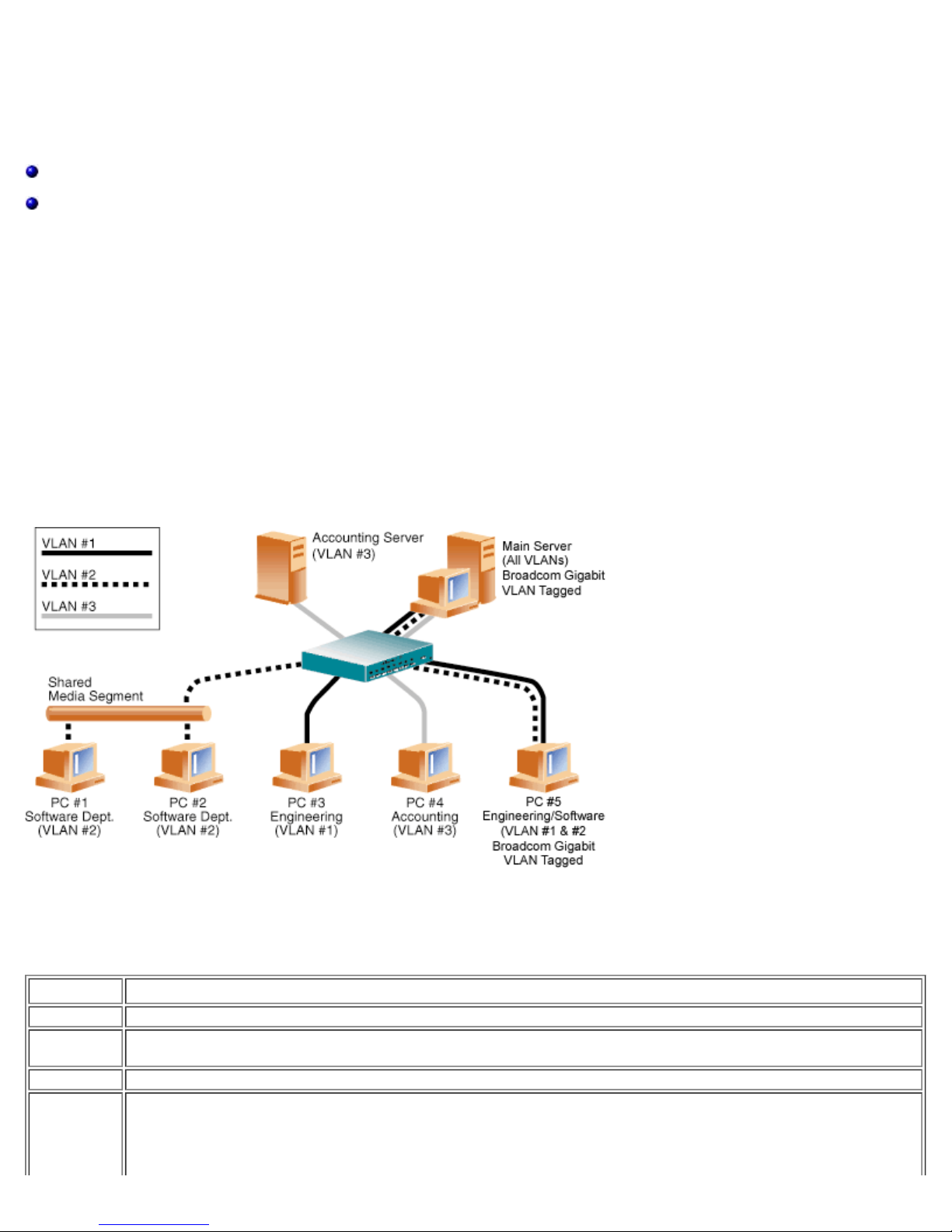
Figure 1: Example of Servers Supporting Multiple VLANs with Tagging
Figure 1 shows an example network that uses VLANs. In this example network, the physical LAN consists of a switch, two
servers, and five clients. The LAN is logically organized into three different VLANs, each representing a different IP subnet.
The features of this network are described in Table 1.
Table 1: Example VLAN Network Topology
Component Description
VLAN #1 An IP subnet consisting of the Main Server, PC #3, and PC #5. This subnet represents an engineering group.
VLAN #2
VLAN #3 Includes the Main Server, the Accounting Server and PC #4. This VLAN is an accounting group.
Main Server
file:///T|/htdocs/NETWORK/BroadCom/71921/NetXtremeII/en/vlan.htm[9/26/2012 3:28:33 PM]
Includes the Main Server, PCs #1 and #2 via shared media segment, and PC #5. This VLAN is a software
development group.
A high-use server that needs to be accessed from all VLANs and IP subnets. The Main Server has a Broadcom
adapter installed. All three IP subnets are accessed via the single physical adapter interface. The server is
attached to one of the switch ports, which is configured for VLANs #1, #2, and #3. Both the adapter and the
connected switch port have tagging turned on. Because of the tagging VLAN capabilities of both devices, the
Page 12

Virtual LANs: Broadcom NetXtreme II Network Adapter User Guide
separation between all of them.
Accounting
Server
PCs #1 and
#2
PC #3
PC #4
PC #5
NOTE: VLAN tagging is only required to be enabled on switch ports that create trunk links to other switches, or on ports
connected to tag-capable end-stations, such as servers or workstations with Broadcom adapters.
Available to VLAN #3 only. The Accounting Server is isolated from all traffic on VLANs #1 and #2. The switch
port connected to the server has tagging turned off.
Attached to a shared media hub that is then connected to the switch. PCs #1 and #2 belong to VLAN #2 only,
and are logically in the same IP subnet as the Main Server and PC #5. The switch port connected to this
segment has tagging turned off.
A member of VLAN #1, PC #3 can communicate only with the Main Server and PC #5. Tagging is not enabled
on PC #3 switch port.
A member of VLAN #3, PC #4 can only communicate with the servers. Tagging is not enabled on PC #4 switch
port.
A member of both VLANs #1 and #2, PC #5 has an Broadcom adapter installed. It is connected to switch port
#10. Both the adapter and the switch port are configured for VLANs #1 and #2 and have tagging enabled.
Adding VLANs to Teams
Each team supports up to 64 VLANs (63 tagged and 1 untagged). Note that only Broadcom adapters and Alteon® AceNIC
adapters can be part of a team with VLANs. With multiple VLANs on an adapter, a server with a single adapter can have a
logical presence on multiple IP subnets. With multiple VLANs in a team, a server can have a logical presence on multiple IP
subnets and benefit from load balancing and failover. For instructions on adding a VLAN to a team, see Adding a VLAN for
Windows operating systems.
NOTE: Adapters that are members of a failover team can also be configured to support VLANs. Because VLANs are not
supported for an Intel LOM, if an Intel LOM is a member of a failover team, VLANs cannot be configured for that team.
Please read all Restrictions and Disclaimers.
Back to Contents Page
file:///T|/htdocs/NETWORK/BroadCom/71921/NetXtremeII/en/vlan.htm[9/26/2012 3:28:33 PM]
Page 13

Manageability: Broadcom NetXtreme II Network Adapter User Guide
Back to Contents Page
Manageability: Broadcom NetXtreme II Network Adapter User
Guide
CIM
SNMP
HBA API
CIM
The Common Information Model (CIM) is an industry standard defined by the Distributed Management Task Force (DMTF).
Microsoft implements CIM on Windows server platforms. Broadcom will support CIM on Windows server platforms.
Broadcom's implementation of CIM will provide various classes to provide information to users through CIM client applications.
Note that Broadcom CIM data provider will provide data only, and users can choose their preferred CIM client software to
browse the information exposed by Broadcom CIM provider.
Broadcom CIM provider provides information through BRCM_NetworkAdapter and BRCM_ExtraCapacityGroup classes.
BRCM_NetworkAdapter class provides network adapter information pertaining to a group of adapters including Broadcom and
other vendors' controllers. BRCM_ExtraCapacityGroup class provides team configuration for the Broadcom Advanced Server
Program. Current implementation will provide team information and information of physical network adapters in the team.
Broadcom Advanced Server Program provides events through event logs. Users can use the "Event Viewer" provided by
Windows server platforms, or use CIM to inspect or monitor these events. Broadcom CIM provider will also provide event
information through the CIM generic event model. These events are __InstanceCreationEvent, __InstanceDeletionEvent and
__InstanceModificationEvent, and are defined by CIM. CIM requires the client application to register the events from the client
application, using queries as examples shown below in order to receive events properly.
SELECT * FROM __InstanceModificationEvent
where TargetInstance ISA "BRCM_NetworkAdapter"
SELECT * FROM __InstanceModificationEvent
where TargetInstance ISA "BRCM_ExtraCapacityGroup"
SELECT * FROM __InstanceCreationEvent
where TargetInstance ISA "BRCM_NetworkAdapter"
SELECT * FROM __InstanceDeletionEvent
where TargetInstance ISA "BRCM_NetworkAdapter"
SELECT * FROM __InstanceCreationEvent
where TargetInstance ISA "BRCM_ActsAsSpare"
SELECT * FROM __InstanceDeletionEvent
where TargetInstance ISA "BRCM_ActsAsSpare"
For detailed information about these events, see the CIM documentation at
http://www.dmtf.org/sites/default/files/standards/documents/DSP0004V2.3_final.pdf.
Broadcom also implements the Storage Management Initiative-Specification (SMI-S), which defines CIM management profiles
for storage systems.
SNMP
BASP Subagent
The BASP subagent, baspmgnt.dll, is designed for the Windows Server 2008 and Windows Server 2008 R2 SNMP service. It is
required to install the SNMP service before installing the BASP subagent.
The BASP subagent allows an SNMP manager software to actively monitor the configurations and performance of the
Broadcom Advanced Server features. The subagent also provides an alarm trap to an SNMP manager to inform the manager
of any changes to the conditions of the BASP component.
The BASP subagent allows monitoring of the configurations and statistics for the BASP teams, the physical NIC adapters
participating in a team, and the virtual NIC adapters created as the result of teaming. Non-teamed NIC adapters are not
monitored at this time. The BASP configuration data includes information such as team IDs, physical/virtual/VLAN/team
adapter IDs, physical/virtual/VLAN/team/ adapter descriptions, and MAC addresses of the adapters.
file:///T|/htdocs/NETWORK/BroadCom/71921/NetXtremeII/en/manage.htm[9/26/2012 3:28:35 PM]
Page 14

Manageability: Broadcom NetXtreme II Network Adapter User Guide
The statistics include detailed information such as data packets transmitted and received for the physical/virtual/VLAN/team
adapters.
The alarm trap forwards information about the changes in configuration of the physical adapters participating in a team, such
as physical adapter link up/down, and adapter installed/removed events.
To monitor this information, an SNMP manager must load the Broadcom BASP MIB database files to allow monitoring of the
information described above. These files, which are shown below, are included with the driver source media.
baspcfg.mib
baspstat.mib
basptrap.mib
HBA API
Broadcom supports the Storage Networking Industry Association (SNIA) Common HBA API on Windows and Linux operating
systems. The Common HBA API is an application program interface for the management of Fibre Channel Host Bus Adapters.
BASP Extensible-Agent
The Broadcom NetXtreme II Gigabit Ethernet Controller Extended Information SNMP extensible-agent (bcmif.dll) is designed
for Windows Server 2008 SNMP service.
The extensible-agent allows the SNMP manager software to actively monitor the configurations of the Broadcom NetXtreme II
adapter. It is intended to supplement the information already provided by the standard SNMP Management Network Interface
information.
The extensible-agent provides in-depth information about a Broadcom NetXtreme II adapter such as:
MAC address
Bound IP address
IP subnet mask
Physical link status
Adapter state
Line speed
Duplex mode
Memory range
Interrupt setting
Bus number
Device number
Function number
To monitor this information, a SNMP manager needs to load the Broadcom Extended information MIB file to allow monitoring
of the information described above. This file, bcmif.mib, is included on the installation CD.
The monitored workstation requires the installation of the Broadcom Extended Information SNMP extensible-agent, bcmif.dll,
and requires the Microsoft Windows Server 2008 SNMP service to be installed and loaded.
Please read all Restrictions and Disclaimers.
Back to Contents Page
file:///T|/htdocs/NETWORK/BroadCom/71921/NetXtremeII/en/manage.htm[9/26/2012 3:28:35 PM]
Page 15

Installing the Hardware: Broadcom NetXtreme II Network Adapter User Guide
Back to Contents Page
Installing the Hardware: Broadcom NetXtreme II Network
Adapter User Guide
Overview
System Requirements
Safety Precautions
Preinstallation Checklist
Installation of the Add-In NIC
Overview
This section applies to Broadcom NetXtreme II add-in network interface cards.
System Requirements
Before you install a Broadcom NetXtreme II adapter, verify that your system meets the following hardware and operating
system requirements:
Hardware Requirements
IA32- or EMT64-based computer that meets operating system requirements
One open slot: PCI Express 1.0a x4 or PCI Express Gen2 x8
128-MB RAM (minimum)
Operating System Requirements
General
PCI Express v1.0a, x4 (or greater) Host Interface
Microsoft Windows
One of the following versions of Microsoft Windows:
Windows Server 2008 family
Windows Server 2008 R2 family
Novell NetWare
Novell NetWare 6.5 with the latest support pack.
Linux
Although the adapter driver should work with many Linux kernel versions and distributions, it has only been tested on 2.4x
kernels (starting from 2.4.24) and 2.6.x kernels. The driver may not compile on kernels older than 2.4.24. Testing is
concentrated on i386 and x86_64 architectures. Only limited testing has been done on other architectures. Minor changes to
some source files and Makefile may be needed on some kernels.
VMware ESX
VMware ESX
file:///T|/htdocs/NETWORK/BroadCom/71921/NetXtremeII/en/install.htm[9/26/2012 3:28:37 PM]
Page 16

Installing the Hardware: Broadcom NetXtreme II Network Adapter User Guide
VMware ESX 3.5
7. Close the system case and disconnect any personal antistatic devices.
VMware ESX 4.0
VMware ESX 4.1
VMware ESX 5.0
Safety Precautions
CAUTION! The adapter is being installed in a system that operates with voltages that can be lethal. Before
you open the case of your system, observe the following precautions to protect yourself and to prevent damage
to the system components.
Remove any metallic objects or jewelry from your hands and wrists.
Make sure to use only insulated or nonconducting tools.
Verify that the system is powered OFF and is unplugged before you touch internal components.
Install or remove adapters in a static-free environment. The use of a properly grounded wrist strap or other
personal antistatic devices and an antistatic mat is strongly recommended.
Preinstallation Checklist
1. Verify that your system meets the hardware and software requirements listed under System Requirements.
2. Verify that your system is using the latest BIOS.
NOTE: If you acquired the adapter software on a disk or from the Dell support website (http://support.dell.com),
verify the path to the adapter driver files.
3. If your system is active, shut it down.
4. When system shutdown is complete, turn off the power and unplug the power cord.
5. Remove the adapter from its shipping package and place it on an antistatic surface.
6. Check the adapter for visible signs of damage, particularly on the edge connector. Never attempt to install a damaged
adapter.
Installation of the Add-In NIC
The following instructions apply to installing the Broadcom NetXtreme II adapter (add-in NIC) in most systems. Refer to the
manuals that were supplied with your system for details about performing these tasks on your particular system.
Installing the Add-In NIC
1. Review Safety Precautions and Preinstallation Checklist. Before you install the adapter, ensure that the system power is
OFF, the power cord is unplugged from the power outlet, and that you are following proper electrical grounding
procedures.
2. Open the system case and select the slot based on the adapter: PCI Express 1.0a x4, PCI Express Gen2 x8, or other
appropriate slot. A lesser width adapter can be seated into a greater width slot (x1 in a x4), but a greater width adapter
cannot be seated into a lesser width slot (x4 in a x1). If you do not know how to identify a PCI Express slot, refer to
your system documentation.
3. Remove the blank cover-plate from the slot that you selected.
4. Align the adapter connector edge with the PCI Express connector slot in the system.
5. Applying even pressure at both corners of the card, push the adapter card into the slot until it is firmly seated. When
the adapter is properly seated, the adapter port connectors are aligned with the slot opening, and the adapter faceplate
is flush against the system chassis.
CAUTION! Do not use excessive force when seating the card, as this may damage the system or the
adapter. If you have difficulty seating the adapter, remove it, realign it, and try again.
6. Secure the adapter with the adapter clip or screw.
file:///T|/htdocs/NETWORK/BroadCom/71921/NetXtremeII/en/install.htm[9/26/2012 3:28:37 PM]
Page 17

Installing the Hardware: Broadcom NetXtreme II Network Adapter User Guide
Connecting the Network Cables
The Broadcom NetXtreme II adapter has either an RJ-45 connector used for attaching the system to an Ethernet copper-wire
segment or a fiber optic connector for attaching the system to an Ethernet fiber optic segment.
NOTE: This section does not apply to blade servers.
Copper Wire
NOTE: The Broadcom NetXtreme II adapter supports Automatic MDI Crossover (MDIX), which eliminates the need for
crossover cables when connecting machines back-to-back. A straight-through Category 5 cable allows the machines to
communicate when connected directly together.
1. Select an appropriate cable. Table 1 lists the copper cable requirements for connecting to 10/100/1000BASE-T and
10GBASE-T ports:
Table 1: 10/100/1000BASE-T and 10GBASE-T Cable Specifications
Port Type Connector Media Maximum Distance
10BASE-T RJ-45 Category 3, 4, or 5 unshielded twisted pairs (UTP) 100m (328 ft)
100/1000BASE-T
1
RJ-45
Category 5
2
UTP
100m (328 ft)
10GBASE-T RJ-45
Category 63 UTP
Category 6A3 UTP
1
1000BASE-T signaling requires four twisted pairs of Category 5 balanced cabling, as specified in ISO/IEC
11801:2002 and ANSI/EIA/TIA-568-B.
2
Category 5 is the minimum requirement. Category 5e and Category 6 are fully supported.
3
10GBASE-T signaling requires four twisted pairs of Category 6 or Category 6A (augmented Category 6) balanced
cabling, as specified in ISO/IEC 11801:2002 and ANSI/TIA/EIA-568-B.
2. Connect one end of the cable to the RJ-45 connector on the adapter.
3. Connect the other end of the cable to an RJ-45 Ethernet network port.
Please read all Restrictions and Disclaimers.
Back to Contents Page
50m (164 ft)
100m (328 ft)
file:///T|/htdocs/NETWORK/BroadCom/71921/NetXtremeII/en/install.htm[9/26/2012 3:28:37 PM]
Page 18

Broadcom Boot Agent Driver Software: Broadcom NetXtreme II Network Adapter User Guide
Back to Contents Page
Broadcom Boot Agent Driver Software: Broadcom NetXtreme II
Network Adapter User Guide
Overview
Setting Up MBA in a Client Environment
Setting Up MBA in a Server Environment
Overview
Broadcom NetXtreme II adapters support Preboot Execution Environment (PXE), Remote Program Load (RPL), iSCSI, and
Bootstrap Protocol (BootP). Multi-Boot Agent (MBA) is a software module that allows your network computer to boot with the
images provided by remote servers across the network. The Broadcom MBA driver complies with the PXE 2.1 specification and
is released with both monolithic and split binary images. This provides flexibility to users in different environments where the
motherboard may or may not have built-in base code.
The MBA module operates in a client/server environment. A network consists of one or more boot servers that provide boot
images to multiple computers through the network. The Broadcom implementation of the MBA module has been tested
successfully in the following environments:
Linux Red Hat PXE Server. Broadcom PXE clients are able to remotely boot and use network resources (NFS mount,
and so forth) and to perform Linux installations. In the case of a remote boot, the Linux universal driver binds seamlessly
with the Broadcom Universal Network Driver Interface (UNDI) and provides a network interface in the Linux remotelybooted client environment.
Intel APITEST. The Broadcom PXE driver passes all API compliance test suites.
MS-DOS UNDI. The MS-DOS Universal Network Driver Interface (UNDI) seamlessly binds with the Broadcom UNDI to
provide a network adapter driver interface specification (NDIS2) interface to the upper layer protocol stack. This allows
computers to connect to network resources in an MS-DOS environment.
Windows Deployment Service (WDS). To extend functionalities beyond basic network connectivity when loading an
operating system through WDS, see Using the NetXtreme II Monolithic Driver.
Automated Deployment Service (ADS). To extend functionalities beyond basic network connectivity when loading an
operating system through ADS, see Using the NetXtreme II Monolithic Driver.
Setting Up MBA in a Client Environment
Setting up MBA in a client environment involves the following steps:
1. Enabling the MBA driver.
2. Configuring the MBA driver.
3. Setting up the BIOS for the boot order.
Enabling the MBA Driver
To enable or disable the MBA driver:
1. Insert an MS-DOS 6.22 or Dell Real Mode Kernel bootable disk containing the uxdiag.exe file (for 10/100/1000-Mbps
network adapters) or uediag.exe (for 10-Gbps network adapters) in the removable disk drive and power up your system.
NOTE: The uxdiag.exe (or uediag.exe) file is on the installation CD or in the DOS Utilities package available from
http://support.dell.com/.
1. Type:
uxdiag -mba [ 0-disable | 1-enable ] -c devnum
(or uediag -mba [ 0-disable | 1-enable ] -c devnum)
where
devnum is the specific device(s) number (0,1,2, ...) to be programmed.
file:///T|/htdocs/NETWORK/BroadCom/71921/NetXtremeII/en/pxe.htm[9/26/2012 3:28:39 PM]
Page 19

Broadcom Boot Agent Driver Software: Broadcom NetXtreme II Network Adapter User Guide
lang=eng&ProductFamily=Network+Connectivity&ProductLine=Boot+Agent+Software&ProductProduct=Intel%c2%ae+Boot+Agent
Configuring the MBA Driver
This section pertains to configuring the MBA driver on add-in NIC models of the Broadcom network adapter. For configuring the
MBA driver on LOM models of the Broadcom network adapter, check your system documentation.
NOTE: You can use the MBA Configuration Menu to configure the MBA driver one adapter at a time as described below, or
you can use the Broadcom NetXtreme II User Diagnostics MS-DOS based application to simultaneously configure the MBA driver
for multiple adapters.
1. Restart your system.
2. Press CTRL+S within 4 seconds after you are prompted to do so.
NOTE: The message prompting you to press CTRL+S is displayed once for each Broadcom NetXtreme II adapter you
have in your system that has MBA enabled. The messages are displayed in the same order as the assigned adapter
device number.
3. Use the UP ARROW and DOWN ARROW keys to move to the Boot Protocol menu item. Then use the RIGHT ARROW or
LEFT ARROW key to select the boot protocol of choice if other boot protocols besides Preboot Execution Environment
(PXE) are available. If available, other boot protocols include Remote Program Load (RPL), iSCSI, and Bootstrap Protocol
(BOOTP).
NOTE: For iSCSI boot-capable LOMs, the boot protocol is set via the BIOS. See your system documentation for more
information.
NOTE: If you have multiple adapters in your system and you are unsure which adapter you are configuring, press
CTRL+F6, which causes the port LEDs on the adapter to start blinking.
4. Use the UP ARROW, DOWN ARROW, LEFT ARROW, and RIGHT ARROW keys to move to and change the values for other
menu items, as desired.
5. Press F4 to save your settings.
6. Press ESC when you are finished.
Setting Up the BIOS
To boot from the network with the MBA, make the MBA enabled adapter the first bootable device under the BIOS. This
procedure depends on the system BIOS implementation. Refer to the user manual for the system for instructions.
Setting Up MBA in a Server Environment
Red Hat Linux PXE Server
The Red Hat Enterprise Linux distribution has PXE Server support. It allows users to remotely perform a complete Linux
installation over the network. The distribution comes with the boot images boot kernel (vmlinuz) and initial ram disk (initrd),
which are located on the Red Hat disk#1:
/images/pxeboot/vmlinuz
/images/pxeboot/initrd.img
Refer to the Red Hat documentation for instructions on how to install PXE Server on Linux.
The Initrd.img file distributed with Red Hat Enterprise Linux, however, does not have a Linux network driver for the Broadcom
NetXtreme II adapters. This version requires a driver disk for drivers that are not part of the standard distribution. You can
create a driver disk for the Broadcom NetXtreme II adapter from the image distributed with the installation CD. Refer to the
Linux Readme.txt file for more information.
MS-DOS UNDI/Intel APITEST
To boot in MS-DOS mode and connect to a network for the MS-DOS environment, download the Intel PXE PDK from the Intel
website. This PXE PDK comes with a TFTP/ProxyDHCP/Boot server. The PXE PDK can be downloaded from Intel at
http://downloadcenter.intel.com/SearchResult.aspx?
.
file:///T|/htdocs/NETWORK/BroadCom/71921/NetXtremeII/en/pxe.htm[9/26/2012 3:28:39 PM]
Page 20

Broadcom Boot Agent Driver Software: Broadcom NetXtreme II Network Adapter User Guide
Please read all Restrictions and Disclaimers.
Back to Contents Page
file:///T|/htdocs/NETWORK/BroadCom/71921/NetXtremeII/en/pxe.htm[9/26/2012 3:28:39 PM]
Page 21

NDIS2 Driver Software: Broadcom NetXtreme II Network Adapter User Guide
Back to Contents Page
NDIS2 Driver Software: Broadcom NetXtreme II Network
Adapter User Guide
Overview
Preinstallation Requirements
Installing the NDIS2 Driver Software for Use on MS-DOS Platforms
Using Keywords for the Drivers
Overview
Two drivers are discussed in this section:
BXND20X: Broadcom NetXtreme II Gigabit Ethernet driver
BNX2EV: Broadcom NetXtreme II 10 Gigabit Ethernet driver
The examples used in this section refer to the BXND20X driver, but also apply to the BNX2EV driver.
Preinstallation Requirements
Before you can successfully install the NDIS2 driver software, the Broadcom network adapter must be physically installed in
the server. Networking software that is appropriate to the operating system (such as Microsoft LAN Manager 2.2 for MS-DOS)
must already be running on your server.
Installing the NDIS2 Driver Software for Use on MS-DOS Platforms
The NDIS2 driver software can be run from an MS-DOS startup disk using Microsoft Network Client 3.0 or from the hard disk
using Microsoft LAN Manager 2.2.
Creating a Startup Disk to Run Microsoft Network Client
To perform this installation you must have the following items
Windows NT Server 4.0 CD-ROM
A blank MS-DOS system disk (3.5" high-density floppy disk)
Access to the Broadcom NDIS2 driver file (BXND20X.dos). This file is located on the driver source media.
NOTES:
Windows NT Server 4.0 users. When running Setup for Microsoft Network Client v3.0 for MS-DOS, click any
network card from the list (NE2000 Compatible, for example) to create the startup disk.
After creating the startup disk, follow the instructions in Modifying the Startup Disk.
To create a startup disk
1. Create a folder called NCADMIN in the root of the C drive.
2. Copy the NCADMIN.CN_, NCADMIN.EX_, and NCADMIN.HL_ files from the I386 folder on the Windows NT Server 4.0
CD-ROM.
3. Open a command prompt window and change the directory to C:\NCADMIN.
4. Type expand -r ncadmin.* and press ENTER.
5. Close the command prompt window by typing exit and then pressing ENTER.
6. Start Windows Explorer.
7. Open the NCADMIN folder and double-click ncadmin.exe.
file:///T|/htdocs/NETWORK/BroadCom/71921/NetXtremeII/en/ndis2.htm[9/26/2012 3:28:41 PM]
Page 22

NDIS2 Driver Software: Broadcom NetXtreme II Network Adapter User Guide
8. Follow the on-screen instructions to make the network startup disk (choose NE2000 Compatible from the list of
adapters).
Modifying the Startup Disk
To modify the startup disk
1. Edit A:\Net\Protocol.ini with Notepad or a similar text editor.
a. Change DriverName=$ to DriverName=BXND20X$.
b. Remove all other parameter entries under the [MS$NE2CLONE] or equivalent section such as IOBASE=0x300 or
INTERRUPT=3, and so on.
Example Protocol.ini file for IP
[network.setup]
version=0x3110
netcard=ms$ne2clone,1,MS$NE2CLONE,1
transport=tcpip,TCPIP
lana0=ms$ne2clone,1,tcpip
[MS$NE2CLONE]
DriverName=BXND20X$
[protman]
DriverName=PROTMAN$
PRIORITY=MS$NDISHLP
[tcpip]
NBSessions=6
DefaultGateway=0
SubNetMask=255 0 0 0
IPAddress=192 168 0 1
DisableDHCP=0
DriverName=TCPIP$
BINDINGS=MS$NE2CLONE
LANABASE=0
Example Protocol.ini file for IPX
[network.setup]
version=0x3110
netcard=ms$ne2clone,1,MS$NE2CLONE,1
transport=ms$ndishlp,MS$NDISHLP
transport=ms$nwlink,MS$NWLINK
lana0=ms$ne2clone,1,ms$nwlink
lana1=ms$ne2clone,1,ms$ndishlp
[MS$NE2CLONE]
DriverName=BXND20X$
[protman]
DriverName=PROTMAN$
PRIORITY=MS$NDISHLP
[MS$NDISHLP]
DriverName=ndishlp$
BINDINGS=ms$ne2clone
[ms$nwlink]
DriverName=nwlink$
FRAME=Ethernet_802.2
BINDINGS=MS$NE2CLONE
LANABASE=0
Example Protocol.ini file for NetBEUI
[network.setup]
version=0x3110
netcard=ms$ne2clone,1,MS$NE2CLONE,1
transport=ms$ndishlp,MS$NDISHLP
transport=ms$netbeui,MS$NETBEUI
lana0=ms$ne2clone,1,ms$ndishlp
lana1=ms$ne2clone,1,ms$netbeui
[MS$NE2CLONE]
DriverName=BXND20X$
[protman]
DriverName=PROTMAN$
PRIORITY=MS$NDISHLP
[MS$NDISHLP]
DriverName=ndishlp$
BINDINGS=MS$NE2CLONE
[MS$NETBEUI]
DriverName=netbeui$
SESSIONS=10
NCBS=12
BINDINGS=MS$NE2CLONE
LANABASE=0
2. Edit A:\Net\System.ini.
a. Change netcard= to netcard=BXND20X.dos.
b. Check for references to C:\NET and change C:\NET to A:\NET if necessary.
file:///T|/htdocs/NETWORK/BroadCom/71921/NetXtremeII/en/ndis2.htm[9/26/2012 3:28:41 PM]
Page 23

NDIS2 Driver Software: Broadcom NetXtreme II Network Adapter User Guide
Example System.ini file
[network]
sizworkbuf=1498
filesharing=no
printsharing=no
autologon=yes
computername=MYPC
lanroot=A:\NET
username=USER1
workgroup=WORKGROUP
reconnect=yes
dospophotkey=N
lmlogon=0
logondomain=
preferredredir=basic
autostart=basic
maxconnections=8
[network drivers]
netcard=BXND20X.dos
transport=ndishlp.sys,*netbeui
devdir=A:\NET
LoadRMDrivers=yes
3. Copy BXND20X.dos to A:\Net.
4. Create the appropriate Autoexec.bat file in drive A for the chosen protocol as shown below.
For TCP/IP
path=a:\net
a:\net\net initialize
a:\net\netbind.com
a:\net\umb.com
a:\net\tcptsr.exe
a:\net\tinyrfc.exe
a:\net\nmtsr.exe
a:\net\emsbfr.exe
a:\net\net start basic
net use z: \\SERVERNAME\SHARENAME
For IPX
SET PATH=A:\NET
A:\NET\net initialize
A:\NET\nwlink
A:\NET\NET START BASIC
net use z: \\SERVERNAME\SHARENAME
For NetBEUI
SET PATH=A:\NET
A:\NET\NET START BASIC
net use z: \\SERVERNAME\SHARENAME
5. Create a Config.sys file on the startup disk in drive A as shown below.
files=30
device=a:\net\ifshlp.sys
lastdrive=z
Installing the DOS NDIS2 Driver Software on the Hard Disk
To install the DOS NDIS2 Driver Software on the hard disk
1. Verify that the system has Microsoft LAN Manager 2.2 installed, with a protocol such as NetBEUI configured.
2. Create a folder on your hard disk to store the NDIS 2.01 driver.
Example: C:\LANMAN
3. Copy the BXND20X.dos file to this folder.
Edit the Config.sys file by adding the following lines:
DEVICE = C:\LANMAN\PROTMAN.DOS
DEVICE = C:\LANMAN\BXND20X.DOS
DEVICE = C:\LANMAN\NETBEUI.DOS
4. Edit the Autoexec.bat file by adding the following lines:
C:\ LANMAN\NETBIND.EXE
C:\LANMAN\NET START WORKSTATION
C:\LANMAN\NET USE drive letter: \\server name\resource name
5. Edit the Protocol.ini file (located in C:\LANMAN) to configure the driver to bind with NetBEUI or any other protocols.
Example:
[PROTOCOL MANAGER]
DriverName = PROTMAN$
file:///T|/htdocs/NETWORK/BroadCom/71921/NetXtremeII/en/ndis2.htm[9/26/2012 3:28:41 PM]
Page 24

NDIS2 Driver Software: Broadcom NetXtreme II Network Adapter User Guide
[NETBEUI_XIF]
DriverName = netbeui$
BINDINGS = BXND20X
[BXND20X]
DriverName = "BXND20X$"
6. Restart the computer to complete the installation.
NOTE: The driver loads during system configuration and displays the Broadcom banner, controller name, MAC
address, IRQ number, detected line speed, and the controller BusNum and DevNum. If the driver fails to load, an
initialization fail message is displayed.
Using Keywords for the Drivers
The Protocol.ini file contains certain keywords that are used by the BXND20X.dos AND BXND20X.dos drivers. These keywords
are listed below:
BusNum. Specifies the number of the PCI bus on which the network adapter is located. Requires a decimal number having a
value ranging from 0 to 255.
DevNum. Specifies the device number assigned to the network adapter when it is configured by the PCI BIOS. Requires a
decimal number having a value ranging from 0 to 255.
FuncNum or PortNum. Specifies the PCI function or port number assigned to the network controller. Requires a decimal
number having a value ranging from 0 to 7.
NOTE: These keywords, BusNum, DevNum, and FuncNum (or PortNum) are needed when multiple adapters are
installed in the server and when a specific controller must be loaded in a certain order. These keywords are used concurrently
and are included for manufacturing purposes. Do not use them unless you are familiar with how to configure PCI devices. A
PCI device scan utility is needed to find this information.
LineSpeed. Specifies the speed of the network connection in Mbit/s. Requires the decimal number 10, 100, or 1000.
Technically, a line speed of 1000 Mbit/s cannot be forced and is achievable only through auto-negotiation. For the sake of
simplicity, the driver performs auto-negotiation when the line speed is set to a value of 1000.
NOTE: LineSpeed is not available with the Broadcom NetXtreme II 10 Gigabit Ethernet driver.
Duplex. Specifies the duplex mode of the network adapter. Requires a setting of either Half or Full. When this keyword is
used, the LineSpeed keyword must also be used. If neither keyword is used, the network adapter defaults to autonegotiation mode.
NOTE: LineSpeed is not available with the Broadcom NetXtreme II 10 Gigabit Ethernet driver.
NodeAddress. Specifies the network address used by the network adapter. If a multicast address or a broadcast address is
specified, the adapter uses the default MAC address.
Example:
[BXND20X]
DriverName = "BXND20X$"
BusNum = 3
DevNum = 14
PortNum = 2
LineSpeed = 1000
Duplex = Full
NodeAddress = 001020304050
FixCheckSumOff. Turns off the driver's workaround for the TCP/IP stack to recognize the 1s complemented version of the
checksum.
AcceptAllMC. Informs the driver to deliver all multicast packets to the upper protocol.
Please read all Restrictions and Disclaimers.
Back to Contents Page
file:///T|/htdocs/NETWORK/BroadCom/71921/NetXtremeII/en/ndis2.htm[9/26/2012 3:28:41 PM]
Page 25

ODI Driver Software: Broadcom NetXtreme II Network Adapter User Guide
Back to Contents Page
ODI Driver Software: Broadcom NetXtreme II Network Adapter
User Guide
Overview
ODI Client32
DOS ODI
Overview
Three drivers are discussed in this section:
BX2.LAN: Broadcom NetXtreme II Gigabit Ethernet 32-bit driver
BX2.COM: Broadcom NetXtreme II Gigabit Ethernet 16-bit driver
BNX2EV.COM: Broadcom NetXtreme II 10 Gigabit Ethernet 16-bit driver
The examples used in the ODI Client32 section only refer to the BX2.LAN driver. The examples used in the DOS ODI section
refer to the BX2.COM driver, but also apply to the BNX2EV.COM driver.
ODI Client32
The Open Data-Link Interface (ODI) driver software allows LAN drivers to work together irrespective of differences between
the hardware and/or the protocol stacks of communicating systems. An intervening layer, called the link support layer (LSL),
is responsible for routing different packet types between local area network (LAN) drivers and protocol stacks.
Installing the Driver Software
The ODI Driver software must be installed on a system having an MS-DOS operating system. MS-DOS 6.22 is recommended.
Preinstallation Requirements
1. Copy the Broadcom ODI driver files to a floppy disk. Copy the BX2.LAN and BX2.LDI files for the Client32 driver.
2. Go to the Novell web site http://www.novell.com/coolsolutions/tools/13555.html and download the NetWare DOS Client
files to the hard disk: download the dw271e.zip file for the Client32 installation.
Installing the Novell NetWare Client32 Driver for MS-DOS
1. Extract the dw271.zip file to a temporary directory on the hard disk.
2. Double-click the dw271e.exe file.
3. Type y and then press ENTER when you are prompted for a response.
4. Restart your system in MS-DOS mode.
5. Change to the directory where the extracted files are located.
6. Type install, and then press ENTER.
7. Read the agreement, and then press ENTER to accept the agreement.
8. Using the UP ARROW or DOWN ARROW key as necessary, highlight Novell Client for DOS (required), and then
press F10 to save and continue.
9. Highlight 32-bit LAN Drivers, and then press F10 to save and continue.
10. Insert the floppy disk containing the Broadcom 32-bit LAN driver files into the floppy disk drive.
11. Highlight USER SPECIFIED 32-BIT DRIVER, and then press ENTER.
12. Press ENTER.
13. Highlight the NetXtreme II Gigabit Ethernet Driver, and then press ENTER.
file:///T|/htdocs/NETWORK/BroadCom/71921/NetXtremeII/en/dosodi.htm[9/26/2012 3:28:43 PM]
Page 26

ODI Driver Software: Broadcom NetXtreme II Network Adapter User Guide
14. Press ENTER.
Example keyword entries for the LineSpeed, and Duplex keywords are shown below:
15. Select Receive Buffers, type 32 for the value, and then press F10 to save and continue.
16. Press F10 to save and continue. The Bx2.LAN and Bx2.LDI files are copied to the directory.
17. Restart the system to complete the install.
18. As the files are being loaded, the system attempts to attach to a NetWare server using the frame types specified in
19. Change to drive F and log on to the NetWare server.
NOTE: Do not change the default settings for any of the other items in the Installation Configuration Summary.
Net.cfg. If the connection is successful, a dialog box is displayed.
NOTE: The driver loads during system configuration, and the Broadcom banner, the adapter name, the MAC
address, the IRQ number, the detected line speed, and the bus number (BusNum) and device number (DevNum) of the
adapter are displayed. If the driver fails to load, an initialization fail message appears.
Configuring the Driver Software
The ODI driver software can be configured by adding specific optional keywords to the Net.cfg file.
If multiple (or multiport) Broadcom NetXtreme II adapters are installed in a system, the ODI driver software loads by default
on the adapter/port that has a good link. If two or more adapters have a good link, the ODI driver software loads on the
adapter having the latest Device ID. If two or more adapters that have a good link have the same Device ID, the ODI driver
software loads on the adapter that is located in the slot having the lowest bus number.
If it is necessary to have the ODI driver load on certain adapters in a certain order, the BusNum, DevNum, and FuncNum
keywords can be used. Do not use these keywords unless you know how to configure PCI devices.
The BusNum keyword value, which represents the PCI bus number in which the adapter is located, is a hexadecimal number
ranging from 0 to FF.
The FuncNum keyword value, which represents the function (port) number of a multiport adapter, is a hexadecimal number
with 0 representing the first port and 1 representing the second port.
The DevNum keyword value, which represents the assigned device number, is a hexadecimal number ranging from 0 to 1F.
NOTES:
At the end of the ODI driver software installation process, note the BusNum and DevNum values that are
displayed. Alternatively, use Broadcom Advanced Control Suite (see Viewing Resource Information) to view the
bus number, function (port) number, and device number assigned to each adapter (Windows users only).
The values for the BusNum, DevNum, and FuncNum keywords are displayed in hexadecimal notation when
the driver loads on the adapter.
Example BusNum, DevNum, and FuncNum keyword entries for loading the ODI driver on multiple adapters in
a certain order are shown below:
PROTOCOL <protocol name>
BIND BX2
BIND BX2
LINK DRIVER BX2
BUSNUM 1
DEVNUM 9
FRAME <frame #1 name>
LINK DRIVER BX2
BUSNUM 1
DEVNUM A
FRAME <frame #2 name>
The LineSpeed keyword is used to force the speed of the network connection. The LineSpeed keyword requires a decimal
number and of either 10, 100, or 1000. Technically, a line speed of 1000 Mbit/s cannot be forced and can be achieved only
through auto-negotiation. For the sake of simplicity, the driver performs auto-negotiation when the line speed is set to a
value of 1000.
The Duplex keyword is used to force the duplex mode of the adapter. The Duplex keyword requires a text string of either
HALF or FULL. When the Duplex keyword is used, the LineSpeed keyword must also be used. If neither keyword is used, the
network adapter defaults to auto-negotiation mode.
file:///T|/htdocs/NETWORK/BroadCom/71921/NetXtremeII/en/dosodi.htm[9/26/2012 3:28:43 PM]
Page 27

ODI Driver Software: Broadcom NetXtreme II Network Adapter User Guide
address, the IRQ number, the detected line speed, and the BUSNUM and DEVNUM of the adapter are displayed. If the
LINK DRIVER BX2
LINESPEED 100
DUPLEX FULL
DOS ODI
The Open Data-Link Interface (ODI) driver software allows LAN drivers to work together irrespective of differences between
the hardware and/or the protocol stacks of communicating computers. An intervening layer, called the link support layer
(LSL), is responsible for routing different packet types between LAN drivers and protocol stacks.
NOTE: The examples used in this section refer to the BX2.COM driver, but also apply to the BNX2EV.COM driver.
Installing the Driver Software
Installing the DOS/ODI driver software involves the following steps:
1. Verifying that the DOS 6.22 operating system files are installed on your computer hard disk or are available on a
removable storage device.
2. Installing the DOS/ODI driver software in the DOS environment.
3. If necessary, reconfiguring the driver software after installation.
Preinstallation Requirements
1. Verify that the Broadcom Ethernet adapter driver software has been installed on your computer and install it if it has
not (see Installing the Driver Software). Otherwise, you cannot use a Broadcom Ethernet adapter in the DOS
environment.
NOTE: To successfully install the adapter driver for DOS, the adapter must be installed in the computer before you
install the driver.
2. Install the DOS 6.22 files on your computer hard disk or have them available on a removable storage device.
Installing the DOS ODI Driver on DOS 6.22
1. Copy the DOS ODI driver file to the root directory of the hard disk.
2. Copy Lsl.com, Ipxodi.com, and Vlm.com to the same directory (these files are provided by Novell).
3. Edit the Autoexec.bat file by adding the following lines:
C:\LSL
C:\BX2
C:\IPXODI
C:\VLM
4. Edit the Net.cfg file and place the file in the same location as the Autoexec.bat file (located in drive C) to configure the
driver to bind with different frame types.
Example:
LINK DRIVER BX2
FRAME ETHERNET_802.2
FRAME ETHERNET_802.3
FRAME ETHERNET_II
FRAME ETHERNET_SNAP
NetWare DOS Requester
FIRST NETWORK DRIVE=F
NETWARE PROTOCOL=NDS BIND
PROTOCOL IPXODI
5. Restart the computer to complete the installation.
6. As the files are being loaded, the computer attempts to attach to a NetWare server using the frame types specified in
Net.cfg. If the connection is successful, a dialog box appears.
7. Change to drive F and log onto the NetWare server.
F: <enter>
F:\login admin <enter>
NOTE: The driver loads during system configuration, and the Broadcom banner, the adapter name, the MAC
file:///T|/htdocs/NETWORK/BroadCom/71921/NetXtremeII/en/dosodi.htm[9/26/2012 3:28:43 PM]
Page 28

ODI Driver Software: Broadcom NetXtreme II Network Adapter User Guide
driver fails to load, an initialization fail message appears.
Configuring Parameters for the BX2.com/BX2EV.COM Driver (in the Net.cfg file)
The following are optional custom keywords used in the Net.cfg file:
BUSNUM
DEVNUM
FUNNUM
SUBVID
MODEL
The first two keywords (BUSNUM and DEVNUM) are used together and have been included for manufacturing purposes. Do
not use them unless you are familiar with PCI device configuration. These two keywords are needed if multiple Broadcom
NetXtreme II adapters are installed on a system, and each adapter must be loaded in a specific order.
BUSNUM specifies the PCI bus number and DEVNUM specifies the device number that is assigned to the board when it is
configured by the PCI BIOS.
The values for these adapter parameters are displayed in hexadecimal notation when the driver loads (the Net.cfg file expects
hexadecimal values). A PCI device scan utility can also be used to find this information. If the driver loads on a single
adapter, the displayed values can be used in the Net.cfg file.
If a PCI scan utility displays card 1 at bus 4 and device 11 (hexadecimal), and card 3 at bus 3 and device 13 (hexadecimal),
the following load instructions are written to the Net.cfg file (load card 3 first, and optionally load card 1 second):
LINK DRIVER BX2
BUSNUM 3
DEVNUM 13 (13 hex = 19 decimal)
LINK DRIVER BX2
BUSNUM 4
DEVNUM 11 (11 hex = 17 decimal)
The FUNNUM keyword is used to determine which function/port the driver is to load on when using a multifunction
(multiport) adapter. Function number values are limited to 0 and 1, for the first and second function of the adapter.
The SUBVID keyword is used to for load the driver only on the first network interface card found that has a subvendor ID
(SVID) that matches the one set in Net.cfg. The driver ignores all other network interface cards that do not have a matching
SVID. SUBVID expects a hexadecimal number.
Example:
LINK DRIVER BX2
SUBVID 14E4
SUBVID cannot be used with BUSNUM, DEVNUM or FUNNUM.
The MODEL keyword is for loading the driver only on the first network interface card found that has a subvendor ID (SVID)
that matches the one set in MODEL. The driver ignores all other NICs that do not have a matching SVID. MODEL expects a
decimal number.
Example:
LINK DRIVER B44
MODEL 5348
Please read all Restrictions and Disclaimers.
Back to Contents Page
file:///T|/htdocs/NETWORK/BroadCom/71921/NetXtremeII/en/dosodi.htm[9/26/2012 3:28:43 PM]
Page 29

Linux Driver Software: Broadcom NetXtreme II Network Adapter User Guide
not support the reporting and configuration of NetXtreme II WOL settings via ethtool. For silicon revisions of B2 or later, the
Back to Contents Page
Linux Driver Software: Broadcom NetXtreme II Network Adapter
User Guide
Introduction
Limitations
Packaging
Installing Linux Driver Software
Unloading/Removing the Linux Driver
Patching PCI Files (Optional)
Network Installations
Setting Values for Optional Properties
Driver Defaults
Driver Messages
Teaming with Channel Bonding
Remote PHY Support
Statistics
Linux iSCSI Offload
Introduction
This section discusses the Linux drivers for the Broadcom NetXtreme II network adapters.
Table 1: Broadcom NetXtreme II Linux Drivers
Linux
Driver
bnx2
cnic
bnx2x Linux driver for the BCM57710/BCM57711/BCM57712 10 Gbps network adapters
bnx2i
Description
Linux drivers for the BCM5708/BCM5709 10/100/1000/2500 Mbps network adapters. The bnx2 driver is the
networking driver and the cnic driver supports additional features required by the bnx2i iSCSI offload driver.
Linux driver to enable iSCSI offload on the BCM5708/BCM5709/BCM57710/BCM57711/BCM57712
10/100/1000/2500/10000 Mbps network adapters
Limitations
bnx2 Driver
bnx2x Driver
bnx2i Driver
bnx2 Driver
The current version of the driver has been tested on all 2.6.x kernels. Testing is concentrated on i386 and x86_64
architectures. Only limited testing has been done on other architectures. Minor changes to some source files and Makefile may
be needed on some kernels. Additionally, the Makefile will not compile the cnic driver on kernels older than 2.6.16. iSCSI
offload is only supported on 2.6.16 and newer kernels.
NOTE: For Broadcom NetXtreme II BCM5708 devices with a silicon revision prior to B2, the open source bnx2 driver does
file:///T|/htdocs/NETWORK/BroadCom/71921/NetXtremeII/en/linux.htm[9/26/2012 3:28:46 PM]
Page 30

Linux Driver Software: Broadcom NetXtreme II Network Adapter User Guide
bnx2 driver reports support for Magic Packet WOL via ethtool. Enabling support via ethtool is mandatory to successfully wake
rpm -ivh netxtreme2-
.src.rpm
the system. To determine the silicon revision of your Broadcom NetXtreme II device, use the lspci command, where "10" =
revision B0, "11" = revision B1, and "12" = revision B2.
bnx2x Driver
The current version of the driver has been tested on 2.6.x kernels starting from 2.6.9. The driver may not compile on kernels
older than 2.6.9. Testing is concentrated on i386 and x86_64 architectures. Only limited testing has been done on some other
architectures. Minor changes to some source files and Makefile may be needed on some kernels.
bnx2i Driver
The current version of the driver has been tested on 2.6.x kernels, starting from 2.6.18 kernel. The driver may not compile
on older kernels. Testing is concentrated on i386 and x86_64 architectures, Red Hat EL5, and SUSE 11 SP1 distributions.
Packaging
The Linux driver is released in the packaging formats shown in Table 2. The netxtreme2 package contains the bnx2 (1 Gb
network adapter) driver, the bnx2x (10 Gb network adapter) driver, and the bnx2i (iSCSI) driver for source RPM and
compressed tar.
Table 2: Linux Driver Packaging
Format Drivers
Source RPM netxtreme2-version.src.rpm
Compressed tar netxtreme2-version.tar.gz
Source DKMS RPM netxtreme2-version.dkms.src.rpm
Binary DKMS RPM netxtreme2-version.dkms.noarch.rpm
Supplemental tar netxtreme2_sup-version.tar.gz
Source KMP RPM broadcom-netxtreme2-version.src.rpm
KMP RPM broadcom-netxtreme2-kmp-default-version.x86_64.rpm
KMP trace RPM broadcom-netxtreme2-kmp-trace-version.x86_64.rpm
KMP Xen RPM broadcom-netxtreme2-kmp-xen-version.x86_64.rpm
Identical source files to build the driver are included in both RPM and TAR source packages. The supplemental tar file contains
additional utilities such as patches and driver diskette images for network installation.
Updated open-iSCSI components are released in source RPM format.
netxtreme2-version.src.rpm: NetXtreme II L2/cnic/bnx2i driver source RPM.
netxtreme2-version.tar.gz: tar zipped NetXtreme II L2/cnic/bnx2i driver
Installing Linux Driver Software
Installing the Source RPM Package
Building the Driver from the Source TAR File
Installing the Binary DKMS RPM Driver Package
NOTE: If a bnx2/bnx2x/bnx2i driver is loaded and the Linux kernel is updated, the driver module must be recompiled if
the driver module was installed using the source RPM or the TAR package. This does not apply to the source DKMS RPM.
Installing the Source RPM Package
NOTE: The examples in this procedure refer to the bnx2 driver, but also apply to the bnx2x and bnx2i drivers.
1. Install the source RPM package:
version
file:///T|/htdocs/NETWORK/BroadCom/71921/NetXtremeII/en/linux.htm[9/26/2012 3:28:46 PM]
Page 31

Linux Driver Software: Broadcom NetXtreme II Network Adapter User Guide
2. Change the directory to the RPM path and build the binary driver for your kernel (the RPM path is different for different
Building the Driver from the Source TAR File
Linux distributions):
cd /usr/src/redhat,OpenLinux,turbo,packages,rpm ...
or
rpmbuild -bb SPECS/netxtreme2.spec (for RPM version 4.x.x)
NOTE: During your attempt to install a source RPM package, the following message may be displayed:
error: cannot create %sourcedir /usr/src/redhat/SOURCES
The most likely cause of the error is that the rpm-build package has not been installed. Locate the rpm-build
package on the Linux installation media and install it using the following command:
rpm -ivh rpm-build-version.arch.rpm
Complete the installation of the source RPM.
3. Install the newly built package (driver and man page):
rpm -ivh RPMS/i386/netxtreme2-version.arch.rpm
The --force option is needed if installing over an existing distribution that may already contain an older version of
the driver.
The driver is installed to the following path:
2.6.x kernels
/lib/modules/kernel_version/kernel/drivers/net/bnx2.ko
2.6.16 kernels and newer (bnx2 driver)
/lib/modules/kernel_version/kernel/drivers/net/bnx2.ko
/lib/modules/kernel_version/kernel/drivers/net/cnic.ko
2.6.16 kernels and newer (bnx2i driver)
/lib/modules/kernel_version/kernel/drivers/scsi/bnx2i/bnx2i.ko
4. Load the driver:
insmod bnx2.ko (on 2.6.x kernels)
or
modprobe bnx2
Verify that your network adapter supports iSCSI by checking the message log. If the message "bnx2i: dev eth0
does not support iSCSI" appears in the message log after loading the bnx2i driver, then iSCSI is not supported. This
message may not appear until the interface is opened, as with:
ifconfig eth0 up
5. Load the cnic driver (if applicable):
insmod cnic.ko
or
modprobe cnic
To configure the network protocol and address, refer to the documentation provided with your operating system.
Installing the KMP Package
NOTE: The examples in this procedure refer to the bnx2x driver, but also apply to the bnx2 and bnx2i drivers.
1. Install the KMP package:
rpm -ivh <file>
rmmod bnx2x
2. Load the driver:
modprobe bnx2x
file:///T|/htdocs/NETWORK/BroadCom/71921/NetXtremeII/en/linux.htm[9/26/2012 3:28:46 PM]
Page 32

Linux Driver Software: Broadcom NetXtreme II Network Adapter User Guide
NOTE: The examples used in this procedure refer to the bnx2 driver, but also apply to the bnx2x driver.
1. Create a directory and extract the TAR files to the directory:
tar xvzf netxtreme2-version.tar.gz
2. Build the driver bnx2.ko (or bnx2i.ko) as a loadable module for the running kernel:
cd netxtreme2-version
make
3. Test the driver by loading it (first unload the existing driver, if necessary):
rmmod bnx2 (or bnx2x, or bnx2i)
insmod bnx2/src/bnx2.ko (or bnx2x/src/bnx2x.ko, or bnx2i/src/bnx2i.ko)
Verify that your network adapter supports iSCSI by checking the message log. If the message "bnx2i: dev eth0
does not support iSCSI" appears in the message log after loading the bnx2i driver, then iSCSI is not supported. This
message may not appear until the interface is opened, as with:
ifconfig eth0 up
4. Load the cnic driver (if applicable):
insmod cnic.ko
5. Install the driver and man page:
make install
NOTE: See the RPM instructions above for the location of the installed driver.
6. Install the user daemon (brcm_iscsiuio).
Refer to Load and Run Necessary iSCSI Software Components for instructions on loading the software components required to
use the Broadcom iSCSI offload feature.
To configure the network protocol and address after building the driver, refer to the manuals supplied with your operating
system.
Installing the Binary DKMS RPM Driver Package
Dynamic Kernel Module Support (DKMS) is designed to simplify the rebuilding of modules whenever you upgrade the kernel.
This is accomplished by creating a framework where a kernel-dependent module source can reside.
To install the binary DKMS RPM driver package
1. Download the binary DKMS RPM (dkms-version.noarch.rpm) from http://linux.dell.com/dkms/.
2. Install the binary DKMS RPM package:
rpm -ivh dkms-version.noarch.rpm
3. Install the DKMS RPM driver package:
rpm -ivh netxtreme2-version dkms.noarch.rpm
Verify that your network adapter supports iSCSI by checking the message log. If the message "bnx2i: dev eth0
does not support iSCSI" appears in the message log after loading the bnx2i driver, then iSCSI is not supported. This
message may not appear until the interface is opened, as with:
ifconfig eth0 up
4. To use Broadcom iSCSI, refer to Load and Run Necessary iSCSI Software Components to load the necessary software
components.
For more information, go to http://linux.dell.com.
Load and Run Necessary iSCSI Software Components
The Broadcom iSCSI Offload software suite consists of three kernel modules and a user daemon. Required software
components can be loaded either manually or through system services.
1. Unload the existing driver, if necessary:
Manual:
rmmod bnx2i
2. Load the iSCSI driver:
file:///T|/htdocs/NETWORK/BroadCom/71921/NetXtremeII/en/linux.htm[9/26/2012 3:28:46 PM]
Page 33

Linux Driver Software: Broadcom NetXtreme II Network Adapter User Guide
bnx2/bnx2x driver may be needed. The driver disk images for the most recent Red Hat and SuSE versions are included. Boot
Manual:
insmod bnx2i.ko
or
modprobe bnx2i
Unloading/Removing the Linux Driver
Unloading/Removing the Driver from an RPM Installation
Removing the Driver from a TAR Installation
Unloading/Removing the Driver from an RPM Installation
NOTES:
The examples used in this procedure refer to the bnx2 driver, but also apply to the bnx2x driver.
On 2.6 kernels, it is not necessary to bring down the eth# interfaces before unloading the driver module.
If the cnic driver is loaded, unload the cnic driver before unloading the bnx2 driver.
Prior to unloading the bnx2i driver, disconnect all active iSCSI sessions to targets.
To unload the driver, use ifconfig to bring down all eth# interfaces opened by the driver, and then type the following:
rmmod bnx2
NOTE: The above command will also remove bnx2, bnx2x, and cnic modules.
If the driver was installed using RPM, do the following to remove it:
rpm -e netxtreme2
Removing the Driver from a TAR Installation
NOTE: The examples used in this procedure refer to the bnx2 driver, but also apply to the bnx2x and bnx2i drivers.
If the driver was installed using make install from the tar file, the bnx2.ko driver file has to be manually deleted from the
operating system. See Installing the Source RPM Package for the location of the installed driver.
Patching PCI Files (Optional)
NOTE: The examples used in this procedure refer to the bnx2 driver, but also apply to the bnx2x and bnx2i drivers.
For hardware detection utilities such as Red Hat kudzu to properly identify bnx2 supported devices, a number of files
containing PCI vendor and device information may need to be updated.
Apply the updates by running the scripts provided in the supplemental tar file. For example, on Red Hat Enterprise Linux,
apply the updates by doing the following:
./patch_pcitbl.sh /usr/share/hwdata/pcitable pci.updates
/usr/share/hwdata/pcitable.new bnx2
./patch_pciids.sh /usr/share/hwdata/pci.ids pci.updates
/usr/share/hwdata/pci.ids.new
Next, the old files can be backed up and the new files can be renamed for use.
cp /usr/share/hwdata/pci.ids /usr/share/hwdata/old.pci.ids
cp /usr/share/hwdata/pci.ids.new /usr/share/hwdata/pci.ids
cp /usr/share/hwdata/pcitable /usr/share/hwdata/old.pcitable
cp /usr/share/hwdata/pcitable.new /usr/share/hwdata/pcitable
Network Installations
For network installations through NFS, FTP, or HTTP (using a network boot disk or PXE), a driver disk that contains the
file:///T|/htdocs/NETWORK/BroadCom/71921/NetXtremeII/en/linux.htm[9/26/2012 3:28:46 PM]
Page 34

Linux Driver Software: Broadcom NetXtreme II Network Adapter User Guide
drivers for other Linux versions can be compiled by modifying the Makefile and the make environment. Further information is
available from the Red Hat website, http://www.redhat.com.
Setting Values for Optional Properties
Optional properties exist for the different drivers:
bnx2 Driver
bnx2x Driver
bnx2i Driver
bnx2 Driver
disable_msi
The disable_msi optional property can be supplied as a command line argument to the insmod or modprobe command. The
property can also be set in modprobe.conf. See the man page for more information. All other driver settings can be queried
and changed using the ethtool utility. See the ethtool man page for more information. The ethtool settings do not persist
across a reboot or module reload. The ethtool commands can be put in a startup script such as /etc/rc.local to preserve the
settings across a reboot.
NOTE: Some combinations of property values may conflict and result in failures. The driver cannot detect all such
conflicting combinations.
This property is used to disable Message Signal Interrupts (MSI), and the property is valid only on 2.6 kernels that support
MSI. By default, the driver enables MSI if it is supported by the kernel. It runs an interrupt test during initialization to
determine if MSI is working. If the test passes, the driver enables MSI. Otherwise, it uses legacy INTx mode.
insmod bnx2.ko disable_msi=1
or
modprobe bnx2 disable_msi=1
bnx2x Driver
disable_tpa
The disable_tpa parameter can be supplied as a command line argument to disable the Transparent Packet Aggregation
(TPA) feature. By default, the driver will aggregate TCP packets. Use disable_tpa to disable the advanced TPA feature.
Set the disable_tpa parameter to 1 as shown below to disable the TPA feature on all NetXtreme II network adapters in the
system. The parameter can also be set in modprobe.conf. See the man page for more information.
insmod bnx2x.ko disable_tpa=1
or
modprobe bnx2x disable_tpa=1
int_mode
The int_mode parameter is used to force using an interrupt mode.
Set the int_mode parameter to 1 to force using the legacy INTx mode on all NetXtreme II adapters in the system.
insmod bnx2x.ko int_mode=1
or
modprobe bnx2x int_mode=1
Set the int_mode parameter to 2 to force using MSI mode on all NetXtreme II adapters in the system.
insmod bnx2x.ko int_mode=2
or
file:///T|/htdocs/NETWORK/BroadCom/71921/NetXtremeII/en/linux.htm[9/26/2012 3:28:46 PM]
Page 35

Linux Driver Software: Broadcom NetXtreme II Network Adapter User Guide
modprobe bnx2x int_mode=2
Set the int_mode parameter to 3 to force using MSI-X mode on all NetXtreme II adapters in the system.
dropless_fc
The dropless_fc parameter can be used to enable a complementary flow control mechanism on BCM57711/BCM57712
adapters. The default flow control mechanism is to send pause frames when the on-chip buffer (BRB) is reaching a certain
level of occupancy. This is a performance targeted flow control mechanism. On BCM57711/BCM57712 adapters, one can
enable another flow control mechanism to send pause frames, where one of the host buffers (when in RSS mode) are
exhausted.
This is a "zero packet drop" targeted flow control mechanism.
Set the dropless_fc parameter to 1 to enable the dropless flow control mechanism feature on all BCM57711/BCM57712
NetXtreme II adapters in the system.
insmod bnx2x.ko dropless_fc=1
or
modprobe bnx2x dropless_fc=1
disable_iscsi_ooo
The disable_iscsi_ooo parameter is to disable the allocation of the iSCSI TCP Out-of-Order (OOO) reception resources,
specifically for VMware for low-memory systems.
multi_mode
The optional parameter multi_mode is for use on systems that support multi-queue networking. Multi-queue networking on
the receive side depends only on MSI-X cability of the system, multi-queue networking on the transmit side is supported only
on kernels starting from 2.6.27. By default, multi_mode parameter is set to 1. Thus, on kernels up to 2.6.26, the driver will
allocate on the receive side one queue per-CPU and on the transmit side only one queue. On kernels starting from 2.6.27, the
driver will allocate on both receive and transmit sides, one queue per-CPU. In any case, the number of allocated queues will
be limited by number of queues supported by hardware.
The multi_mode optional parameter can also be used to enable SAFC (Service Aware Flow Control) by differentiating the
traffic to up to 3 CoS (Class of Service) in the hardware according to the VLAN PRI value or according to the IP DSCP value
(least 3 bits).
num_queues
The optional parameter num_queues may be used to set the number of queues when multi_mode is set to 1 and interrupt
mode is MSI-X. If interrupt mode is different than MSI-X (see int_mode), the number of queues will be set to 1, discarding
the value of this parameter.
pri_map
The optional parameter pri_map is used to map the VLAN PRI value or the IP DSCP value to a different or same CoS in the
hardware. This 32-bit parameter is evaluated by the driver as an 8 value of 4 bits each. Each nibble sets the desired hardware
queue number for that priority. For example, set pri_map to 0x11110000 to map priority 0 to 3 to CoS 0 and map priority 4
to 7 to CoS 1.
qs_per_cos
The optional parameter qs_per_cos is used to specify how many queues will share the same CoS. This parameter is
evaluated by the driver up to 3 values of 8 bits each. Each byte sets the desired number of queues for that CoS. The total
number of queues is limited by the hardware limit. For example, set qs_per_cos to 0x10101 to create a total of three
queues, one per CoS. In another example, set qs_per_cos to 0x404 to create a total of 8 queues, divided into 2 CoS, 4
queues in each CoS.
cos_min_rate
The optional parameter cos_min_rate is used to determine the weight of each CoS for round-robin scheduling in
transmission. This parameter is evaluated by the driver as up to 3 values of 8 bits each. Each byte sets the desired weight for
that CoS. The weight ranges from 0 to 100. For example, set cos_min_rate to 0x101 for fair transmission rate between 2
CoS. In another example, set the cos_min_rate to 0x30201 to give CoS the higher rate of transmission. To avoid using the
fairness algorithm, omit setting cos_min_rate or set it to 0.
file:///T|/htdocs/NETWORK/BroadCom/71921/NetXtremeII/en/linux.htm[9/26/2012 3:28:46 PM]
Page 36

Linux Driver Software: Broadcom NetXtreme II Network Adapter User Guide
Set the multi_mode parameter to 2 as shown below to differentiate the traffic according to the VLAN PRI value.
insmod bnx2x.ko multi_mode=2 pri_map=0x11110000 qs_per_cos=0x404
or
modprobe bnx2x multi_mode=2 pri_map=0x11110000 qs_per_cos=0x404
Set the multi_mode parameter to 4 as shown below to differentiate the traffic according to the IP DSCP value.
insmod bnx2x.ko multi_mode=4 pri_map=0x22221100 qs_per_cos=0x10101 cos_min_rate=0x30201
or
modprobe bnx2x multi_mode=4 pri_map=0x22221100 qs_per_cos=0x10101 cos_min_rate=0x30201
bnx2i Driver
Optional parameters en_tcp_dack, error_mask1, and error_mask2 can be supplied as command line arguments to the
insmod or modprobe command for bnx2i.
error_mask1 and error_mask2
"Config FW iSCSI Error Mask #", use to configure certain iSCSI protocol violation to be treated either as a warning or a fatal
error. All fatal iSCSI protocol violations will result in session recovery (ERL 0). These are bit masks.
Defaults: All violations will be treated as errors.
CAUTION! Do not use error_mask if you are not sure about the consequences. These values are to be discussed with
Broadcom development team on a case-by-case basis. This is just a mechanism to work around iSCSI implementation issues
on the target side and without proper knowledge of iSCSI protocol details, users are advised not to experiment with these
parameters.
en_tcp_dack
"Enable TCP Delayed ACK", enables/disables TCP delayed ACK feature on offloaded iSCSI connections.
Defaults: TCP delayed ACK is ENABLED. For example:
insmod bnx2i.ko en_tcp_dack=0
or
modprobe bnx2i en_tcp_dack=0
time_stamps
"Enable TCP TimeStamps", enables/disables TCP time stamp feature on offloaded iSCSI connections.
Defaults: TCP time stamp option is DISABLED. For example:
insmod bnx2i.ko time_stamps=1
or
modprobe bnx2i time_stamps=1
sq_size
"Configure SQ size", used to choose send queue size for offloaded connections and SQ size determines the maximum SCSI
commands that can be queued. SQ size also has a bearing on the number of connections that can be offloaded; as QP size
increases, the number of connections supported will decrease. With the default values, the BCM5708 adapter can offload 28
connections.
Defaults: 128
Range: 32 to 128
Note that Broadcom validation is limited to a power of 2; for example, 32, 64, 128.
rq_size
file:///T|/htdocs/NETWORK/BroadCom/71921/NetXtremeII/en/linux.htm[9/26/2012 3:28:46 PM]
Page 37

Linux Driver Software: Broadcom NetXtreme II Network Adapter User Guide
"Configure RQ size", used to choose the size of asynchronous buffer queue size per offloaded connections. RQ size is not
required greater than 16 as it is used to place iSCSI ASYNC/NOP/REJECT messages and SCSI sense data.
Defaults: 16
Range: 16 to 32
Note that Broadcom validation is limited to a power of 2; for example, 16, 32.
event_coal_div
"Event Coalescing Divide Factor", performance tuning parameter used to moderate the rate of interrupt generation by the
iscsi firmware.
Defaults: 1
Valid values: 1, 2, 4, 8
last_active_tcp_port
"Last active TCP port used", status parameter used to indicate the last TCP port number used in the iSCSI offload connection.
Defaults: N/A
Valid values: N/A
Note: This is a read-only parameter.
ooo_enable
"Enable TCP out-of-order feature", enables/disables TCP out-of-order rx handling feature on offloaded iSCSI connections.
Defaults: TCP out-of-order feature is ENABLED. For example:
insmod bnx2i.ko ooo_enable=1
or
modprobe bnx2i ooo_enable=1
Driver Defaults
bnx2 Driver
bnx2x Driver
bnx2 Driver
Speed: Autonegotiation with all speeds advertised
Flow Control: Autonegotiation with RX and TX advertised
MTU: 1500 (range is 46–9000)
RX Ring Size: 255 (range is 0–4080)
RX Jumbo Ring Size: 0 (range 0–16320) adjusted by the driver based on MTU and RX Ring Size
TX Ring Size: 255 (range is (MAX_SKB_FRAGS+1)–255). MAX_SKB_FRAGS varies on different kernels and different
architectures. On a 2.6 kernel for x86, MAX_SKB_FRAGS is 18.
Coalesce RX Microseconds: 18 (range is 0–1023)
Coalesce RX Microseconds IRQ: 18 (range is 0–1023)
Coalesce RX Frames: 6 (range is 0–255)
Coalesce RX Frames IRQ: 6 (range is 0–255)
Coalesce TX Microseconds: 80 (range is 0–1023)
file:///T|/htdocs/NETWORK/BroadCom/71921/NetXtremeII/en/linux.htm[9/26/2012 3:28:46 PM]
Page 38

Linux Driver Software: Broadcom NetXtreme II Network Adapter User Guide
Coalesce TX Microseconds IRQ: 80 (range is 0–1023)
Coalesce TX Frames: 20 (range is 0–255)
Coalesce TX Frames IRQ: 20 (range is 0–255)
Coalesce Statistics Microseconds: 999936 (approximately 1 second) (range is 0–16776960 in increments of 256)
MSI: Enabled (if supported by the 2.6 kernel and the interrupt test passes)
TSO: Enabled (on 2.6 kernels)
WoL: Initial setting based on NVRAM's setting
bnx2x Driver
Speed: Autonegotiation with all speeds advertised
Flow control: Autonegotiation with RX and TX advertised
MTU: 1500 (range is 46–9000)
RX Ring Size: 4078 (range is 0–4078)
TX Ring Size: 4078 (range is (MAX_SKB_FRAGS+4)–4078). MAX_SKB_FRAGS varies on different kernels and different
architectures. On a 2.6 kernel for x86, MAX_SKB_FRAGS is 18.
Coalesce RX Microseconds: 25 (range is 0–3000)
Coalesce TX Microseconds: 50 (range is 0–12288)
Coalesce Statistics Microseconds: 999936 (approximately 1 second) (range is 0–16776960 in increments of 256)
MSI-X: Enabled (if supported by the 2.6 kernel and the interrupt test passes)
TSO: Enabled
WoL: Disabled
Driver Messages
The following are the most common sample messages that may be logged in the /var/log/messages file. Use dmesg -n
<level> to control the level at which messages appear on the console. Most systems are set to level 6 by default. To see all
messages, set the level higher.
bnx2 and bnx2x Driver
bnx2i Driver
bnx2 and bnx2x Driver
NOTE: The examples used in this procedure refer to the bnx2 driver, but also apply to the bnx2x driver.
Driver Sign on
Broadcom NetXtreme II Gigabit Ethernet Driver
bnx2 v1.6.3c (July 23, 2007)
CNIC Driver Sign on (bnx2 only)
Broadcom NetXtreme II cnic v1.1.19 (Sep 25, 2007)
NIC Detected
eth#: Broadcom NetXtreme II BCM5708 1000Base-T (B0)
PCI-X 64-bit 133MHz found at mem f6000000, IRQ 16, node addr 0010180476ae
cnic: Added CNIC device: eth0
Link Up and Speed Indication
file:///T|/htdocs/NETWORK/BroadCom/71921/NetXtremeII/en/linux.htm[9/26/2012 3:28:46 PM]
Page 39

Linux Driver Software: Broadcom NetXtreme II Network Adapter User Guide
bnx2: eth# NIC Link is Up, 1000 Mbps full duplex
bnx2i: iscsi_error - pend R2T violation
Link Down Indication
bnx2: eth# NIC Link is Down
MSI enabled successfully (bnx2 only)
bnx2: eth0: using MSI
MSI-X enabled successfully (bnx2x only)
bnx2x: eth0: using MSI-X
bnx2i Driver
BNX2I Driver signon
Broadcom NetXtreme II iSCSI Driver bnx2i v2.1.1D (May 12, 2010)
Network port to iSCSI transport name binding
bnx2i: netif=eth2, iscsi=bcm570x-050000
bnx2i: netif=eth1, iscsi=bcm570x-030c00
Driver completes handshake with iSCSI offload-enabled CNIC device
bnx2i [05:00.00]: ISCSI_INIT passed
NOTE: This message is displayed only when the user attempts to make an iSCSI connection.
Driver detects iSCSI offload is not enabled on the CNIC device
bnx2i: iSCSI not supported, dev=eth3
bnx2i: bnx2i: LOM is not enabled to offload iSCSI connections, dev=eth0
bnx2i: dev eth0 does not support iSCSI
Exceeds maximum allowed iSCSI connection offload limit
bnx2i: alloc_ep: unable to allocate iscsi cid
bnx2i: unable to allocate iSCSI context resources
Network route to target node and transport name binding are two different devices
bnx2i: conn bind, ep=0x... ($ROUTE_HBA) does not belong to hba $USER_CHOSEN_HBA
where ROUTE_HBA --> net device on which connection was offloaded based on route information USER_CHOSEN_HBA -->
HBA to which target node is bound (using iscsi transport name)
Target cannot be reached on any of the CNIC devices
bnx2i: check route, cannot connect using cnic
Network route is assigned to network interface, which is down
bnx2i: check route, hba not found
Attempting to offload iSCSI connection onto a Jumbo Frame-enabled device
bnx2i: eth# network i/f mtu is set to #mtu
bnx2i: iSCSI HBA can support mtu of 1500
NOTE: Change mtu to 1500 using ifconfig and restart the interface in order to offload iSCSI connections.
SCSI-ML initiated host reset (session recovery)
bnx2i: attempting to reset host, #3
CNIC detects iSCSI protocol violation - Fatal errors
bnx2i: iscsi_error - wrong StatSN rcvd
bnx2i: iscsi_error - hdr digest err
bnx2i: iscsi_error - data digest err
bnx2i: iscsi_error - wrong opcode rcvd
bnx2i: iscsi_error - AHS len > 0 rcvd
bnx2i: iscsi_error - invalid ITT rcvd
bnx2i: iscsi_error - wrong StatSN rcvd
bnx2i: iscsi_error - wrong DataSN rcvd
file:///T|/htdocs/NETWORK/BroadCom/71921/NetXtremeII/en/linux.htm[9/26/2012 3:28:46 PM]
Page 40

Linux Driver Software: Broadcom NetXtreme II Network Adapter User Guide
bnx2i: iscsi_error - ERL0, UO
bnx2i: iscsi_error - ERL0, U1
bnx2i: iscsi_error - ERL0, U2
bnx2i: iscsi_error - ERL0, U3
bnx2i: iscsi_error - ERL0, U4
bnx2i: iscsi_error - ERL0, U5
bnx2i: iscsi_error - ERL0, U
bnx2i: iscsi_error - invalid resi len
bnx2i: iscsi_error - MRDSL violation
bnx2i: iscsi_error - F-bit not set
bnx2i: iscsi_error - invalid TTT
bnx2i: iscsi_error - invalid DataSN
bnx2i: iscsi_error - burst len violation
bnx2i: iscsi_error - buf offset violation
bnx2i: iscsi_error - invalid LUN field
bnx2i: iscsi_error - invalid R2TSN field
bnx2i: iscsi_error - invalid cmd len1
bnx2i: iscsi_error - invalid cmd len2
bnx2i: iscsi_error - pend r2t exceeds MaxOutstandingR2T value
bnx2i: iscsi_error - TTT is rsvd
bnx2i: iscsi_error - MBL violation
bnx2i: iscsi_error - data seg len != 0
bnx2i: iscsi_error - reject pdu len error
bnx2i: iscsi_error - async pdu len error
bnx2i: iscsi_error - nopin pdu len error
bnx2i: iscsi_error - pend r2t in cleanup
bnx2i: iscsi_error - IP fragments rcvd
bnx2i: iscsi_error - IP options error
bnx2i: iscsi_error - urgent flag error
CNIC detects iSCSI protocol violation - non-FATAL, warning
bnx2i: iscsi_warning - invalid TTT
bnx2i: iscsi_warning - invalid DataSN
bnx2i: iscsi_warning - invalid LUN field
NOTE: The driver needs to be configured to consider certain violation to treat as warning and not as a critical error.
Driver puts a session through recovery
conn_err - hostno 3 conn 03fbcd00, iscsi_cid 2 cid a1800
Reject iSCSI PDU received from the target
bnx2i - printing rejected PDU contents
[0]: 1 ffffffa1 0 0 0 0 20 0
[8]: 0 7 0 0 0 0 0 0
[10]: 0 0 40 24 0 0 ffffff80 0
[18]: 0 0 3 ffffff88 0 0 3 4b
[20]: 2a 0 0 2 ffffffc8 14 0 0
[28]: 40 0 0 0 0 0 0 0
Open-iSCSI daemon handing over session to driver
bnx2i: conn update - MBL 0x800 FBL 0x800MRDSL_I 0x800 MRDSL_T 0x2000
Teaming with Channel Bonding
With the Linux drivers, you can team adapters together using the bonding kernel module and a channel bonding interface. For
more information, see the Channel Bonding information in your operating system documentation.
Remote PHY Support
The bnx2 driver supports Remote PHY on blade servers that use the NetXtreme II BCM5708S or BCM5709s device, support
Remote PHY, and have Remote PHY enabled.
On Remote PHY-enabled systems, the bnx2 driver enables the NetXtreme II BCM5708S or BCM5709S device to take
advantage of the features available in the blade chassis' copper twisted pair PHY. The bnx2 driver will indicate that it is using
Remote PHY twisted pair mode in ethtool output.
NOTE: bnx2 driver versions prior to 1.63d do not support Remote PHY and operating systems using these older drivers
may behave differently than operating systems with Remote PHY driver support. Refer to your system and operating system
documentation for the status of Remote PHY support.
Configure the adapter using the standard ethtool commands.
Statistics
file:///T|/htdocs/NETWORK/BroadCom/71921/NetXtremeII/en/linux.htm[9/26/2012 3:28:46 PM]
Page 41

Linux Driver Software: Broadcom NetXtreme II Network Adapter User Guide
Detailed statistics and configuration information can be viewed using the ethtool utility. See the ethtool man page for more
information.
Linux iSCSI Offload
User Application - brcm_iscsiuio
Open iSCSI User Applications
Bind iSCSI Target to Broadcom NX2 iSCSI Transport Name
Making Connections to iSCSI Targets
Maximize Offload iSCSI Connections
Linux iSCSI Offload FAQ
User Application - brcm_iscsiuio
Run the brcm_iscsiuio daemon before attempting to create iSCSI connections. The driver will not be able to establish
connections to the iSCSI target without the daemon's assistance.
brcm_iscsiuio
Open iSCSI User Applications
Install and run the open-iscsi programs, iscsid and iscsiadm, from the Broadcom distributed open-iscsi packages. Refer to
Packaging for details. All pre-installed open-iscsi packages need to be removed before the Broadcom iSCSI-supported
packages can be installed.
1. Remove all existing open-iscsi packages.
RHEL5
rpm -e iscsi-initiator-utils
2. Install the source RPM package.
rpm -ivh <open-iscsi-package-name>.src.rpm
3. CD to the RPM path and build the binary driver for your kernel.
cd /usr/src/{redhat,OpenLinux,turbo,packages,rpm ..}
or
rpmbuild -bb SPECS/<open-iscsi-package-name>.spec (for RPM version 4.x.x)
Note that the RPM path is different for different Linux distributions.
4. Install the newly built package.
rpm -ivh RPMS/<arch>/<open-iscsi-package-name>.<arch>.rpm
where <arch> is the machine architecture such as i386.
rpm -ivh RPMS/i386/<open-iscsi-package-name>.i386.rpm
5. Start the daemon.
iscsid
Bind iSCSI Target to Broadcom NX2 iSCSI Transport Name
By default, the open-iscsi daemon connects to discovered targets using software initiator (transport name = 'tcp'). Users who
wish to offload iSCSI connection onto CNIC device should explicitly change transport binding of the iSCSI node. This can be
done using iscsiadm cli utility as follows,
iscsiadm --mode node --targetname iqn.2004-06.com.broadcom:tg1 \
--portal 192.168.1.100 --op=update \
--name=iface_file_name
where the iface file includes the following information for RHEL 5.4, RHEL 5.5, and SLES 11 SP1:
iface.net_ifacename = ethX
iface.iscsi_ifacename = <name of the iface file>
iface.hwaddress = XX:XX:XX:XX:XX:XX
iface.ipaddress = XX:XX:XX:XX
file:///T|/htdocs/NETWORK/BroadCom/71921/NetXtremeII/en/linux.htm[9/26/2012 3:28:46 PM]
Page 42

Linux Driver Software: Broadcom NetXtreme II Network Adapter User Guide
iface.transport_name = bnx2i
Ensure that the iface.hwaddress is in lower case format.
If you wish to switch back to use the software initiator, use the following:
iscsiadm --mode node --targetname iqn.2004-06.com.broadcom:tg1 \
--portal 192.168.1.100 --op=update \
--name=iface_file_name
where the iface file includes the following information:
iface.net_ifacename = ethX
iface.iscsi_ifacename = <name of the iface file>
iface.transport_name = tcp
Making Connections to iSCSI Targets
Refer to open-iscsi documentation for a comprehensive list of iscsiadm commands. This is a sample list of commands to
discovery targets and to create iscsi connections to a target.
Add static entry
iscsiadm -m node -p <ipaddr[:port]> -T iqn.2007-05.com.broadcom:target1 -o new
iSCSI target discovery using 'SendTargets'
iscsiadm -m discovery --type sendtargets -p <ipaddr[:port]>
Bind iSCSI target to Broadcom NX2 transport (bnx2i)
iscsiadm -m node -p <ipaddr[:port]> -T <iqn.targetname> --op=update --name=iface_file_name
Login to target using 'iscsiadm' command
iscsiadm --mode node --targetname <iqn.targetname> --portal <ipaddr[:port]> --login
List all drives active in the system
fdisk -l
Maximize Offload iSCSI Connections
With default driver parameters set, which includes 128 outstanding commands, bnx2i can offload the following number of
connections:
BCM5708: 28
BCM5709: 43
BCM5771x: 128
This is not a hard limit, but just a simple on-chip resource allocation math. bnx2i will be able to offload > 28 connections on
1G devices by reducing the shared queue size, which in turn limits the maximum outstanding tasks on a connection. See
Setting Values for Optional Properties for information on sq_size and rq_size. The driver logs the following message to syslog
when the maximum allowed connection offload limit is reached - "bnx2i: unable to allocate iSCSI context resources".
Linux iSCSI Offload FAQ
Not all Broadcom NetXtreme II adapters support iSCSI offload.
The iSCSI session will not recover after a hot remove and hot plug.
For MPIO to work properly, iSCSI nopout should be enabled on each iSCSI session. Refer to open-iscsi documentation
for procedures on setting up noop_out_interval and noop_out_timeout values.
In the scenario where multiple CNIC devices are in the system and the system is booted via Broadcom's iSCSI boot
solution, ensure that the iscsi node under /etc/iscsi/nodes for the boot target is bound to the NIC that is used for
booting.
Please read all Restrictions and Disclaimers.
file:///T|/htdocs/NETWORK/BroadCom/71921/NetXtremeII/en/linux.htm[9/26/2012 3:28:46 PM]
Page 43

Linux Driver Software: Broadcom NetXtreme II Network Adapter User Guide
Back to Contents Page
file:///T|/htdocs/NETWORK/BroadCom/71921/NetXtremeII/en/linux.htm[9/26/2012 3:28:46 PM]
Page 44

NetWare Driver Software: Broadcom NetXtreme II Network Adapter User Guide
Back to Contents Page
NetWare Driver Software: Broadcom NetXtreme II Network
Adapter User Guide
Overview
Preinstallation Requirements
Installing NetWare Server 6.5 Driver Software
Viewing or Modifying Adapter Properties
Removing Drivers from Autoexec.ncf
Overview
This section discusses three NetWare drivers:
BX2.LAN: Broadcom NetXtreme II Gigabit Ethernet 32-bit driver
BX2.COM: Broadcom NetXtreme II Gigabit Ethernet 16-bit driver
BNX2EV.COM: Broadcom NetXtreme II 10 Gigabit Ethernet 16-bit driver
Preinstallation Requirements
A network device driver must be installed before the Broadcom NetXtreme II Gigabit Ethernet adapter can be used with your
Novell NetWare system.
Before you can successfully install the adapter driver for Novell NetWare, the adapter card must be physically installed in the
system and, typically, NetWare operating system software must already be running on the system. Make sure that your
system meets the hardware and operating system software requirements described in Installing the Hardware.
To enable the Broadcom NetXtreme II adapter to function correctly, you must install the latest Novell NetWare support pack
files. The NetWare support pack or patch file(s) needed for the operating system running on your server are indicated below:
Table 1: NetWare Support Files
NetWare
Version
NetWare 6.5
Support Pack Files to be Installed
Latest support
pack
The latest support pack can be found at:
http://support.novell.com/tools/csp/index.html
Installing NetWare Server 6.5 Driver Software
You may want to create an archive disk by copying all the files from the CDROM\NetWare\Driver directory onto a floppy disk.
If you elect to use the CD directly, ensure that the CDROM.NLM file is loaded and that you know the NetWare volume name
for the CD.
1. From the NetWare Server console, type HDETECT, and then press ENTER.
2. From Options, press ENTER to accept Platform Support Module and Hot-Plug Support Module and continue detecting
devices.
3. From Options, scroll down to select Modify, and then press ENTER to change focus to detected devices.
4. Scroll down to Network boards and press ENTER.
5. From Additional Driver Options, scroll down to Modify, and then press ENTER.
6. Insert the CD or archive floppy disk you created, and then select the Add option by pressing INSERT.
7. Select the Install an unlisted driver option, by pressing INSERT.
8. If you inserted the archive floppy disk, press ENTER. If you have the CD mounted as a NetWare volume, press F3 and
type Volume Name: NetWare\Driver as the source path, where Volume Name is the name of the NetWare volume for
file:///T|/htdocs/NETWORK/BroadCom/71921/NetXtremeII/en/netware.htm[9/26/2012 3:28:49 PM]
Page 45

NetWare Driver Software: Broadcom NetXtreme II Network Adapter User Guide
the CD, and NetWare\Driver is the directory of the specific files on the CD needed for this installation.
9. Press DOWN ARROW or TAB to switch back to Additional Driver Options.
10. Choose Return to driver summary, and then press ENTER.
11. Choose Continue in Options.
12. Choose Continue from Protocol Options unless you want to configure and bind protocols before continuing. Installation
is now complete.
Viewing or Modifying Adapter Properties
When an adapter configuration is saved, the NetWare installation program adds load and bind statements to the Autoexec.ncf
file. By accessing this file, you can view and modify properties or add properties for each network adapter.
NOTE: The Novell monitor program and the config command are also useful for viewing driver configuration properties.
For information on how to use these programs, see the Utilities Reference in your Novell NetWare online documentation.
The properties that can be defined in the load statements are described below:
Configuration Properties for BX2.LAN Driver
TxDescriptors=
Initializes Descriptor resources on the adapter for transmits.
Min = 100
Max = 512
Default = 120
RxBuffers=
This is to pre-allocate receive ECBs & Receive adapter resources. This setting may be affected by the NetWare Server
maximum/minimum packet receive buffer settings.
Min = 32
Max = 1000
Default = 200
Speed=
This keyword forces the line speed of the adapter. When this keyword is used, the switch to which the adapter cable is
connected must be forced. Otherwise, the adapter and switch may run at different duplex modes. It is important to have the
switch and adapter set properly. The best way to ensure good connectivity is to not set the speed keyword and allow for
automatic link setup (auto-negotiation).
AUTO
10FD
10HD
100FD
100HD
The default setting is AUTO. Note that 1000 Mbit/s speed is auto-detected and cannot be forced.
Link=
This keyword is set to AUTO to allow the adapter to auto-negotiate with a switch using the Speed keyword as an advertised
speed upper limit. It is best to allow for auto-negotiation of the adapter and switch by not setting this keyword or the Speed
keyword.
AUTO
FORCE
The default is Auto. When set to FORCE, auto-negotiation is disabled and the link speed is forced to a specific value.
file:///T|/htdocs/NETWORK/BroadCom/71921/NetXtremeII/en/netware.htm[9/26/2012 3:28:49 PM]
Page 46

NetWare Driver Software: Broadcom NetXtreme II Network Adapter User Guide
RxTicks=
Enables the use of batching receives within a specific time period.
Min = 0 (Disabled)
Max = 5000000 (5 seconds)
Units are in microseconds, The default value is 300.
TxTicks=
Enables the use of a transmit tick threshold interrupt within a specific time period.
Min = 0 (Disabled)
Max = 5000000 (5 seconds)
Units are in microseconds. The default value is 200.
TxPacketsPer=
Enables allowing an interrupt to occur after a specific amount of packets is transmitted.
Min = 0 (Disabled)
Max = 100
The default value is 20.
RxPacketsPer=
Enables allowing an interrupt to occur after a specific amount of packets is received.
Min = 0 (Disabled)
Max = 100
The default value is 75.
CheckSum=
Enables or disables the transmit and receive checksum offload feature. Checksum offload support is only for TCP/IP packets;
therefore, the default setting for checksum offload is OFF.
OFF
ON
TX
RX
FlowCtrl=
This keyword allows enabling/disabling of transmit and receive flow control.
BOTH
RX
TX
OFF
The default setting is OFF.
PDriver=
Enables the driver to operate in persistent driver mode. Use only if the adapter is placed in a hot-plug slot and only if you
must swap with an adapter that is exactly the same.
OFF
ON
file:///T|/htdocs/NETWORK/BroadCom/71921/NetXtremeII/en/netware.htm[9/26/2012 3:28:49 PM]
Page 47

NetWare Driver Software: Broadcom NetXtreme II Network Adapter User Guide
Disables the interrupt driven mode. When set to Poll=1, the driver does not use interrupts, but is polled by the NetWare
The default setting is OFF.
NODE=
A Novell NetWare keyword that allows an input Ethernet node address to replace the adapter factory-programmed Ethernet
node address until a subsequent reboot.
NODE=nnnnnnnnnnnn
FRAME=
A Novell NetWare keyword for specifying the frame type.
ETHERNET_II
ETHERNET_802.3
ETHERNET_802.2
ETHERNET_SNAP
The default value is ETHERNET_802.2.
SLOT=
A Novell NetWare keyword used to set a system-wide unique hardware instance number (HIN) that may be the physical slot
number on a slot-based bus such as PCI.
SLOT=n
Jumbo=
Enables jumbo frame support. When enabled, jumbo packets of up to 9000 bytes are supported.
Jumbo=1536–9000
The default setting is no jumbo packets.
NOTES:
Jumbo frames are supported only on NetWare 6.0 and later. Also, the first frame loaded must be ETHERNET_II.
Jumbo frame support must have the following text in the Startup.ncf file: "Set maximum physical receive packet
size = 18000."
P3=
This keyword is used when running Perform3.exe tests and may be used to increase performance on networks running with
many IPX clients.
Set P3=1 when running the Perform3 test back to back to a single client.
Set P3=2 when running the Perform3 test with many clients.
The default setting is P3=0.
Spuriousfix=
When this keyword is set to 1 (Spurious Fix is ON), the spurious interrupts count that is sometimes displayed on the NetWare
console may be reduced. Setting this keyword to 0 (Spurious Fix is OFF) may enhance performance.
Spuriousfix = 0 (Spurious Fix is off)
Spuriousfix = 1 (Spurious Fix is on)
The default value is 1 (Spurious Fix is on).
Poll=
file:///T|/htdocs/NETWORK/BroadCom/71921/NetXtremeII/en/netware.htm[9/26/2012 3:28:49 PM]
Page 48

NetWare Driver Software: Broadcom NetXtreme II Network Adapter User Guide
operating system. This is a common feature supported in NetWare. The poll mode may increase driver performance in some
environments.
Poll = 1 (on)
Poll = 0 (off)
The default value is 0 (Poll mode is off).
Wirespeed=
This feature provides adapter link and data integrity even if the adapter is attached to a questionable cable and/or switch. For
example, an adapter that is trying to connect at 1000 Mbit/s on a Category 3 cable ordinarily would not link. With Wirespeed
set to 1, the link is made at 100 Mbit/s.
Wirespeed = 1 (on)
Wirespeed = 0 (off)
The default value is 1 (Wirespeed is on).
Model=
This keyword allows the addition of a subsystem ID of a specific NIC so that the driver loads only on the first NIC found with
a matching subsystem ID. For example, MODEl= 0x14e4. The default value is 0
MagicP=
When MagicP=1, the driver enables the adapter to wake up the system when a Magic Packet™ frame is received after the
system is shut down. MagicP=0 is the default setting with the adapter having no wake-up ability.
MagicP = 1 (on)
MagicP = 0 (off)
The default value is 0 (No wake-up capability).
Fiber=
The driver has support for the 1000FD fiber adapter. The fiber auto-negotiates link with a fiber switch even though it only
supports 1000FD. In some cases, the user may want to force the adapter to 1000FD.
AUTO (default)
FORCE
NOTE: If you modify any of the adapter properties, you must reboot the system before the changes take effect. If you
make changes and do not reboot, you may experience problems.
A valid Autoexec.ncf file is shown below. One set of load and bind commands (in bold) is added for each frame type the
adapter is configured to support.
SET Daylight Savings Time Offset = 1:00:00
SET Start Of Daylight Savings Time = (MARCH SUNDAY LAST 2:00:00 AM)
SET End Of Daylight Savings Time = (OCTOBER SUNDAY LAST 2:00:00 AM)
SET Time Zone = TPST8TPDT
# Note: The Time zone information mentioned above
# should always precede the SERVER name.
# WARNING!!
FILE SERVER NAME DL760
# WARNING!!
# If you change the name of this server, you must update
# the server name in all the licenses that are assigned
# to it using iManager.
SERVERID 487B10D
LOAD ODINEB.NLM
LOAD IPXRTR
LOAD IPXRTRNM
LOAD TCPIP
LOAD BX2 SLOT=2 FRAME=Ethernet_802.2 NAME=BX2_1_E82
BIND IPX BX2_1_E82 NET=FAFD3D25
LOAD BX2 SLOT=2 FRAME=Ethernet_802.3 NAME=BX2_1_E83
BIND IPX BX2_1_E83 NET=5A2D8D6D
LOAD BX2 SLOT=2 FRAME=Ethernet_SNAP NAME=BX2_1_ESP
BIND IPX BX2_1_ESP NET=477A35BD
file:///T|/htdocs/NETWORK/BroadCom/71921/NetXtremeII/en/netware.htm[9/26/2012 3:28:49 PM]
Page 49

NetWare Driver Software: Broadcom NetXtreme II Network Adapter User Guide
LOAD BX2 SLOT=2 FRAME=Ethernet_II NAME=BX2_1_EII
BIND IPX BX2_1_EII NET=C3C8F2E4
BIND IP BX2_1_EII ADDR=172.16.1.1 MASK=ff.ff.ff.0
mount all
SEARCH ADD SYS:\JAVA\BIN
SEARCH ADD SYS:\JAVA\NWGFX
Removing Drivers from Autoexec.ncf
To remove the drivers from the Autoexec.ncf file, locate the load and bind command lines associated with the Broadcom
driver and remark them out by inserting the # symbol at the beginning of each command line, or by deleting the statement.
Example:
# LOAD BX2 SLOT=2 FRAME=Ethernet_802.2 NAME=BX2_1_E82
# BIND IPX BX2_1_E82 NET=FAFD3D25
# LOAD BX2 SLOT=2 FRAME=Ethernet_802.3 NAME=BX2_1_E83
# BIND IPX BX2_1_E83 NET=5A2D8D6D
# LOAD BX2 SLOT=2 FRAME=Ethernet_SNAP NAME=BX2_1_ESP
# BIND IPX BX2_1_ESP NET=477A35BD
# LOAD BX2 SLOT=2 FRAME=Ethernet_II NAME=BX2_1_EII
# BIND IPX BX2_1_EII NET=C3C8F2E4
# BIND IP BX2_1_EII ADDR=172.16.1.1 MASK=ff.ff.ff.0
NOTE: If you modify the Autoexec.ncf file, you must reboot the server before the changes take effect.
Please read all Restrictions and Disclaimers.
Back to Contents Page
file:///T|/htdocs/NETWORK/BroadCom/71921/NetXtremeII/en/netware.htm[9/26/2012 3:28:49 PM]
Page 50

Solaris Driver Software: Broadcom NetXtreme II Network Adapter User Guide
Back to Contents Page
Solaris Driver Software: Broadcom NetXtreme II Network
Adapter User Guide
Overview
Installing the Driver
Upgrading the Driver
Uninstalling Driver
Configuring the Driver
Memory Usage
Interrupt Management
FCoE Support
Overview
This file describes how to install the Solaris driver for Broadcom's NetXtreme II 10 Gigabit Ethernet network adapters. Refer to
the 'bnxe' manual page for details on how to configure the driver.
The Solaris driver is released in two formats:
BRCMbnxe-version.pkg: Datastream format
BRCMbnxe-version.tar.Z: Compressed TAR file system format.
NOTE: A DU image does not exist at this time because of driver size limitations. Solaris DU diskettes can be used to
install the driver into the system both during system installation and/or after the system has been installed and
booted.
This driver only works with the GLDv3 Streams interface as it appears in Solaris 10 (Update 4) and later.
Installing the Driver
1. Change directory to where BRCMbnxe-version.pkg resides.
2. pkgadd -d BRCMbnxe-version.pkg
or
1. Copy BRCMbnxe-X.Y.Z.tar.Z to /tmp.
2. cd /tmp
uncompress BRCMbnxe-version.tar.Z
tar -xvf BRCMbnxe-version.tar
pkgadd -d /tmp
3. Execute prtconf to determine instance numbers of the NIC.
4. ifconfig bnxe[instance_number] plumb
5. ifconfig bnxe[instance_number] ip_address netmask .... up
To make these changes permanent:
1. Use your favorite text editor and create a file named hostname.bnxe[instance_number] in the /etc directory. Add the
IP address of the interface to this file, save, and exit.
2. Add a proper subnet mask to the file /etc/netmasks.
Upgrading the Driver
file:///T|/htdocs/NETWORK/BroadCom/71921/NetXtremeII/en/solaris.htm[9/26/2012 3:28:52 PM]
Page 51

Solaris Driver Software: Broadcom NetXtreme II Network Adapter User Guide
To upgrade the Broadcom driver package to the current version, you must first uninstall the previous driver version from the
system. See Uninstalling Driver. Once the previous driver has been removed, you can follow any of the installation methods
in this document to install the new driver version.
NOTE: Do not install multiple instances of the driver on a single system.
Uninstalling Driver
1. ifconfig bnxe[instance_number] down
2. ifconfig bnxe[instance_number] unplumb
3. pkgrm BRCMbnxe
Configuring the Driver
The bnxe driver can be configured via the bnxe.conf file installed under /kernel/drv. When this config file is modified, the
system must be either rebooted or the driver unloaded and reconfigured using the update_drv admin command.
All configuration can be specified per-instance. The format used is as follows and each line must end with a semicolon:
bnxe<#>_<config_item>=X;
So for adv_autoneg_cap, you would use the following:
bnxe0_adv_autoneg_cap=1;
bnxe1_adv_autoneg_cap=0;
bnxe2_adv_autoneg_cap=1;
bnxe3_adv_autoneg_cap=1;
If a configuration item is not specified for a specific instance, then the default value will be used. The default value used by all
instances can be overridden using:
default_<config_item>=X;
For boolean values, 1 = TRUE and 0 = FALSE.
Memory Usage
The number of RX/TX buffer descriptors specified in the configuration file can have a detrimental affect on memory usage. If
the counts are too high, DMA allocations can fail, thereby affecting other drivers loaded on the system. If DMA allocations fail
during system initialization and/or boot, then there is a chance the system will not boot. This behavior is an implementation
constraint of the Solaris OS. Additionally, it has been seen that the amount of DMA allocation space available on a system
running in 32-bit mode is less than when running as 64-bit.
For a single RX descriptor, the following is allocated:
1 DMA handle
1 DMA memory buffer that is MTU in size
1K memory overhead
For a single TX descriptor, the following is allocated:
9 DMA handles for sending chained mblks
1 DMA memory buffer that is MTU in size
1K memory overhead
NOTE: The number of DMA handles available in the system scales with the amount of RAM. With more RAM, the
descriptor counts can be safely increased.
The default number of RX/TX buffer descriptors is 2048 for each. When using a Broadcom BCM57711 network adapter in
multifunction mode, the number of configured descriptors is divided by four, ending up at 512. This is to keep the number of
DMA allocations at a minimum. After installation, it is suggested these descriptor counts be increased until stability is
guaranteed and the desired performance is reached.
For example, using the default setting of 2048 for the number of both RX and TX descriptors, the approximate amount of
file:///T|/htdocs/NETWORK/BroadCom/71921/NetXtremeII/en/solaris.htm[9/26/2012 3:28:52 PM]
Page 52

Solaris Driver Software: Broadcom NetXtreme II Network Adapter User Guide
memory a single interface would consume is:
Single Function Mode
RX: 2048 DMA handles and 5M (MTU=1500) or 21M (MTU=9216) of memory
TX: 20480 DMA handles and 5M (MTU=1500) or 21M (MTU=9216) of memory
Total: 22528 DMA handles and 10M (MTU=1500) or 42M (MTU=9216) of memory
Multifunction Mode (#descs / 4)
RX: 512 DMA handles and 1M (MTU=1500) or 5M (MTU=9216) of memory
TX: 5120 DMA handles and 1M (MTU=1500) or 5M (MTU=9216) of memory
Total: 5335 DMA handles and 2M (MTU=1500) or 10M (MTU=9216) of memory
Interrupt Management
If you have a system with many interfaces, it is possible to reach the allocation limit of MSIX interrupts. By default, Solaris
limits each driver to 2 MSIX allocations, and there is an issue with the pcplusmp module where only a maximum of 31 MSIX
interrupts are available per interrupt priority level.
If your system has four Broadcom BCM57711 network adapter ports, each running in multifunction mode, Solaris will
enumerate 16 bnxe interfaces. The last interface attached will fail to allocate its second MSIX interrupt and revert to Fixed.
This in turn can eventually expose an issue in the system regarding interrupt management resulting in interrupts never being
received on the interface that reverted back to Fixed.
To ensure all interfaces are able to allocate their two MSIX interrupts, the workaround is to change the priority levels of
specific interfaces. Network drivers are automatically assigned an interrupt priority level of 6, so changing an interface's
priority level to 5 is common.
1. First read the driver.conf man page for a background primer.
2. Find out the driver instance paths assigned on your system.
% grep bnxe /etc/path_to_inst
"/pci@0,0/pci8086,2779@1/pci14e4,1650@0" 0 "bnxe"
"/pci@0,0/pci8086,2779@1/pci14e4,1650@0,1" 1 "bnxe"
3. Normally, the name of the driver is the last portion of the path, but you should use the most appropriate PCI ID found
in /etc/driver_aliases. Depending on how the hardware is layered, there are cases where the name identified in
path_to_inst will not work. To figure out which name to use, examine the output from prtconf -v and match against
the IDs specified in the driver_aliases file.
% grep bnxe /etc/driver_aliases
bnxe "pci14e4,164e"
bnxe "pci14e4,164f"
bnxe "pci14e4,1650"
bnxe "pciex14e4,164e"
bnxe "pciex14e4,164f"
bnxe "pciex14e4,1650"
4. The parent of the driver is the entire path leading up to the name.
5. The unit-address is located after the final @ in the path.
6. Therefore, change both of the bnxe interfaces found in path_to_inst to interrupt priority 5 and use the following config
lines to bnxe.conf:
name = "pciex14e4,1650" parent = "/pci@0,0/pci8086,2779@1" unit-address = "0" interrupt-priorities =
5;
name = "pciex14e4,1650" parent = "/pci@0,0/pci8086,2779@1" unit-address = "0,1" interrupt-priorities
= 5;
7. After modifying the config, either reboot the system or unplumb all interfaces and run the update_drv command.
8. When the system has been reconfigured and the interfaces plumbed back up, verify the new interrupt priority settings
by running the following command as root:
% echo "::interrupts -d" | mdb -k
FCoE Support
Overview
FCoE is supported on Solaris 11 with limited support on Solaris 10, Update 9. The following features are the differences in
Solaris 10, Update 9 when compared to Solaris 11:
file:///T|/htdocs/NETWORK/BroadCom/71921/NetXtremeII/en/solaris.htm[9/26/2012 3:28:52 PM]
Page 53

Solaris Driver Software: Broadcom NetXtreme II Network Adapter User Guide
Support does not exist for NPIV in the Solaris 10 Update 9.
Some of the fcinfo(1M) options, which are available in Solaris 11, are not be available in Solaris 10, Update 9. For more
information, read the man page fcinfo(1M).
brcmfcoeadm(1M) feature is supported in both Solaris 10 Update 9 and Solaris 11. However, when "delete-fcoe-port" is
complete, you need to issue the following two commands to unload the bnxef driver before you can re-issue "createfcoe-port". There is a reaper thread in Solaris 11 that aggressively looks for unused driver modules and unloads the
driver. That thread does not exist in Solaris 10 Update 9. Therefore, you have to explicitly look for the driver module ID
of the bnxef driver by issuing the following command.
# modinfo | grep bnxef
249 fffffffff8d63000 486b8 54 1 bnxef (6.4.13)
Then issue the modunload command to unload the module before "create-fcoe-port" is issued to create a new FCoE
port.
# modunload -i 249
Any time "create-fcoe-port" needs to be issued, the driver must be unloaded, if it is already loaded. If not, the "create-fcoeport" will fail indicating the driver is busy. This is true when you have two or more instances of bnxef loaded, in which case,
you should first delete all FCoE ports and then unload the driver. Unloading will occur only when all the instances are deleted.
Supported FC/FCoE Devices
The bnxef Broadcom 10 Gb FCoE driver works with all the major FCoE fabric devices. It is also compatible with all known FC
disk devices and tape devices working through the FCoE fabric.
Unloading FCoE Driver
Delete all FCoE ports created across the various bnxe instances.
1. Delete all the NPIV ports created before deleting FCoE ports.
2. brcmfcoeadm delete-fcoe-port bnxe<instance_number>
3. modinfo | grep bnxef
The first column for the above command will give the module ID for the bnxef driver.
4. modunload -i <module id>
The procedure should unload the driver. However, if there are many instances of the FCoE ports created, all the FCoE ports
must be deleted before the unload can be attempted.
Configuring the FCoE Driver
The bnxef driver can be configured via the bnxef.conf file installed under /kernel/drv. When this config file is modified, the
system must be either rebooted or use the update_drv(1M) command to update the driver configuration.
The details of the configurations parameters are detailed in the bnxef(7D) man page. The default parameters should work for
all conditions.
Please read all Restrictions and Disclaimers.
Back to Contents Page
file:///T|/htdocs/NETWORK/BroadCom/71921/NetXtremeII/en/solaris.htm[9/26/2012 3:28:52 PM]
Page 54

VMware Driver Software: Broadcom NetXtreme II Network Adapter User Guide
system.
Back to Contents Page
VMware Driver Software: Broadcom NetXtreme II Network
Adapter User Guide
Packaging
Networking Support
Drivers
FCoE Support
Packaging
The VMware driver is released in the packaging formats shown in Table 1.
Table 1: VMware Driver Packaging
Format Drivers
Compressed tar bnx2x-version.tar.gz
VMware VIB vmware-esx-drivers-net-bnx2x-version.x86_64.vib
Networking Support
This section describes the bnx2x VMware ESX driver for the Broadcom NetXtreme II PCIE 10 GbE network adapters.
Drivers
Download, Install, and Update Drivers
To download, install, or update the VMware ESX/ESXi driver for NetXtreme II 10 GbE network adapters, see
http://www.vmware.com/support.
Driver Parameters
Several optional parameters can be supplied as a command line argument to the vmkload_mod command. These parameters
can also be set via the esxcfg-module command. See the man page for more information.
int_mode
The optional parameter int_mode is used to force using an interrupt mode other than MSI-X. By default, the driver will try to
enable MSI-X if it is supported by the kernel. If MSI-X is not attainable, then the driver will try to enable MSI if it is
supported by the kernel. If MSI is not attainable, then the driver will use the legacy INTx mode.
Set the int_mode parameter to 1 as shown below to force using the legacy INTx mode on all NetXtreme II network adapters
in the system.
vmkload_mod bnx2x int_mode=1
Set the int_mode parameter to 2 as shown below to force using MSI mode on all NetXtreme II network adapters in the
system.
vmkload_mod bnx2x int_mode=2
disable_tpa
The optional parameter disable_tpa can be used to disable the Transparent Packet Aggregation (TPA) feature. By default,
the driver will aggregate TCP packets, but if you would like to disable this advanced feature, it can be done.
Set the disable_tpa parameter to 1 as shown below to disable the TPA feature on all NetXtreme II network adapters in the
file:///T|/htdocs/NETWORK/BroadCom/71921/NetXtremeII/en/vmware.htm[9/26/2012 3:28:54 PM]
Page 55

VMware Driver Software: Broadcom NetXtreme II Network Adapter User Guide
vmkload_mod bnx2x.ko disable_tpa=1
Use ethtool to disable TPA (LRO) for a specific network adapter.
num_rx_queues
The optional parameter num_rx_queues may be used to set the number of Rx queues on kernels starting from 2.6.24 when
multi_mode is set to 1 and interrupt mode is MSI-X. Number of Rx queues must be equal to or greater than the number of
Tx queues (see num_tx_queues parameter). If the interrupt mode is different than MSI-X (see int_mode parameter), then
then the number of Rx queues will be set to 1, discarding the value of this parameter.
num_tx_queues
The optional parameter num_tx_queues may be used to set the number of Tx queues on kernels starting from 2.6.27 when
multi_mode is set to 1 and interrupt mode is MSI-X. The number of Rx queues must be equal to or greater than the number
of Tx queues (see num_rx_queues parameter). If the interrupt mode is different than MSI-X (see int_mode parameter),
then the number of Tx queues will be set to 1, discarding the value of this parameter.
pri_map
The optional parameter pri_map is used to map the VLAN PRI value or the IP DSCP value to a different or the same CoS in
the hardware. This 32-bit parameter is evaluated by the driver as 8 values of 4 bits each. Each nibble sets the desired
hardware queue number for that priority.
For example, set the pri_map parameter to 0x22221100 to map priority 0 and 1 to CoS 0, map priority 2 and 3 to CoS 1,
and map priority 4 to 7 to CoS 2. In another example, set the pri_map parameter to 0x11110000 to map priority 0 to 3 to
CoS 0, and map priority 4 to 7 to CoS 1.
qs_per_cos
The optional parameter qs_per_cos is used to specify the number of queues that will share the same CoS. This parameter is
evaluated by the driver up to 3 values of 8 bits each. Each byte sets the desired number of queues for that CoS. The total
number of queues is limited by the hardware limit.
For example, set the qs_per_cos parameter to 0x10101 to create a total of three queues, one per CoS. In another example,
set the qs_per_cos parameter to 0x404 to create a total of 8 queues, divided into only 2 CoS, 4 queues in each CoS.
cos_min_rate
The optional parameter cos_min_rate is used to determine the weight of each CoS for Round-robin scheduling in
transmission. This parameter is evaluated by the driver up to 3 values of 8 bits each. Each byte sets the desired weight for
that CoS. The weight ranges from 0 to 100.
For example, set the cos_min_rate parameter to 0x101 for fair transmission rate between two CoS. In another example, set
the cos_min_rate parameter to 0x30201 to give the higher CoS the higher rate of transmission. To avoid using the fairness
algorithm, omit setting the optional parameter cos_min_rate or set it to 0.
dropless_fc
The optional parameter dropless_fc can be used to enable a complementary flow control mechanism on Broadcom network
adapters. The default flow control mechanism is to send pause frames when the on-chip buffer (BRB) is reaching a certain
level of occupancy. This is a performance targeted flow control mechanism. On Broadcom network adapters, you can enable
another flow control mechanism to send pause frames if one of the host buffers (when in RSS mode) is exhausted. This is a
"zero packet drop" targeted flow control mechanism.
Set the dropless_fc parameter to 1 as shown below to enable the dropless flow control mechanism feature on all Broadcom
network adapters in the system.
vmkload_mod bnx2x dropless_fc=1
Driver Defaults
Speed: Autonegotiation with all speeds advertised
Flow Control: Autonegotiation with rx and tx advertised
MTU: 1500 (range 46–9000)
file:///T|/htdocs/NETWORK/BroadCom/71921/NetXtremeII/en/vmware.htm[9/26/2012 3:28:54 PM]
Page 56

VMware Driver Software: Broadcom NetXtreme II Network Adapter User Guide
Rx Ring Size: 4078 (range 0–4078)
Tx Ring Size: 4078 (range (MAX_SKB_FRAGS+4) - 4078). MAX_SKB_FRAGS varies on different kernels and different
architectures. On a 2.6 kernel for x86, MAX_SKB_FRAGS is 18.
Coalesce RX Microseconds: 25 (range 0–3000)
Coalesce TX Microseconds: 50 (range 0–12288)
MSI-X: Enabled (if supported by 2.6 kernel)
TSO: Enabled
WoL: Disabled
Unloading and Removing Driver
To unload the driver, type the following:
vmkload_mod -u bnx2x
Driver Messages
The following are the most common sample messages that may be logged in the file /var/log/messages. Use dmesg -n
<level> to control the level at which messages will appear on the console. Most systems are set to level 6 by default. To see
all messages, set the level higher.
Driver Sign On
Broadcom NetXtreme II 5771x 10Gigabit Ethernet Driver
bnx2x 0.40.15 ($DateTime: 2007/11/22 05:32:40 $)
NIC Detected
eth0: Broadcom NetXtreme II BCM57710 XGb (A1)
PCI-E x8 2.5GHz found at mem e8800000, IRQ 16, node addr 001018360012
MSI-X Enabled Successfully
bnx2x: eth0: using MSI-X
Link Up and Speed Indication
bnx2x: eth0 NIC Link is Up, 10000 Mbps full duplex, receive & transmit flow control ON
Link Down Indication
bnx2x: eth0 NIC Link is Down
Memory Limitation
If you see messages in the log file that look like the following, then the ESX host is severely strained. To relieve this, disable
NetQueue.
Dec 2 18:24:20 ESX4 vmkernel: 0:00:00:32.342 cpu2:4142)WARNING: Heap: 1435: Heap bnx2x already at its
maximumSize. Cannot expand.
Dec 2 18:24:20 ESX4 vmkernel: 0:00:00:32.342 cpu2:4142)WARNING: Heap: 1645: Heap_Align(bnx2x, 4096/4096
bytes, 4096 align) failed. caller: 0x41800187d654
Dec 2 18:24:20 ESX4 vmkernel: 0:00:00:32.342 cpu2:4142)WARNING: vmklinux26: alloc_pages: Out of memory
Disable NetQueue by manually loading the bnx2x vmkernel module via the command.
vmkload_mod bnx2x multi_mode=0
or to persist the settings across reboots via the command
esxcfg-module -s multi_mode=0 bnx2x
Reboot the machine for the settings to take place.
MultiQueue/NetQueue
The optional parameter num_queues may be used to set the number of Rx and Tx queues when multi_mode is set to 1
and interrupt mode is MSI-X. If interrupt mode is different than MSI-X (see int_mode parameter), the number of Rx and Tx
file:///T|/htdocs/NETWORK/BroadCom/71921/NetXtremeII/en/vmware.htm[9/26/2012 3:28:54 PM]
Page 57

VMware Driver Software: Broadcom NetXtreme II Network Adapter User Guide
queues will be set to 1, discarding the value of this parameter.
VNPort MAC: 0e:fc:00:47:04:04
If you would like the use of more then 1 queue, force the number of NetQueues to use via the following command:
esxcfg-module -s "multi_mode=1 num_queues=<num of queues>" bnx2x
Otherwise, allow the bnx2x driver to select the number of NetQueues to use via the following command:
esxcfg-module -s "multi_mode=1 num_queues=0" bnx2x
The optimal number is to have the number of NetQueues match the number of CPUs on the machine.
FCoE Support
This section describes the contents and procedures associated with installation of the VMware software package for supporting
Broadcom FCoE C-NICs.
Drivers
Table 2: Broadcom NetXtreme II FCoE Drivers
Driver Description
This driver manages all PCI device resources (registers, host interface queues, etc.) and also acts as the Layer 2
VMware low-level network driver for Broadcom's NetXtreme II 10G device. This driver directly controls the hardware
bnx2x
bnx2fc
bnx2i
and is responsible for sending and receiving Ethernet packets on behalf of the VMware host networking stack. The
bnx2x driver also receives and processes device interrupts, both on behalf of itself (for L2 networking) and on behalf
of the bnx2fc (FCoE protocol) and cnic drivers.
The Broadcom VMware FCoE driver is a kernel mode driver used to provide a translation layer between the VMware
SCSI stack and the Broadcom FCoE firmware/hardware. In addition, the driver interfaces with the networking layer
to transmit and receive encapsulated FCoE frames on behalf of open-fcoe's libfc/libfcoe for FIP/device discovery.
The bnx2i driver is Broadcom VMware iSCSI HBA driver. Similar to bnx2fc, bnx2i is a kernel mode driver used to
provide a translation layer between the VMware SCSI stack and the Broadcom iSCSI firmware/hardware. Bnx2i
functions under the open-iscsi framework.
Supported Distributions
The FCoE/DCB feature set is supported on VMware ESXi 5.0 and above.
Enabling FCoE
To enable FCoE hardware offload on the C-NIC
1. Determine the ports that are FCoE-capable:
# esxcli fcoe nic list
Output example:
vmnic4
User Priority: 3
Source MAC: FF:FF:FF:FF:FF:FF
Active: false
Priority Settable: false
Source MAC Settable: false
VLAN Range Settable: false
1. Enable the FCoE interface:
# esxcli fcoe nic discover -n vmnicX
Where X is the interface number gained from esxcli fcoe nic list.
2. Verify that the interface is working:
# esxcli fcoe adapter list
Output example:
vmhba34
Source MAC: bc:30:5b:01:82:39
FCF MAC: 00:05:73:cf:2c:ea
file:///T|/htdocs/NETWORK/BroadCom/71921/NetXtremeII/en/vmware.htm[9/26/2012 3:28:54 PM]
Page 58

VMware Driver Software: Broadcom NetXtreme II Network Adapter User Guide
Physical NIC: vmnic7
User Priority: 3
VLAN id: 2008
The output of this command should show valid:
FCF MAC, VNPort MAC, Priority, and VLAN id for the Fabric that is connected to the C-NIC.
The following command can also be used to verify that the interface is working properly:
#esxcfg-scsidevs -a
Output example:
vmhba34 bnx2fc link-up fcoe.1000<mac address>:2000<mac address> () Software FCoE
vmhba35 bnx2fc link-up fcoe.1000<mac address>:2000<mac address> () Software FCoE
NOTE: The label "Software FCoE" is a VMware term used to describe initiators that depend on the inbox FCoE libraries and
utilities. Broadcom's FCoE solution is a fully state connection-based hardware offload solution designed to significantly reduce
the CPU burden encumbered by a non-offload software initiator.
Installation Check
To verify the correct installation of the driver and to ensure that the host port is seen by the switch, follow the procedure
below.
To verify the correct installation of the driver
1. Verify the host port shows up in the switch FLOGI database using the "show flogi database" command for the case of a
Cisco FCF and "fcoe -loginshow" command for the case of a Brocade FCF.
2. If the Host WWPN does not appear in the FLOGI database, then provide driver log messages for review.
Limitations
FCoE Boot from SAN is not currently supported
NPIV is not currently supported with this release on ESX, due to lack of supporting inbox components.
Non-offload FCoE is not supported with offload-capable Broadcom devices. Only the full hardware offload path is
supported.
Please read all Restrictions and Disclaimers.
Back to Contents Page
file:///T|/htdocs/NETWORK/BroadCom/71921/NetXtremeII/en/vmware.htm[9/26/2012 3:28:54 PM]
Page 59

Windows Driver and Application Installation: Broadcom NetXtreme II Network Adapter User Guide
Back to Contents Page
Windows Driver and Application Installation: Broadcom
NetXtreme II Network Adapter User Guide
Installing the Driver Software
Modifying the Driver Software
Repairing or Reinstalling the Driver Software
Removing the Device Drivers
Using the NetXtreme II Monolithic Driver
Inserting the NetXtreme II Monolithic Driver in a WinPE 2.0 Image
Configuring the Speed/Duplex Setting for the NetXtreme II Monolithic Driver
Viewing or Changing the Properties of the Adapter
Setting Power Management Options
Installing the Driver Software
NOTE: These instructions are based on the assumption that your Broadcom NetXtreme II adapter was not factory installed.
If your controller was installed at the factory, the driver software has been installed for you.
When Windows first starts after a hardware device (such as a Broadcom NetXtreme II Adapter) has been installed, or after
the existing device driver has been removed, the operating system automatically detects the hardware and prompts you to
install the driver software for that device.
Both a graphical interactive installation mode (see Using the Installer) and a command-line silent mode for unattended
installation (see Using Silent Installation) are available.
NOTES:
Before installing the driver software, verify that the Windows operating system has been upgraded to the latest
version with the latest service pack applied.
A network device driver must be physically installed before the Broadcom NetXtreme II Controller can be used
with your Windows operating system. Drivers are located on the driver source media as well as at the Dell
website at http://support.dell.com.
To use the TCP/IP Offload Engine (TOE), you must have Windows Server 2008 or Windows Server 2008 R2. You
must also have a license key installed on the motherboard (for LOMs). For add-in NICs, the license key is
preprogrammed in the hardware.
BACS is not supported on the Server Core installation option for Microsoft Windows Server 2008 R2.
Using the Installer
In addition to the Broadcom device drivers, the installer installs the management applications. The following are installed
when running the installer:
Broadcom Device Drivers. Installs the Broadcom device drivers.
Control Suite. Broadcom Advanced Control Suite (BACS).
BASP. Installs Broadcom Advanced Server Program.
SNMP. Installs the Simple Network Management Protocol subagent.
CIM Provider. Installs the Common Information Model provider.
iSCSI Crash Dump Driver. Installs the driver needed for the iSCSI Crash Dump utility.
NOTE: Although installing the BACS software and related management applications is optional, the Broadcom device
file:///T|/htdocs/NETWORK/BroadCom/71921/NetXtremeII/en/umwindrv.htm[9/26/2012 3:28:57 PM]
Page 60

Windows Driver and Application Installation: Broadcom NetXtreme II Network Adapter User Guide
drivers must be installed when you use the installer.
NOTE: BASP is not available on Windows Small Business Server (SBS) 2008.
To install the Broadcom NetXtreme II drivers and management applications
1. When the Found New Hardware Wizard appears, click Cancel.
2. Insert the Dell-provided CD into the CD or DVD drive or download the software driver package from the Dell website at
http://support.dell.com/.
3. On the driver source media, or from the location to which you downloaded the software driver package, open the folder
for your operating system, open the Driver_Management_Apps_Installer folder, and then double-click Setup.exe to
open the InstallShield Wizard.
4. Click Next to continue.
5. After you review the license agreement, click I accept the terms in the license agreement and then click Next to
continue.
6. Select the features you want installed.
7. Select how you want to install the NetXtreme II drivers and then click Next.
8. Click Install.
9. Click Finish to close the wizard.
10. The installer will determine if a system restart is necessary. Follow the on-screen instructions.
To install the Microsoft iSCSI Software Initiator for iSCSI Crash Dump
If supported and if you will use the Broadcom iSCSI Crash Dump utility, it is important to follow the installation sequence:
Run the installer
Install the Microsoft iSCSI Software Initiator along with the patch (MS KB939875)
NOTE: If performing an upgrade of the device drivers from the installer, re-enable iSCSI Crash Dump from the
Advanced section of the BACS Configuration tab.
Perform this procedure after running the installer to install the device drivers and the management applications.
1. Install Microsoft iSCSI Software Initiator (version 2.06 or later) if not included in your OS. To determine when you need
to install the Microsoft iSCSI Software Initiator, see Table 1. To download the iSCSI Software Initiator from Microsoft,
go to http://www.microsoft.com/download/en/details.aspx?displaylang=en&id=18986.
2. Install Microsoft patch for iSCSI crash dump file generation (Microsoft KB939875) from
http://support.microsoft.com/kb/939875. To determine if you need to install the Microsoft patch, see Table 1.
Table 1: Windows Operating Systems and iSCSI Crash Dump
Operating System MS iSCSI Software Initiator Required Microsoft Patch (MS KB939875) Required
NDIS
Windows Server 2008 Yes (included in OS) No
Windows Server 2008 R2 Yes (included in OS) No
OIS
Windows Server 2008 No No
Windows Server 2008 R2 No No
Using Silent Installation
NOTES:
All commands are case sensitive.
For detailed instructions and information about unattended installs, refer to the Silent.txt file in the
Driver_Management_Apps_Installer folder.
To perform a silent install from within the installer source folder
file:///T|/htdocs/NETWORK/BroadCom/71921/NetXtremeII/en/umwindrv.htm[9/26/2012 3:28:57 PM]
Page 61

Windows Driver and Application Installation: Broadcom NetXtreme II Network Adapter User Guide
Type the following:
setup /s /v/qn
To perform a silent upgrade from within the installer source folder
Type the following:
setup /s /v/qn
To perform a silent reinstall of the same installer
Type the following:
setup /s /v"/qn REINSTALL=ALL"
NOTE: The REINSTALL switch should only be used if the same installer is already installed on the system. If upgrading an
earlier version of the installer, use setup /s /v/qn as listed above.
To perform a silent install by feature
Use the ADDSOURCE to include any of the features listed below.
Type the following according to platform:
IA32 platforms: setup /s /v"/qn ADDSOURCE=Driversi32,BACSi32,BASPi32,SNMPi32,CIMi32"
AMD/EM64T platforms: setup /s /v"/qn ADDSOURCE=Driversa64,BACSa64,BASPa64,SNMPa64,CIMa64"
The following command-line statement installs only the Broadcom drivers according to platform:
IA32 platforms: setup /s /v"/qn ADDSOURCE=Driversi32"
AMD64 platforms: setup /s /v"/qn ADDSOURCE=Driversa64"
NOTE: The Broadcom device drivers are a required feature and are always installed, even if you do not specify
ADDSOURCE.
To perform a silent install from within a batch file
To perform a silent install from within a batch file and to wait for the install to complete before continuing with the next
command line, type the following:
start /wait setup /s /w /v/qn
To perform a silent install to force a downgrade (default is NO)
setup /s /v" /qn DOWNGRADE=Y"
Modifying the Driver Software
To modify the driver software
1. In Control Panel, double-click Add or Remove Programs.
2. Click Broadcom Drivers and Management Applications, and then click Change.
3. Click Next to continue.
4. Click Modify, Add, or Remove to change program features. This option does not install drivers for new adapters. For
information on installing drivers for new adapters, see Repairing or Reinstalling the Driver Software.
5. Click Next to continue.
6. Click on an icon to change how a feature is installed.
7. Click Next.
8. Click Install.
9. Click Finish to close the wizard.
10. The installer will determine if a system restart is necessary. Follow the on-screen instructions.
file:///T|/htdocs/NETWORK/BroadCom/71921/NetXtremeII/en/umwindrv.htm[9/26/2012 3:28:57 PM]
Page 62

Windows Driver and Application Installation: Broadcom NetXtreme II Network Adapter User Guide
Repairing or Reinstalling the Driver Software
To repair or reinstall the driver software
1. In Control Panel, double-click Add or Remove Programs.
2. Click Broadcom Drivers and Management Applications, and then click Change.
3. Click Next to continue.
4. Click Repair or Reinstall to repair errors or install drivers for new adapters.
5. Click Next to continue.
6. Click Install.
7. Click Finish to close the wizard.
8. The installer will determine if a system restart is necessary. Follow the on-screen instructions.
Removing the Device Drivers
When removing the device drivers, any management application that is installed is also removed.
NOTE: Windows Server 2008 and Windows Server 2008 R2 provide the Device Driver Rollback feature to replace a device
driver with one that was previously installed. However, the complex software architecture of the NetXtreme II device may
present problems if the rollback feature is used on one of the individual components. Therefore, we recommend that changes
to driver versions be made only through the use of a driver installer.
To remove the device drivers
1. In Control Panel, double-click Add or Remove Programs.
2. Click Broadcom Drivers and Management Applications, and then click Remove. Follow the onscreen prompts.
3. Reboot your system to completely remove the drivers. If you fail to reboot your system, you will not be able to
successfully install the drivers.
Using the NetXtreme II Monolithic Driver
The NetXtreme II, based on its advanced functionalities, uses a software architecture that includes a Virtual Bus Device (VBD)
to extend functionalities beyond basic network connectivity. Microsoft, however, does not currently support this architecture
when loading an operating system through its Windows Deployment Services (WDS), which was previously known as Remote
Installation Services (RIS), or for the deployment agent used in the Automated Deployment Services (ADS). Therefore, a
separate driver was created to accommodate these Microsoft deficiencies. This driver is known as the NetXtreme II monolithic
driver, but it is sometimes referred to as the "RIS" driver.
The NetXtreme II monolithic driver was developed to work only for the text mode portion of a WDS legacy installation and to
establish connectivity with a deployment agent for ADS. It is not intended to be used as a driver loaded in the running state
of an operating system. The exception to this would be when used for the Windows Preinstallation Environment (WinPE).
For WDS, this driver is used similarly to any other network adapter driver for supporting network connectivity after the PXE
boot to the WDS server. When placed in the I386 or AMD64 directory (depending on the version of the operating system
being deployed), the monolithic driver is called to establish that there is driver support for the NetXtreme II adapter included
in the WDS legacy image.
For ADS, the driver is placed in the PreSystem directory on the server running ADS to establish connectivity with the
deployment agent on remote systems with NetXtreme II adapters when booting from PXE.
While Windows PE 2005 natively supports the VBD architecture, it was found that using the "minint" switch in the
startnet.cmd file does not. The minint switch performs a limited scan of the system bus to identify network devices only and,
therefore, does not support the VBD architecture. Since only network connectivity is required in Windows PE, the only
supported driver is the monolithic driver for the NetXtreme II adapter in this environment as well. Place the b06nd.inf file in
the INF directory within the Windows PE image, and place the appropriate driver file (b06nd51a.sys for x64-based builds or
b06nd51.sys for x86-based builds) in the driver's directory. If Windows PE is deployed as a flat image from a RIS or WDS
server, you must also place both the b06nd.inf and the appropriate driver file in the I386 or AMD64 directory containing the
image. If the RIS or WDS server is running Windows 2000 Server and deploying an x86 WinPE image, you may need to apply
the following modification to the b06nd.inf file located in the I386 directory as follows:
file:///T|/htdocs/NETWORK/BroadCom/71921/NetXtremeII/en/umwindrv.htm[9/26/2012 3:28:57 PM]
Page 63

Windows Driver and Application Installation: Broadcom NetXtreme II Network Adapter User Guide
1. Locate [Manufacturer] header within the file.
2. Review the line below it which reads: %brcm% = broadcom, ntx86, ntamd64, ntia64 or equivalent.
3. Modify that line to read: %brcm% = broadcom.ntx86, ntamd64, ntia64. The change made replaces the comma and
space after "broadcom" with a period.
4. Save the file.
5. Restart the RIS service (binlsvc) or WDS services (wdsserver).
Inserting the NetXtreme II Monolithic Driver in a WinPE 2.0 Image
The Microsoft Windows Server 2008 method of inserting the NetXtreme II monolithic driver in a WinPe 2.0 image is different
from the Windows Server 2008 R2 method, as discussed below.
By default, the monolithic driver is not included in the boot.wim and install.wim files that come with either the Microsoft
Windows Server 2008 CD or the Windows Server 2008 R2 CD. Microsoft's Windows Automated Installation Kit (AIK) allows
you to modify the default boot.wim and install.wim files, and create WinPE 2.0 images to include the NetXtreme II monolithic
driver in the Windows Server installation.
To insert the monolithic driver into a WinPE 2.0 boot image (Windows Server 2008)
To insert Broadcom's NetXtreme II monolithic driver in a WinPE 2.0 image, download AIK from
http://www.microsoft.com/download/en/default.aspx and install.
After installing AIK, copy the latest monolithic driver to a directory on the local hard drive of the system you installed the AIK.
Follow the procedure below to insert the monolithic driver into a WinPE 2.0 boot image.
1. From All Programs, open Windows AIK and select Windows PE Tools Command prompt.
2. At the command prompt, run the copype.cmd script. The script requires two arguments: hardware architecture and
destination location.
copype.cmd <arch> <destination>
For example: copype x86 c:\VistaPEx86
NOTE: The directory structure c:\VistaPEx86 is used throughout this procedure.
3. Mount the base image to a local directory so that you can add or remove packages by typing:
imagex /mountrw c:\VistaPEx86\winpe.wim 1 c:\VistaPEx86\mount
4. Place the monolithic driver and inf file in c:\drivers\x32\ by typing:
peimg /inf=c:\Drivers\x32\b06nd.inf c:\VistaPEx86\mount\windows
AIK inserts the driver into the WinPE 2.0 image.
5. To complete the customization of the image, prepare the image for deployment, type:
peimg /prep c:\VistaPEx86\mount\windows
6. When asked to continue and have the program prepare the image for deployment, type:
yes
7. To commit the changes to the original image file (Winpe.wim), type:
imagex /unmount c:\VistaPEx86\mount /commit
8. To replace the default Boot.wim file in the \ISO directory with your new custom image, type:
copy c:\VistaPex86\winpe.wim c:\VistaPEx86\ISO\sources\boot.wim
To add a device driver to an offline Windows PE image (Windows Server 2008 R2)
This procedure demonstrates how to use the Deployment Image Servicing and Management (DISM) tool to add a device
driver (.inf) to an offline Windows PE image. Before running a DISM command, first mount the Windows PE image.
1. Mount the base image by using the DISM tool to a local Windows PE directory. For example:
Dism /Mount-WIM /WimFile:c:\winpe_x86\winpe.wim /index:1 /MountDir:c:\winpe_x86\mount
NOTE: The directory structure c:\winpe_x86 is used throughout this procedure.
2. Add the .inf file to the base image by using the dism command with the /Add-Driver option. For example Driver.inf is
the Broadcom driver, evnd.inf is the driver for the 10 Gbps devices, and b06nd.inf is the driver for the 1 Gbps devices.
Dism /image:<path_to_image> /Add-Driver /Driver:c:\winpe_x86\mount\Windows\driver.inf
file:///T|/htdocs/NETWORK/BroadCom/71921/NetXtremeII/en/umwindrv.htm[9/26/2012 3:28:57 PM]
Page 64

Windows Driver and Application Installation: Broadcom NetXtreme II Network Adapter User Guide
3. Repeat steps 1 and 2 for each additional device driver.
2. Click the Advanced section of the Configurations tab.
4. Unmount the image after modifying it.
dism /unmount-wim /Mountdir:c:\winpe_x86\mount /commit
5. After unmounting the image, burn it to the designated media.
To create a bootable CD-ROM
1. On your technician computer, at the command prompt, create an .iso file by typing:
oscdimg -n -bc:\VistaPEx86\etfsboot.com c:\VistaPEx86\ISO C:\VistaPEx86\VistaPEx86.iso
2. Burn the iso image to a CD.
Configuring the Speed/Duplex Setting for the NetXtreme II Monolithic
Driver
Since the typical environment where the NetXtreme II monolithic driver is used does not provide the means to configure
advanced network adapter properties, the driver file (b06nd.inf) was modified to include a section that allows it to be
configured for a specific speed and/or duplex. This provides a more robust connection to the network as it allows the adapter
to match the settings of its link partner (e.g., a switch, router, etc.).
To manually configure the speed and duplex
1. Open the b06nd.inf file with a text editor like Microsoft Notepad or WordPad.
2. Perform a search on the file for "Registry parameters" to locate the section that will allow you to configure the adapter
speed/duplex.
3. Once located, notice the following information shown.
[params_utp]
hkr, , req_medium, 2, "0"
[params_fiber]
hkr, , req_medium, 2, "65283"
These make up two separate sections that can be configured: one for standard RJ-45 copper interfaces (params_utp) and one
for fiber devices (params_fiber).
1. As described in the file, replace the value above in quotation marks under the correct section, depending upon the
network adapter in your system. The available values are shown below.
Options for copper interfaces:
Auto (1 Gbps is enabled when that speed is supported) = "0"
10 Mbps Half Duplex = "65794"
10 Mbps Full Duplex = "258"
100 Mbps Half Duplex = "66050"
100 Mbps Full Duplex = "514"
Options for fiber interfaces:
Auto (1 Gbps is enabled when that speed is supported) = "0"
1 Gbps Full Duplex = "771"
Auto with 1 Gbps Fallback = "33539"
Hardware default = "65283"
An example is provided in the file showing how to configure a copper interface for a 10 Mbps Full Duplex connection. The
example is shown below.
hkr, , req_medium, 2, "258"
Viewing or Changing the Properties of the Adapter
To view or change the properties of the Broadcom network adapter
1. In Control Panel, click Broadcom Control Suite 4.
file:///T|/htdocs/NETWORK/BroadCom/71921/NetXtremeII/en/umwindrv.htm[9/26/2012 3:28:57 PM]
Page 65
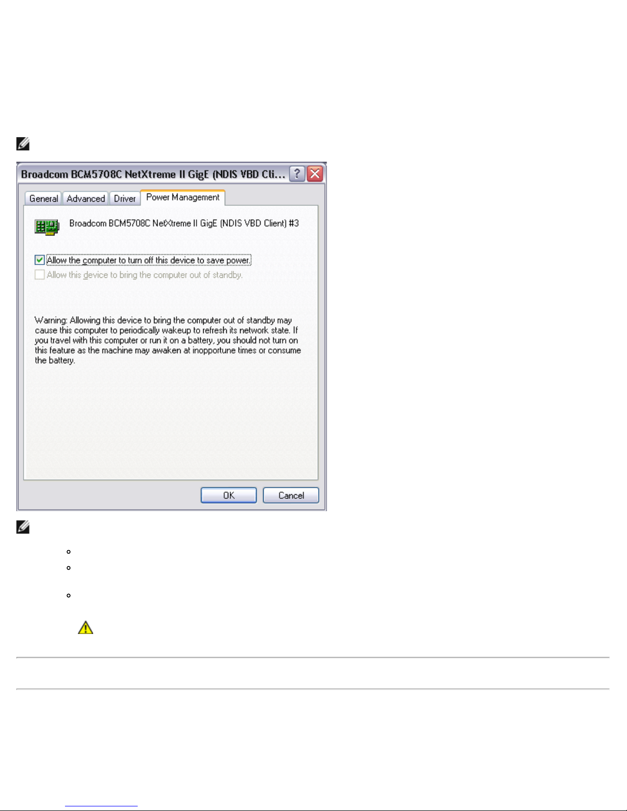
Windows Driver and Application Installation: Broadcom NetXtreme II Network Adapter User Guide
Setting Power Management Options
You can set power management options to allow the operating system to turn off the controller to save power or to allow the
controller to wake up the computer. If the device is busy doing something (servicing a call, for example) however, the
operating system will not shut down the device. The operating system attempts to shut down every possible device only
when the computer attempts to go into hibernation. To have the controller stay on at all times, do not click the Allow the
computer to turn off the device to save power check box.
NOTE: Power management options are not available on blade servers.
NOTES:
The Power Management tab is available only for servers that support power management.
To enable Wake on LAN (WOL) when the computer is on standby, click Allow the device to bring the
computer out of standby box.
If you select Only allow management stations to bring the computer out of standby, the computer can
be brought out of standby only by Magic Packet.
CAUTION! Do not select Allow the computer to turn off the device to save power for any adapter
that is a member of a team.
Please read all Restrictions and Disclaimers.
Back to Contents Page
file:///T|/htdocs/NETWORK/BroadCom/71921/NetXtremeII/en/umwindrv.htm[9/26/2012 3:28:57 PM]
Page 66

iSCSI Protocol: Broadcom NetXtreme II Network Adapter User Guide
Back to Contents Page
iSCSI Protocol: Broadcom NetXtreme II Network Adapter User
Guide
iSCSI Boot
iSCSI Crash Dump
iSCSI Offload
iSCSI Boot
Broadcom NetXtreme II Gigabit Ethernet adapters support iSCSI boot to enable network boot of operating systems to diskless
systems. The iSCSI boot allows a Windows or Linux operating system boot from an iSCSI target machine located remotely
over a standard IP network.
For both Windows and Linux operating systems, iSCSI boot can be configured to boot with two distinctive paths: non-offload
(also known as Microsoft initiator) and offload (Broadcom's offload iSCSI driver or HBA). Configuration of the path is set with
the HBA Boot Mode option located on the General Parameters screen of the iSCSI Configuration utility. See Table 1 for
more information on all General Parameters screen configuration options.
Supported Operating Systems for iSCSI Boot
The Broadcom NetXtreme II Gigabit Ethernet adapters support iSCSI boot on the following operating systems:
Windows Server 2008 32-bit and 64-bit (supports offload and non-offload paths)
Windows Server 2008 R2 64-bit (supports offload and non-offload paths)
Linux RHEL 5.5 and later, SLES 11.1 and later (supports offload and non-offload paths)
SLES 10.x and SLES 11 (only supports non-offload path)
iSCSI Boot Setup
The iSCSI boot setup consists of:
Configuring the iSCSI Target
Configuring iSCSI Boot Parameters
Preparing the iSCSI Boot Image
Booting
Configuring the iSCSI Target
Configuring the iSCSI target varies by target vendors. For information on configuring the iSCSI target, refer to the
documentation provided by the vendor. The general steps include:
1. Create an iSCSI target.
2. Create a virtual disk.
3. Map the virtual disk to the iSCSI target created in step 1.
4. Associate an iSCSI initiator with the iSCSI target.
5. Record the iSCSI target name, TCP port number, iSCSI Logical Unit Number (LUN), initiator Internet Qualified Name
(IQN), and CHAP authentication details.
6. After configuring the iSCSI target, obtain the following:
7. Target IQN
8. Target IP address
9. Target TCP port number
file:///T|/htdocs/NETWORK/BroadCom/71921/NetXtremeII/en/iscsi.htm[9/26/2012 3:29:03 PM]
Page 67

iSCSI Protocol: Broadcom NetXtreme II Network Adapter User Guide
10. Target LUN
11. Initiator IQN
12. CHAP ID and secret
Configuring iSCSI Boot Parameters
Configure the Broadcom iSCSI boot software for either static or dynamic configuration. Refer to Table 1 for configuration
options available from the General Parameters screen.
Table 1 lists parameters for both IPv4 and IPv6. Parameters specific to either IPv4 or IPv6 are noted.
NOTE: Availability of IPv6 iSCSI boot is platform/device dependent.
Table 1: Configuration Options
Option Description
TCP/IP
parameters via
DHCP
IP
Autoconfiguration
iSCSI
parameters via
DHCP
CHAP
Authentication
Boot to iSCSI
target
DHCP Vendor ID
Link Up Delay
Time
Use TCP
Timestamp
Target as First
HDD
LUN Busy Retry
Count
IP Version
HBA Boot Mode
This option is specific to IPv4. Controls whether the iSCSI boot host software acquires the IP address
information using DHCP (Enabled) or use a static IP configuration (Disabled).
This option is specific to IPv6. Controls whether the iSCSI boot host software will configure a stateless
link-local address and/or stateful address if DHCPv6 is present and used (Enabled). Router Solicit packets
are sent out up to three times with 4 second intervals in between each retry. Or use a static IP
configuration (Disabled).
Controls whether the iSCSI boot host software acquires its iSCSI target parameters using DHCP (Enabled)
or through a static configuration (Disabled). The static information is entered through the iSCSI Initiator
Parameters Configuration screen.
Controls whether the iSCSI boot host software uses CHAP authentication when connecting to the iSCSI
target. If CHAP Authentication is enabled, the CHAP ID and CHAP Secret are entered through the iSCSI
Initiator Parameters Configuration screen.
Controls whether the iSCSI boot host software attempts to boot from the iSCSI target after successfully
connecting to it. When the option is enabled, the iSCSI boot host software immediately attempts to boot
form the iSCSI target. If set to disabled, the iSCSI boot host software does not attempt to boot from the
iSCSI target and control returns to the system BIOS so that the next boot device may be used. The One
Time Disabled option is used when you want to do a remote install of the OS to an iSCSI target. As the
option is named, it is set to disable on the first boot, then changes to enabled on subsequent reboots to
indicate that iSCSI boots from the iSCSI target.
Controls how the iSCSI boot host software interprets the Vendor Class ID field used during DHCP. If the
Vendor Class ID field in the DHCP Offer packet matches the value in the field, the iSCSI boot host
software looks into the DHCP Option 43 fields for the required iSCSI boot extensions. If DHCP is disabled,
this value does not need to be set.
Controls how long the iSCSI boot host software waits, in seconds, after an Ethernet link is established
before sending any data over the network. The valid values are 0 to 255. As an example, a user may
need to set a value for this option if a network protocol, such as Spanning Tree, is enabled on the switch
interface to the client system.
Controls if the TCP Timestamp option is enabled or disabled.
Allows specifying that the iSCSI target drive will appear as the first hard drive in the system.
Controls the number of connection retries the iSCSI Boot initiator will attempt if the iSCSI target LUN is
busy.
This option specific to IPv6. Toggles between the IPv4 or IPv6 protocol. All IP settings will be lost when
switching from one protocol version to another.
Set to disable when the host OS is configured for software initiator mode and to enable for HBA mode.
This option is available on NetXtreme II adapters.
MBA Boot Protocol Configuration
To configure the boot protocol
1. Restart your system.
2. From the PXE banner, select CTRL+S. The MBA Configuration Menu appears (see Broadcom Boot Agent).
file:///T|/htdocs/NETWORK/BroadCom/71921/NetXtremeII/en/iscsi.htm[9/26/2012 3:29:03 PM]
Page 68

iSCSI Protocol: Broadcom NetXtreme II Network Adapter User Guide
3. From the MBA Configuration Menu, use the UP ARROW or DOWN ARROW to move to the Boot Protocol option. Use
the LEFT ARROW or RIGHT ARROW to change the Boot Protocol option to iSCSI.
NOTE: For iSCSI boot-capable LOMs, the boot protocol is set via the BIOS. See your system documentation for
more information.
4. Select iSCSI Boot Configuration from Main Menu.
NOTE: If iSCSI boot firmware is not programmed in the NetXtreme II network adapter, selecting iSCSI Boot
Configuration will not have any effect.
iSCSI Boot Configuration
Static iSCSI Boot Configuration
Dynamic iSCSI Boot Configuration
Static iSCSI Boot Configuration
In a static configuration, you must enter data for the system's IP address, the system's initiator IQN, and the target
parameters obtained in Configuring the iSCSI Target. For information on configuration options, see Table 1.
To configure the iSCSI boot parameters using static configuration
1. From the General Parameters Menu screen, set the following:
TCP/IP parameters via DHCP: Disabled. (For IPv4.)
IP Autoconfiguration: Disabled. (For IPv6, non-offload.)
iSCSI parameters via DHCP: Disabled
CHAP Authentication: Disabled
Boot to iSCSI target: Disabled
DHCP Vendor ID: BRCM ISAN
Link Up Delay Time: 0
Use TCP Timestamp: Enabled (for some targets such as the Dell/EMC AX100i, it is necessary to enable Use
TCP Timestamp)
Target as First HDD: Disabled
LUN Busy Retry Count: 0
IP Version: IPv6. (For IPv6, non-offload.)
HBA Boot Mode: Disabled
2. Select ESC to return to the Main menu.
3. From the Main menu, select Initiator Parameters.
4. From the Initiator Parameters screen, type values for the following:
IP Address (unspecified IPv4 and IPv6 addresses should be "0.0.0.0" and "::", respectively)
Subnet Mask Prefix
Default Gateway
Primary DNS
Secondary DNS
iSCSI Name (corresponds to the iSCSI initiator name to be used by the client system)
NOTE: Carefully enter the IP address. There is no error-checking performed against the IP address to check
for duplicates or incorrect segment/network assignment.
5. Select ESC to return to the Main menu.
6. From the Main menu, select 1st Target Parameters.
NOTE: For the initial setup, configuring a second target is not supported.
7. From the 1st Target Parameters screen, enable Connect to connect to the iSCSI target. Type values for the
file:///T|/htdocs/NETWORK/BroadCom/71921/NetXtremeII/en/iscsi.htm[9/26/2012 3:29:03 PM]
Page 69

iSCSI Protocol: Broadcom NetXtreme II Network Adapter User Guide
following using the values used when configuring the iSCSI target:
IP Address
TCP Port
Boot LUN
iSCSI Name
8. Select ESC to return to the Main menu.
9. A second iSCSI boot adapter can be configured for redundancy in the event the primary adapter fails to boot. To
configure the secondary device parameters, select Secondary Device Parameters from the Main menu (see
Configure Parameters for a Secondary Adapter). Otherwise, go to step 10.
10. Select ESC and select Exit and Save Configuration.
11. Select F4 to save your MBA configuration.
Dynamic iSCSI Boot Configuration
In a dynamic configuration, you only need to specify that the system's IP address and target/initiator information are
provided by a DHCP server (see IPv4 and IPv6 configurations in Configuring the DHCP Server to Support iSCSI Boot). For
IPv4, with the exception of the initiator iSCSI name, any settings on the Initiator Parameters, 1st Target Parameters, or 2nd
Target Parameters screens are ignored and do not need to be cleared. For IPv6, with the exception of the CHAP ID and
Secret, any settings on the Initiator Parameters, 1st Target Parameters, or 2nd Target Parameters screens are ignored and do
not need to be cleared. For information on configuration options, see Table 1.
NOTE: When using a DHCP server, the DNS server entries are overwritten by the values provided by the DHCP server.
This occurs even if the locally provided values are valid and the DHCP server provides no DNS server information. When the
DHCP server provides no DNS server information, both the primary and secondary DNS server values are set to 0.0.0.0. When
the Windows OS takes over, the Microsoft iSCSI initiator retrieves the iSCSI Initiator parameters and configures the
appropriate registries statically. It will overwrite whatever is configured. Since the DHCP daemon runs in the Windows
environment as a user process, all TCP/IP parameters have to be statically configured before the stack comes up in the iSCSI
Boot environment.
If DHCP Option 17 is used, the target information is provided by the DHCP server, and the initiator iSCSI name is retrieved
from the value programmed from the Initiator Parameters screen. If no value was selected, then the controller defaults to the
name:
iqn.1995-05.com.broadcom.<11.22.33.44.55.66>.iscsiboot
where the string 11.22.33.44.55.66 corresponds to the controller's MAC address.
If DHCP option 43 (IPv4 only) is used, then any settings on the Initiator Parameters, 1st Target Parameters, or 2nd Target
Parameters screens are ignored and do not need to be cleared.
To configure the iSCSI boot parameters using dynamic configuration
1. From the General Parameters Menu screen, set the following:
TCP/IP parameters via DHCP: Enabled. (For IPv4.)
IP Autoconfiguration: Enabled. (For IPv6, non-offload.)
iSCSI parameters via DHCP: Enabled
CHAP Authentication: Disabled
Boot to iSCSI target: Disabled
DHCP Vendor ID: BRCM ISAN
Link Up Delay Time: 0
Use TCP Timestamp: Enabled (for some targets such as the Dell/EMC AX100i, it is necessary to enable Use
TCP Timestamp)
Target as First HDD: Disabled
LUN Busy Retry Count: 0
IP Version: IPv6. (For IPv6, non-offload.)
HBA Boot Mode: Disabled
2. Select ESC to return to the Main menu.
file:///T|/htdocs/NETWORK/BroadCom/71921/NetXtremeII/en/iscsi.htm[9/26/2012 3:29:03 PM]
Page 70

iSCSI Protocol: Broadcom NetXtreme II Network Adapter User Guide
NOTE: Information on the Initiator Parameters and 1st Target Parameters screens are ignored and do not need
to be cleared.
3. A second iSCSI boot adapter can be configured for redundancy in the event the primary adapter fails to boot. To
configure the secondary device parameters, select Secondary Device Parameters from the Main menu (see
Configure Parameters for a Secondary Adapter). Otherwise, go to step 4.
4. Select Exit and Save Configurations.
Configure Parameters for a Secondary Adapter
A second iSCSI boot adapter can be optionally configured for redundancy in the event the primary adapter fails to boot.
To configure the iSCSI boot parameters for a secondary adapter
1. From the iSCSI Boot Main Menu screen, select Secondary Device Parameters.
2. From the Device List, select the adapter that will be used as the secondary adapter.
3. From the Secondary Device Parameters screen, set the following:
Use Independent Target Portal: Enabled (or Disabled if MPIO mode is not required)
Use Independent Target Name: Enabled
Configure Secondary Device: Invoke
4. Configure the secondary adapter parameters.
NOTE: The IP addresses for the primary and secondary adapters must be in two different subnets.
5. Select ESC and select Exit and Save Configuration.
6. Select F4 to save your MBA configuration.
Enabling CHAP Authentication
Ensure that CHAP authentication is enabled on the target.
To enable CHAP authentication
1. From the General Parameters screen, set CHAP Authentication to Enabled.
2. From the Initiator Parameters screen, type values for the following:
CHAP ID (up to 128 bytes)
CHAP Secret (if authentication is required, and must be 12 characters in length or longer)
3. Select ESC to return to the Main menu.
4. From the Main menu, select 1st Target Parameters.
5. From the 1st Target Parameters screen, type values for the following using the values used when configuring the
iSCSI target:
CHAP ID (optional if two-way CHAP)
CHAP Secret (optional if two-way CHAP, and must be 12 characters in length or longer)
6. Select ESC to return to the Main menu.
7. Select ESC and select Exit and Save Configuration.
Configuring the DHCP Server to Support iSCSI Boot
The DHCP server is an optional component and it is only necessary if you will be doing a dynamic iSCSI Boot configuration
setup (see Dynamic iSCSI Boot Configuration).
Configuring the DHCP server to support iSCSI boot is different for IPv4 and IPv6.
DHCP iSCSI Boot Configurations for IPv4
DHCP iSCSI Boot Configuration for IPv6
DHCP iSCSI Boot Configurations for IPv4
file:///T|/htdocs/NETWORK/BroadCom/71921/NetXtremeII/en/iscsi.htm[9/26/2012 3:29:03 PM]
Page 71

iSCSI Protocol: Broadcom NetXtreme II Network Adapter User Guide
the DHCPv6 client. For iSCSI boot, Broadcom adapters support the following DHCP configurations:
The DHCP protocol includes a number of options that provide configuration information to the DHCP client. For iSCSI boot,
Broadcom adapters support the following DHCP configurations:
DHCP Option 17, Root Path
DHCP Option 43, Vendor-Specific Information
DHCP Option 17, Root Path
Option 17 is used to pass the iSCSI target information to the iSCSI client.
The format of the root path as defined in IETC RFC 4173 is:
"iscsi:"<servername>":"<protocol>":"<port>":"<LUN>":"<targetname>"
The parameters are defined below.
Table 2: DHCP Option 17 Parameter Definition
Parameter Definition
"iscsi:"
<servername>
":"
<protocol>
<port>
A literal string
The IP address or FQDN of the iSCSI target
Separator
The IP protocol used to access the iSCSI target. Currently, only TCP is supported so the protocol is 6.
The port number associated with the protocol. The standard port number for iSCSI is 3260.
The Logical Unit Number to use on the iSCSI target. The value of the LUN must be represented in
<LUN>
hexadecimal format. A LUN with an ID OF 64 would have to be configured as 40 within the option 17
parameter on the DHCP server.
<targetname>
The target name in either IQN or EUI format (refer to RFC 3720 for details on both IQN and EUI formats). An
example IQN name would be "iqn.1995-05.com.broadcom:iscsi-target".
DHCP Option 43, Vendor-Specific Information
DHCP option 43 (vendor-specific information) provides more configuration options to the iSCSI client than DHCP option 17. In
this configuration, three additional suboptions are provided that assign the initiator IQN to the iSCSI boot client along with
two iSCSI target IQNs that can be used for booting. The format for the iSCSI target IQN is the same as that of DHCP
option 17, while the iSCSI initiator IQN is simply the initiator's IQN.
NOTE: DHCP Option 43 is supported on IPv4 only.
The suboptions are listed below.
Table 3: DHCP Option 43 Suboption Definition
Suboption Definition
201
First iSCSI target information in the standard root path format
"iscsi:"<servername>":"<protocol>":"<port>":"<LUN>":"<targetname>"
203 iSCSI initiator IQN
Using DHCP option 43 requires more configuration than DHCP option 17, but it provides a richer environment and provides
more configuration options. Broadcom recommends that customers use DHCP option 43 when performing dynamic iSCSI boot
configuration.
Configuring the DHCP Server
Configure the DHCP server to support option 17 or option 43.
NOTE: If using Option 43, you also need to configure Option 60. The value of Option 60 should match the DHCP Vendor
ID value. The DHCP Vendor ID value is BRCM ISAN, as shown in General Parameters of the iSCSI Boot Configuration
menu.
DHCP iSCSI Boot Configuration for IPv6
The DHCPv6 server can provide a number of options, including stateless or stateful IP configuration, as well s information to
file:///T|/htdocs/NETWORK/BroadCom/71921/NetXtremeII/en/iscsi.htm[9/26/2012 3:29:03 PM]
Page 72

iSCSI Protocol: Broadcom NetXtreme II Network Adapter User Guide
DHCPv6 Option 16, Vendor Class Option
DHCPv6 Option 17, Vendor-Specific Information
NOTE: The DHCPv6 standard Root Path option is not yet available. Broadcom suggests using Option 16 or Option 17
for dynamic iSCSI Boot IPv6 support.
DHCPv6 Option 16, Vendor Class Option
DHCPv6 Option 16 (vendor class option) must be present and must contain a string that matches your configured DHCP
Vendor ID parameter. The DHCP Vendor ID value is BRCM ISAN, as shown in General Parameters of the iSCSI Boot
Configuration menu.
The content of Option 16 should be <2-byte length> <DHCP Vendor ID>.
DHCPv6 Option 17, Vendor-Specific Information
DHCPv6 Option 17 (vendor-specific information) provides more configuration options to the iSCSI client. In this configuration,
three additional suboptions are provided that assign the initiator IQN to the iSCSI boot client along with two iSCSI target
IQNs that can be used for booting.
The suboptions are listed below.
Table 4: DHCP Option 17 Suboption Definition
Suboption Definition
201
203 iSCSI initiator IQN
First iSCSI target information in the standard root path format
"iscsi:"[<servername>]":"<protocol>":"<port>":"<LUN>":"<targetname>"
NOTE: In Table 4, the brackets [ ] are required for the IPv6 addresses.
The content of option 17 should be <2-byte Option Number 201|202|203> <2-byte length> <data>.
Configuring the DHCP Server
Configure the DHCP server to support Option 16 and Option 17.
NOTE:
The format of DHCPv6 Option 16 and Option 17 are fully defined in RFC 3315.
Preparing the iSCSI Boot Image
Windows Server 2008 R2 and SP2 iSCSI Boot Setup
Linux iSCSI Boot Setup
Windows Server 2008 R2 and SP2 iSCSI Boot Setup
The Windows Server 2008 R2 and the Windows Server 2008 SP2 support booting as well as installing in either the offload or
non-offload paths.
The following procedure is to prepare to install and boot the Windows Server 2008 R2 and SP2 iSCSI Boot image in either the
offload or non-offload path. The procedure below references the Windows Server 2008 R2 but procedure is common to both
the Windows Server 2008 R2 and SP2.
CD/iso needed:
Windows 2K8 R2 x64 slipstreamed with KB974072
USB drive:
Place drivers on USB stick: evbd.sys, vbd.sys, ois.sys
Other Software Needed:
file:///T|/htdocs/NETWORK/BroadCom/71921/NetXtremeII/en/iscsi.htm[9/26/2012 3:29:03 PM]
Page 73

iSCSI Protocol: Broadcom NetXtreme II Network Adapter User Guide
Bindview.exe (see KB976042)
Procedure:
1. Remove any local hard drives on the SUT.
2. Load the latest Broadcom MBA and iSCSI boot images onto NVRAM of the AUT.
3. Configure SUT's BIOS to have the Broadcom MBA as the first bootable device, and the CDROM as the second device.
4. Configure the iSCSI Target, with sufficient disk space to hold new O/S installation, to allow connection from the SUT.
5. Boot up system. At PXE banner, press Ctrl+S to enter PXE menu.
6. At PXE menu, set Boot Protocol to iSCSI.
7. Enter iSCSI target parameters.
8. Set HBA Boot Mode to Enabled or Disabled.
9. In General Parameters, set Boot to Target parameter to One-Time Disabled.
10. Save settings, and reboot system.
11. SUT should connect to target, and then boot to DVDROM device.
12. Boot to DVD and begin installation.
13. Answer all the installation questions with appropriate answers. (such as Operating System you want to install, accept
the license terms, etc.).
14. When the Where you want to install Windows? dialog window appears, select Load Drivers. Plug in USB device,
which contains drivers, into SUT.
a. If HBA Boot Mode is Enabled: load evbd/vbd and ois drivers.
b. IF HBA Boot Mode is Disabled: load evbd/vbd and ndis drivers.
15. Target Drive should be seen. This is a drive connected via the iSCSI boot protocol, located in the remote iSCSI target)
Select Next to proceed W2K8R2 installation.
16. A few minutes after the W2K8R2 DVD installation process starts, there will be a system restart follows.
17. After a reboot, W2K8R2 installation routine should start and continue on. (Completing installation).
18. Then there will be another system restart follows, check and verify the SUT is able to boot to the desktop.
19. After W2K8R2 is booted up, load all drivers and run Bindview.exe.
a. Select: All Services.
b. Under WFP Lightweight Filter you should see Binding paths for the AUT. Right click and disable them. When
done close out.
20. Verify the OS and system is functional, and able to pass traffic by pinging a remote system's IP, etc.
21. Test and verify iSCSI boot remains functional over both NDIS and OIS path in both IPv4 and all IPv6 protocols.
Linux iSCSI Boot Setup
Linux iSCSI boot is supported on Red Hat Enterprise Linux 5.5 and later and SUSE Linux Enterprise Server 11 PS1 and later in
both the offload and non-offload paths. SLES 10.x and SLES 11 support only the non-offload path.
There are two methods to set up Linux iSCSI boot:
Local hard drive installation
Remote DVD installation
Local hard drive installation
1. Install Linux OS on your local hard drive and make sure open-iscsi initiator is up to date.
2. Make sure all Runlevels of network service are on.
3. Make sure 2, 3, and 5 Runlevels of iscsi service are on.
4. Update uIP. You can get uIP package from Broadcom CD. This step is not needed for SuSE 10.
5. Install linux-nx2 package on you linux system. You can get this package from Broadcom CD.
6. Install bibt package on you Linux system. You can get this package from Broadcom CD.
7. Delete all ifcfg-eth* files.
file:///T|/htdocs/NETWORK/BroadCom/71921/NetXtremeII/en/iscsi.htm[9/26/2012 3:29:03 PM]
Page 74

iSCSI Protocol: Broadcom NetXtreme II Network Adapter User Guide
8. Configure one port of network adapter to connect to iSCSI Target (see how to setup iSCSI target in corresponding
section).
9. Connect to iSCSI Target.
10. Use DD command to copy local hard drive to iSCSI Target.
11. When DD is done, execute sync command a couple of times, logout then login to iSCSI Target again.
12. Run fsck command on all partitions created on iSCSI Target.
13. Change to /OPT/bcm/bibt folder and run the iscsi_setup.sh script to create the initrd images. Option 0 will create nonoffload image and option 1 will create offload image. Iscsi_script.sh script will create the non-offload image only on
SuSE 10 as offload is not supported on SuSE 10.
14. Mount the /boot partition on the iSCSI Target.
15. Copy the initrd images you created in step 13 from your local hard drive to the partition mounted in step 14.
16. On the partition mounted in step 14, edit grub menu to point to the new initrd images.
17. Unmount the /boot partition on the iSCSI Target.
18. (Red hat Only) To enable CHAP, you need to modify the CHAP section of the iscsid.conf file on the iSCSI Target. Edit
iscsid.conf file with one or two way CHAP information as desired.
19. Shut down system and disconnect local hard drive. Now you are ready to iSCSI boot into iSCSI Target.
20. Configure iSCSI Boot Parameters including CHAP parameters if desired (see corresponding sections).
21. Continue booting into iSCSI Boot image and choose one of the images you created (non-offload or offload). Your choice
should correspond with your choice in the iSCSI Boot parameters section. If HBA Boot Mode was enabled in the iSCSI
Boot Parameters section, you have to boot the offload image. SuSE 10.x and SLES 11 do not support offload.
Remote DVD installation
Installation using the remote DVD method can only be performed through the non-offload path. After completing the
installation, the system can be setup to boot from either the non-offload or offload paths as described in the procedure below.
Starting with Red Hat 6.2 and SLES 11.2, installing through the offload path will be supported.
1. Get the latest Broadcom Linux driver CD.
2. Configure iSCSI Boot Parameters for DVD direct install to target by disabling Boot from target option on network
adapter.
3. To set to the non-offload path, set HBA Boot Mode to Disabled in the NVRAM Configuration.
4. Change boot order as follows:
a. Boot from the network adapter.
b. Boot from the CD/DVD driver.
5. Reboot the system.
6. System will connect to iSCSI target, then will boot from CD/DVD drive.
7. Follow the corresponding OS instructions.
a. Red Hat 5.5 - Type "linux dd" at "boot:" prompt and press enter
b. Red Hat 6.0
c. SuSE 10
d. SuSE 11.1 choose "installation" and type withiscsi=1 netsetup=1 at boot option and choose YES for F6 driver
option.
8. Follow the instructions to load the driver CD.
9. At the "networking device" prompt, choose the desired network adapter port and press OK.
10. At "configure TCP/IP prompt configure the way the system acquire IP address and press OK.
11. If static IP was chosen, you need to enter IP information for iscsi initiator.
12. (Red hat) choose to "skip" media testing.
13. Continue installation as desired. A drive will be available at this point. After file copying is done, remove CD/DVD and
reboot system.
14. When system reboot, enable "boot from target" in iSCSI Boot Parameters and continue with installation until it is done.
15. Update iscsi initiator if needed. You need to remove existing one first.
file:///T|/htdocs/NETWORK/BroadCom/71921/NetXtremeII/en/iscsi.htm[9/26/2012 3:29:03 PM]
Page 75

iSCSI Protocol: Broadcom NetXtreme II Network Adapter User Guide
16. Make sure all runlevels of network service are on.
rc_reset
17. Make sure 2,3 and 5 runlevels of iscsi service are on.
18. For Red Hat 6.0, make sure Network Manager service is stopped and disabled.
19. Install uIP (not required for SuSE 10).
20. Install linux-nx2 package.
21. Install bibt package.
22. Remove ifcfg-eth*.
23. Reboot.
24. For SUSE 11.1, follow remote DVD installation workaround.
25. After system reboot, login and change to /opt/bcm/bibt folder and run iscsi_setup.sh script to create offload and nonoffload initrd images.
26. Copy the initrd images, offload and non-offload, to the /boot folder.
27. Change the grub menu to point to the new initrd images.
28. To enable CHAP you need to modify iscsid.conf (Red Hat only).
29. Reboot and change CHAP parameters if desired.
30. Continue booting into the iSCSI Boot image and select one of the images you created (non-offload or offload). Your
choice should correspond with your choice in the iSCSI Boot parameters section. If HBA Boot Mode was enabled in the
iSCSI Boot Parameters section, you have to boot the offload image. SLES 10.x and SLES 11 do not support offload.
SUSE 11.1 Remote DVD installation workaround
1. Create a new file called boot.open-iscsi with the content shown below.
2. Copy the file you just created to /etc/init.d/ folder and overwrite the existing one.
Content of the new boot.open-iscsi file:
#!/bin/bash
#
# /etc/init.d/iscsi
#
### BEGIN INIT INFO
# Provides: iscsiboot
# Required-Start:
# Should-Start: boot.multipath
# Required-Stop:
# Should-Stop: $null
# Default-Start: B
# Default-Stop:
# Short-Description: iSCSI initiator daemon root-fs support
# Description: Starts the iSCSI initiator daemon if the
# root-filesystem is on an iSCSI device
#
### END INIT INFO
ISCSIADM=/sbin/iscsiadm
ISCSIUIO=/sbin/iscsiuio
CONFIG_FILE=/etc/iscsid.conf
DAEMON=/sbin/iscsid
ARGS="-c $CONFIG_FILE"
# Source LSB init functions
. /etc/rc.status
#
# This service is run right after booting. So all targets activated
# during mkinitrd run should not be removed when the open-iscsi
# service is stopped.
#
iscsi_load_iscsiuio()
{
TRANSPORT=`$ISCSIADM -m session 2> /dev/null | grep "bnx2i"`
if [ "$TRANSPORT" ] ; then
echo -n "Launch iscsiuio "
startproc $ISCSIUIO
fi
}
iscsi_mark_root_nodes()
{
$ISCSIADM -m session 2> /dev/null | while read t num i target ; do
ip=${i%%:*}
STARTUP=`$ISCSIADM -m node -p $ip -T $target 2> /dev/null | grep "node.conn\[0\].startup" | cut d' ' -f3`
if [ "$STARTUP" -a "$STARTUP" != "onboot" ] ; then
$ISCSIADM -m node -p $ip -T $target -o update -n node.conn[0].startup -v onboot
fi
done
}
# Reset status of this service
file:///T|/htdocs/NETWORK/BroadCom/71921/NetXtremeII/en/iscsi.htm[9/26/2012 3:29:03 PM]
Page 76

iSCSI Protocol: Broadcom NetXtreme II Network Adapter User Guide
# We only need to start this for root on iSCSI
if ! grep -q iscsi_tcp /proc/modules ; then
if ! grep -q bnx2i /proc/modules ; then
rc_failed 6
rc_exit
fi
fi
case "$1" in
start)
echo -n "Starting iSCSI initiator for the root device: "
iscsi_load_iscsiuio
startproc $DAEMON $ARGS
rc_status -v
iscsi_mark_root_nodes
;;
stop|restart|reload)
rc_failed 0
;;
status)
echo -n "Checking for iSCSI initiator service: "
if checkproc $DAEMON ; then
rc_status -v
else
rc_failed 3
rc_status -v
fi
;;
*)
echo "Usage: $0 {start|stop|status|restart|reload}"
exit 1
;;
esac
rc_exit
Booting
After that the system has been prepared for an iSCSI boot and the operating system is present on the iSCSI target, the last
step is to perform the actual boot. The system will boot to Windows or Linux over the network and operate as if it were a
local disk drive.
1. Reboot the server.
2. Select CTRL+S.
3. From the Main menu, select General Parameters and configure the Boot to iSCSI target option to Enabled.
4. To boot through an offload path, set the HBA Boot Mode to Enabled. To boot through a non-offload path, set the HBA
Boot Mode to Disabled.
If CHAP authentication is needed, enable CHAP authentication after determining that booting is successful (see Enabling CHAP
Authentication).
Other iSCSI Boot Considerations
There are several other factors that should be considered when configuring a system for iSCSI boot.
Locally Administered Address
A user-defined MAC address assigned through the Locally Administered Address property of the Advanced section of the BACS
Configurations tab is not supported on iSCSI boot-enabled devices.
Virtual LANs
Virtual LAN (VLAN) tagging is not supported for iSCSI boot with the Microsoft iSCSI Software Initiator.
Troubleshooting iSCSI Boot
The following troubleshooting tips are useful for iSCSI boot.
Problem: When switching iSCSI boot from the Microsoft standard path to Broadcom iSCSI offload, the booting fails to
complete.
Solution: Install or upgrade the Broadcom Virtual Bus Device (VBD) driver to 5.0.x, along with the OIS driver, prior to
switching the iSCSI boot path.
Problem: The iSCSI configuration utility will not run.
Solution: Ensure that the iSCSI Boot firmware is installed in the NVRAM.
file:///T|/htdocs/NETWORK/BroadCom/71921/NetXtremeII/en/iscsi.htm[9/26/2012 3:29:03 PM]
Page 77

iSCSI Protocol: Broadcom NetXtreme II Network Adapter User Guide
Problem: A system blue screen occurs when installing the Broadcom drivers through Windows Plug-and-Play (PnP).
Solution: Install the drivers through the Setup installer.
Problem: For static IP configuration when switching from Layer 2 iSCSI boot to Broadcom iSCSI HBA, then you will receive
an IP address conflict.
Solution: Change the IP address of the network property in the OS.
Problem: After configuring the iSCSI boot LUN to 255, a system blue screen appears when performing iSCSI boot.
Solution: Although Broadcom's iSCSI solution supports a LUN range from 0 to 255, the Microsoft iSCSI software initiator
does not support a LUN of 255. Configure a LUN value from 0 to 254.
Problem: The Xen hypervisor will not start when booting from an iSCSI image created with the RHEL 5.4 Xen kernel.
Solution: This is a known third-party issue. To work around this issue, disable the Xen hypervisor's EDD feature by editing
the grub.conf file in the boot/grub folder to add the edd=off switch to the end of the kernel line. For example,
kernel /xen.gz edd=off.
Problem: Unable to connect to an EqualLogic target using Windows Server 2008 and higher.
Solution: Add an exception to your firewall to allow ICMP echo requests.
Problem: The iSCSI target is not present as a disk when installing Windows Server 2008 R2 with a NetXtreme II 1G or 10G
adapter.
Solution: See the resolution below.
First, install the Windows Automated Installation Kit (AIK) from Microsoft on the test machine where you are going to modify
the OS media. Then delete the old network drivers in the boot.wim of the OS media by following the procedure below.
1. Create a temporary folder, such as D:\temp.
2. Create the following two subfolders in the temporary folder:
Win2008R2Copy
Win2008R2Mod
3. Copy all the contents from the DVD installation media into the Win2008R2Copy folder.
4. Open the Windows AIK command prompt in elevated mode from All program, and then run the following command:
attrib –r D:\Temp\Win2008R2Copy\sources\boot.wim
5. Run the following command to mount the boot.wim image:
dism /Mount-WIM /WimFile:D:\Temp\Win2008R2Copy\sources\boot.wim /index:1
/MountDir:D:\Temp\Win2008R2Mod
6. The Boot.wim image was mounted in the Win2008R2Mod folder. Find all the instances of the files listed below in the
subfolders of the Win2008R2Mod folder, and then delete them.
List of files to be deleted.
netevbda.inf
netevbda.pnf
evbda.sys
netbxnda.inf
netbxnda.pnf
bxnd60a.sys
bxvbda.sys
netbvbda.inf
netbvbda.pnf
To easily find all the instances of the files to be deleted, run the following command:
dir /s D:\Temp\Win2008R2Mod\filename
7. Run the following command to unmount the Boot.wim image:
dism /unmount-wim /Mountdir:D:\Temp\Win2008R2Mod /commit
8. Repeat steps 5 to 7 by keeping the index = 2 for the command in step 5.
9. Run the following command to create an .iso file:
oscdimg -e -h -m -n -lWS08R2_x64 -bootdata:2#p0,e,b"c:\Program Files\Windows
AIK\Tools\PETools\amd64\boot\etfsboot.com"#pEF,e,b"c:\Program Files\Windows
AIK\Tools\PETools\amd64\boot\efisys.bin" D:\Temp\Win2008R2Copy D:\Temp\Win2008R2Mod.iso
file:///T|/htdocs/NETWORK/BroadCom/71921/NetXtremeII/en/iscsi.htm[9/26/2012 3:29:03 PM]
Page 78

iSCSI Protocol: Broadcom NetXtreme II Network Adapter User Guide
Note: The above command is a single continuous command.
1. Burn the Win2008R2Mod.iso file to a DVD.
2. Perform the installation by using the new DVD and provide the network controller drivers during installation. You will
receive the iSCSI LUN to complete the installation.
iSCSI Crash Dump
If you will use the Broadcom iSCSI Crash Dump utility, it is important to follow the installation procedure to install the iSCSI
Crash Dump driver. See Using the Installer for more information.
iSCSI Offload
iSCSI offload is a technology that offloads iSCSI protocol processing overhead from host processors to the iSCSI host bus
adapter to increase network performance and throughput while helping to optimize server processor utilization.
This section covers Broadcom's iSCSI offload feature for the NetXtreme II family of network adapters. For Linux iSCSI offload,
see Linux iSCSI Offload.
iSCSI Offload Limitations
The bnx2i driver for iSCSI does not operate on a stand-alone PCI device. It shares the same PCI device with the networking
driver (bnx2 and bnx2x). The networking driver alone supports layer 2 networking traffic. Offloaded iSCSI operations require
both the networking driver and the bnx2i driver.
iSCSI operations will be interrupted when the networking driver brings down or resets the device. This scenario requires
proper handling by the networking and bnx2i drivers, as well as the userspace iscsid daemon that keeps track of all iSCSI
sessions. Offloaded iSCSI connections take up system and on-chip resources that must be freed up before the device can be
reset. iscsid running in userspace is generally less predictable, as it can run slowly and take a long time to disconnect and
reconnect iSCSI sessions during network reset, especially when the number of connections is large. Broadcom cannot
guarantee that iSCSI sessions will always recover in every conceivable scenario when the networking device is repeatedly
being reset. Broadcom recommends that administrator-administered network device resets, such as MTU change, ring size
change, device shutdown, hot-unplug, and so forth, be kept at a minimum while there are active offloaded iSCSI sessions
running on that shared device. On the other hand, link-related changes do not require device reset and are safe to be
performed at any time.
To help alleviate some of the above issues, install the latest open-iscsi utilities by upgrading your Red Hat Network
subscription.
Configuring iSCSI Offload
With the proper iSCSI offload licensing, you can configure your iSCSI-capable NetXtreme II network adapter to offload iSCSI
processing from the host processor. The following process enables your system to take advantage of Broadcom's iSCSI
offload feature.
Installing Broadcom Drivers and Management Applications
Installing the Microsoft iSCSI Initiator
Configuring Broadcom iSCSI Using BACS
Configure Microsoft Initiator to Use Broadcom's iSCSI Offload
Installing Broadcom Drivers and Management Applications
Install the Windows drivers and management applications. See Installing Windows Drivers and Management Applications.
Installing the Microsoft iSCSI Initiator
For Windows Server 2008 and later, the iSCSI initiator is included inbox. To download the iSCSI initiator from Microsoft, go to
http://www.microsoft.com/download/en/details.aspx?displaylang=en&id=18986 and locate the direct link for your system.
Configuring Broadcom iSCSI Using BACS
file:///T|/htdocs/NETWORK/BroadCom/71921/NetXtremeII/en/iscsi.htm[9/26/2012 3:29:03 PM]
Page 79
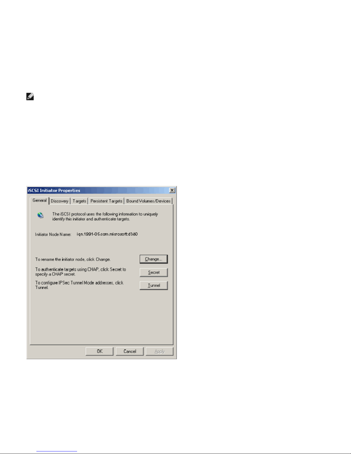
iSCSI Protocol: Broadcom NetXtreme II Network Adapter User Guide
The Broadcom Advanced Control Suite (BACS) is used to manage all of Broadcom's network adapters and advanced features.
For more information, see Using Broadcom Advanced Control Suite 4.
1. Open BACS.
2. Select the Broadcom NetXtreme II C-NIC iSCSI adapter. If the C-NIC iSCSI adapter is not present, then select the VBD
device and enable iSCSI offload by selecting iSCSI Offload Engine from the Resource Reservations area of the
Configuration tab. See Viewing and Configuring Resource Reservations.
3. Select the Configuration tab.
4. DHCP is the default for IP address assignment, but this can be changed to static IP address assignment, if this is the
preferred method of IP address assignment.
NOTE: The IP address assignment method cannot be changed if the adapter was used for boot.
5. Select Apply and close BACS.
Configure Microsoft Initiator to Use Broadcom's iSCSI Offload
Now that the IP address has been configured for the iSCSI adapter, you need to use Microsoft Initiator to configure and add a
connection to the iSCSI target using Broadcom iSCSI adapter. See Microsoft's user guide for more details on Microsoft
Initiator.
1. Open Microsoft Initiator.
2. Configure the initiator IQN name according to your setup. To change, click on Change.
3. Enter the initiator IQN name.
file:///T|/htdocs/NETWORK/BroadCom/71921/NetXtremeII/en/iscsi.htm[9/26/2012 3:29:03 PM]
Page 80
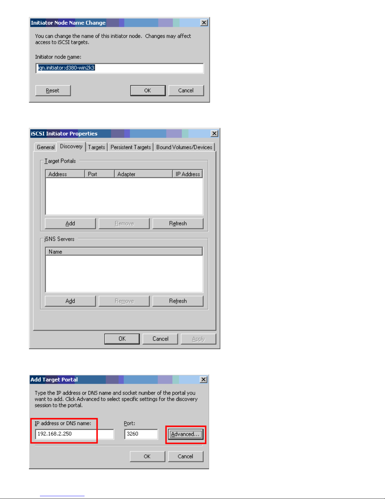
iSCSI Protocol: Broadcom NetXtreme II Network Adapter User Guide
4. Select the Discovery tab and click Add to add a target portal.
5. Enter the IP address of the target and click Advanced.
file:///T|/htdocs/NETWORK/BroadCom/71921/NetXtremeII/en/iscsi.htm[9/26/2012 3:29:03 PM]
Page 81
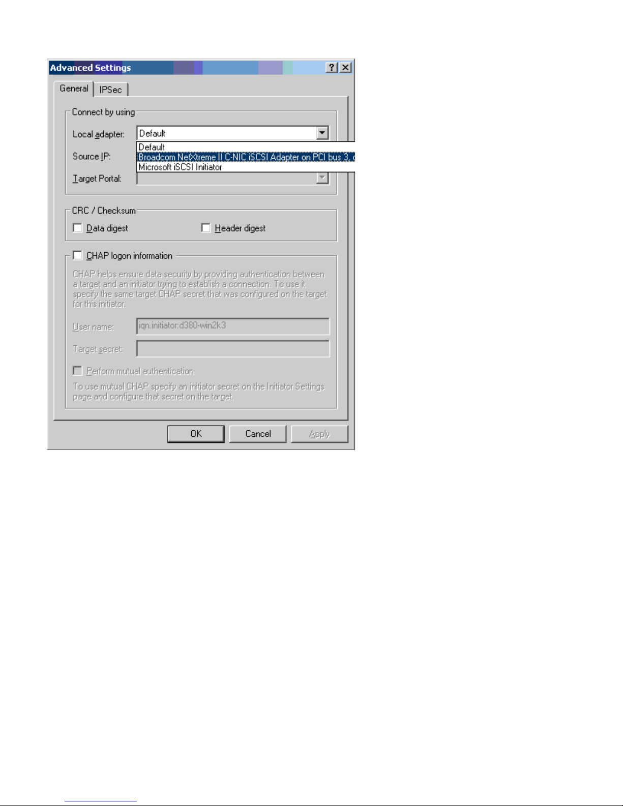
iSCSI Protocol: Broadcom NetXtreme II Network Adapter User Guide
6. From the General tab, select Broadcom NetXtreme II C-NIC iSCSI Adapter from Local adapter.
7. Select the IP address for the adapter from Source IP.
file:///T|/htdocs/NETWORK/BroadCom/71921/NetXtremeII/en/iscsi.htm[9/26/2012 3:29:03 PM]
Page 82
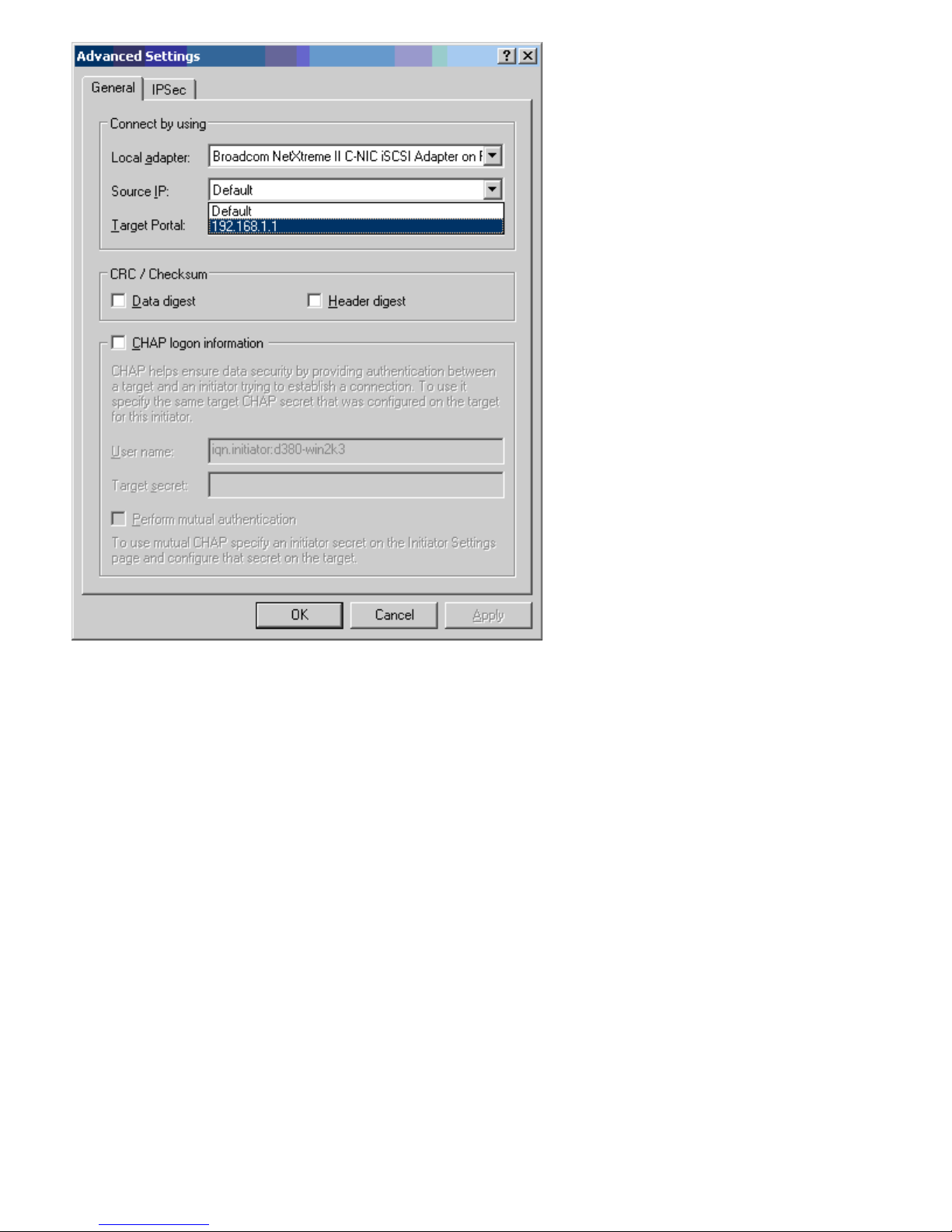
iSCSI Protocol: Broadcom NetXtreme II Network Adapter User Guide
8. Click OK to close Advanced setting and then OK to add the target portal.
file:///T|/htdocs/NETWORK/BroadCom/71921/NetXtremeII/en/iscsi.htm[9/26/2012 3:29:03 PM]
Page 83
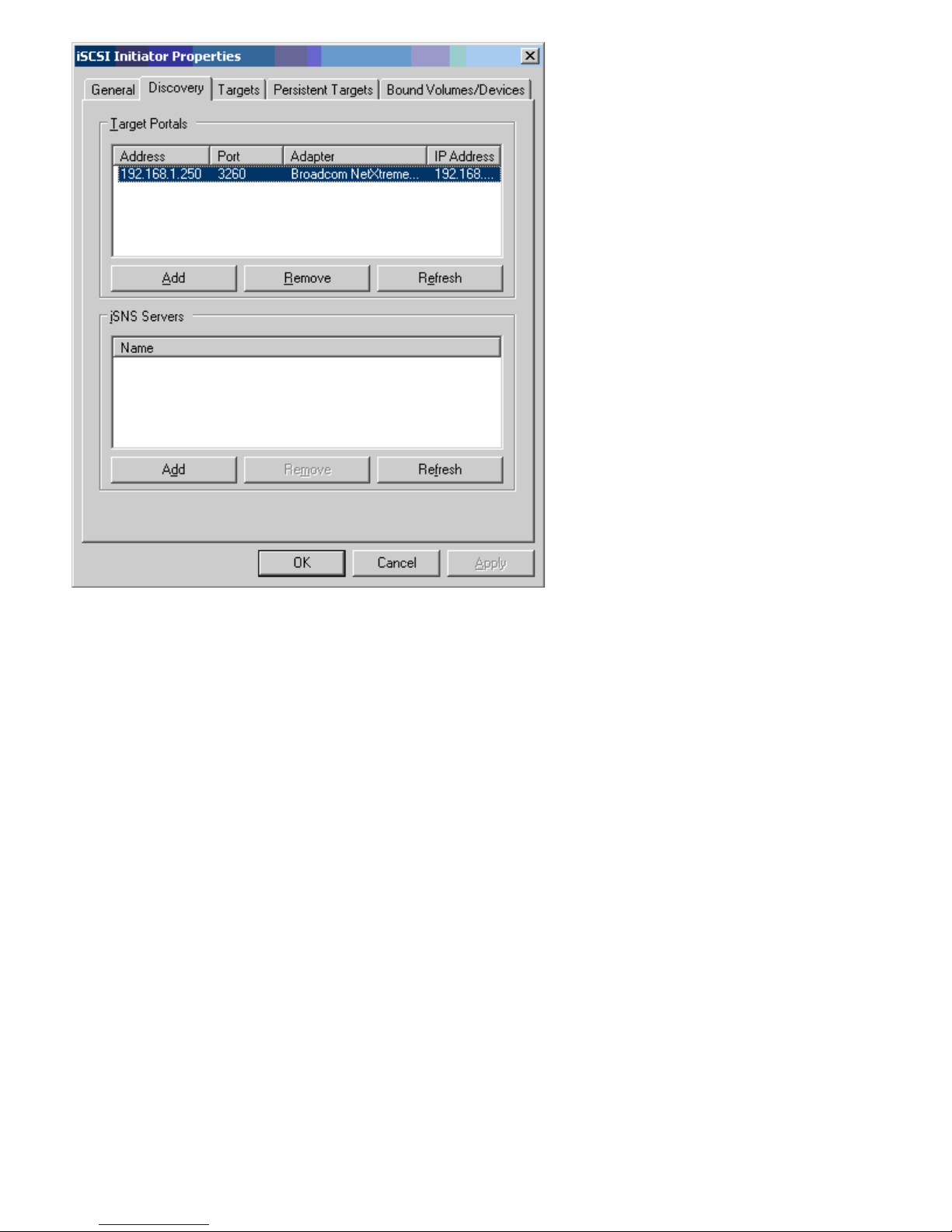
iSCSI Protocol: Broadcom NetXtreme II Network Adapter User Guide
9. From the Targets tab, select the target and click Log On to log into your iSCSI target using the Broadcom iSCSI
adapter.
file:///T|/htdocs/NETWORK/BroadCom/71921/NetXtremeII/en/iscsi.htm[9/26/2012 3:29:03 PM]
Page 84
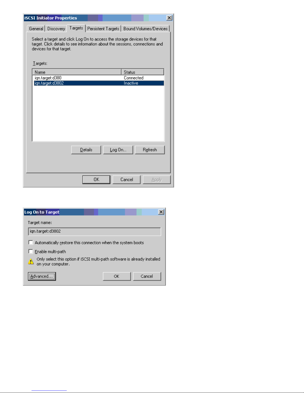
iSCSI Protocol: Broadcom NetXtreme II Network Adapter User Guide
10. Click on Advanced.
11. On the General tab, select the Broadcom NetXtreme Ii C-NIC iSCSI adapter from Local adapter.
12. Click OK to close Advanced settings.
file:///T|/htdocs/NETWORK/BroadCom/71921/NetXtremeII/en/iscsi.htm[9/26/2012 3:29:03 PM]
Page 85
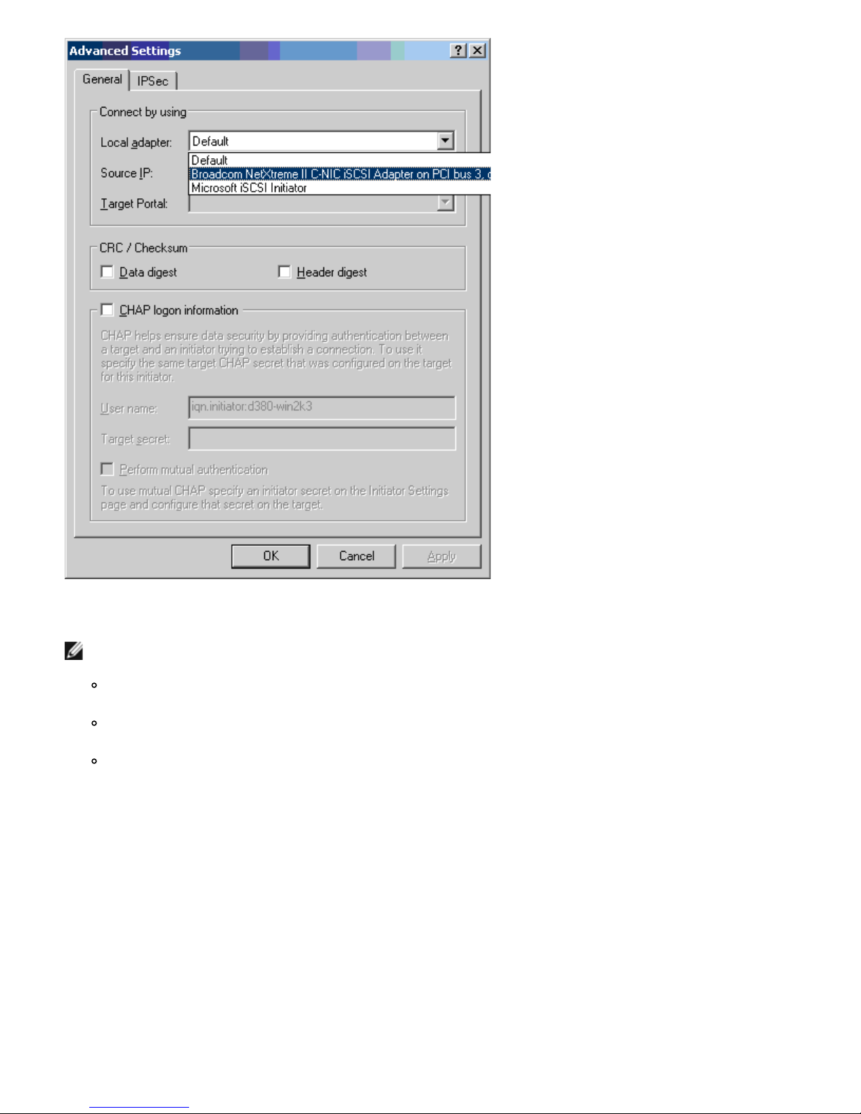
iSCSI Protocol: Broadcom NetXtreme II Network Adapter User Guide
13. Click OK to close the Microsoft Initiator.
14. To format your iSCSI partition, use Disk Manager.
NOTES:
No teaming support for iSCSI-enabled adapters is available at this point. MPIO handles all failover and link
aggregation for iSCSI traffic.
Network teaming and MPIO are supported concurrently on different ports. Ports running iSCSI use MPIO and
ports running LAN traffic use network teaming.
If a Broadcom network adapter has iSCSI offload enabled, the teaming software, BASP, will not allow the iSCSI
offload enabled network port interface to be a part of a GEC or LACP (802.3ad) team, but SLB teams are
allowed.
iSCSI Offload FAQs
Q: How do I assign an IP address for iSCSI offload?
A: Use the Configurations tab in Broadcom Advanced Control Suite (BACS).
Q: What tools should be used to create the connection to the target?
A: Use Microsoft iSCSI Software Initiator (version 2.08 or later).
Q: How do I know that the connection is offloaded?
A: Use Microsoft iSCSI Software Initiator. From a command line, type iscsicli sessionlist. From Initiator Name, an
iSCSI offloaded connection will display an entry beginning with "B06BDRV...". A non-offloaded connection will display an entry
beginning with "Root...".
Q: What configurations should be avoided?
A: The IP address should not be the same as the LAN.
file:///T|/htdocs/NETWORK/BroadCom/71921/NetXtremeII/en/iscsi.htm[9/26/2012 3:29:03 PM]
Page 86

iSCSI Protocol: Broadcom NetXtreme II Network Adapter User Guide
Q: Why does the install fail when attempting to complete an iSCSI offload install using Windows Server 2008 R2 for BCM5709
(1 GbE) adapters?
A: There is a conflict with the internal inbox driver.
Event Log Messages
Table 5 lists the offload iSCSI driver event log messages.
Offload iSCSI (OIS) Driver
Table 5: Offload iSCSI (OIS) Driver Event Log Messages
Message
Number
1 Error
2 Error The initiator could not allocate resources for an iSCSI session.
3 Error
4 Error
5 Error Failed to setup initiator portal. Error status is given in the dump data.
6 Error The initiator could not allocate resources for an iSCSI connection
7 Error The initiator could not send an iSCSI PDU. Error status is given in the dump data.
8 Error
9 Error Target did not respond in time for a SCSI request. The CDB is given in the dump data.
10 Error Login request failed. The login response packet is given in the dump data.
11 Error
12 Error Target provided invalid data for login redirect. Dump data contains the data returned by the target.
13 Error Target offered an unknown AuthMethod. Dump data contains the data returned by the target.
14 Error
15 Error
16 Error An invalid key was received during CHAP negotiation. The key=value pair is given in the dump data.
17 Error
18 Error Header Digest is required by the initiator, but target did not offer it.
19 Error Data Digest is required by the initiator, but target did not offer it.
20 Error Connection to the target was lost. The initiator will attempt to retry the connection.
21 Error
22 Error Header digest error was detected for the given PDU. Dump data contains the header and digest.
23 Error Target sent an invalid iSCSI PDU. Dump data contains the entire iSCSI header.
24 Error Target sent an iSCSI PDU with an invalid opcode. Dump data contains the entire iSCSI header.
25 Error
26 Error Target trying to send more data than requested by the initiator.
27 Error
28 Error Initiator received an invalid R2T packet. Dump data contains the entire iSCSI header.
Severity Message
Initiator failed to connect to the target. Target IP address and TCP Port number are given in dump
data.
Maximum command sequence number is not serially greater than expected command sequence
number in login response. Dump data contains Expected Command Sequence number followed by
Maximum Command Sequence number.
MaxBurstLength is not serially greater than FirstBurstLength. Dump data contains FirstBurstLength
followed by MaxBurstLength.
Target or discovery service did not respond in time for an iSCSI request sent by the initiator. iSCSI
Function code is given in the dump data. For details about iSCSI Function code please refer to iSCSI
User's Guide.
Target returned an invalid login response packet. The login response packet is given in the dump
data.
Target offered an unknown digest algorithm for CHAP. Dump data contains the data returned by the
target.
CHAP challenge given by the target contains invalid characters. Dump data contains the challenge
given.
CHAP Response given by the target did not match the expected one. Dump data contains the CHAP
response.
Data Segment Length given in the header exceeds MaxRecvDataSegmentLength declared by the
target.
Data digest error was detected. Dump data contains the calculated checksum followed by the given
checksum.
Initiator could not find a match for the initiator task tag in the received PDU. Dump data contains the
entire iSCSI header.
file:///T|/htdocs/NETWORK/BroadCom/71921/NetXtremeII/en/iscsi.htm[9/26/2012 3:29:03 PM]
Page 87

iSCSI Protocol: Broadcom NetXtreme II Network Adapter User Guide
29 Error Target rejected an iSCSI PDU sent by the initiator. Dump data contains the rejected PDU.
30 Error Initiator could not allocate a work item for processing a request.
31 Error Initiator could not allocate resource for processing a request.
32 Information Initiator received an asynchronous logout message. The Target name is given in the dump data.
33 Error Challenge size given by the target exceeds the maximum specified in iSCSI specification.
34 Information
A connection to the target was lost, but Initiator successfully reconnected to the target. Dump data
contains the target name.
35 Error Target CHAP secret is smaller than the minimum size (12 bytes) required by the specification.
36 Error
Initiator CHAP secret is smaller than the minimum size (12 bytes) required by the specification.
Dump data contains the given CHAP secret.
37 Error FIPS service could not be initialized. Persistent logons will not be processed.
38 Error Initiator requires CHAP for logon authentication, but target did not offer CHAP.
39 Error
Initiator sent a task management command to reset the target. The target name is given in the
dump data.
40 Error Target requires logon authentication via CHAP, but Initiator is not configured to perform CHAP.
41 Error Target did not send AuthMethod key during security negotiation phase.
42 Error
Target sent an invalid status sequence number for a connection. Dump data contains Expected Status
Sequence number followed by the given status sequence number.
43 Error Target failed to respond in time for a login request.
44 Error Target failed to respond in time for a logout request.
45 Error
Target failed to respond in time for a login request. This login request was for adding a new
connection to a session.
46 Error Target failed to respond in time for a SendTargets command.
47 Error Target failed to respond in time for a SCSI command sent through a WMI request.
48 Error Target failed to respond in time to a NOP request.
49 Error Target failed to respond in time to a Task Management request.
50 Error Target failed to respond in time to a Text Command sent to renegotiate iSCSI parameters.
51 Error
52 Error
53 Error
Target failed to respond in time to a logout request sent in response to an asynchronous message
from the target.
Initiator Service failed to respond in time to a request to configure IPSec resources for an iSCSI
connection.
Initiator Service failed to respond in time to a request to release IPSec resources allocated for an
iSCSI connection.
54 Error Initiator Service failed to respond in time to a request to encrypt or decrypt data.
55 Error Initiator failed to allocate resources to send data to target.
56 Error Initiator could not map an user virtual address to kernel virtual address resulting in I/O failure.
57 Error Initiator could not allocate required resources for processing a request resulting in I/O failure.
58 Error Initiator could not allocate a tag for processing a request resulting in I/O failure.
59 Error Target dropped the connection before the initiator could transition to Full Feature Phase.
60 Error
Target sent data in SCSI Response PDU instead of Data_IN PDU. Only Sense Data can be sent in
SCSI Response.
61 Error Target set DataPduInOrder to NO when initiator requested YES. Login will be failed.
62 Error Target set DataSequenceInOrder to NO when initiator requested YES. Login will be failed.
63 Error Cannot reset the target or LUN. Will attempt session recovery.
64 Information Attempt to bootstrap Windows using iSCSI NIC Boot (iBF).
65 Error Booting from iSCSI, but could not set any NIC in Paging Path.
66 Error Attempt to disable the Nagle Algorithm for iSCSI connection failed.
67 Information If Digest support selected for iSCSI Session, will use Processor support for Digest computation.
68 Error
After receiving an async logout from the target, attempt to relogin the session failed. Error status is
given in the dump data.
69 Error Attempt to recover an unexpected terminated session failed. Error status is given in the dump data.
file:///T|/htdocs/NETWORK/BroadCom/71921/NetXtremeII/en/iscsi.htm[9/26/2012 3:29:03 PM]
Page 88

iSCSI Protocol: Broadcom NetXtreme II Network Adapter User Guide
Error occurred when processing iSCSI logon request. The request was not retried. Error status is
70 Error
71 Information
given in the dump data.
Initiator did not start a session recovery upon receiving the request. Dump data contains the error
status.
72 Error Unexpected target portal IP types. Dump data contains the expected IP type.
Please read all Restrictions and Disclaimers.
Back to Contents Page
file:///T|/htdocs/NETWORK/BroadCom/71921/NetXtremeII/en/iscsi.htm[9/26/2012 3:29:03 PM]
Page 89

Broadcom Teaming Services: Broadcom NetXtreme II Network Adapter User Guide
Back to Contents Page
Broadcom Teaming Services: Broadcom NetXtreme II Network
Adapter User Guide
Executive Summary
Teaming Mechanisms
Teaming and Other Advanced Networking Properties
General Network Considerations
Application Considerations
Troubleshooting Teaming Problems
Frequently Asked Questions
Appendix A: Event Log Messages
Executive Summary
Glossary
Teaming Concepts
Software Components
Hardware Requirements
Teaming Support by Processor
Configuring Teaming
Supported Features by Team Type
Selecting a Team Type
This section describes the technology and implementation considerations when working with the network teaming services
offered by the Broadcom software shipped with Dell's servers and storage products. The goal of Broadcom teaming services is
to provide fault tolerance and link aggregation across a team of two or more adapters. The information in this document is
provided to assist IT professionals during the deployment and troubleshooting of system applications that require network
fault tolerance and load balancing.
Glossary
Table 1: Glossary
Item Definition
ARP Address Resolution Protocol
BACS Broadcom Advanced Control Suite
BASP Broadcom Advanced Server Program (intermediate driver)
DNS domain name service
G-ARP Gratuitous Address Resolution Protocol
Generic Trunking
(FEC/GEC)/802.3adDraft Static
HSRP Hot Standby Router Protocol
ICMP Internet Control Message Protocol
IGMP Internet Group Management Protocol
Switch-dependent load balancing and failover type of team in which the intermediate driver manages
outgoing traffic and the switch manages incoming traffic.
file:///T|/htdocs/NETWORK/BroadCom/71921/NetXtremeII/en/teamsvcs.htm[9/26/2012 3:29:14 PM]
Page 90

Broadcom Teaming Services: Broadcom NetXtreme II Network Adapter User Guide
IP Internet Protocol
IPv6 Version 6 of the IP Protocol
iSCSI Internet Small Computer Systems Interface
L2
L4
LACP Link Aggregation Control Protocol
Link Aggregation
(802.3ad)
LOM LAN on Motherboard
MAC media access control
NDIS Network Driver Interface Specification
NLB Network Load Balancing (Microsoft)
PXE Preboot Execution Environment
RAID redundant array of inexpensive disks
Smart Load
Balancing™ and
Failover
Smart Load
Balancing (SLB)
TCP Transmission Control Protocol
TOE
UDP User Datagram Protocol
WINS Windows name service
WLBS Windows Load Balancing Service
Layer 2. Used to describe network traffic that is not offloaded, and where hardware only performs
Layer 2 operations on the traffic. Layer 3 (IP) and Layer 4 (TCP) protocols are processed in software.
Layer 4. Used to describe network traffic that is heavily offloaded to the hardware, where much of the
Layer 3 (IP) and Layer 4 (TCP) processing is done in the hardware to improve performance.
Switch-dependent load balancing and failover type of team with LACP in which the intermediate driver
manages outgoing traffic and the switch manages incoming traffic.
Switch-independent failover type of team in which the primary team member handles all incoming and
outgoing traffic while the standby team member is idle until a failover event (for example, loss of link
occurs). The intermediate driver (BASP) manages incoming/outgoing traffic.
Switch-independent load balancing and failover type of team, in which the intermediate driver
manages outgoing/incoming traffic.
TCP Offload Engine. This is the hardware that is capable of handling stateful fastpath offloading of TCP
and IP processing.
Teaming Concepts
Network Addressing
Teaming and Network Addresses
Description of Teaming Types
TOE Teaming
The concept of grouping multiple physical devices to provide fault tolerance and load balancing is not new. It has been around
for years. Storage devices use RAID technology to group individual hard drives. Switch ports can be grouped together using
technologies such as Cisco Gigabit EtherChannel, IEEE 802.3ad Link Aggregation, Bay Network Multilink Trunking, and
Extreme Network Load Sharing. Network interfaces on Dell servers can be grouped together into a team of physical ports
called a virtual adapter.
Network Addressing
To understand how teaming works, it is important to understand how node communications work in an Ethernet network. This
document is based on the assumption that the reader is familiar with the basics of IP and Ethernet network communications.
The following information provides a high-level overview of the concepts of network addressing used in an Ethernet network.
Every Ethernet network interface in a host platform, such as a computer system, requires a globally unique Layer 2 address
and at least one globally unique Layer 3 address. Layer 2 is the Data Link Layer, and Layer 3 is the Network layer as defined
in the OSI model. The Layer 2 address is assigned to the hardware and is often referred to as the MAC address or physical
address. This address is pre-programmed at the factory and stored in NVRAM on a network interface card or on the system
motherboard for an embedded LAN interface. The Layer 3 addresses are referred to as the protocol or logical address
assigned to the software stack. IP and IPX are examples of Layer 3 protocols. In addition, Layer 4 (Transport Layer) uses port
numbers for each network upper level protocol such as Telnet or FTP. These port numbers are used to differentiate traffic
flows across applications. Layer 4 protocols such as TCP or UDP are most commonly used in today's networks. The
combination of the IP address and the TCP port number is called a socket.
file:///T|/htdocs/NETWORK/BroadCom/71921/NetXtremeII/en/teamsvcs.htm[9/26/2012 3:29:14 PM]
Page 91

Broadcom Teaming Services: Broadcom NetXtreme II Network Adapter User Guide
Ethernet devices communicate with other Ethernet devices using the MAC address, not the IP address. However, most
applications work with a host name that is translated to an IP address by a Naming Service such as WINS and DNS.
Therefore, a method of identifying the MAC address assigned to the IP address is required. The Address Resolution Protocol
for an IP network provides this mechanism. For IPX, the MAC address is part of the network address and ARP is not required.
ARP is implemented using an ARP Request and ARP Reply frame. ARP Requests are typically sent to a broadcast address while
the ARP Reply is typically sent as unicast traffic. A unicast address corresponds to a single MAC address or a single IP
address. A broadcast address is sent to all devices on a network.
Teaming and Network Addresses
A team of adapters function as a single virtual network interface and does not appear any different to other network devices
than a non-teamed adapter. A virtual network adapter advertises a single Layer 2 and one or more Layer 3 addresses. When
the teaming driver initializes, it selects one MAC address from one of the physical adapters that make up the team to be the
Team MAC address. This address is typically taken from the first adapter that gets initialized by the driver. When the system
hosting the team receives an ARP request, it selects one MAC address from among the physical adapters in the team to use
as the source MAC address in the ARP Reply. In Windows operating systems, the IPCONFIG /all command shows the IP and
MAC address of the virtual adapter and not the individual physical adapters. The protocol IP address is assigned to the virtual
network interface and not to the individual physical adapters.
For switch-independent teaming modes, all physical adapters that make up a virtual adapter must use the unique MAC
address assigned to them when transmitting data. That is, the frames that are sent by each of the physical adapters in the
team must use a unique MAC address to be IEEE compliant. It is important to note that ARP cache entries are not learned
from received frames, but only from ARP requests and ARP replies.
Description of Teaming Types
Smart Load Balancing and Failover
Generic Trunking
Link Aggregation (IEEE 802.3ad LACP)
SLB (Auto-Fallback Disable)
There are three methods for classifying the supported teaming types:
One is based on whether the switch port configuration must also match the adapter teaming type.
The second is based on the functionality of the team, whether it supports load balancing and failover or just failover.
The third is based on whether the Link Aggregation Control Protocol is used or not.
Table 2 shows a summary of the teaming types and their classification.
Table 2: Available Teaming Types
Teaming Type
Smart Load Balancing and Failover (with
two to eight load balance team
members)
Switch-Dependent
(Switch must support
specific type of team)
Link Aggregation Control
Protocol Support Required on
the Switch
Load
Balancing
Failover
SLB (Auto-Fallback Disable)
Link Aggregation (802.3ad)
Generic Trunking (FEC/GEC)/802.3adDraft Static
Smart Load Balancing and Failover
The Smart Load Balancing™ and Failover type of team provides both load balancing and failover when configured for load
file:///T|/htdocs/NETWORK/BroadCom/71921/NetXtremeII/en/teamsvcs.htm[9/26/2012 3:29:14 PM]
Page 92

Broadcom Teaming Services: Broadcom NetXtreme II Network Adapter User Guide
balancing, and only failover when configured for fault tolerance. This type of team works with any Ethernet switch and
requires no trunking configuration on the switch. The team advertises multiple MAC addresses and one or more IP addresses
(when using secondary IP addresses). The team MAC address is selected from the list of load balance members. When the
system receives an ARP request, the software-networking stack will always send an ARP Reply with the team MAC address. To
begin the load balancing process, the teaming driver will modify this ARP Reply by changing the source MAC address to match
one of the physical adapters.
Smart Load Balancing enables both transmit and receive load balancing based on the Layer 3/Layer 4 IP address and
TCP/UDP port number. In other words, the load balancing is not done at a byte or frame level but on a TCP/UDP session basis.
This methodology is required to maintain in-order delivery of frames that belong to the same socket conversation. Load
balancing is supported on 2 to 8 ports. These ports can include any combination of add-in adapters and LAN on Motherboard
(LOM) devices. Transmit load balancing is achieved by creating a hashing table using the source and destination IP addresses
and TCP/UDP port numbers.The same combination of source and destination IP addresses and TCP/UDP port numbers will
generally yield the same hash index and therefore point to the same port in the team. When a port is selected to carry all the
frames of a given socket, the unique MAC address of the physical adapter is included in the frame, and not the team MAC
address. This is required to comply with the IEEE 802.3 standard. If two adapters transmit using the same MAC address, then
a duplicate MAC address situation would occur that the switch could not handle.
NOTE: IPv6 addressed traffic will not be load balanced by SLB because ARP is not a feature of IPv6.
Receive load balancing is achieved through an intermediate driver by sending gratuitous ARPs on a client-by-client basis
using the unicast address of each client as the destination address of the ARP request (also known as a directed ARP). This is
considered client load balancing and not traffic load balancing. When the intermediate driver detects a significant load
imbalance between the physical adapters in an SLB team, it will generate G-ARPs in an effort to redistribute incoming frames.
The intermediate driver (BASP) does not answer ARP requests; only the software protocol stack provides the required ARP
Reply. It is important to understand that receive load balancing is a function of the number of clients that are connecting to
the system through the team interface.
SLB receive load balancing attempts to load balance incoming traffic for client machines across physical ports in the team. It
uses a modified gratuitous ARP to advertise a different MAC address for the team IP Address in the sender physical and
protocol address. This G-ARP is unicast with the MAC and IP Address of a client machine in the target physical and protocol
address respectively. This causes the target client to update its ARP cache with a new MAC address map to the team IP
address. G-ARPs are not broadcast because this would cause all clients to send their traffic to the same port. As a result, the
benefits achieved through client load balancing would be eliminated, and could cause out-of-order frame delivery. This
receive load balancing scheme works as long as all clients and the teamed system are on the same subnet or broadcast
domain.
When the clients and the system are on different subnets, and incoming traffic has to traverse a router, the received traffic
destined for the system is not load balanced. The physical adapter that the intermediate driver has selected to carry the IP
flow carries all of the traffic. When the router sends a frame to the team IP address, it broadcasts an ARP request (if not in
the ARP cache). The server software stack generates an ARP reply with the team MAC address, but the intermediate driver
modifies the ARP reply and sends it over a particular physical adapter, establishing the flow for that session.
The reason is that ARP is not a routable protocol. It does not have an IP header and therefore, is not sent to the router or
default gateway. ARP is only a local subnet protocol. In addition, since the G-ARP is not a broadcast packet, the router will
not process it and will not update its own ARP cache.
The only way that the router would process an ARP that is intended for another network device is if it has Proxy ARP enabled
and the host has no default gateway. This is very rare and not recommended for most applications.
Transmit traffic through a router will be load balanced as transmit load balancing is based on the source and destination IP
address and TCP/UDP port number. Since routers do not alter the source and destination IP address, the load balancing
algorithm works as intended.
Configuring routers for Hot Standby Routing Protocol (HSRP) does not allow for receive load balancing to occur in the adapter
team. In general, HSRP allows for two routers to act as one router, advertising a virtual IP and virtual MAC address. One
physical router is the active interface while the other is standby. Although HSRP can also load share nodes (using different
default gateways on the host nodes) across multiple routers in HSRP groups, it always points to the primary MAC address of
the team.
Generic Trunking
Generic Trunking is a switch-assisted teaming mode and requires configuring ports at both ends of the link: server interfaces
and switch ports. This is often referred to as Cisco Fast EtherChannel or Gigabit EtherChannel. In addition, generic trunking
supports similar implementations by other switch OEMs such as Extreme Networks Load Sharing and Bay Networks or IEEE
802.3ad Link Aggregation static mode. In this mode, the team advertises one MAC Address and one IP Address when the
file:///T|/htdocs/NETWORK/BroadCom/71921/NetXtremeII/en/teamsvcs.htm[9/26/2012 3:29:14 PM]
Page 93

Broadcom Teaming Services: Broadcom NetXtreme II Network Adapter User Guide
protocol stack responds to ARP Requests. In addition, each physical adapter in the team uses the same team MAC address
when transmitting frames. This is possible since the switch at the other end of the link is aware of the teaming mode and will
handle the use of a single MAC address by every port in the team. The forwarding table in the switch will reflect the trunk as a
single virtual port.
In this teaming mode, the intermediate driver controls load balancing and failover for outgoing traffic only, while incoming
traffic is controlled by the switch firmware and hardware. As is the case for Smart Load Balancing, the BASP intermediate
driver uses the IP/TCP/UDP source and destination addresses to load balance the transmit traffic from the server. Most
switches implement an XOR hashing of the source and destination MAC address.
NOTE: Generic Trunking is not supported on iSCSI offload adapters.
Link Aggregation (IEEE 802.3ad LACP)
Link Aggregation is similar to Generic Trunking except that it uses the Link Aggregation Control Protocol to negotiate the
ports that will make up the team. LACP must be enabled at both ends of the link for the team to be operational. If LACP is not
available at both ends of the link, 802.3ad provides a manual aggregation that only requires both ends of the link to be in a
link up state. Because manual aggregation provides for the activation of a member link without performing the LACP message
exchanges, it should not be considered as reliable and robust as an LACP negotiated link. LACP automatically determines
which member links can be aggregated and then aggregates them. It provides for the controlled addition and removal of
physical links for the link aggregation so that no frames are lost or duplicated. The removal of aggregate link members is
provided by the marker protocol that can be optionally enabled for Link Aggregation Control Protocol (LACP) enabled
aggregate links.
The Link Aggregation group advertises a single MAC address for all the ports in the trunk. The MAC address of the Aggregator
can be the MAC addresses of one of the MACs that make up the group. LACP and marker protocols use a multicast destination
address.
The Link Aggregation control function determines which links may be aggregated and then binds the ports to an Aggregator
function in the system and monitors conditions to determine if a change in the aggregation group is required. Link
aggregation combines the individual capacity of multiple links to form a high performance virtual link. The failure or
replacement of a link in an LACP trunk will not cause loss of connectivity. The traffic will simply be failed over to the
remaining links in the trunk.
SLB (Auto- Fallback Disable)
This type of team is identical to the Smart Load Balance and Failover type of team, with the following exception—when the
standby member is active, if a primary member comes back on line, the team continues using the standby member rather
than switching back to the primary member. This type of team is supported only for situations in which the network cable is
disconnected and reconnected to the network adapter. It is not supported for situations in which the adapter is
removed/installed through Device Manager or Hot-Plug PCI.
If any primary adapter assigned to a team is disabled, the team functions as a Smart Load Balancing and Failover type of
team in which auto-fallback occurs.
TOE Teaming
All four basic teaming modes support failover of traffic from a failed adapter to other working adapters. All four teaming
modes also support bidirectional load-balancing of TCP/IP traffic. A primary difference between the modes is that the SLB
modes use a Broadcom proprietary algorithm to control how both inbound and outbound traffic is balanced across the
network interfaces in the team. This has several advantages. First, with Generic Trunking or Link Aggregation modes, the
team of network adapters must be connected to a switch that is specifically configured to support that particular mode of
teaming. Since there is a dependency between the switch and the host team configuration when Generic Trunking or Link
Aggregation is used, it can often lead to configuration difficulties, because both ends must be configured correctly and be
synchronized. Second, with Generic Trunking or Link Aggregation modes, the switch decides how inbound traffic to the team
is balanced across the adapters, while BASP only controls the balancing of outbound traffic. This is problematic for TOE
environments, because in order for TOE to work, state information about a given TCP connection is stored in the hardware on
a given offloaded adapter, but it is not stored in the hardware on every member of the team. So teaming and TOE cannot coexist if the teaming software cannot steer incoming TCP/IP traffic to the adapter that contains and updates the state
information for a given TCP connection.
Because Broadcom's SLB modes can control how both outbound and inbound packets are balanced across the adapters, the
SLB modes are capable of ensuring that all offloaded TCP traffic for a given TCP connection goes in and out of a particular
adapter. This architectural feature allows the SLB modes to also support load-balancing on adapters that have TOE enabled,
since BASP is able to steer traffic on a particular TCP connection to the adapter hardware that contains offloaded state
file:///T|/htdocs/NETWORK/BroadCom/71921/NetXtremeII/en/teamsvcs.htm[9/26/2012 3:29:14 PM]
Page 94

Broadcom Teaming Services: Broadcom NetXtreme II Network Adapter User Guide
information for that TCP connection. BASP can simultaneously use TCP offload in conjunction with the SLB modes of teaming.
Other teaming modes (Generic Trunking or Link Aggregation) can still be used on TOE capable devices, but if those other
modes are enabled the TOE feature is disabled.
Since the TOE offloaded state is stored in only one member of a team, it might not be intuitive as to how BASP can support
failover on TOE teams. When a TOE connection has been offloaded to a given adapter, and if that network interface fails in
some way (that is, it loses its network link due to a cable disconnection), then BASP will detect the error and force an upload
of the offloaded TCP state for each previously offloaded TCP connection on that adapter to the host. Once all of the previously
offloaded state has been uploaded, BASP will rebalance the recently uploaded TCP connections and offload those connections
evenly to the remaining members of the team. Basically, if there is a failure on a TOE-enabled adapter, any TCP connections
that had been offloaded to that adapter are migrated to the remaining nonfailed members in the team.
For Broadcom NetXtreme II adapters, there are no specific setup requirements in order for TCP Offload Engine (TOE) to work
with BASP. Once the individual adapters are configured to enable TOE, they can be added to a team and the offload is
transparent to BASP. For information on configuring TOE, see Viewing and Configuring Resource Reservations.
Limitations of Teaming with Offloading
TOE is enabled for a team only when all of the members support and are configured for TOE.
TOE is only supported on SLB-type teams.
Each virtual BASP device advertises 1024 offload connections. If the number of virtual BASP devices in a team exceeds
the number of active physical members, the maximum offload connections for each virtual device may be lower.
Software Components
Teaming is implemented via an NDIS intermediate driver in the Windows Operating System environment. This software
component works with the miniport driver, the NDIS layer, and the protocol stack to enable the teaming architecture (see
Figure 2). The miniport driver controls the host LAN controller directly to enable functions such as sends, receives, and
interrupt processing. The intermediate driver fits between the miniport driver and the protocol layer multiplexing several
miniport driver instances, and creating a virtual adapter that looks like a single adapter to the NDIS layer. NDIS provides a
set of library functions to enable the communications between either miniport drivers or intermediate drivers and the protocol
stack. The protocol stack implements IP, IPX and ARP. A protocol address such as an IP address is assigned to each miniport
device instance, but when an Intermediate driver is installed, the protocol address is assigned to the virtual team adapter and
not to the individual miniport devices that make up the team.
The Broadcom supplied teaming support is provided by three individual software components that work together and are
supported as a package. When one component is upgraded, all the other components must be upgraded to the supported
versions. Table 3 describes the four software components and their associated files for supported operating systems.
Table 3: Broadcom Teaming Software Component
Software
Component
Virtual Bus Driver (VBD)
Miniport Driver Broadcom Base Driver
Intermediate Driver
Configuration User
Interface
Broadcom Name
Broadcom Advanced Server
Program (BASP)
Broadcom Advanced Control Suite
(BACS)
Network
Adapter/Operating System
BCM5708, BCM5709 32-bit bxvbdx.sys
BCM5708, BCM5709 64-bit bxvbda.sys
BCM57710, BCM57711,
BCM57712
BCM57710, BCM57711,
BCM57712
Windows Server 2008 (NDIS
6.0)
Windows Server 2008 (NDIS
6.0)
Windows Server 2008 R2
(NDIS 6.0)
Windows Server 2008 32-bit, 64-bit basp.sys
Windows Server 2008 R2 64-bit basp.sys
– – bacs.exe
System
Architecture
32-bit evbdx.sys
64-bit evbda.sys
32-bit bxnd60x.sys
64-bit bxnd60a.sys
64-bit bxnd60a.sys
Windows File
Name
Hardware Requirements
file:///T|/htdocs/NETWORK/BroadCom/71921/NetXtremeII/en/teamsvcs.htm[9/26/2012 3:29:14 PM]
Page 95

Broadcom Teaming Services: Broadcom NetXtreme II Network Adapter User Guide
Repeater Hub
Switching Hub
Router
The various teaming modes described in this document place certain restrictions on the networking equipment used to
connect clients to teamed systems. Each type of network interconnect technology has an effect on teaming as described in the
following sections.
Repeater Hub
A Repeater Hub allows a network administrator to extend an Ethernet network beyond the limits of an individual segment.
The repeater regenerates the input signal received on one port onto all other connected ports, forming a single collision
domain. This means that when a station attached to a repeater sends an Ethernet frame to another station, every station
within the same collision domain will also receive that message. If two stations begin transmitting at the same time, a
collision occurs, and each transmitting station must retransmit its data after waiting a random amount of time.
The use of a repeater requires that each station participating within the collision domain operate in half-duplex mode.
Although half-duplex mode is supported for Gigabit Ethernet adapters in the IEEE 802.3 specification, half-duplex mode is not
supported by the majority of Gigabit Ethernet adapter manufacturers. Therefore, half-duplex mode is not considered here.
Teaming across hubs is supported for troubleshooting purposes (such as connecting a network analyzer) for SLB teams only.
Switching Hub
Unlike a repeater hub, a switching hub (or more simply a switch) allows an Ethernet network to be broken into multiple
collision domains. The switch is responsible for forwarding Ethernet packets between hosts based solely on Ethernet MAC
addresses. A physical network adapter that is attached to a switch may operate in half-duplex or full-duplex mode.
To support Generic Trunking and 802.3ad Link Aggregation, a switch must specifically support such functionality. If the switch
does not support these protocols, it may still be used for Smart Load Balancing.
NOTE: All modes of network teaming are supported across switches when operating as a stackable switch.
Router
A router is designed to route network traffic based on Layer 3 or higher protocols, although it often also works as a Layer 2
device with switching capabilities. The teaming of ports connected directly to a router is not supported.
Teaming Support by Processor
All team types are supported by the IA-32 and EM64T processors.
Configuring Teaming
The Broadcom Advanced Control Suite utility is used to configure teaming in the supported operating system environments.
The Broadcom Advanced Control Suite (BACS) utility is designed to run on 32-bit and 64-bit Windows family of operating
systems. BACS is used to configure load balancing and fault tolerance teaming, and VLANs. In addition, it displays the MAC
address, driver version, and status information about each network adapter. BACS also includes a number of diagnostics tools
such as hardware diagnostics, cable testing, and a network topology test.
Supported Features by Team Type
Table 4 provides a feature comparison across the team types supported by Dell. Use this table to determine the best type of
team for your application. The teaming software supports up to eight ports in a single team and up to four teams in a single
system. The four teams can be any combination of the supported teaming types, but each team must be on a separate
network or subnet.
Table 4: Comparison of Team Types
Switch-
file:///T|/htdocs/NETWORK/BroadCom/71921/NetXtremeII/en/teamsvcs.htm[9/26/2012 3:29:14 PM]
Page 96

Broadcom Teaming Services: Broadcom NetXtreme II Network Adapter User Guide
Independent
Type of Team
Function
Fault
Tolerance
SLB with
Standby
Load
Balancing
SLB Generic Trunking
a
Switch-Dependent
Static Trunking
Dynamic Link
Aggregation
(IEEE
802.3ad)
Link
Aggregation
Number of ports per team (same broadcast domain) 2–8 2–8 2–8 2–8
Number of teams 8 8 8 8
Adapter fault tolerance Yes Yes Yes Yes
Switch link fault tolerance (same broadcast domain) Yes Yes Switch-dependent
Switchdependent
TX load balancing No Yes Yes Yes
RX load balancing No Yes
Yes (performed by
the switch)
Yes (performed
by the switch)
Requires compatible switch No No Yes Yes
Heartbeats to check connectivity No No No No
Mixed media (adapters with different media) Yes Yes
Mixed speeds (adapters that do not support a common
speed(s), but can operate at different speeds)
Mixed speeds (adapters that support a common
speed(s), but can operate at different speeds)
Yes Yes No No
Yes Yes
Yes (switchdependent)
No (must be the
same speed)
Yes
Yes
Load balances TCP/IP No Yes Yes Yes
Mixed vendor teaming
Yes
b
Yes
b
Yes
b
Yes
Yes (IPX
Load balances non-IP No
outbound traffic
Yes Yes
only)
Same MAC address for all team members No No Yes Yes
Same IP address for all team members Yes Yes Yes Yes
Load balancing by IP address No Yes Yes Yes
Load balancing by MAC address No
Allows TOE functionality to co-exist when all team
members support TOE
c
Yes Yes No No
Yes (used for
no-IP/IPX)
Yes Yes
b
a
SLB with one primary and one standby member.
b
Requires at least one Broadcom adapter in the team.
c TOE functionality can only be achieved with SLB teams that consist of all Broadcom TOE-enabled adapters.
Selecting a Team Type
The following flow chart provides the decision flow when planning for Layer 2 teaming. For TOE teaming, only Smart Load
Balancing™ and Failover type team is supported. The primary rationale for teaming is the need for additional network
bandwidth and fault tolerance. Teaming offers link aggregation and fault tolerance to meet both of these requirements.
Preference teaming should be selected in the following order: Link Aggregation as the first choice, Generic Trunking as the
second choice, and SLB teaming as the third choice when using unmanaged switches or switches that do not support the first
two options. if switch fault tolerance is a requirement, then SLB is the only choice (see Figure 1).
Figure 1: Process for Selecting a Team Type
file:///T|/htdocs/NETWORK/BroadCom/71921/NetXtremeII/en/teamsvcs.htm[9/26/2012 3:29:14 PM]
Page 97
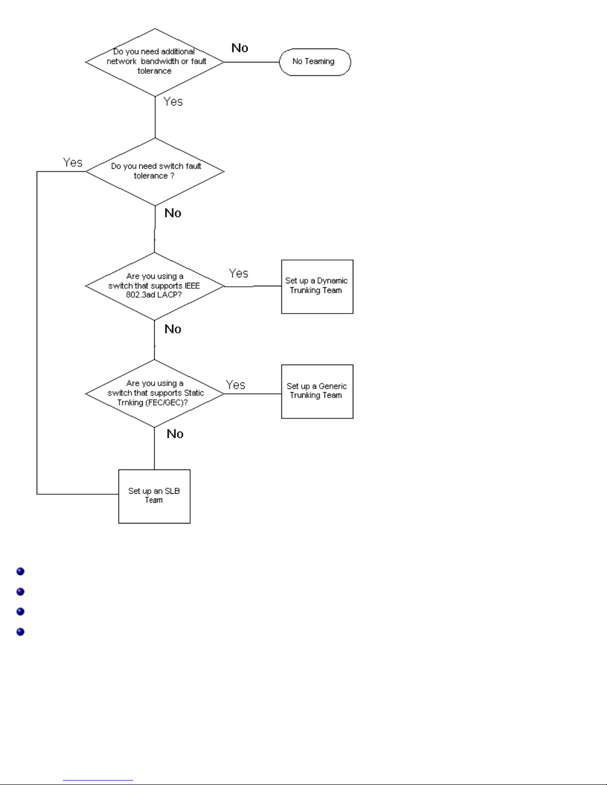
Broadcom Teaming Services: Broadcom NetXtreme II Network Adapter User Guide
Teaming Mechanisms
Architecture
Types of Teams
Attributes of the Features Associated with Each Type of Team
Speeds Supported for Each Type of Team
Architecture
The Broadcom Advanced Server Program is implemented as an NDIS intermediate driver (see Figure 2). It operates below
protocol stacks such as TCP/IP and IPX and appears as a virtual adapter. This virtual adapter inherits the MAC Address of the
first port initialized in the team. A Layer 3 address must also be configured for the virtual adapter. The primary function of
BASP is to balance inbound (for SLB) and outbound traffic (for all teaming modes) among the physical adapters installed on
the system selected for teaming. The inbound and outbound algorithms are independent and orthogonal to each other. The
outbound traffic for a particular session can be assigned to a given port while its corresponding inbound traffic can be
file:///T|/htdocs/NETWORK/BroadCom/71921/NetXtremeII/en/teamsvcs.htm[9/26/2012 3:29:14 PM]
Page 98
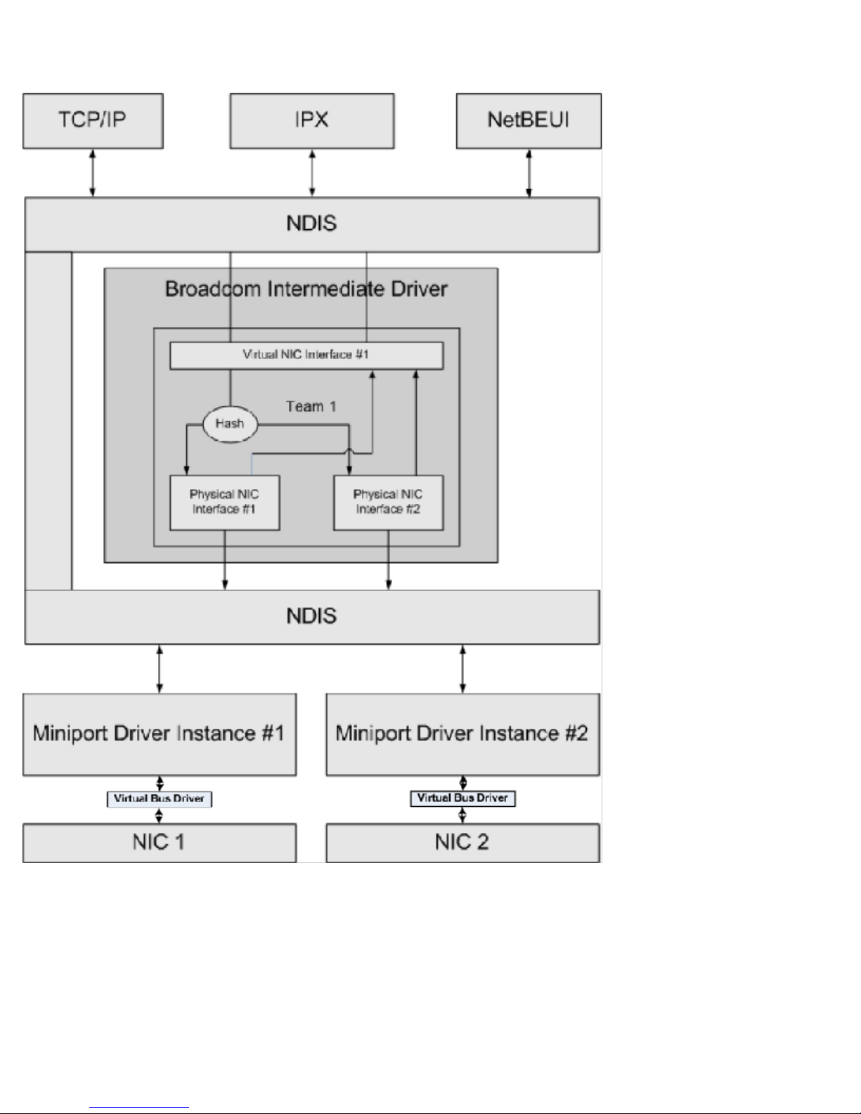
Broadcom Teaming Services: Broadcom NetXtreme II Network Adapter User Guide
assigned to a different port.
Figure 2: Intermediate Driver
Outbound Traffic Flow
The Broadcom Intermediate Driver manages the outbound traffic flow for all teaming modes. For outbound traffic, every
packet is first classified into a flow, and then distributed to the selected physical adapter for transmission. The flow
classification involves an efficient hash computation over known protocol fields. The resulting hash value is used to index into
an Outbound Flow Hash Table.The selected Outbound Flow Hash Entry contains the index of the selected physical adapter
responsible for transmitting this flow. The source MAC address of the packets will then be modified to the MAC address of the
selected physical adapter. The modified packet is then passed to the selected physical adapter for transmission.
The outbound TCP and UDP packets are classified using Layer 3 and Layer 4 header information. This scheme improves the
load distributions for popular Internet protocol services using well-known ports such as HTTP and FTP. Therefore, BASP
file:///T|/htdocs/NETWORK/BroadCom/71921/NetXtremeII/en/teamsvcs.htm[9/26/2012 3:29:14 PM]
Page 99

Broadcom Teaming Services: Broadcom NetXtreme II Network Adapter User Guide
performs load balancing on a TCP session basis and not on a packet-by-packet basis.
In the Outbound Flow Hash Entries, statistics counters are also updated after classification. The load-balancing engine uses
these counters to periodically distribute the flows across teamed ports. The outbound code path has been designed to achieve
best possible concurrency where multiple concurrent accesses to the Outbound Flow Hash Table are allowed.
For protocols other than TCP/IP, the first physical adapter will always be selected for outbound packets. The exception is
Address Resolution Protocol (ARP), which is handled differently to achieve inbound load balancing.
Inbound Traffic Flow (SLB Only)
The Broadcom intermediate driver manages the inbound traffic flow for the SLB teaming mode. Unlike outbound load
balancing, inbound load balancing can only be applied to IP addresses that are located in the same subnet as the loadbalancing server. Inbound load balancing exploits a unique characteristic of Address Resolution Protocol (RFC0826), in which
each IP host uses its own ARP cache to encapsulate the IP Datagram into an Ethernet frame. BASP carefully manipulates the
ARP response to direct each IP host to send the inbound IP packet to the desired physical adapter. Therefore, inbound load
balancing is a plan-ahead scheme based on statistical history of the inbound flows. New connections from a client to the
server will always occur over the primary physical adapter (because the ARP Reply generated by the operating system
protocol stack will always associate the logical IP address with the MAC address of the primary physical adapter).
Like the outbound case, there is an Inbound Flow Head Hash Table. Each entry inside this table has a singly linked list and
each link (Inbound Flow Entries) represents an IP host located in the same subnet.
When an inbound IP Datagram arrives, the appropriate Inbound Flow Head Entry is located by hashing the source IP address
of the IP Datagram. Two statistics counters stored in the selected entry are also updated. These counters are used in the
same fashion as the outbound counters by the load-balancing engine periodically to reassign the flows to the physical
adapter.
On the inbound code path, the Inbound Flow Head Hash Table is also designed to allow concurrent access. The link lists of
Inbound Flow Entries are only referenced in the event of processing ARP packets and the periodic load balancing. There is no
per packet reference to the Inbound Flow Entries. Even though the link lists are not bounded; the overhead in processing
each non-ARP packet is always a constant. The processing of ARP packets, both inbound and outbound, however, depends on
the number of links inside the corresponding link list.
On the inbound processing path, filtering is also employed to prevent broadcast packets from looping back through the
system from other physical adapters.
Protocol Support
ARP and IP/TCP/UDP flows are load balanced. If the packet is an IP protocol only, such as ICMP or IGMP, then all data flowing
to a particular IP address will go out through the same physical adapter. If the packet uses TCP or UDP for the L4 protocol,
then the port number is added to the hashing algorithm, so two separate L4 flows can go out through two separate physical
adapters to the same IP address.
For example, assume the client has an IP address of 10.0.0.1. All IGMP and ICMP traffic will go out the same physical adapter
because only the IP address is used for the hash. The flow would look something like this:
IGMP ------> PhysAdapter1 ------> 10.0.0.1
ICMP ------> PhysAdapter1 ------> 10.0.0.1
If the server also sends an TCP and UDP flow to the same 10.0.0.1 address, they can be on the same physical adapter as
IGMP and ICMP, or on completely different physical adapters from ICMP and IGMP. The stream may look like this:
IGMP ------> PhysAdapter1 ------> 10.0.0.1
ICMP ------> PhysAdapter1 ------> 10.0.0.1
TCP------> PhysAdapter1 ------> 10.0.0.1
UDP------> PhysAdatper1 ------> 10.0.0.1
Or the streams may look like this:
IGMP ------> PhysAdapter1 ------> 10.0.0.1
ICMP ------> PhysAdapter1 ------> 10.0.0.1
file:///T|/htdocs/NETWORK/BroadCom/71921/NetXtremeII/en/teamsvcs.htm[9/26/2012 3:29:14 PM]
Page 100

Broadcom Teaming Services: Broadcom NetXtreme II Network Adapter User Guide
TCP------> PhysAdapter2 ------> 10.0.0.1
UDP------> PhysAdatper3 ------> 10.0.0.1
The actual assignment between adapters may change over time, but any protocol that is not TCP/UDP based goes over the
same physical adapter because only the IP address is used in the hash.
Performance
Modern network interface cards provide many hardware features that reduce CPU utilization by offloading certain CPU
intensive operations (see Teaming and Other Advanced Networking Properties). In contrast, the BASP intermediate driver is a
purely software function that must examine every packet received from the protocol stacks and react to its contents before
sending it out through a particular physical interface. Though the BASP driver can process each outgoing packet in near
constant time, some applications that may already be CPU bound may suffer if operated over a teamed interface. Such an
application may be better suited to take advantage of the failover capabilities of the intermediate driver rather than the load
balancing features, or it may operate more efficiently over a single physical adapter that provides a particular hardware
feature such as Large Send Offload.
Types of Teams
Switch-Independent
The Broadcom Smart Load Balancing type of team allows two to eight physical adapters to operate as a single virtual adapter.
The greatest benefit of the SLB type of team is that it operates on any IEEE compliant switch and requires no special
configuration.
Smart Load Balancing and Failover
SLB provides for switch-independent, bidirectional, fault-tolerant teaming and load balancing. Switch independence implies
that there is no specific support for this function required in the switch, allowing SLB to be compatible with all switches. Under
SLB, all adapters in the team have separate MAC addresses. The load-balancing algorithm operates on Layer 3 addresses of
the source and destination nodes, which enables SLB to load balance both incoming and outgoing traffic.
The BASP intermediate driver continually monitors the physical ports in a team for link loss. In the event of link loss on any
port, traffic is automatically diverted to other ports in the team. The SLB teaming mode supports switch fault tolerance by
allowing teaming across different switches- provided the switches are on the same physical network or broadcast domain.
Network Communications
The following are the key attributes of SLB:
Failover mechanism – Link loss detection.
Load Balancing Algorithm – Inbound and outbound traffic are balanced through a Broadcom proprietary mechanism
based on L4 flows.
Outbound Load Balancing using MAC Address - No.
Outbound Load Balancing using IP Address - Yes
Multivendor Teaming – Supported (must include at least one Broadcom Ethernet adapter as a team member).
Applications
The SLB algorithm is most appropriate in home and small business environments where cost is a concern or with commodity
switching equipment. SLB teaming works with unmanaged Layer 2 switches and is a cost-effective way of getting redundancy
and link aggregation at the server. Smart Load Balancing also supports teaming physical adapters with differing link
capabilities. In addition, SLB is recommended when switch fault tolerance with teaming is required.
Configuration Recommendations
SLB supports connecting the teamed ports to hubs and switches if they are on the same broadcast domain. It does not
support connecting to a router or Layer 3 switches because the ports must be on the same subnet.
Switch-Dependent
Generic Static Trunking
file:///T|/htdocs/NETWORK/BroadCom/71921/NetXtremeII/en/teamsvcs.htm[9/26/2012 3:29:14 PM]
 Loading...