

Page 1

Dell EMC DSS 9000R
Regulatory Model: B11S Series Series
Regulatory Type: B11S001
Page 2

Notes, cautions, and warnings
NOTE: A NOTE indicates important information that helps you make better use of your product.
CAUTION: A CAUTION indicates either potential damage to hardware or loss of data and tells you how to avoid the problem.
WARNING: A WARNING indicates a potential for property damage, personal injury, or death.
Copyright © 2018 Dell Inc. or its subsidiaries. All rights reserved. Dell, EMC, and other trademarks are trademarks of Dell Inc. or its subsidiaries. Other
trademarks may be trademarks of their respective owners.
2018 - 01
Rev. A00
Page 3

Contents
1 Overview........................................................................................................................................................6
Rack specications.............................................................................................................................................................7
2 Rack accessories overview............................................................................................................................ 8
Server blanks...................................................................................................................................................................... 8
Power supply unit (PSU) blanks (optional)................................................................................................................... 14
Side panels (optional).......................................................................................................................................................15
Shipping brackets............................................................................................................................................................. 16
PDU brackets....................................................................................................................................................................18
Power bay protectors......................................................................................................................................................20
Bus bar protectors............................................................................................................................................................ 21
Rack blank llers...............................................................................................................................................................23
IM blank llers...................................................................................................................................................................27
Locating Service Tag of your system.............................................................................................................................28
3 Rear cabinet overview................................................................................................................................. 30
Rear cabinet specications.............................................................................................................................................32
Block control distribution board..................................................................................................................................... 34
Block controller (BC) modules....................................................................................................................................... 36
Fan power distribution boards (FPDB)......................................................................................................................... 38
Fan modules..................................................................................................................................................................... 40
4 Power bay overview..................................................................................................................................... 41
Power bay specications................................................................................................................................................ 43
Power bay unit..................................................................................................................................................................44
Power bay allocation..................................................................................................................................................44
Rear view.................................................................................................................................................................... 46
Power supply unit (PSU).......................................................................................................................................... 48
Power bay power module (PBPM)..........................................................................................................................50
Management controller (MC) module..................................................................................................................... 51
Rear IO module...........................................................................................................................................................53
DSS 9000 rack manager module.............................................................................................................................55
5 Bus bar overview......................................................................................................................................... 57
Rack level bus bar............................................................................................................................................................ 57
Bus bar top..................................................................................................................................................................57
Bus bar middle............................................................................................................................................................58
Bus bar bottom........................................................................................................................................................... 61
Block level bus bar............................................................................................................................................................61
One third-width cross bus bar block....................................................................................................................... 62
Half-width/full-width cross bus bar block.............................................................................................................. 63
Power bay level bus bars.................................................................................................................................................67
Installation and Service Manual
Contents
3
Page 4

Bus bar-PB..................................................................................................................................................................68
6 Installing and removing system components................................................................................................ 70
Safety instructions...........................................................................................................................................................70
Recommended tools........................................................................................................................................................70
Service parts list...............................................................................................................................................................70
Servers...............................................................................................................................................................................71
Removing one third-width server............................................................................................................................. 71
Installing one third-width server...............................................................................................................................73
Removing half-width server......................................................................................................................................75
Installing half-width server........................................................................................................................................ 77
Removing full-width server.......................................................................................................................................79
Installing full-width server.........................................................................................................................................79
Hard disk drive (HDD) trays............................................................................................................................................ 81
Removing HDD tray....................................................................................................................................................81
Installing HDD tray..................................................................................................................................................... 85
Power supply units (PSU).............................................................................................................................................. 90
Removing PSU............................................................................................................................................................91
Installing PSU..............................................................................................................................................................93
Fan modules..................................................................................................................................................................... 95
Removing fan module................................................................................................................................................96
Installing fan module..................................................................................................................................................98
Fan blocks....................................................................................................................................................................... 100
Removing fan block..................................................................................................................................................100
Installing fan block.................................................................................................................................................... 102
Fan power distribution boards (FPDB)........................................................................................................................104
Removing FPDB....................................................................................................................................................... 105
Installing FPDB..........................................................................................................................................................107
Block Controller Distribution Board (BCDB).................................................................................................................111
Removing BCDB........................................................................................................................................................ 111
Installing BCDB................................................................................................................................................................ 117
Block controllers (BC).................................................................................................................................................... 119
Removing BC.............................................................................................................................................................119
Installing BC............................................................................................................................................................... 121
Management controllers (MC)..................................................................................................................................... 123
Removing MC........................................................................................................................................................... 123
Installing MC..............................................................................................................................................................125
Rack manager board (RMB) and infrastructure module (IM)...................................................................................127
Removing DSS 9000 rack manager module......................................................................................................... 127
Installing DSS 9000 rack manager module............................................................................................................129
Removing IM..............................................................................................................................................................131
Installing IM............................................................................................................................................................... 133
Rear IO modules............................................................................................................................................................. 135
Removing rear IO module........................................................................................................................................135
Installing rear IO module.......................................................................................................................................... 135
Power interface board (PIB)......................................................................................................................................... 137
4
Installation and Service Manual
Contents
Page 5

Removing PIB............................................................................................................................................................137
Installing PIB.............................................................................................................................................................. 147
7 Troubleshooting list.................................................................................................................................... 158
8 Getting help............................................................................................................................................... 160
Contacting Dell............................................................................................................................................................... 160
Documentation feedback.............................................................................................................................................. 160
Installation and Service Manual
Contents
5
Page 6
Overview
The DSS 9000 rack enclosure is designed to hold and protect server, network, and data storage equipment.
NOTE: The product at time of delivery may dier from the following illustrations.
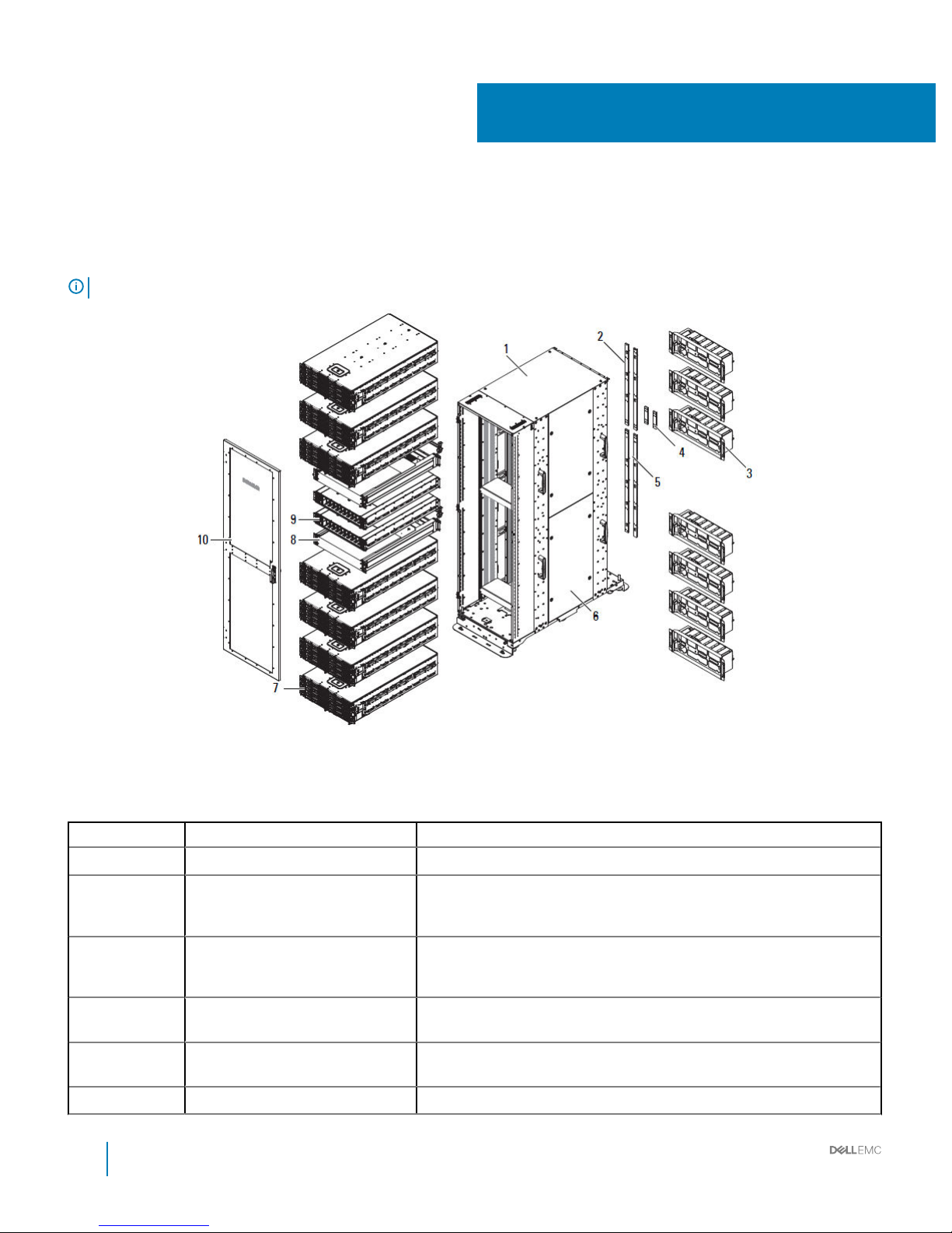
Figure 1. DSS 9000 system
Table 1. DSS 9000 features
No. Feature Description
1 Bare rack Rack mounting enclosure for DSS 9000 system equipment.
2 Bus bar top Bar strip located on top of the rack conducts electricity. Based on rack layout,
two dierent types of top bus bars can be assembled. For more information
about bus bars, see Bus bar top.
3 Rear cabinet The rear cabinet houses twelve system fans, one block controller distribution
board (BCDB), one block controller (BC), one fan cage, one fan power
distribution board (FPDB), and one rear cabinet base.
4 Bus bar middle Bridge bus bar located between top and bottom bus bars. For more
information about bus bars, see Bus bar middle.
5 Bus bar bottom Bar strip located on bottom of the rack conducts electricity. For more
information about bus bars, see Bus bar bottom.
6 Side panel (optional) Rack cabinet ller panel (optional).
1
6 Installation and Service Manual
Overview
Page 7
No. Feature Description
7 Block chassis Three types of block chassis (one third-width, half-width, and full-width).
8 OpenIT bay Two switch devices are available to provide networking for the entire system.
9 Power Bay Located on the front side of rack, provides allocated space for power supply
units (PSUs).
10 Front door (optional) Reversible front door can be congured to open from left or right, with lock.
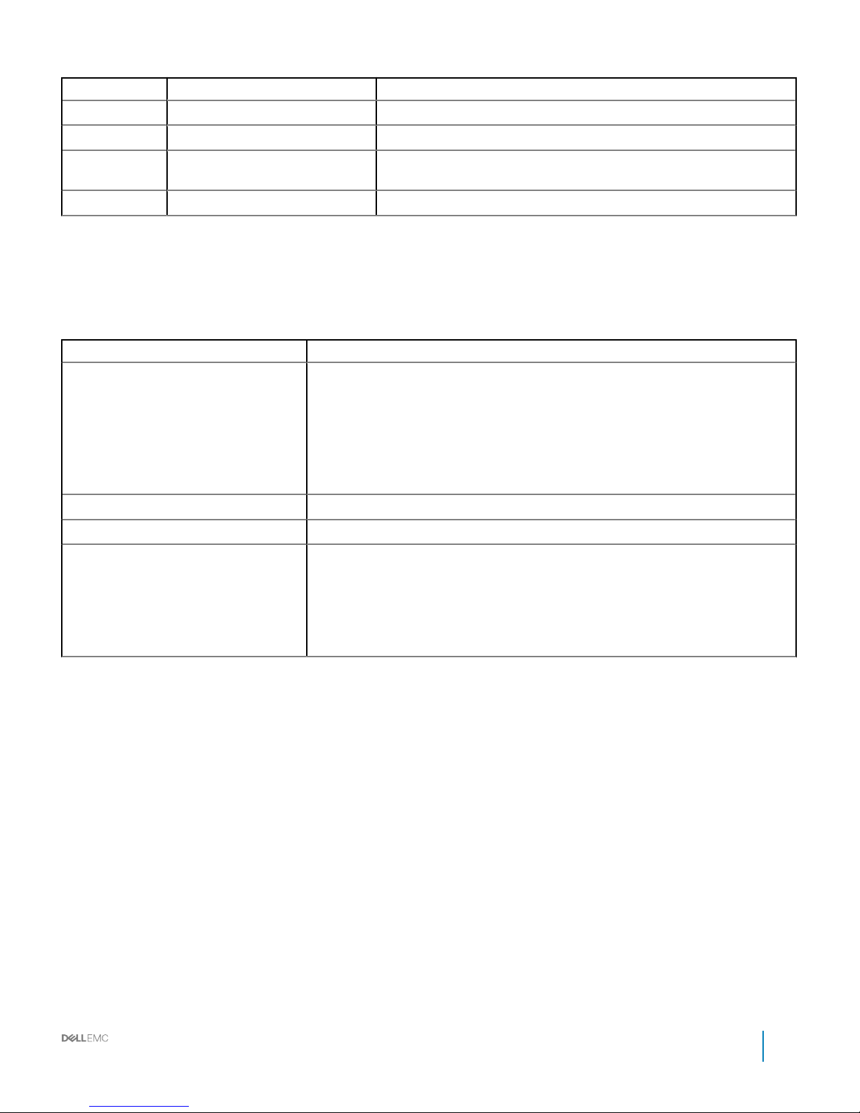
Rack specications
Table 2. Rack specications
Item Description
Height Available rack options:
• 29U: 1,466.4 mm (57.73 inch)
• 42U: 1,970.4 mm (77.57 inch)
• 44U: 2,071.2 mm (81.54 inch)
• 48U: 2,272.8 mm (89.48 inch)
• 50U: 2,373.6 mm (93.45 inch)
Width 600 mm (23.62 inch)
Depth 1,200 mm (47.24 inch)
Net weight
• 29U: 162.4 kg (358 lb)
• 42U: 201.4 kg (444 lb)
• 44U: 207.3 kg (457 lb)
• 48U: 219.1 kg (483 lb)
• 50U: 225.0 kg (496 lb)
Installation and Service Manual
Overview
7
Page 8

Rack accessories overview
The DSS 9000 rack enclosure oers server and power supply blanks as well as shipping brackets, bus bar protectors and optional side
panel accessories.
Topics:
• Server blanks
• Power supply unit (PSU) blanks (optional)
• Side panels (optional)
• Shipping brackets
• PDU brackets
• Power bay protectors
• Bus bar protectors
• Rack blank llers
• IM blank llers
• Locating Service Tag of your system
Server blanks
The following lists the available server blanks for the DSS 9000: full width, half width, and one third width blank chassis.
2
8 Installation and Service Manual
Rack accessories overview
Page 9

Figure 2. Full-width server blank
Installation and Service Manual
Rack accessories overview
9
Page 10
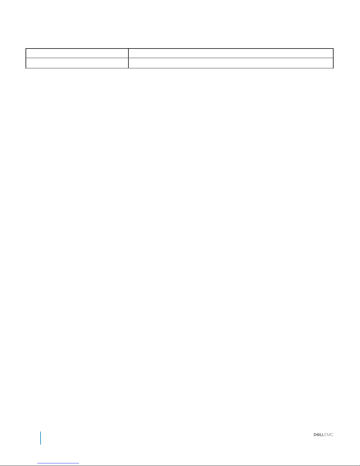
Table 3. Full-width server blank features
Item Description
Dimensions (W x L x H) 527 mm x 930 mm x 47 mm (20.75 inch x 36.61 inch x 1.85 inch)
10 Installation and Service Manual
Rack accessories overview
Page 11
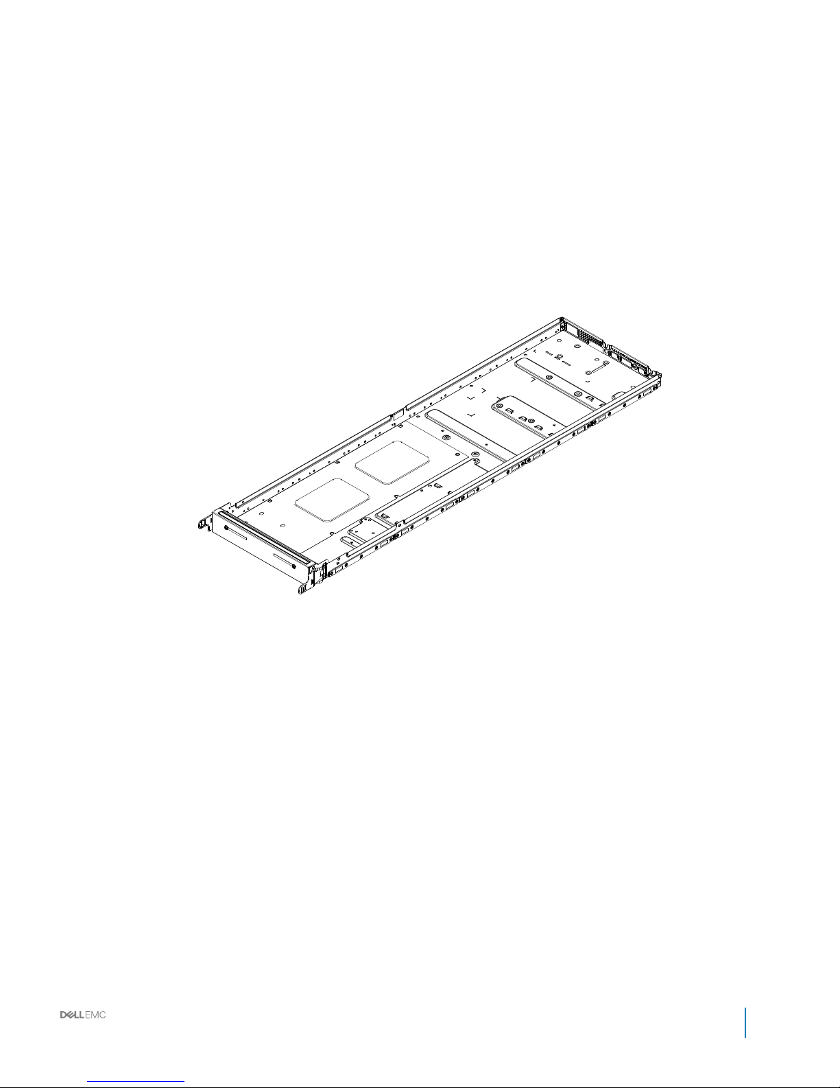
Figure 3. Half-width server blank
Installation and Service Manual
Rack accessories overview
11
Page 12
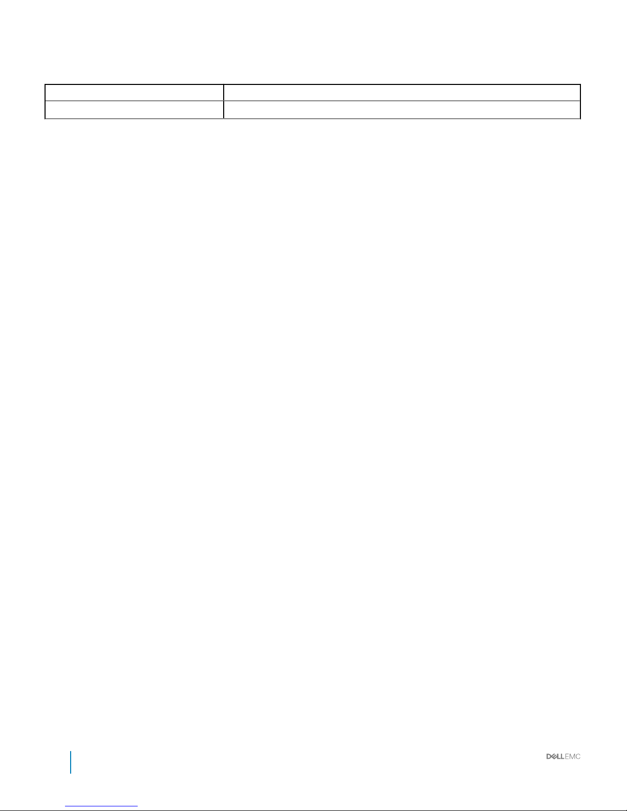
Table 4. Full-width server blank features
Item Description
Dimensions (W x L x H) 262.2 mm x 930 mm x 47 mm (10.32 inch x 36.61 inch x 1.85 inch)
12 Installation and Service Manual
Rack accessories overview
Page 13
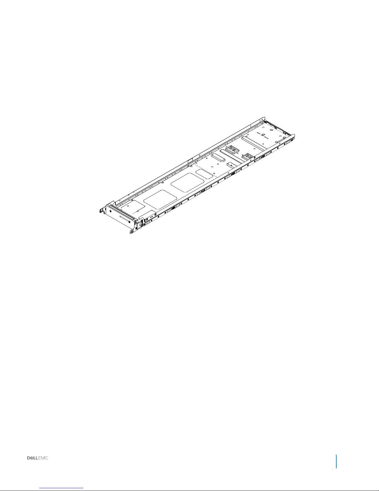
Figure 4. One third-width server blank
Installation and Service Manual
Rack accessories overview
13
Page 14
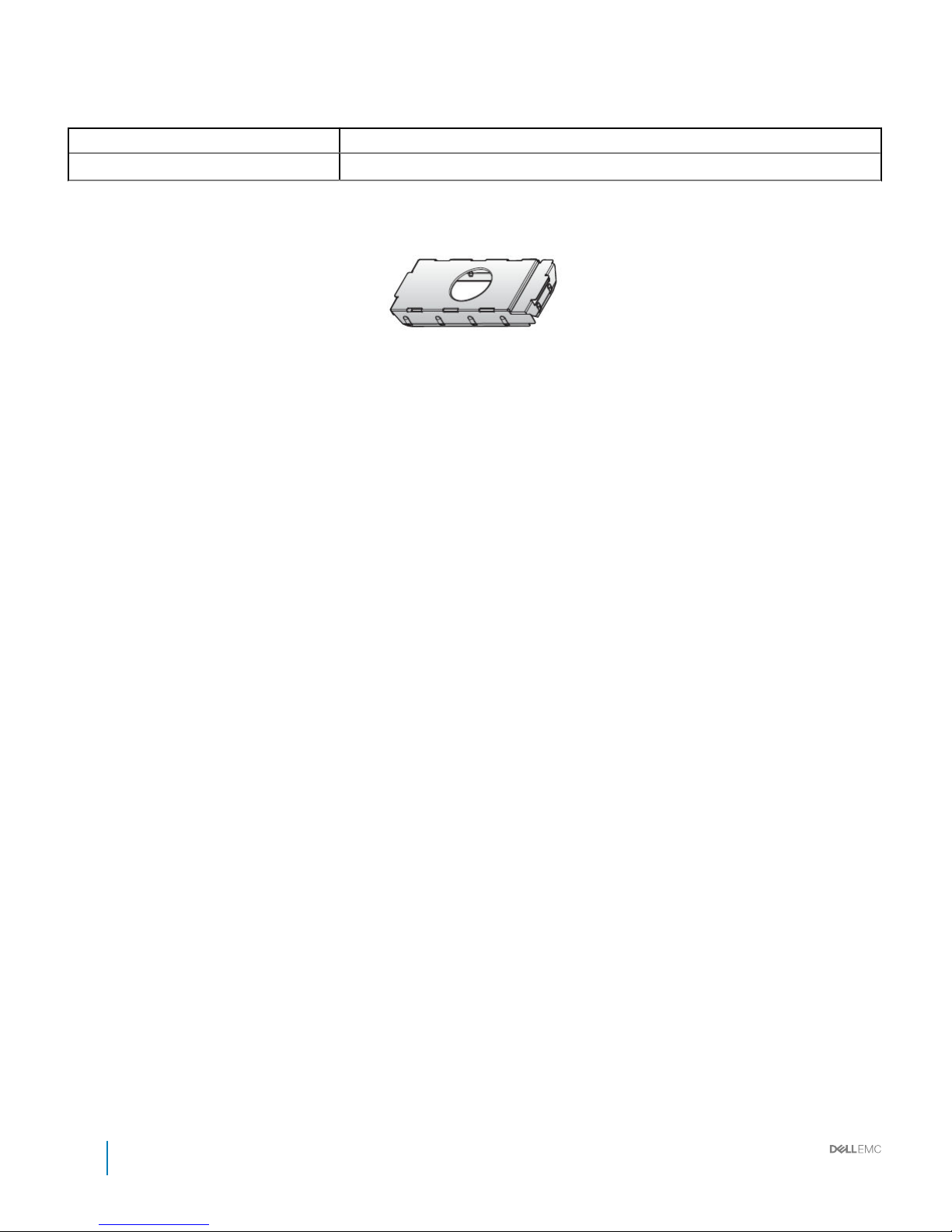
Table 5. Full-width server blank features
Item Description
Dimensions (W x L x H) 174.3 mm x 930 mm x 47 mm (6.86 inch x 36.61 inch x 1.85 inch)
Power supply unit (PSU) blanks (optional)
Figure 5. PSU blank
14 Installation and Service Manual
Rack accessories overview
Page 15
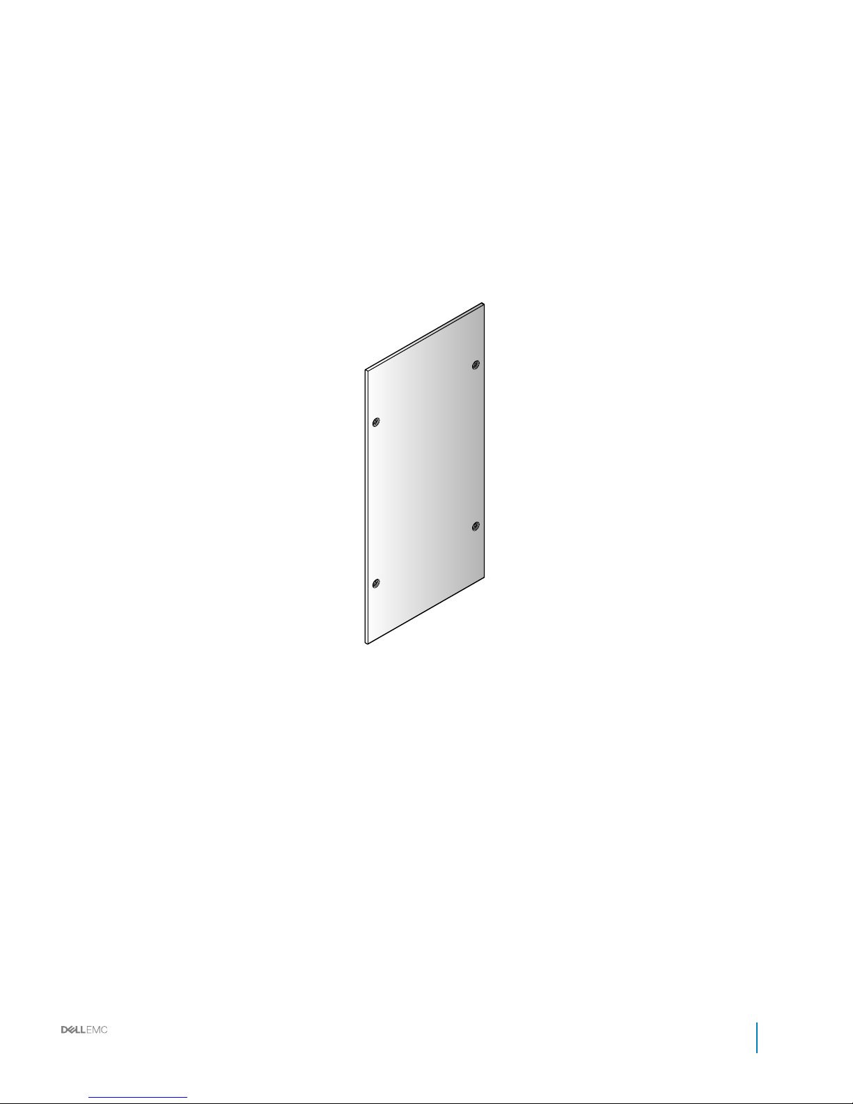
Side panels (optional)
Figure 6. Filler panel
Installation and Service Manual
Rack accessories overview
15
Page 16
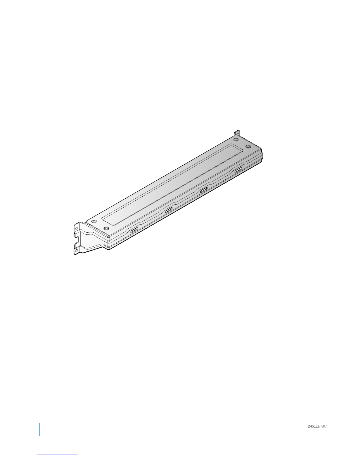
Shipping brackets
Figure 7. Shipping bracket
16
Installation and Service Manual
Rack accessories overview
Page 17
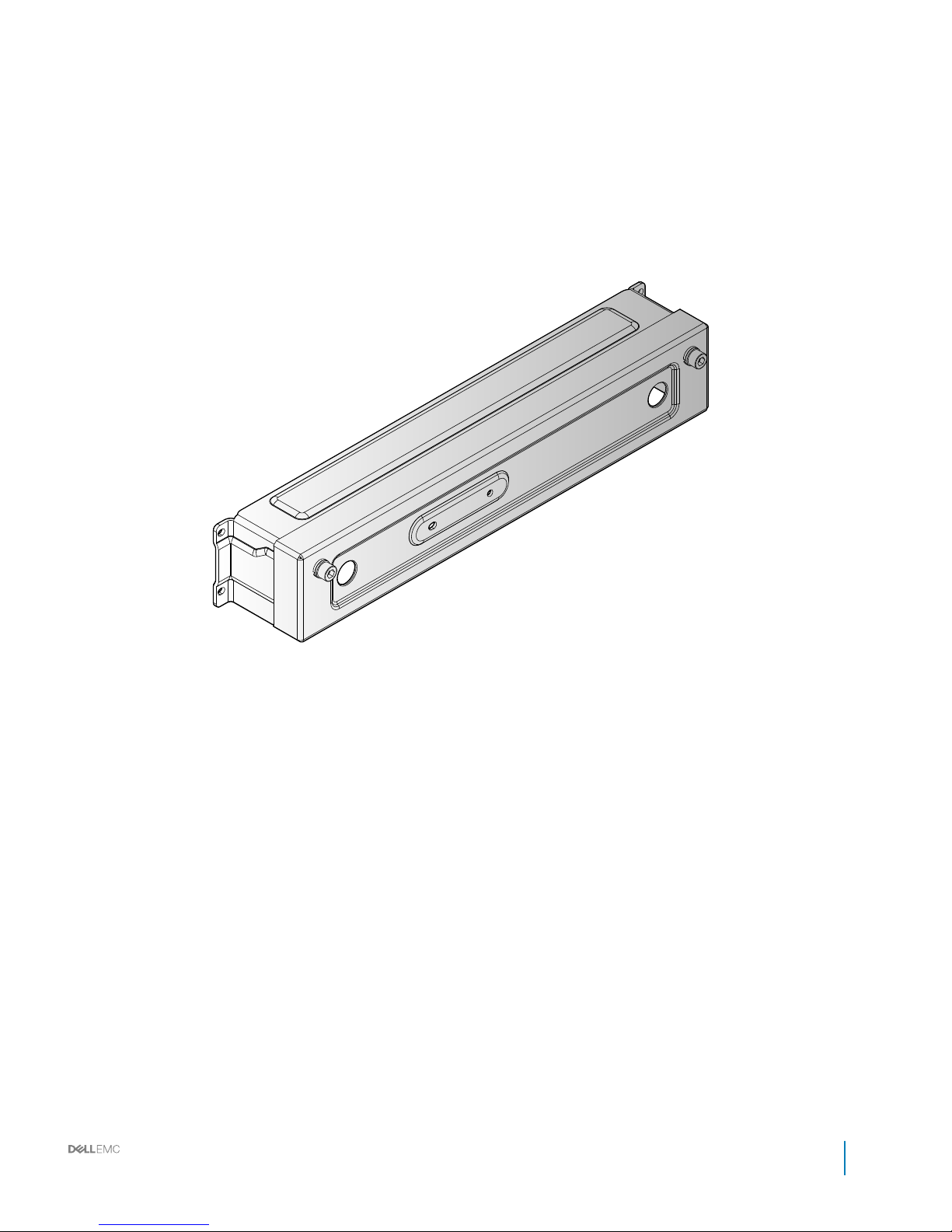
Figure 8. Shipping bracket
Installation and Service Manual
Rack accessories overview
17
Page 18
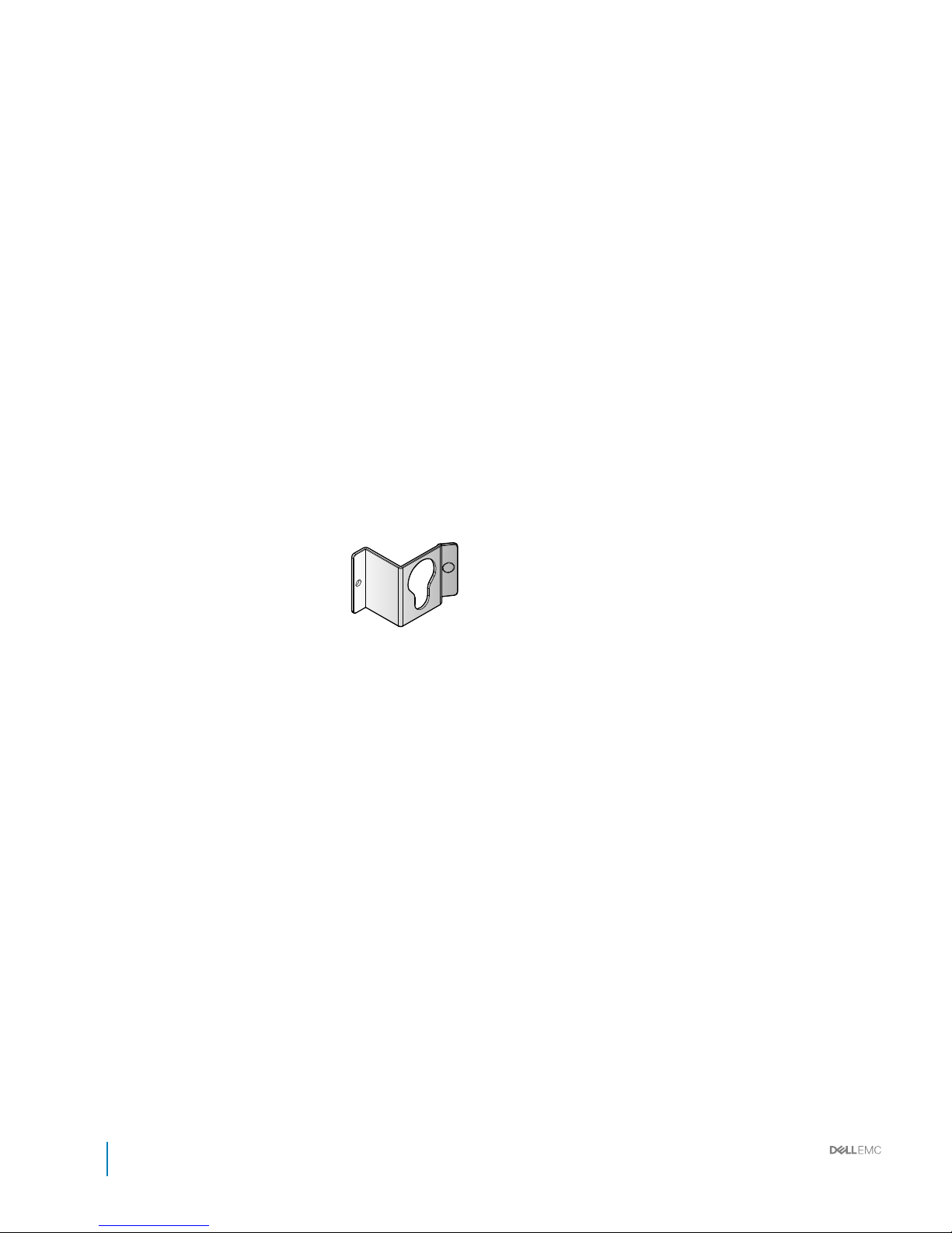
PDU brackets
18 Installation and Service Manual
Rack accessories overview
Page 19
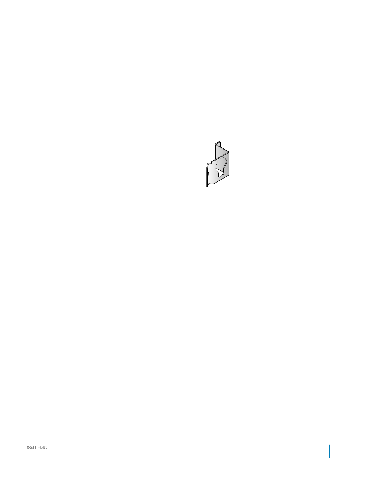
Figure 9. PDU bracket
Installation and Service Manual
Rack accessories overview
19
Page 20
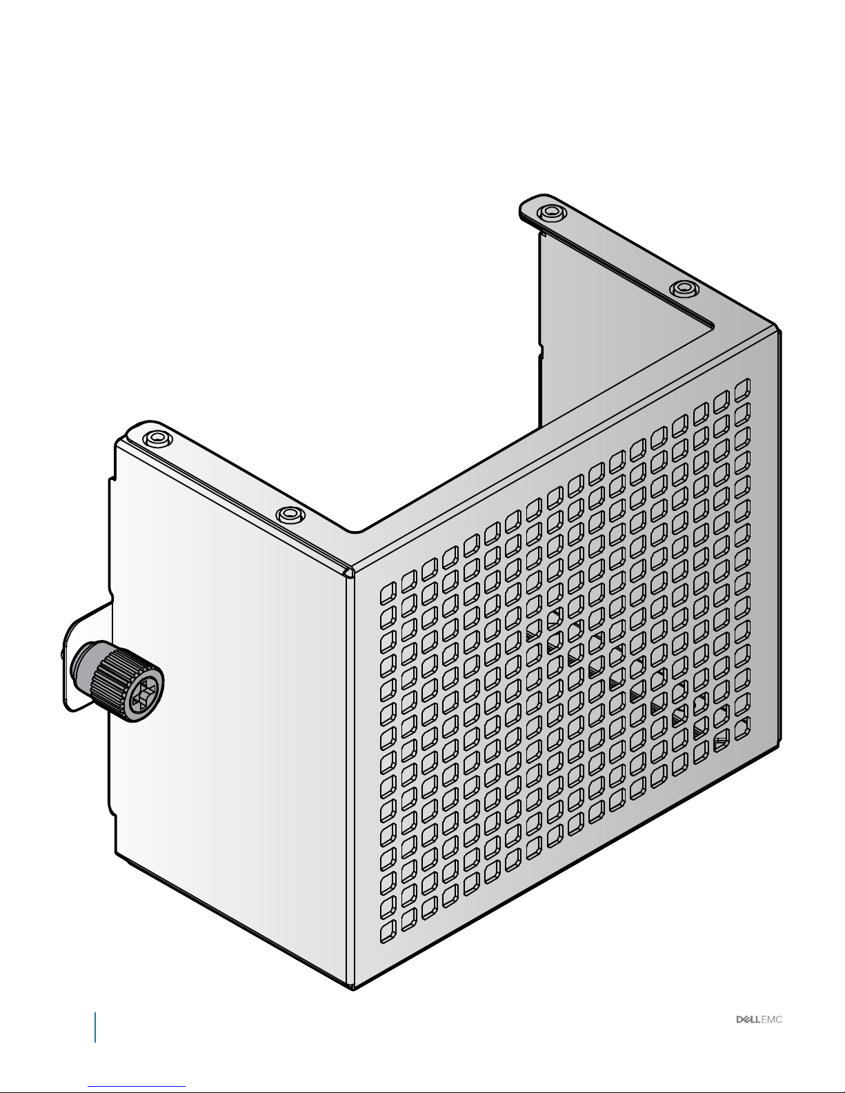
Power bay protectors
Figure 10. Power bay protector
20
Installation and Service Manual
Rack accessories overview
Page 21
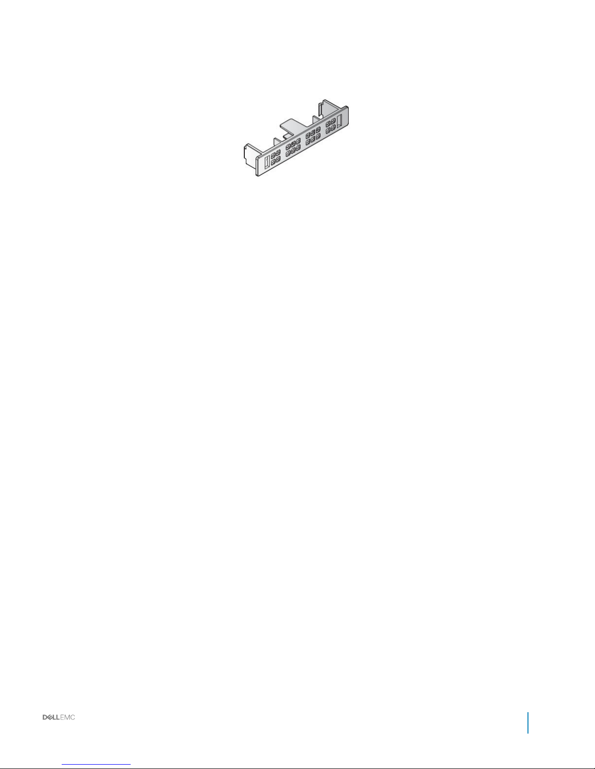
Bus bar protectors
Figure 11. 0.5GU bus bar protector
Installation and Service Manual
Rack accessories overview
21
Page 22
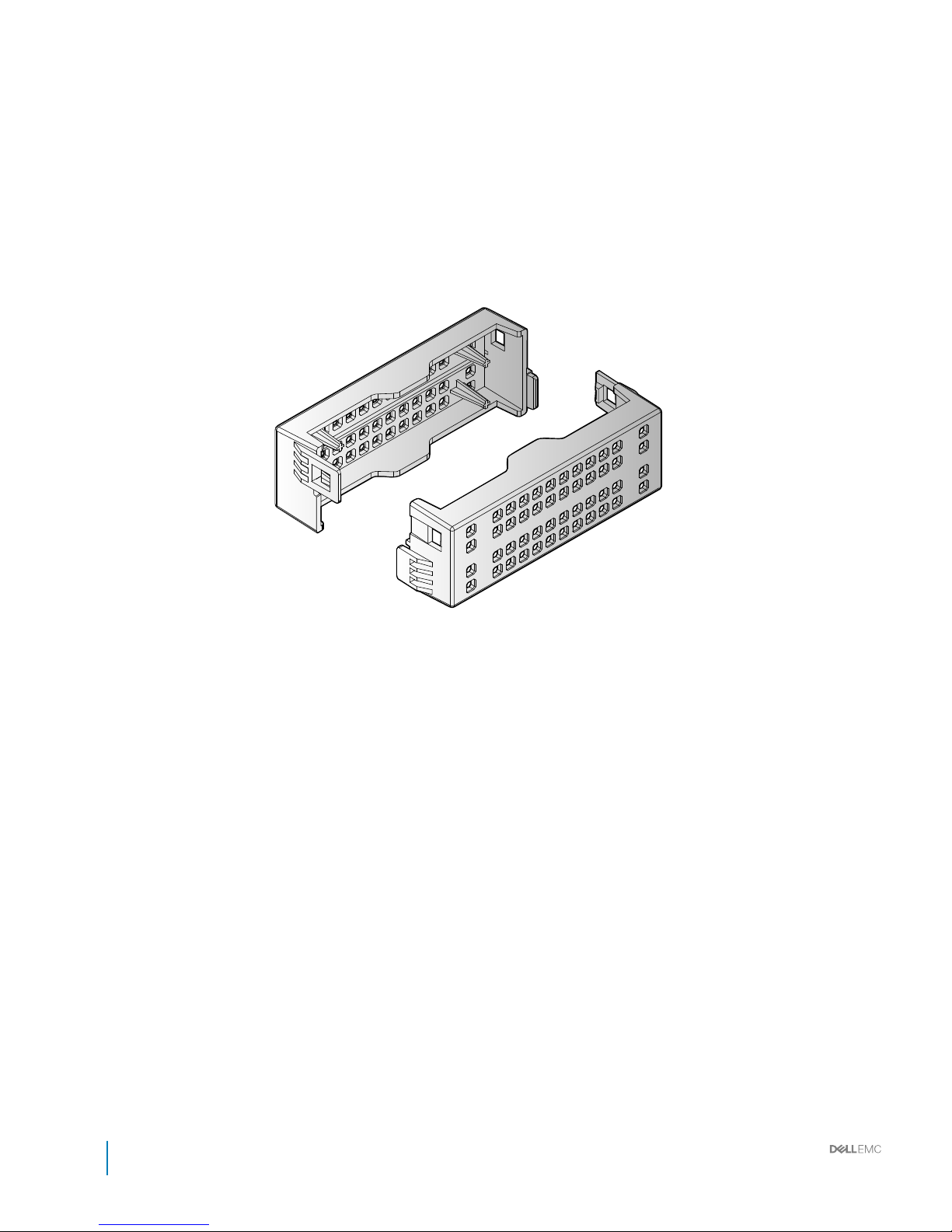
Figure 12. 1GU bus bar protector
22
Installation and Service Manual
Rack accessories overview
Page 23
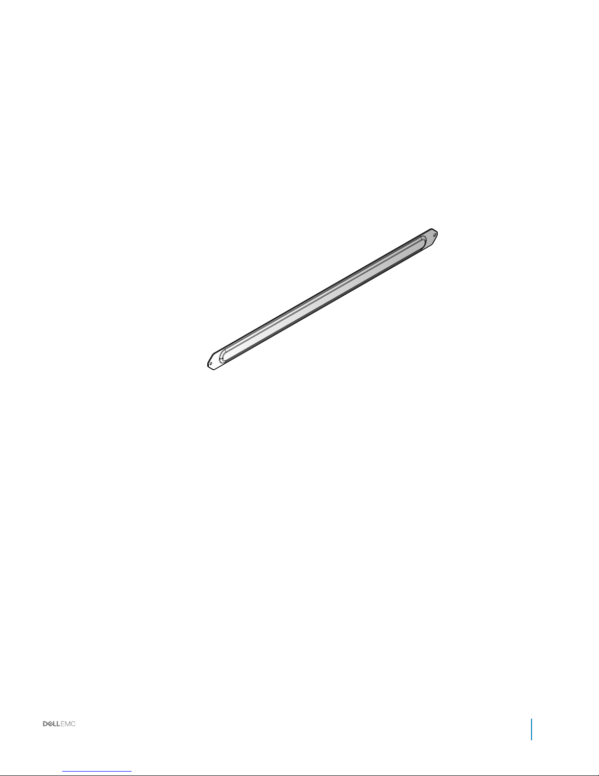
Rack blank llers
Figure 13. 1GU rack blank llers
Installation and Service Manual
Rack accessories overview
23
Page 24
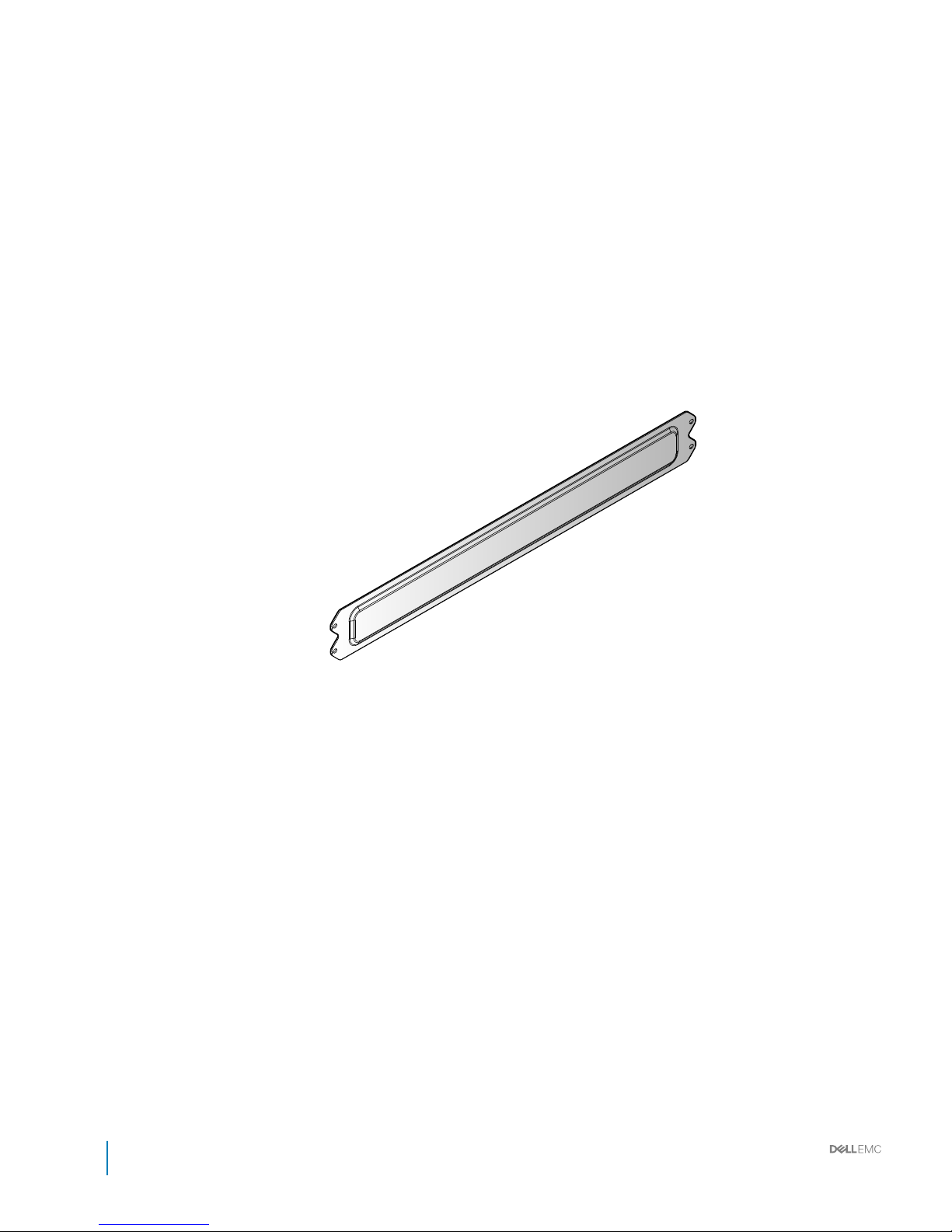
Figure 14. 2GU rack blank llers
24
Installation and Service Manual
Rack accessories overview
Page 25

Figure 15. 3GU rack blank llers
Installation and Service Manual
Rack accessories overview
25
Page 26
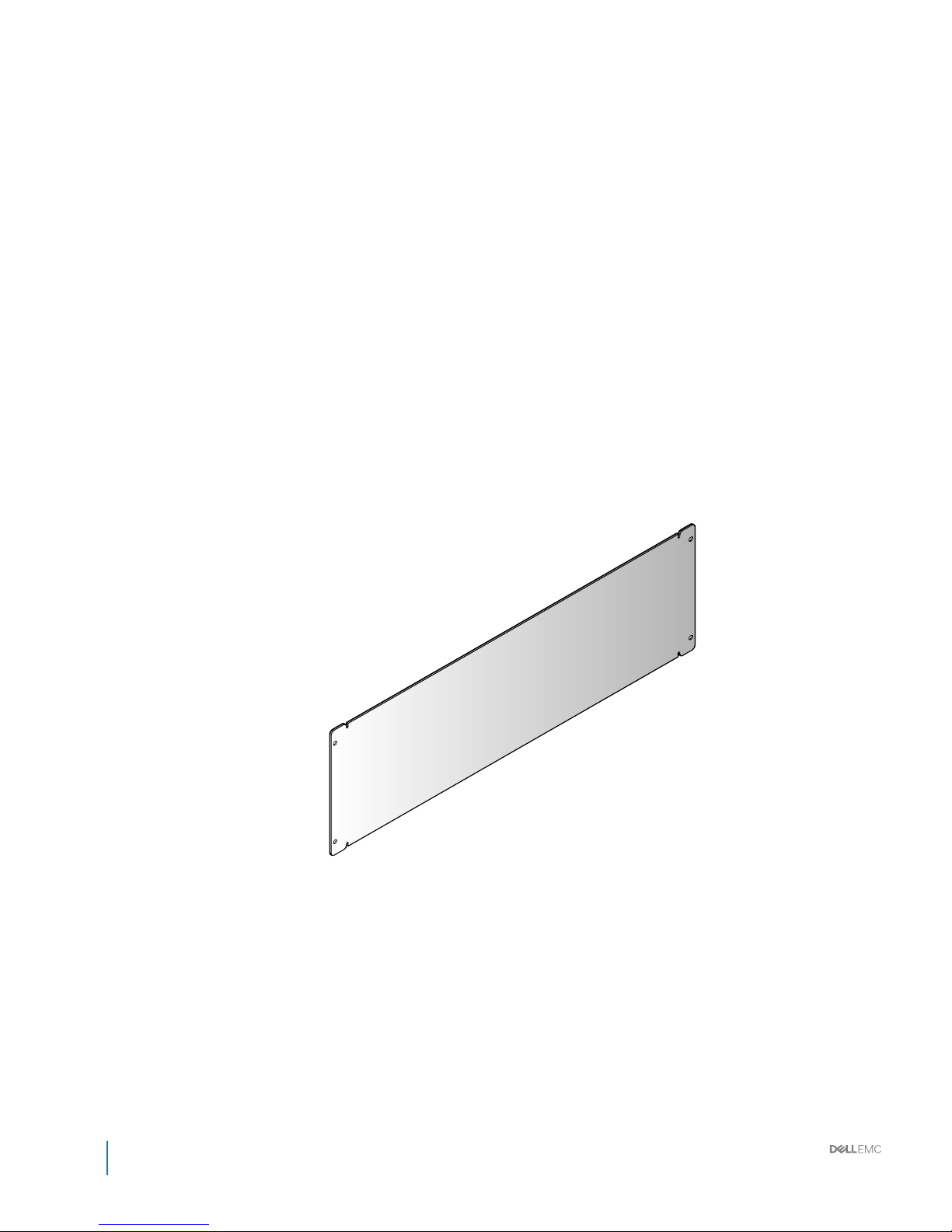
Figure 16. 5GU rack blank llers
26
Installation and Service Manual
Rack accessories overview
Page 27
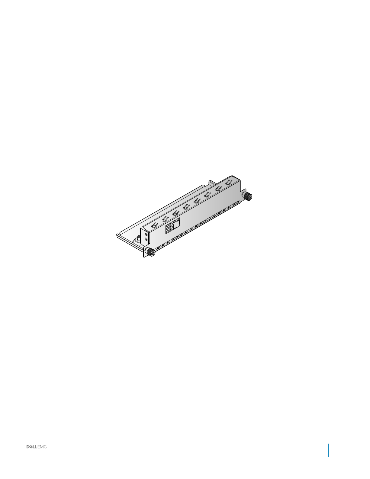
IM blank llers
Figure 17. IM blank llers
Installation and Service Manual
Rack accessories overview
27
Page 28

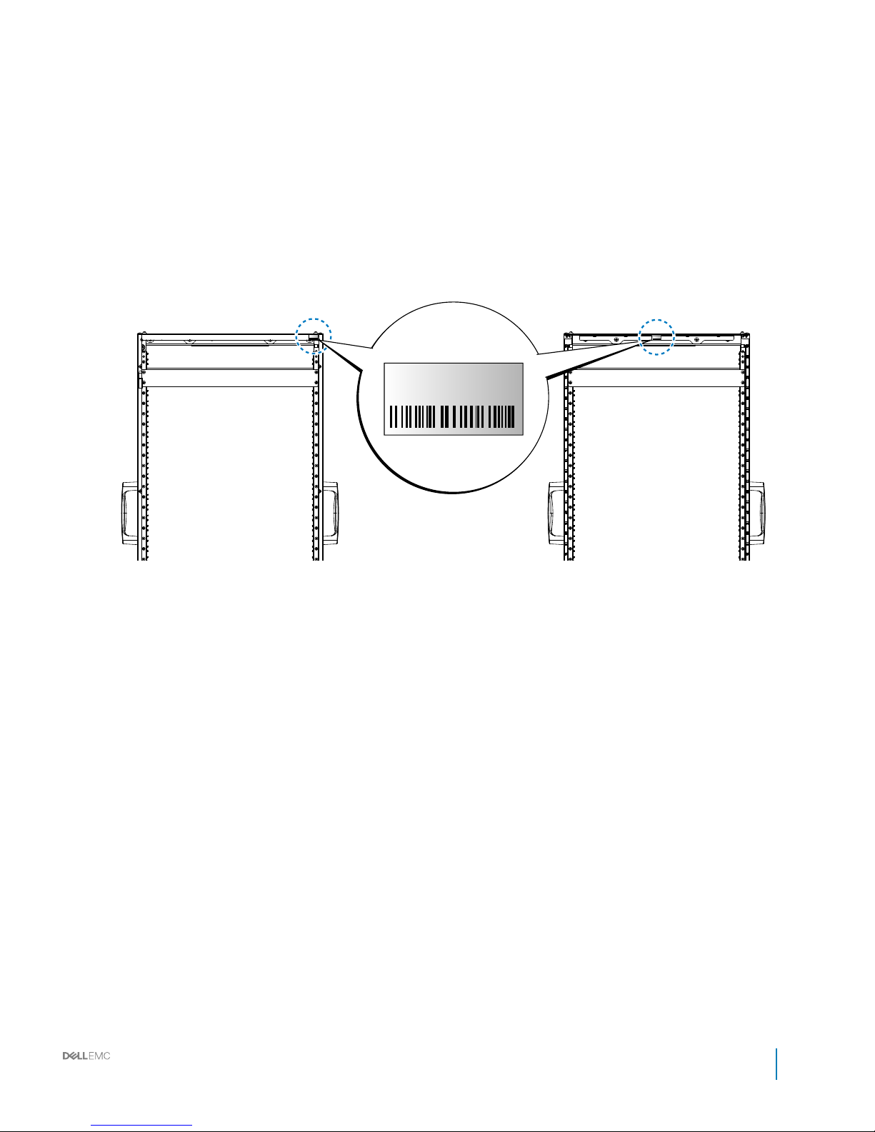
Locating Service Tag of your system
Your system is identied by a unique Express Service Code and Service Tag number. The information is on a sticker on the right-front of the
system. This information is used by Dell to route support calls to the appropriate personnel.
28 Installation and Service Manual
Rack accessories overview
Page 29
Service Tag
BMMYG92
Service Tag
BMMYG92
Service Tag
BMMYG92
Figure 18. Service Tag location
Installation and Service Manual
Rack accessories overview
29
Page 30
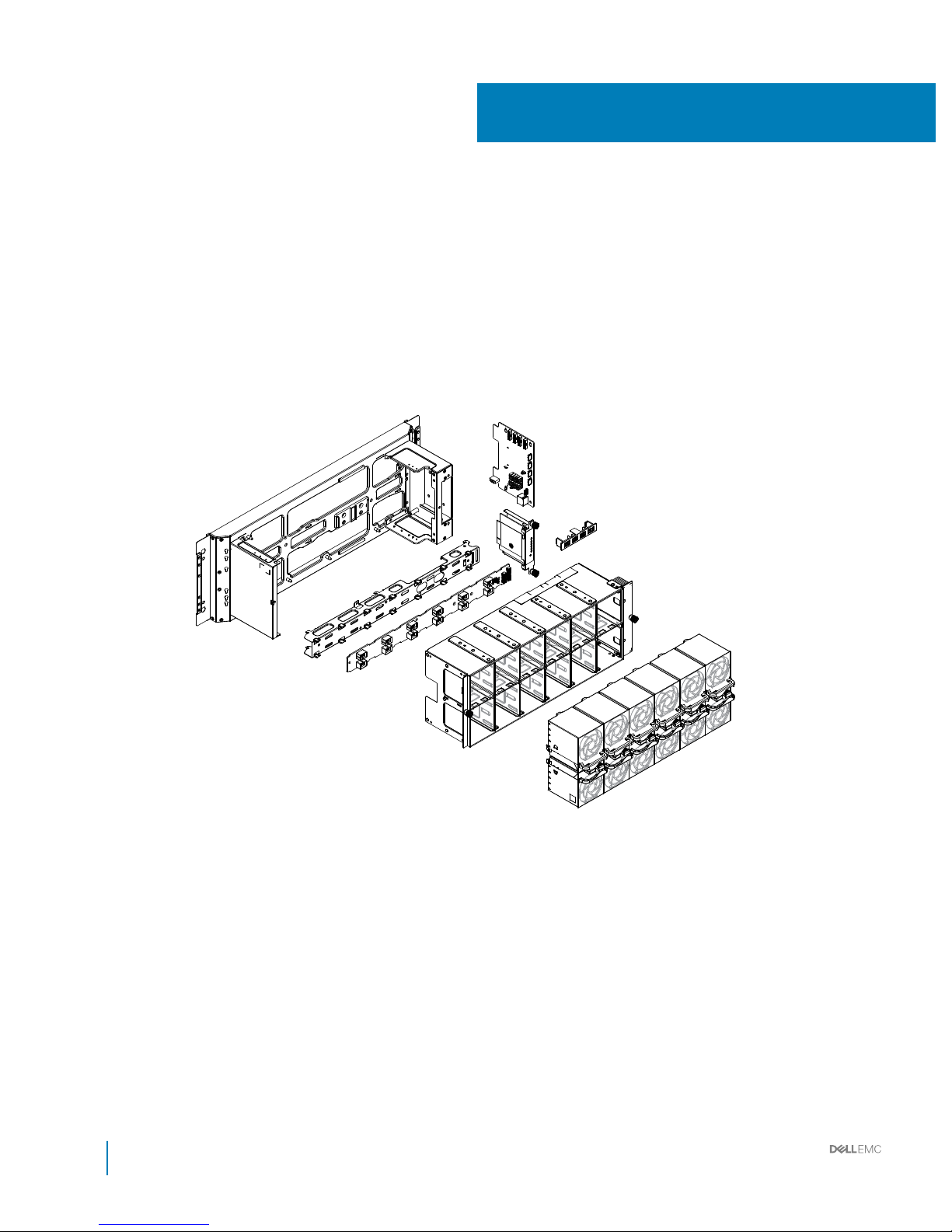
Rear cabinet overview
3
30 Installation and Service Manual
Rear cabinet overview
Page 31

Table 6. Rear cabinet features
No. Item Description
1 BCDB (Block Controller Distribution
Board)
• 1 x PCIe x8 connector
• 4 x Fan zone connector
• 4 x PIB connector
• 1 x RJ45
• 1 x Temperature sensor connector
2 0.5U bus bar protector Cover to prevent contact with the bus bar.
3 BC (Block Controller) Connectors
• 1 x PCIe x8 golden nger
• 1 x RS232
• 1 x JTAG
LED
• 1 x power / status
• 1 x ID
• 4 x fan fail
Switch
• Reset switch (local)
4 Fan cage Supports up to twelve fan modules
• Width: 480 mm (18.89 inch)
• Length: 114.5 mm (4.50 inch)
• Height: 116.0 mm (4.56 inch)
5 Fan modules Fan module includes twelve fans.
6 FPDB (Fan Power Distribution Board)
• 1 x 2x13 connector
• 1 x 2x10 connector
• 12 x 2x4 connectors
7 Rear cabinet base Supports up to twelve fan modules
Topics:
• Rear cabinet specications
• Block control distribution board
• Block controller (BC) modules
• Fan power distribution boards (FPDB)
• Fan modules
Installation and Service Manual
Rear cabinet overview
31
Page 32
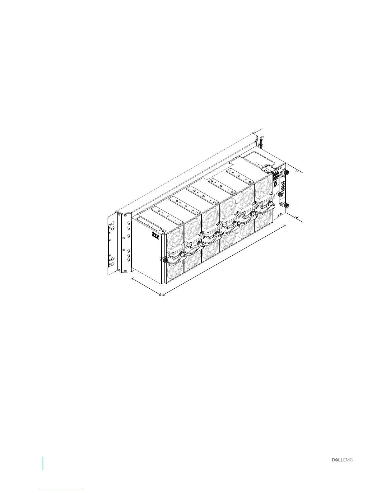
Rear cabinet specications
Figure 20. Rear cabinet
32
Installation and Service Manual
Rear cabinet overview
Page 33
Table 7. Rear cabinet
Item Description
Rear cabinet Includes fan modules, fan cage, FPDB, BC, BCDB, and power strip brackets.
Dimensions (W x L x H) 480 mm x 114.5 mm x 167 mm (18.9 inch x 4.51 inch x 6.57 inch)
Installation and Service Manual
Rear cabinet overview
33
Page 34
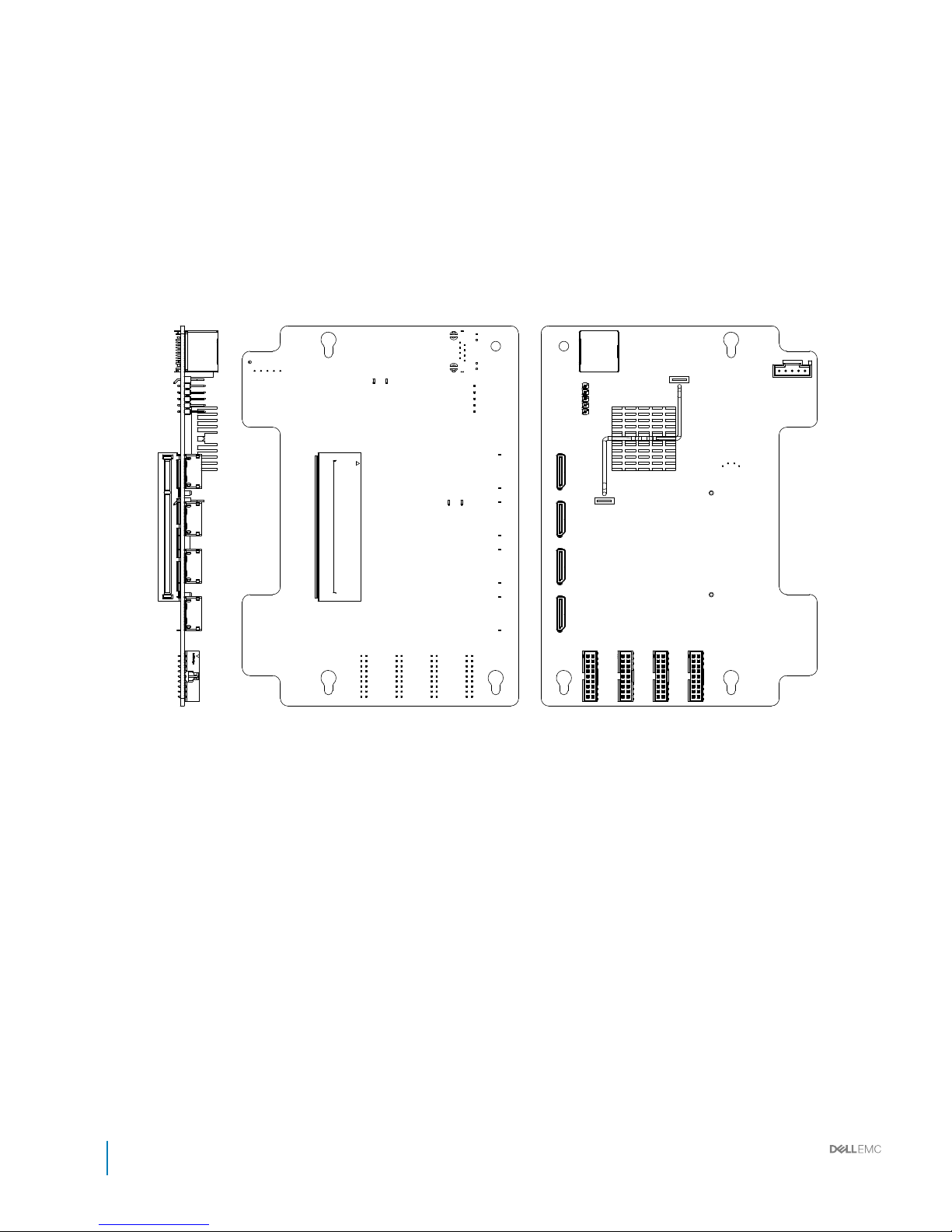
Block control distribution board
Figure 21. Block control distribution board
34
Installation and Service Manual
Rear cabinet overview
Page 35
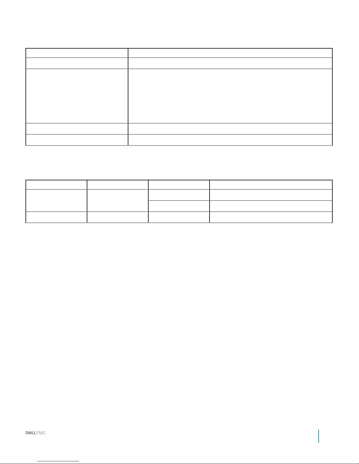
Table 8. Block control distribution board
Item Description
Dimension (W x L x H) 150 mm x 109 mm x 1.5 mm (5.90 inch x 4.29 inch x 0.06 inch), 8 layers
Connector
• 4 x FAN Zone connector
• 1 x RJ45
• 4 x NPIO connector
• 1 x HTPB connector
• 1 x BC connector
• 1 x BCM UART connector
Net weight 78.6 g (2.77 ounce)
Operating voltage/current 12 V, current 0.2 A
LED denition
Table 9. LED
LED Color Status Description
LED (Left) Amber Solid Link speed: 100Mb
O Disconnected
LED (Right) Green Blinking LAN access
Installation and Service Manual
Rear cabinet overview
35
Page 36
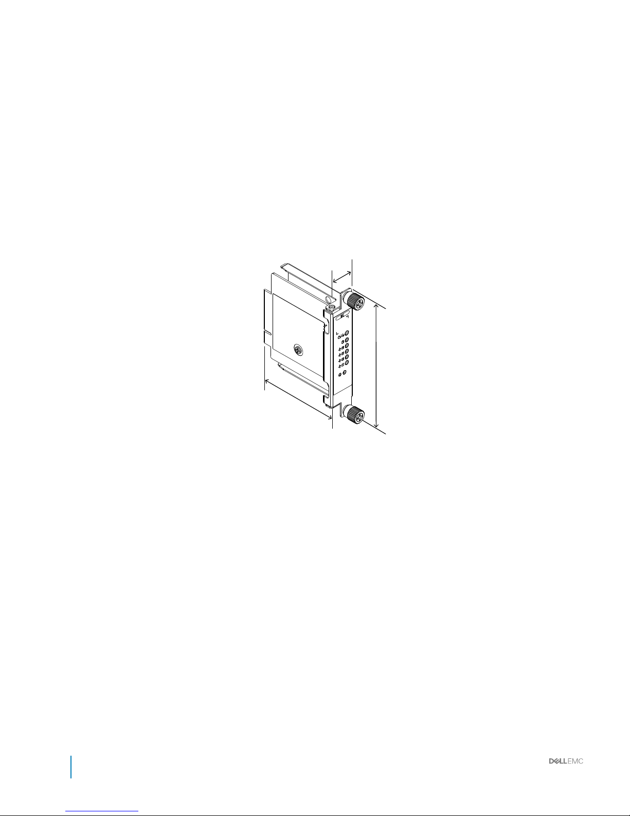
Block controller (BC) modules
Figure 22. BC module
36
Installation and Service Manual
Rear cabinet overview
Page 37
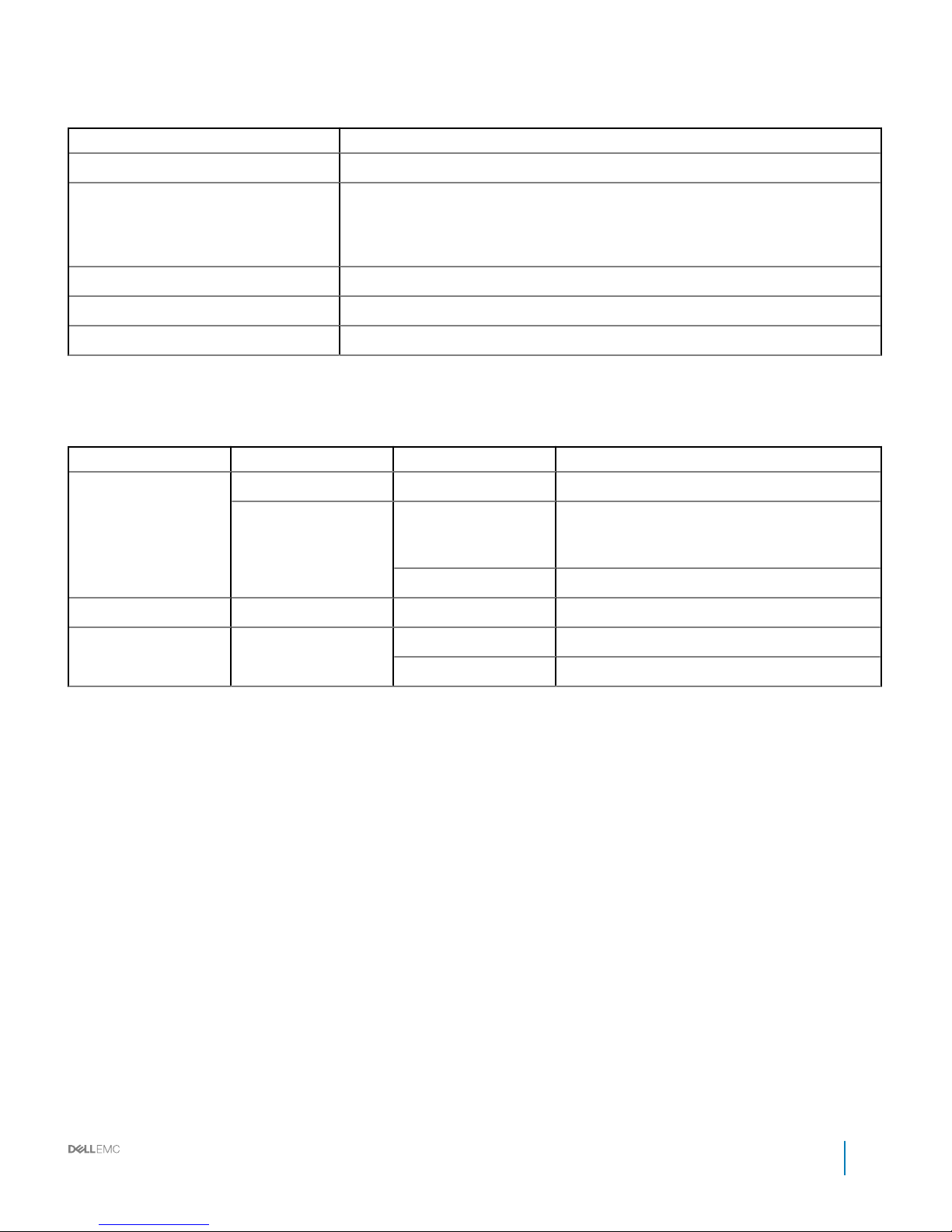
Table 10. BC module features
Item Description
Dimension (W x L x H) 120 mm x 24 mm x 88 mm (4.72 inch x 0.94 inch x 3.46 inch)
Connector
• 1 x PCIe x8 golden nger
• 1 x RS232
• 1 x JTAG
Switch 1 x Reset SW (Local)
Net weight 127.2 g (4.49 ounce)
Operating voltage/current 3.3 V, current 1 A
LED denition
Table 11. LED denition
LED Color Status Description
Power/Status Green On If there is no error
Amber On If there is an error from anyone of these: (Mac
address, Fan image, FPGA image, Mosfet, Ethernet
link, I2C, FPGA conguration).
Blinking Infrastructure mismatch
UID Blue On/O/Blinking Identify BC board location
Fan zone 1~2 Amber On Fan fail
O Normal work
Installation and Service Manual
Rear cabinet overview
37
Page 38
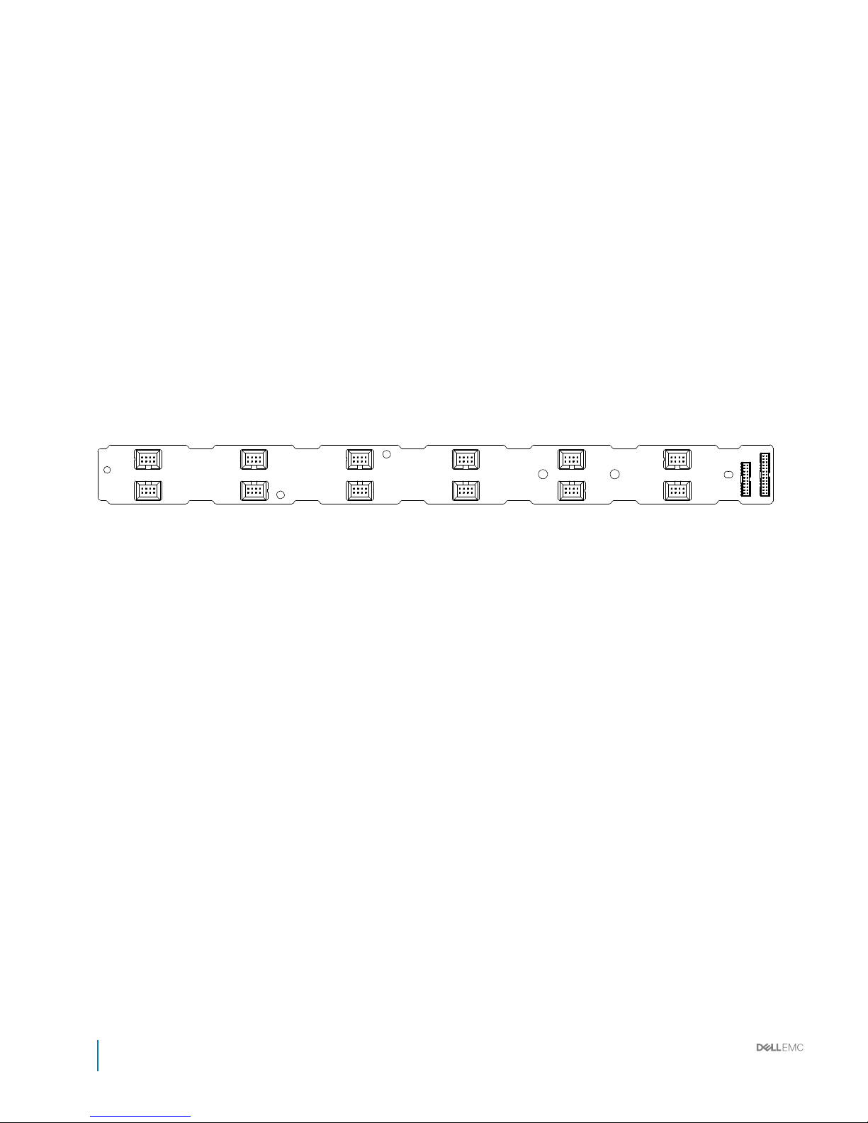
Fan power distribution boards (FPDB)
Figure 23. Fan power distribution board
38
Installation and Service Manual
Rear cabinet overview
Page 39
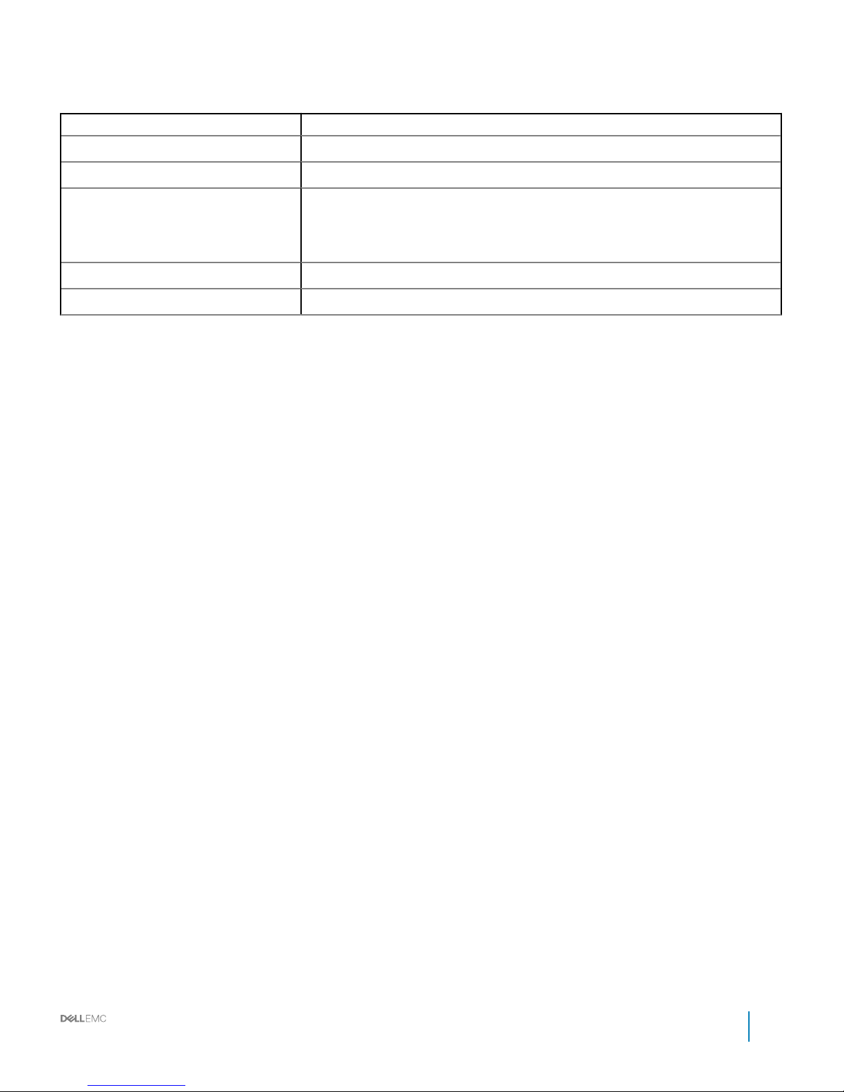
Table 12. Fan power distribution board features
Item Description
Board length 433 mm (17.05 inch)
Board width 38 mm (1.5 inch)
Connector
• 1x (2x10) connector
• 1x (2x13) connector
• 12 x (2x4) connector
Net weight 129.2 g (4.56 ounce)
Operating voltage/current 12 V, current 32 A
Installation and Service Manual
Rear cabinet overview
39
Page 40
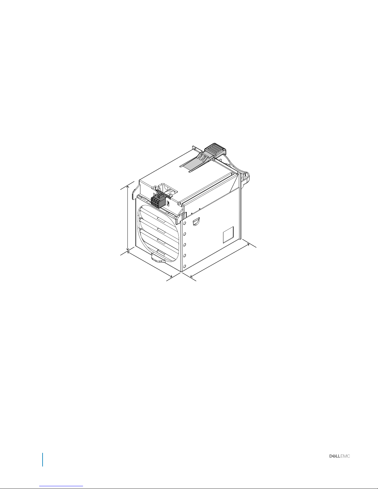
Fan modules
40 Installation and Service Manual
Rear cabinet overview
Page 41
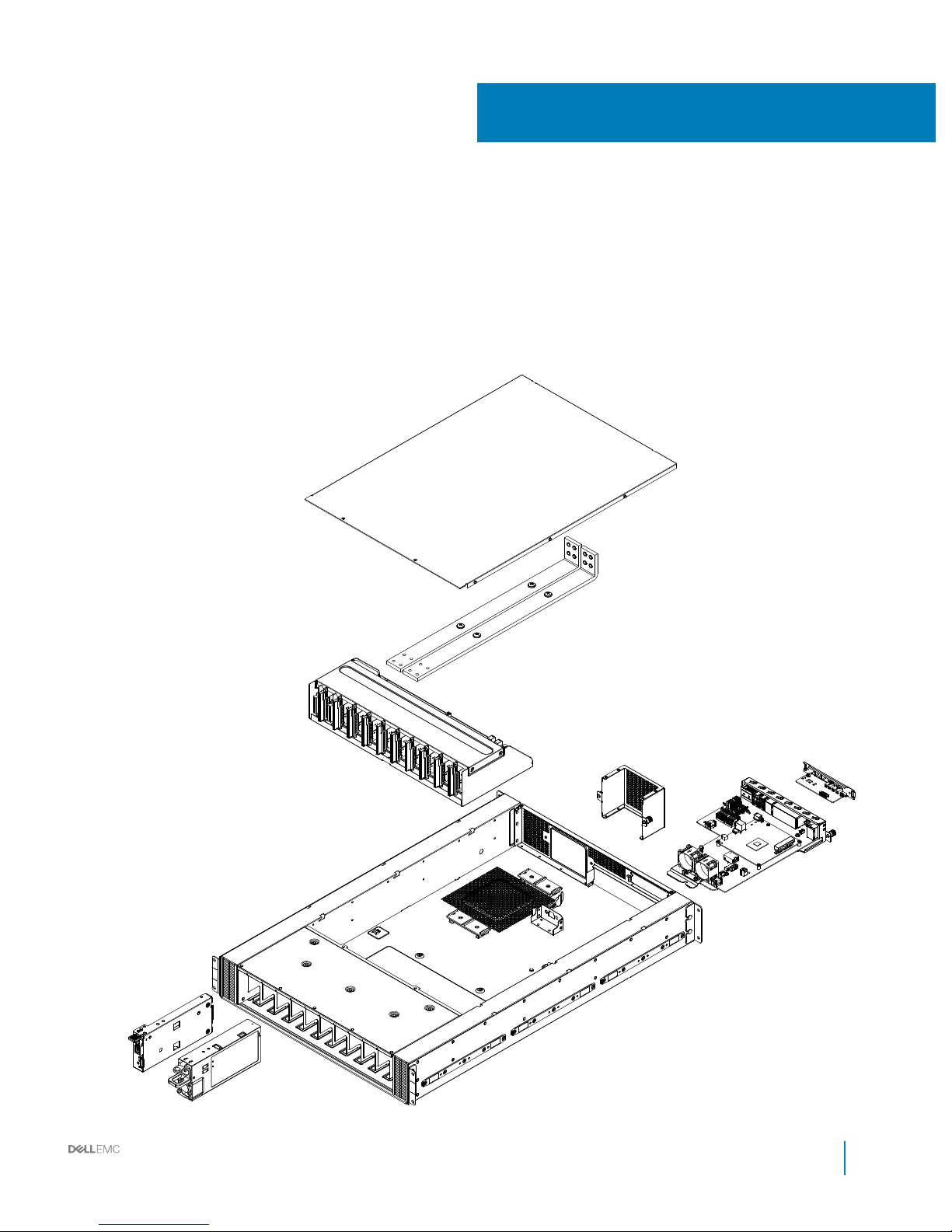
Power bay overview
4
Installation and Service Manual
Power bay overview
41
Page 42
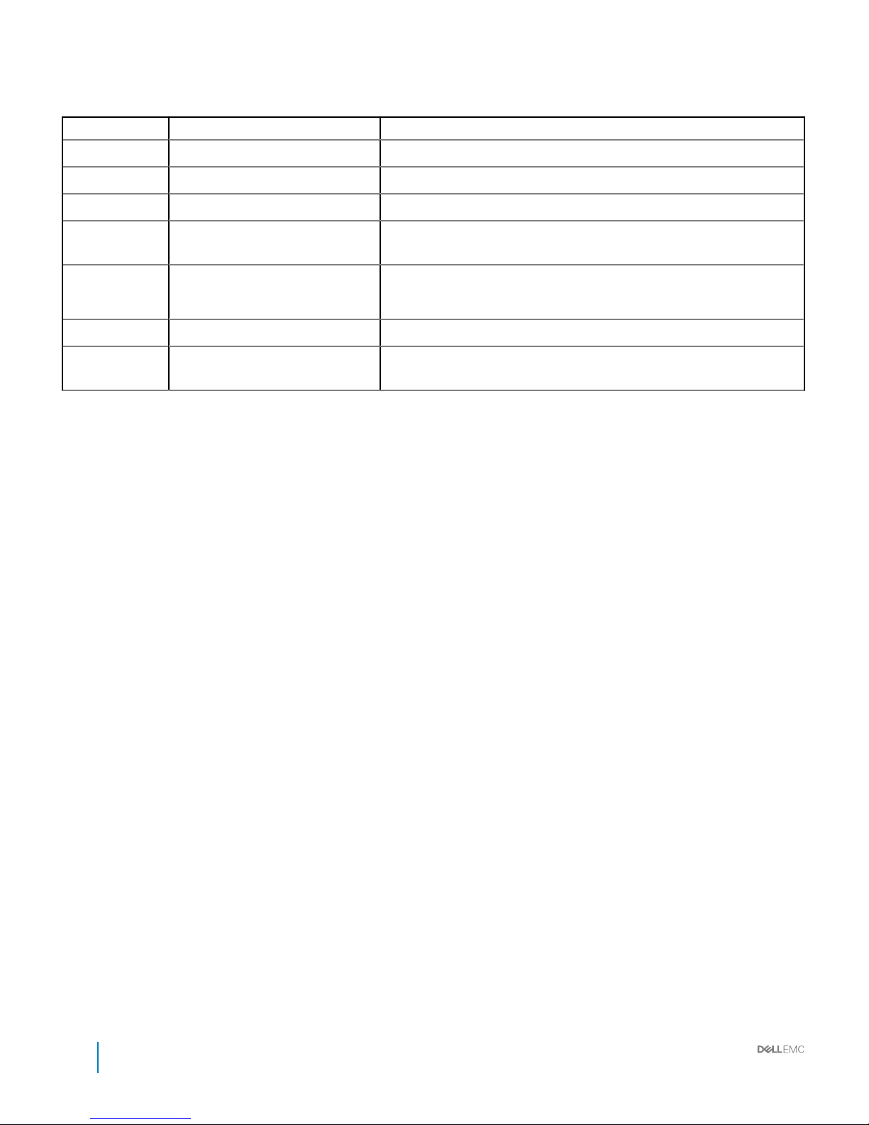
Table 13. Power bay features
No. Item Description
1 Top cover Top cover for the power bay chassis.
2 Bus Bar PB Bar strip to conduct electricity within the power bay.
3 PBPM Power bay power module regulates power control for the PSU.
4 Rear IO module Four RJ45 connectors, one 1x5 connector, one 1x6 connector and one 2x8
connector.
5 DSS 9000 rack manager module Includes rack manager board (RMB) and infrastructure module (IM).
MC and blocks of the IM are networked through a LAN.
6 Power supply unit (PSU) Ten hot-swappable power supply units.
7 Management controller module Monitoring through the on-board GbE to provide real-time two-way fan
speed and power status and operational event information.
Topics:
• Power bay specications
• Power bay unit
42
Installation and Service Manual
Power bay overview
Page 43
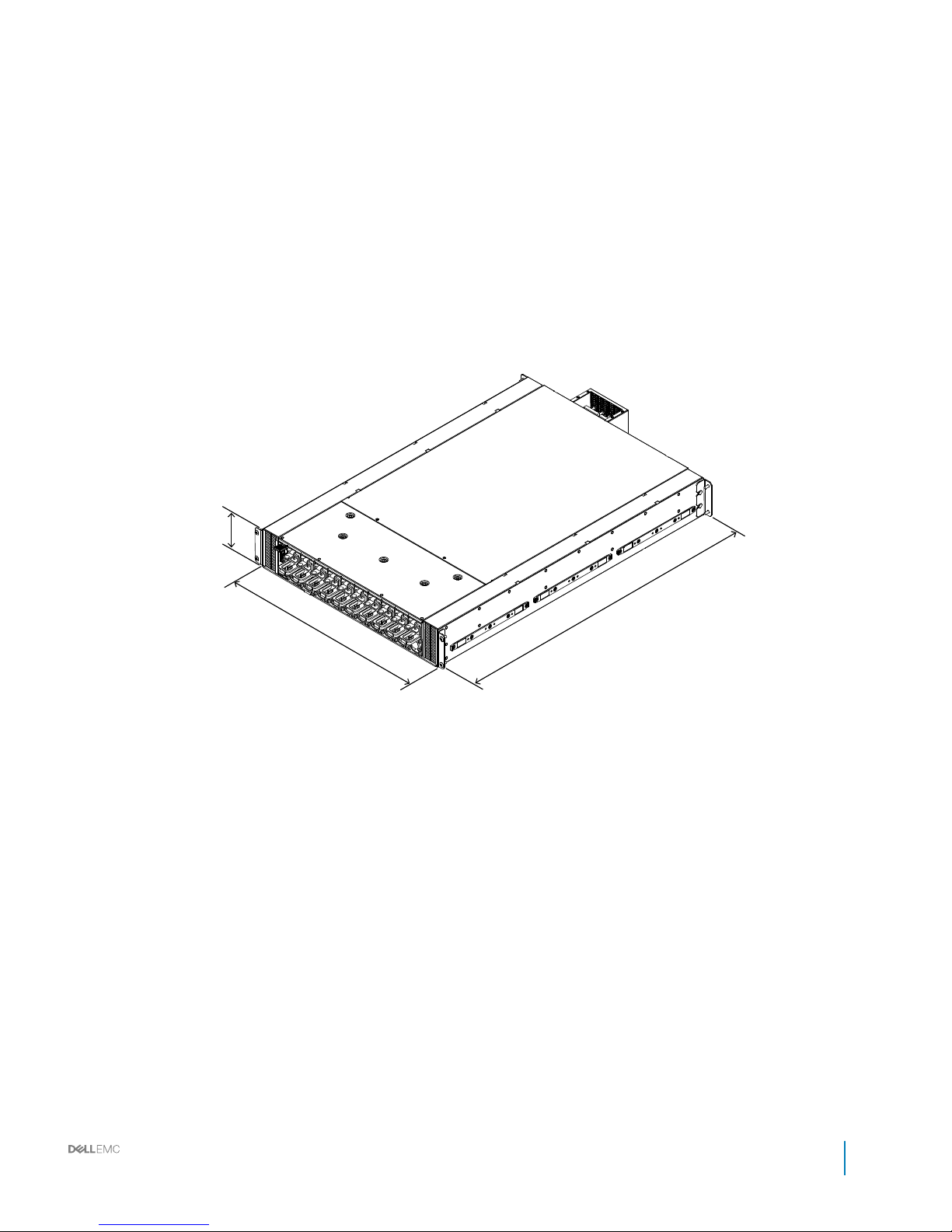
Power bay specications
Figure 25. Power bay
Installation and Service Manual
Power bay overview
43
Page 44
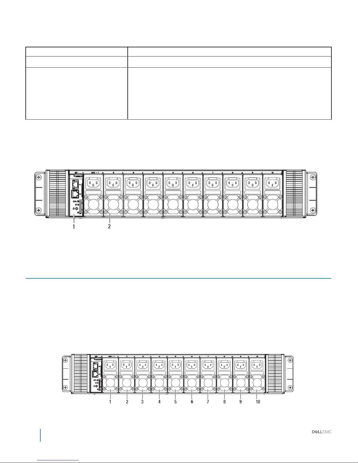
Table 14. Power bay features
Item Description
Dimensions (W x L x H) 537 mm x 800 mm x 98.6 mm (21.14 inch x 31.50 inch x 3.88 inch
Output
• Ripple/CS accuracy same as specied in PSU specications
• Static regulation/dynamic regulation at bus bar as denition location in PBPM
specications.
• On/O capacity through PMBus control
• Up to 10 kW (single PB with 5+5)
• Up to 18 kW (single PB with 9+1)
Power bay unit
The DSS 9000 leverages a power bay which houses up to ten AC power supply units (PSUs) to fully support the operational requirements
of the rack enclosure.
Figure 26. Power bay 1 MC + 10 PSU model (front view)
Table 15. Power bay 1 MC + 10 PSU model (front view)
No. Item Description
1 MC One management controller module
2 Power supply unit Ten hot-swappable power supply unit bays
Power bay allocation
When populating the PSU bays make sure to rst populate bays 1 to 6 then 7 to 10 as required. A minimum of six power supply units are
required to eectively sustain operations.
Figure 27. Power bay allocation
44
Installation and Service Manual
Power bay overview
Page 45

NOTE: To meet power requirements a minimum of six power supply units must be installed. Make sure to rst populate power
bays 1 to 6.
Installation and Service Manual
Power bay overview
45
Page 46
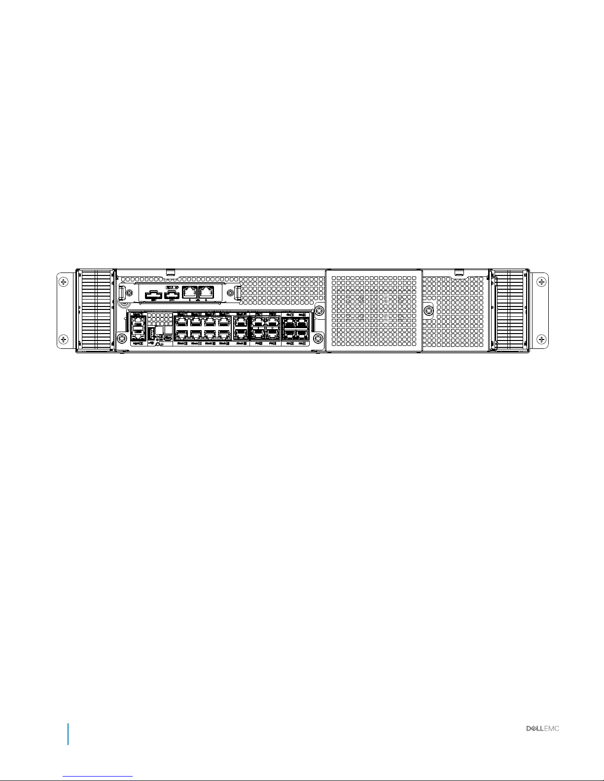
Rear view
46
Installation and Service Manual
Power bay overview
Page 47
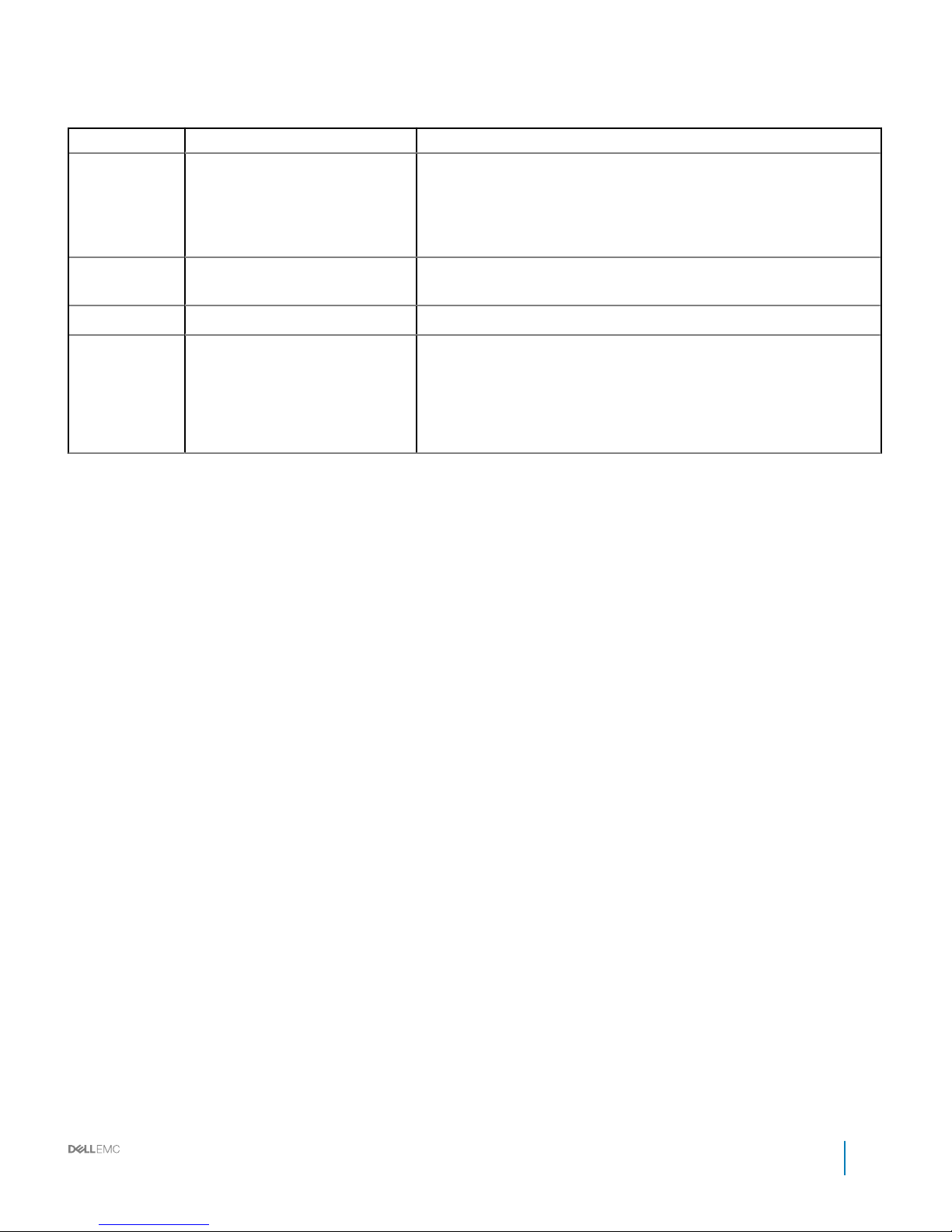
Table 16. Power bay overview (rear view)
No. Item Description
1 Rear IO
• RJ45 connectors (x 4)
• 1x5 connector (x 1)
• 1x6 connector (x 1)
• 2x8 connector (x 1)
2 Brush panel Allows cabling to be fed to or from the rear of the cabinet and prevents dust
ingress.
3 1U bus bar protector Cover to prevent contact with the bus bar and an electrical short circuit.
4 Infrastructure module
• Includes RJ45 ports
• UID, power/status LEDS
• Reset button
• ICs: MCU, Ethernet switch, SPI ROM, EEPROM, TMP sensor, and RS232
driver/receiver
Installation and Service Manual
Power bay overview
47
Page 48
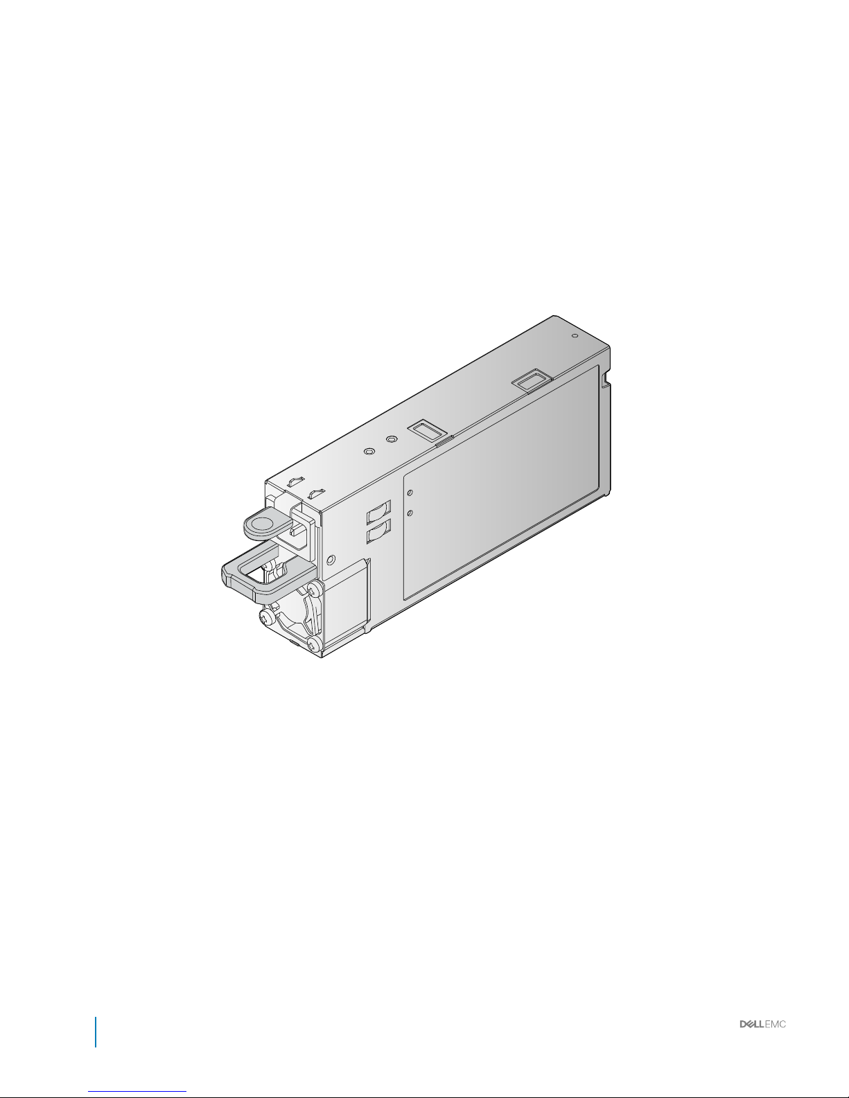
Power supply unit (PSU)
48
Installation and Service Manual
Power bay overview
Page 49
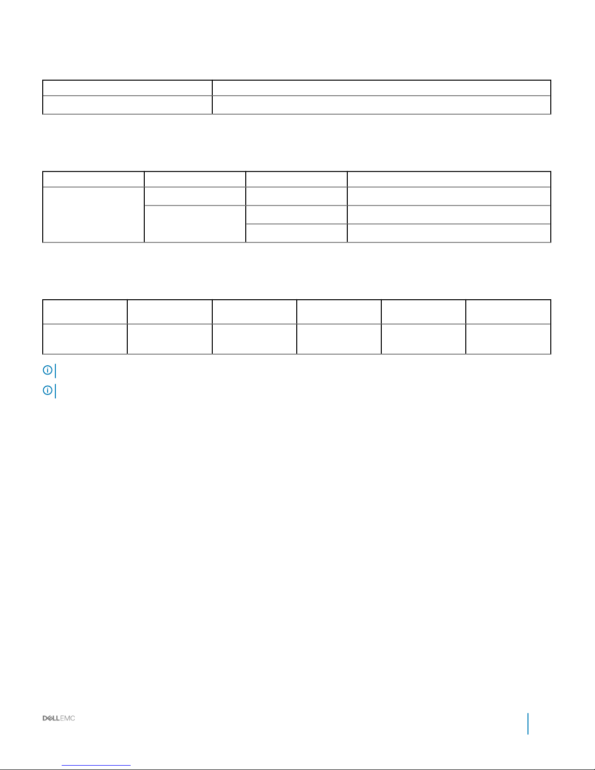
Table 17. Power supply unit (PSU)
Item Description
Operating Temperature 10°C to 50°C (50°F to 122°F)
LED denition
Table 18. LED
LED Color Status Description
PSU LED Green Solid OK
Amber Blinking Fault
O O
PSU specications
Table 19. PSU specications
PSU wattage Class Heat dissipation
(maximum)
Frequency Voltage Maximum input
current
2000 W AC Platinum 675.37 BTU/hr 50/60 Hz 100–240 V AC,
autoranging
11.5 A
NOTE: Heat dissipation is calculated using the PSU wattage rating.
NOTE: This system is also designed to connect to the IT power systems with a phase to phase voltage not exceeding 230 V.
Installation and Service Manual
Power bay overview
49
Page 50
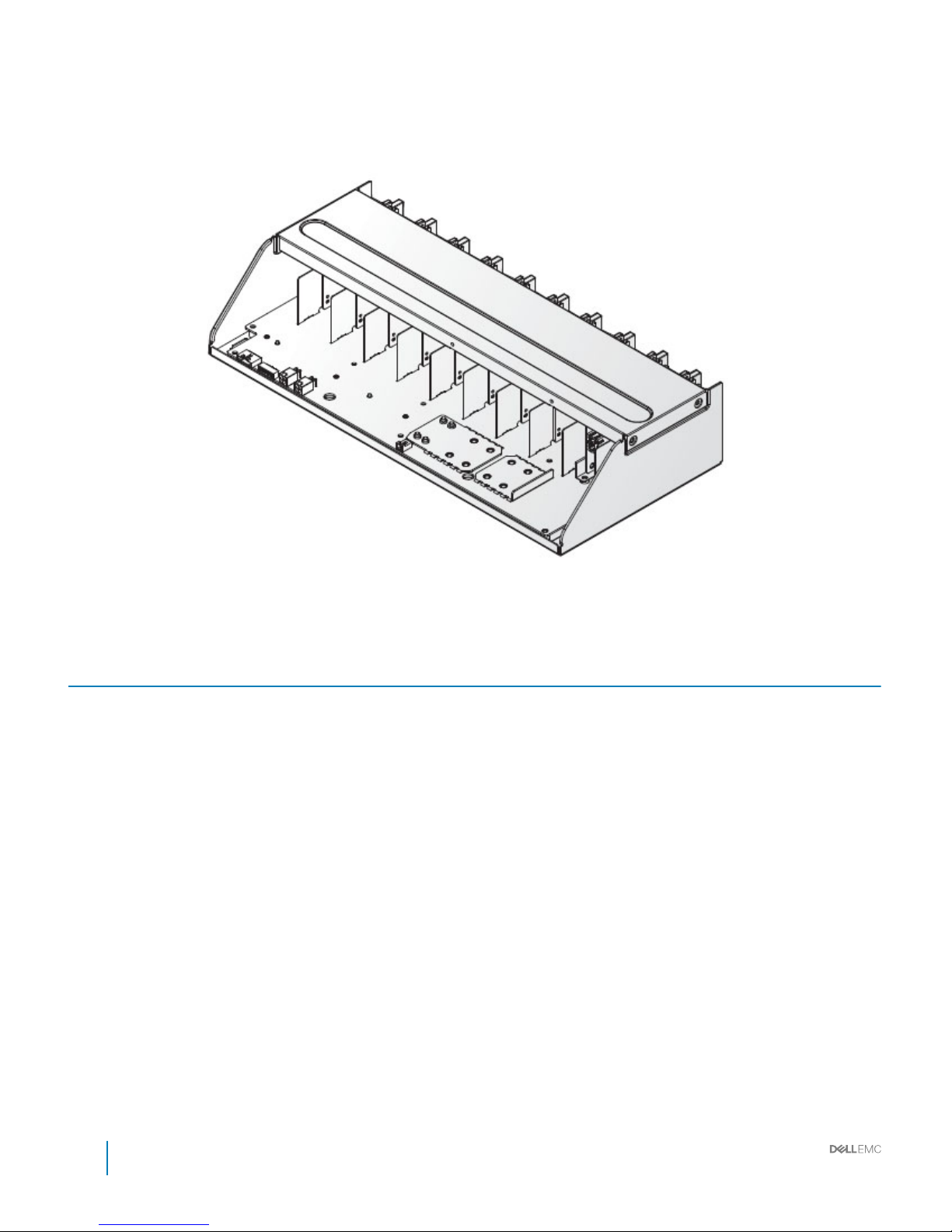
Power bay power module (PBPM)
Figure 30. Power bay power module (PBPM)
Table 20. Power bay power module (PBPM)
Item Description
• Supports multiple (max. 10) PSUs, each up to 2000 W PSU
• Supports up to two management controller cartridges
50 Installation and Service Manual
Power bay overview
Page 51
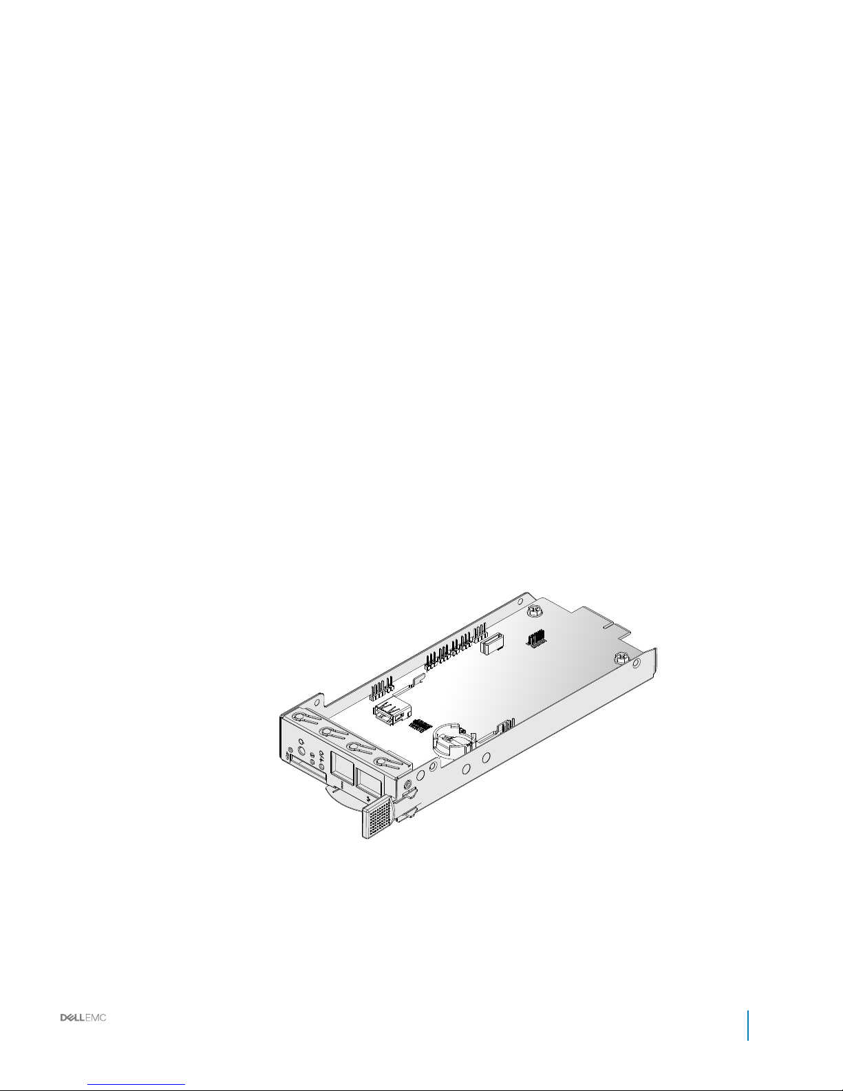
Management controller (MC) module
Installation and Service Manual
Power bay overview
51
Page 52
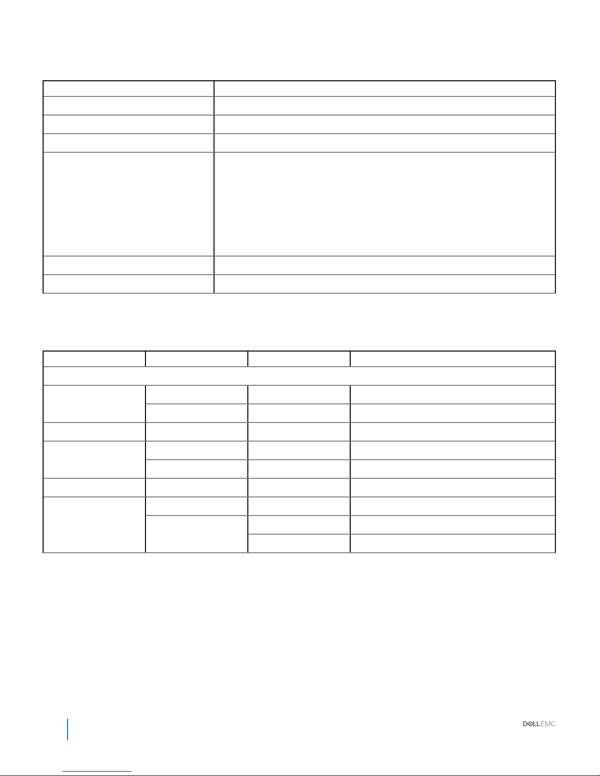
Table 21. Management controller
Item Description
Board length 204.1 mm (8.03 inch)
Board width 82 mm (3.22 inch)
Net Weight 79 g (2.78 ounce.)
Connector
• 1 x PCIe x4 Gold-nger
• 1 x RJ45
• 1 x Serial RJ45
• 1 x SD socket
• 1 x USB
• 1 x JTAG
• 1 x Battery holder
Switch 1 x Power Button
Operating voltage/current 12 V, current 1.3 A
LED denition
Table 22. LED
LED Color Status Description
LAN port
Status Green On 1G LAN speed
Amber On 10M/100M LAN speed
Activity Green Blinking Trac access
Power/Status Green On Power on
Amber On Power on fail
UID Blue On/O/Blinking Identify MC board location
Error Green On If there is no error
Amber Blinking Infrastructure mismatch
On Link between MC and IM is Absent
52 Installation and Service Manual
Power bay overview
Page 53
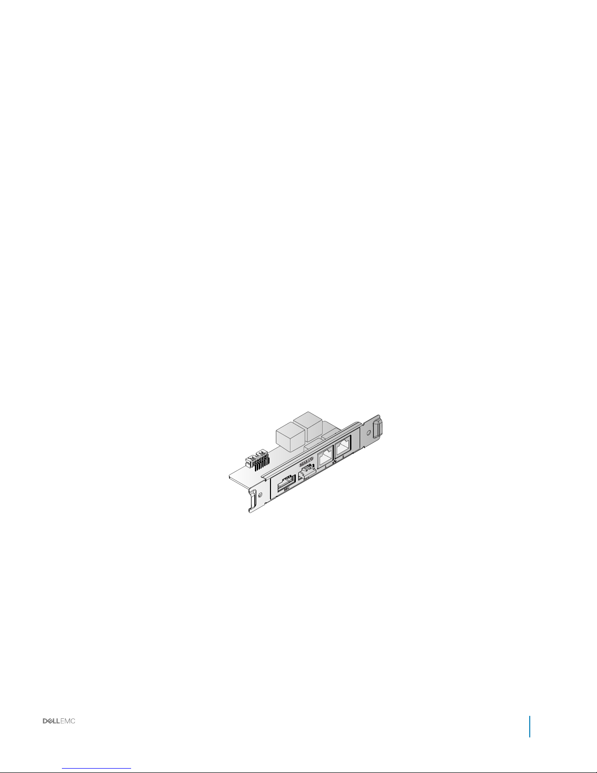
Rear IO module
Installation and Service Manual
Power bay overview
53
Page 54
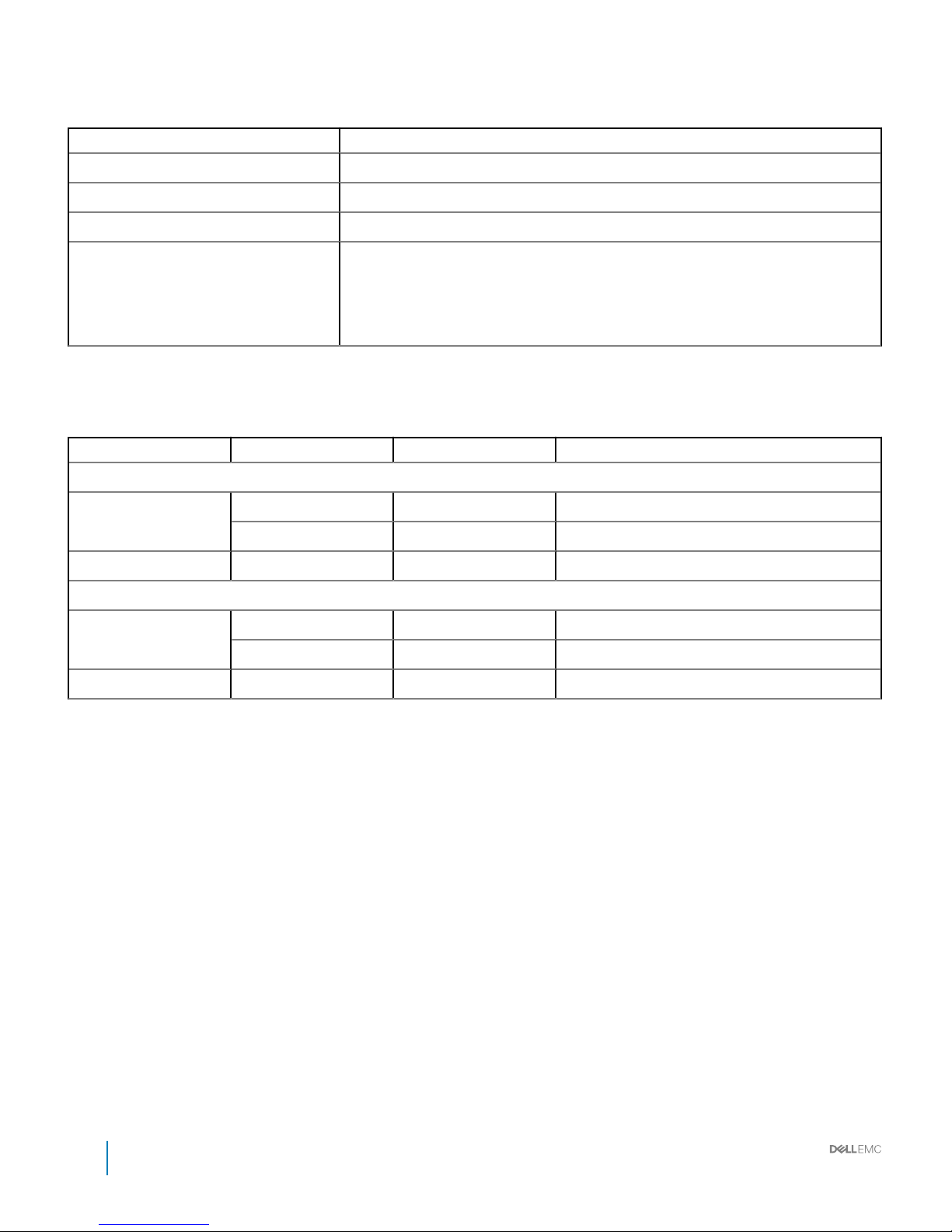
Table 23. Rear IO module
Item Description
Board length 105 mm (4.13 inch)
Board width 40 mm (1.57 inch)
Net Weight 62.2 g (2.19 ounce)
Connector
• 4 x RJ45 connector
• 1 x (1x5) connector
• 1 x (1x6) connector
• 1 x (2x8) connector
LED denition
Table 24. LED
LED Color Status Description
LAN1 port
Status Green On 1G LAN speed
Amber On 10M/100M LAN speed
Activity Green Blinking Trac access
LAN1 port
Status Green On 10M/100M LAN speed
Amber On 1G LAN speed
Activity Green Blinking Trac access
54 Installation and Service Manual
Power bay overview
Page 55
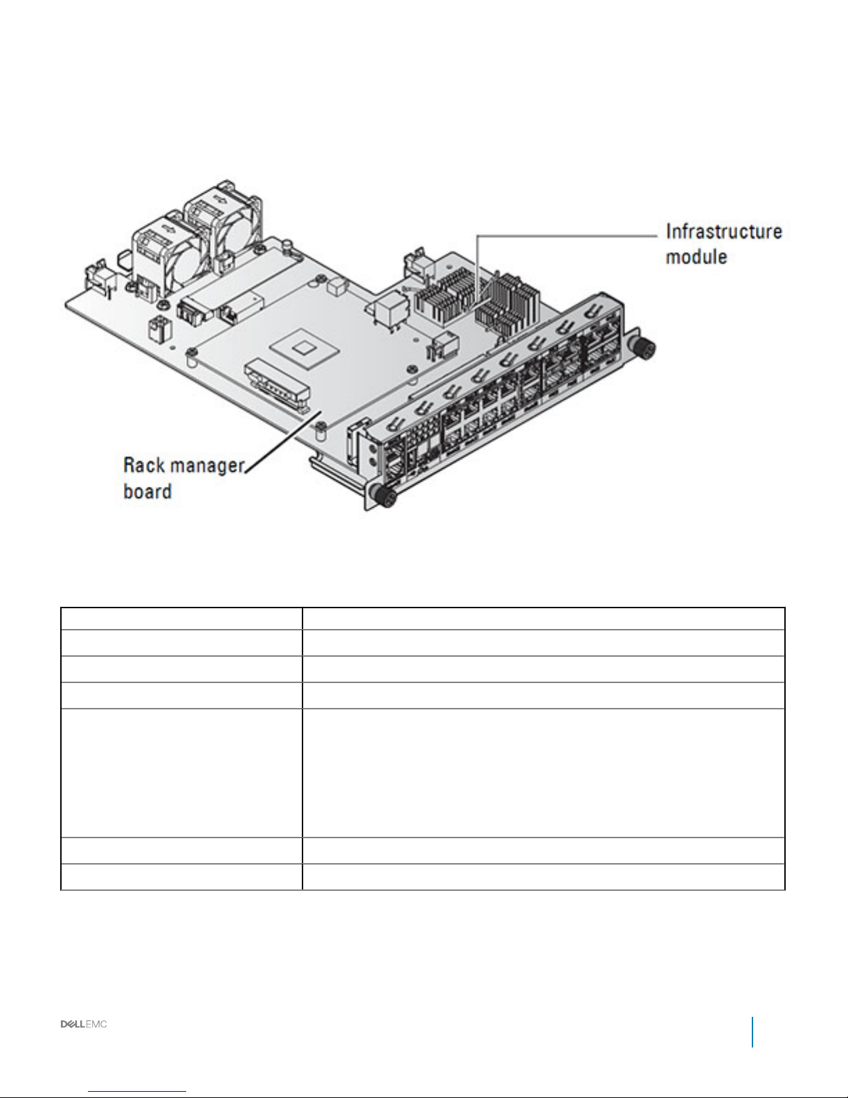
DSS 9000 rack manager module
Figure 33. DSS 9000 rack manager module
Table 25. DSS 9000 rack manager module features
Item Description
Board length 323.25 mm (12.73 inch)
Board width 242.3 mm (9.54 inch)
Net Weight 1,050 g (37.03 ounce)
Connector
• 2 x 8-port RJ45
• 1 x 2-port RJ45
• 1 x (2x2) Power connector
• 1 x USB
• 1 x (1x5) connector
• 1 x Micro USB
Switch 1 x Reset Button
Operating voltage/current 12 V, current 2 A
Infrastructure module LED denition
Installation and Service Manual
Power bay overview
55
Page 56
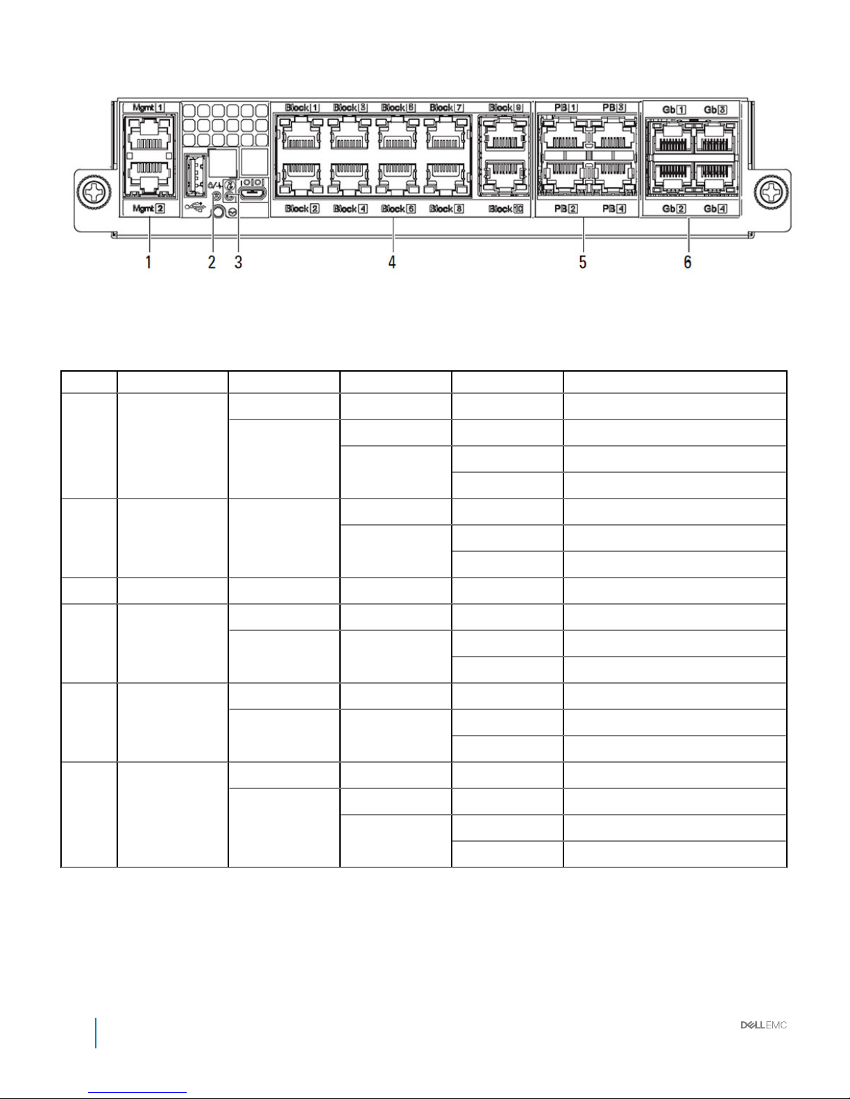
Figure 34. LED denition
Table 26. LED denition
Item Port LED Color Status Description
1 Mgmt Right LED Green Blinking Active
Left LED Green On Link speed: 1Gb
Yellow On Link speed: Others
O No link
2 Power/Status Green On Fault not detected
Amber On Fault detected: Mac address, I2C.
Blinking Infrastructure mismatch or fan fault
3 UID Blue On/O/Blinking Identify IM board location
4 Block (1-10) Right LED Green Blinking Active
Left LED Green On Link speed: 1Gb
O No link
5 PB (1-4) Right LED Green Blinking Active
Left LED Yellow On Link speed: 100Mb
O Link speed: 10Mb or no link
6 Gb (1-4) Right LED Green Blinking Active
Left LED Green On Link speed: 1Gb
Yellow On Link speed: Other
O No link
56 Installation and Service Manual
Power bay overview
Page 57
Bus bar overview
The DSS 9000 rack enclosure includes bus bar to the following areas:
• Rack level
• Block level
• Power bay level
Topics:
• Rack level bus bar
• Block level bus bar
• Power bay level bus bars
Rack level bus bar
Bus bar top
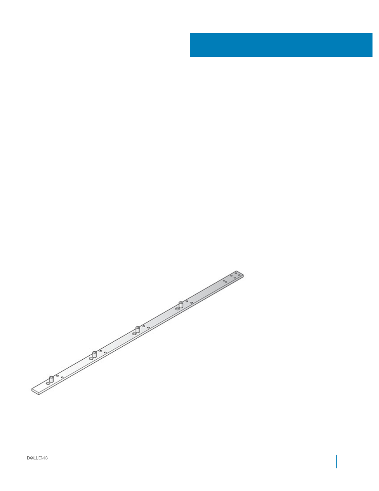
The top of the rack includes two bus bars, positive and negative. The bus bars are coupled to the middle bus bars for upward distribution of
the system’s power.
Figure 35. Bus bar top-P (positive, red)
5
Installation and Service Manual
Bus bar overview
57
Page 58
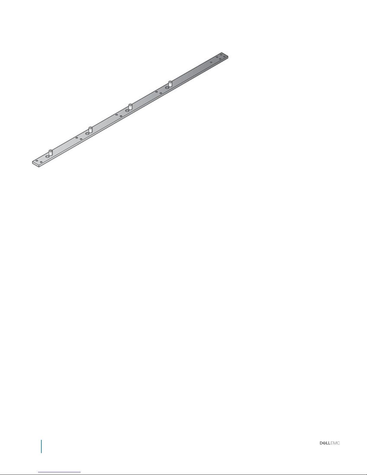
Figure 36. Bus bar top-N (negative, black)
Bus bar middle
The middle of the rack includes two bus bars, positive and negative. The bus bars couple the power block and the top bus bars for upward
distribution of the system’s power.
58
Installation and Service Manual
Bus bar overview
Page 59
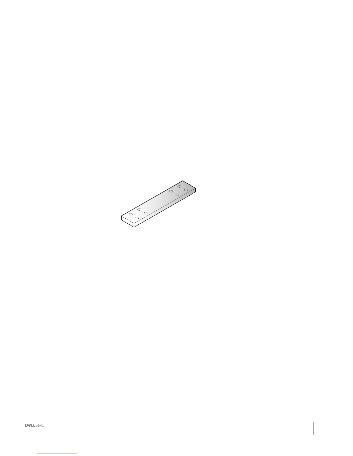
Figure 37. Bus bar middle-P (positive, red)
Installation and Service Manual
Bus bar overview
59
Page 60
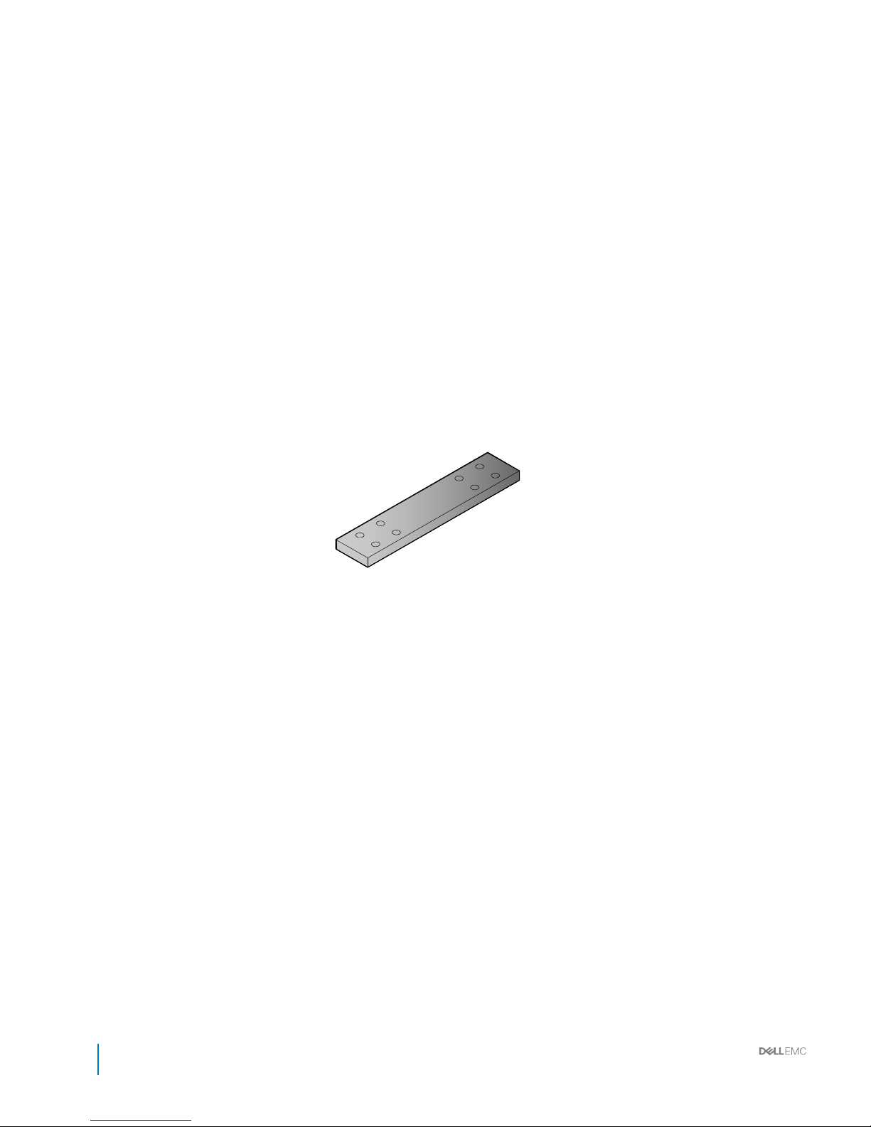
Figure 38. Bus bar middle-N (negative, black)
60
Installation and Service Manual
Bus bar overview
Page 61
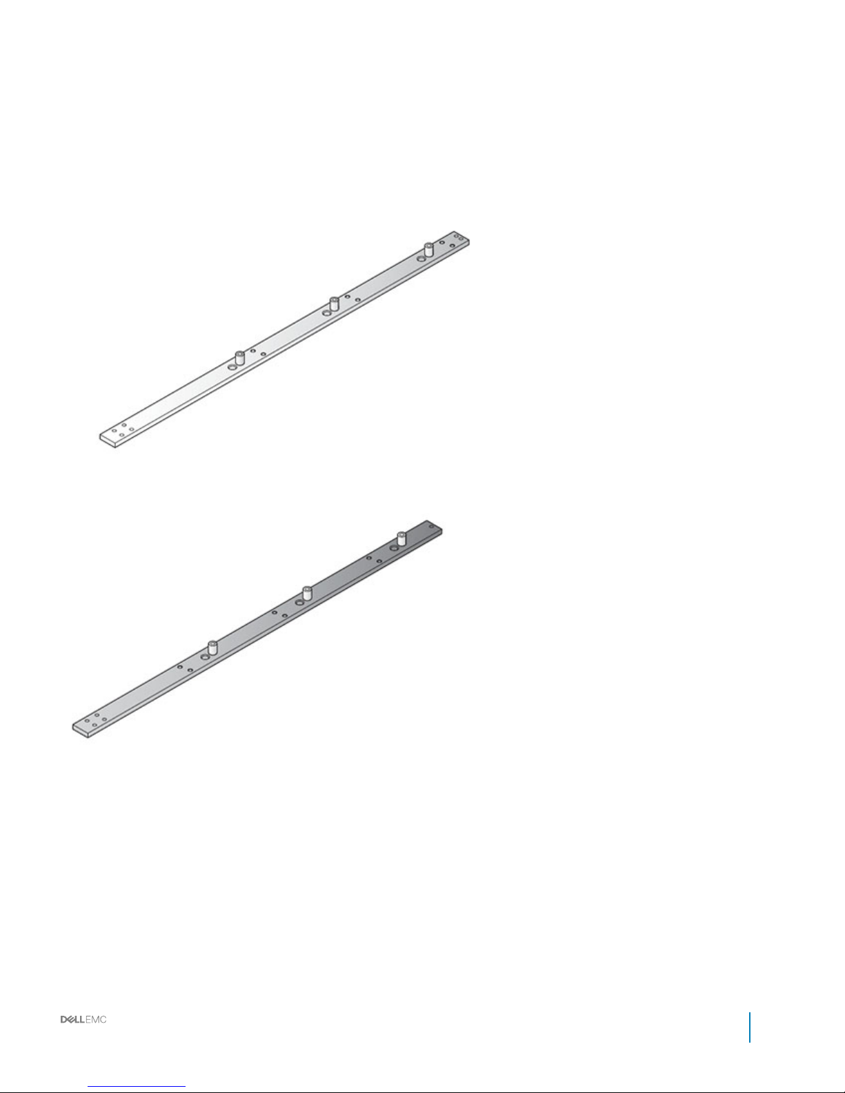
Bus bar bottom
The bottom of the rack includes two bus bars, positive and negative. The bus bars are coupled to the middle bus bars for downward
distribution of the system’s power.
Figure 39. Bus bar bottom-P (positive, red)
Figure 40. Bus bar bottom-N (negative, black)
Block level bus bar
The following cross bus bar types are specic for the 6GU block.
Installation and Service Manual
Bus bar overview
61
Page 62
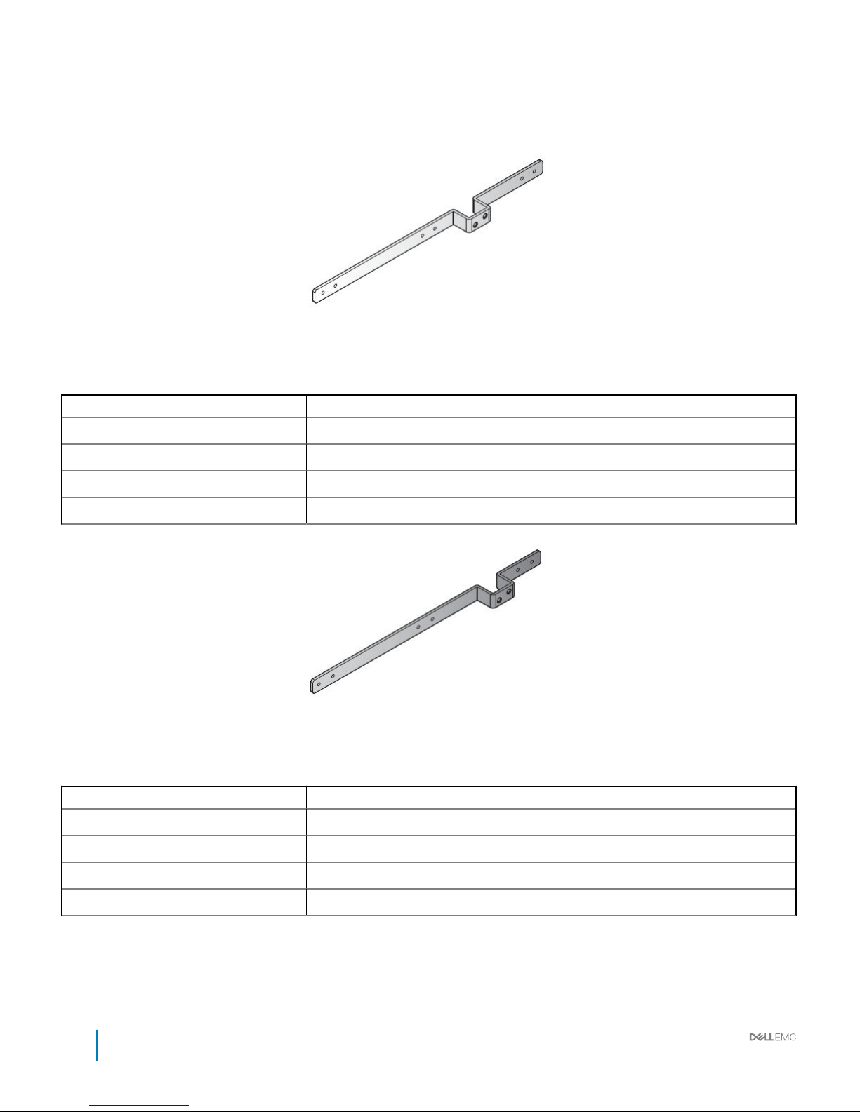
One third-width cross bus bar block
Figure 41. One third-width cross bus bar block-P (positive, red)
Table 27. Third width cross bus bar block-P (positive, red)
Item Description
Length 334.4 mm (13.17 inch)
Width 20 mm (0.79 inch)
Height 34 mm (1.34 inch)
Thickness 4 mm (0.16 inch)
Figure 42. One third-width cross bus bar block-N (negative, black)
Table 28. One third-width cross bus bar block-N (negative, black)
Item Description
Length 334.4 mm (13.17 inch)
Width 20 mm (0.79 inch)
Height 34 mm (1.34 inch)
Thickness 4 mm (0.16 inch)
62 Installation and Service Manual
Bus bar overview
Page 63
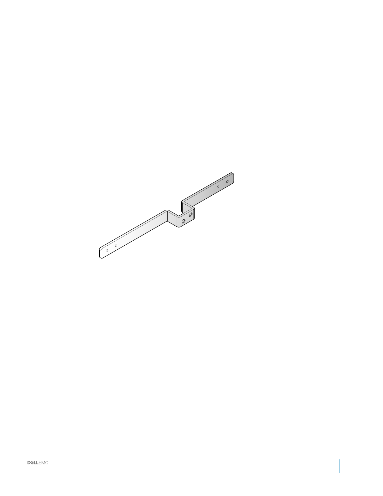
Half-width/full-width cross bus bar block
Installation and Service Manual
Bus bar overview
63
Page 64
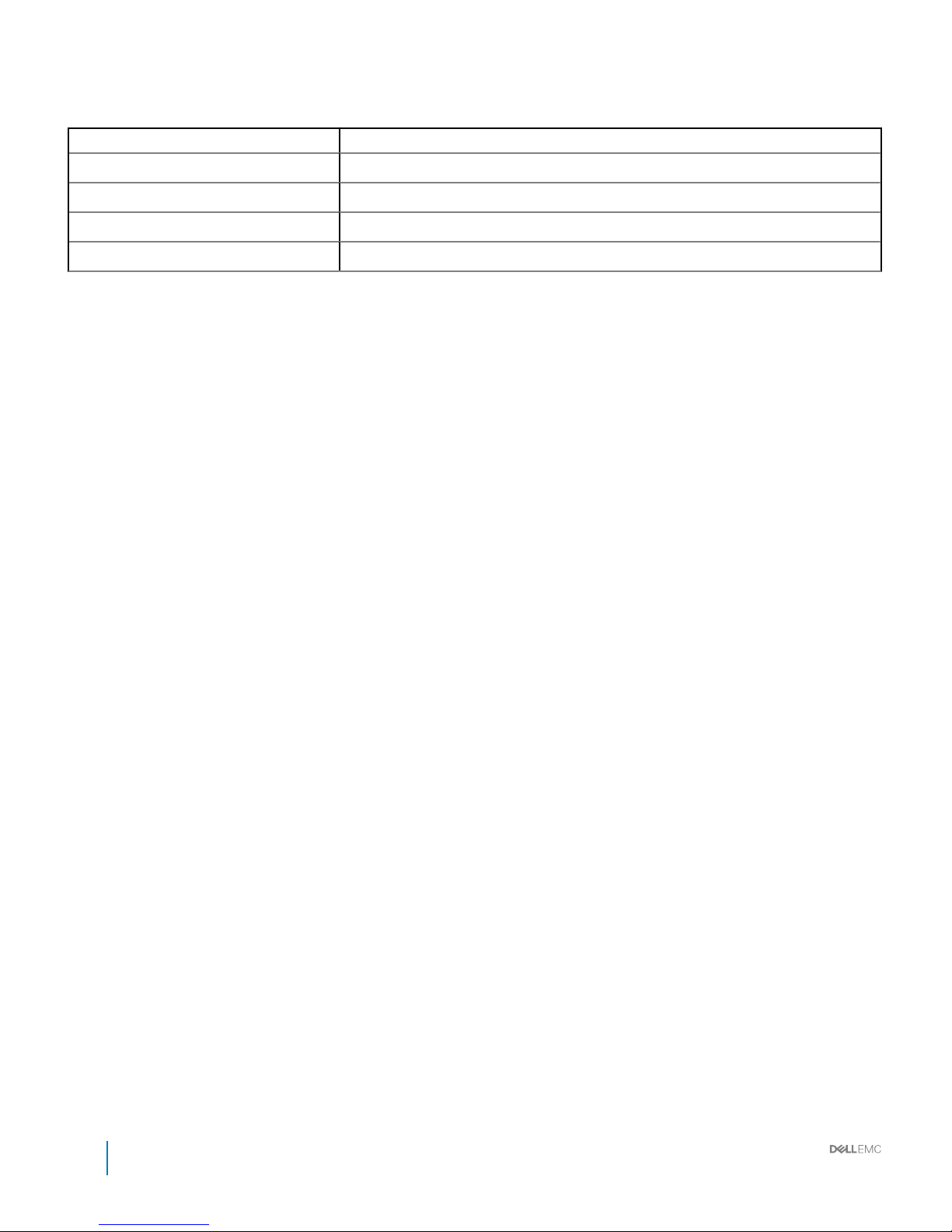
Table 29. Half-width/full-width cross bus bar block-P (positive, red)
Item Description
Length 334.4 mm (13.17 inch)
Width 20 mm (0.79 inch)
Height 34 mm (1.34 inch)
Thickness 4 mm (0.16 inch)
64 Installation and Service Manual
Bus bar overview
Page 65
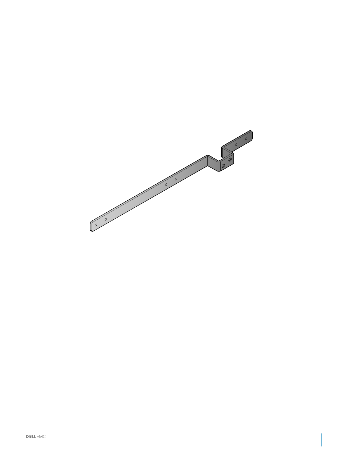
Figure 44. Half-width/full-width cross bus bar block-N (negative, black)
Installation and Service Manual
Bus bar overview
65
Page 66
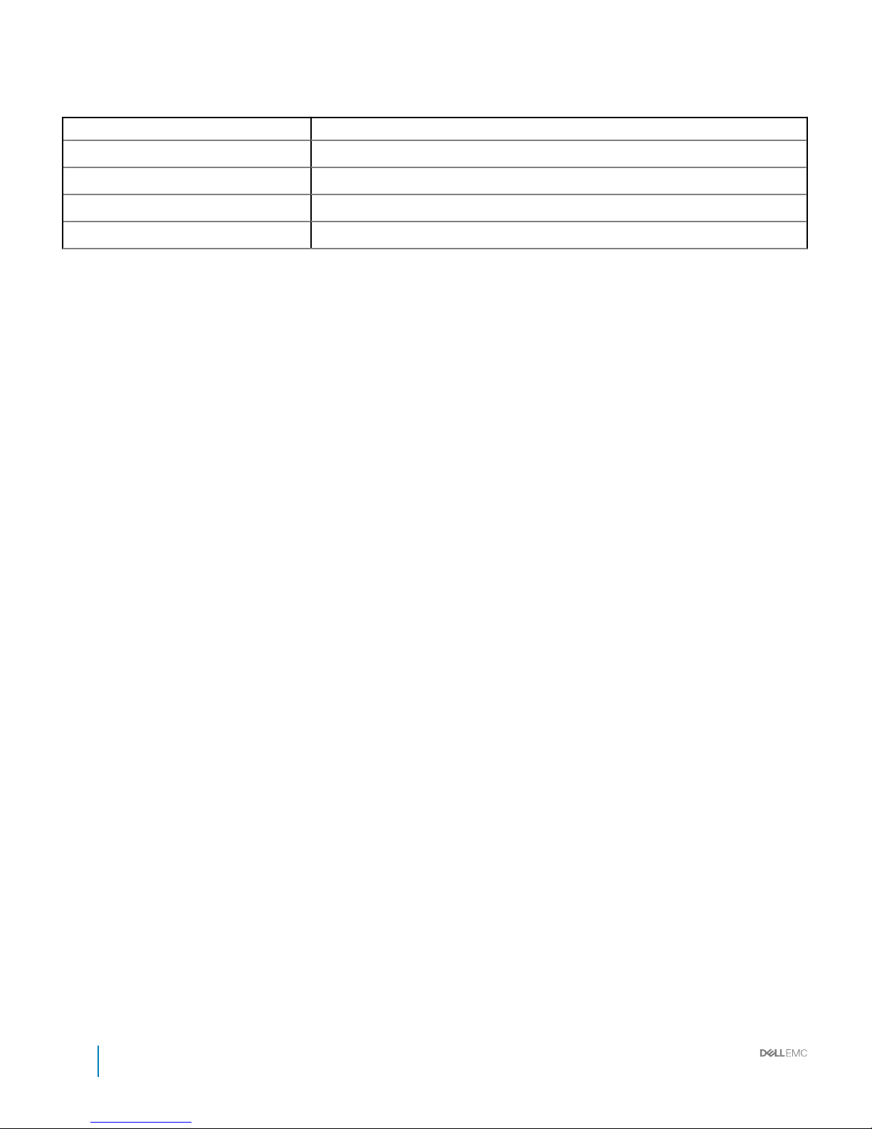
Table 30. Half-width/full-width cross bus bar block-N (negative, black)
Item Description
Length 334.4 mm (13.17 inch)
Width 20 mm (0.79 inch)
Height 34 mm (1.34 inch)
Thickness 4 mm (0.16 inch)
66 Installation and Service Manual
Bus bar overview
Page 67
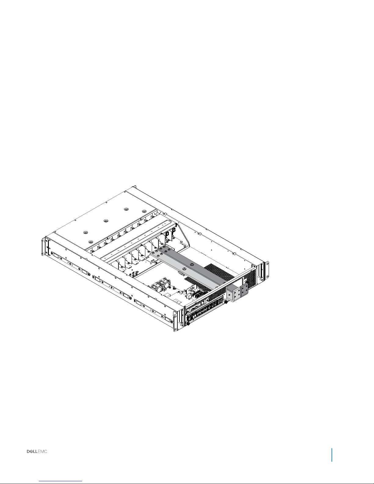
Power bay level bus bars
Figure 45. Power bay level bus bar
Installation and Service Manual
Bus bar overview
67
Page 68
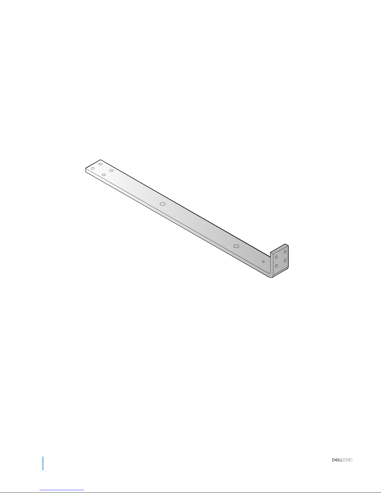
Bus bar-PB
68
Installation and Service Manual
Bus bar overview
Page 69
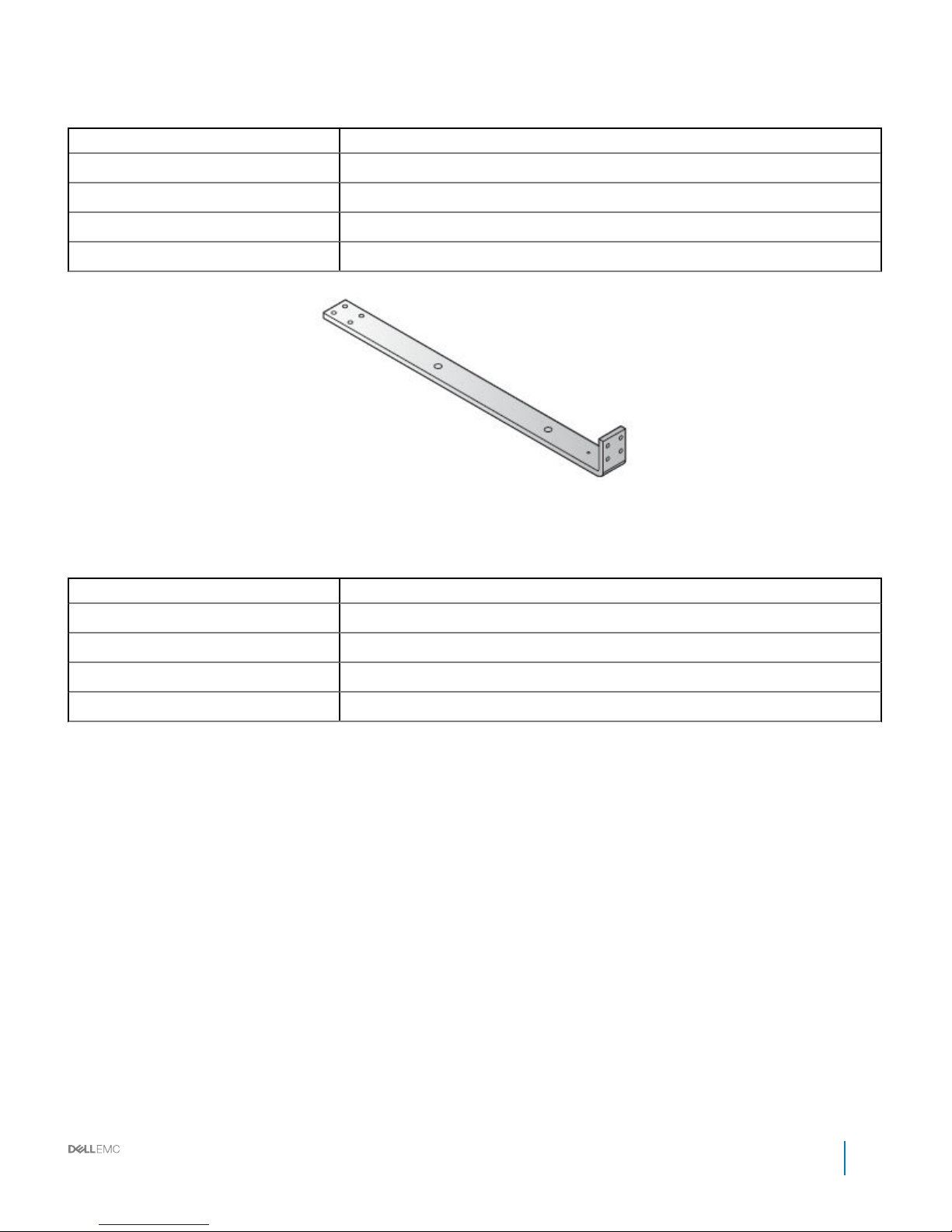
Table 31. Bus bar-PB-P (positive, red)
Item Description
Length 507.7 mm (19.99 inch)
Width 40 mm (1.57 inch)
Height 58.8 mm (2.31 inch)
Thickness 8 mm (0.31 inch)
Figure 47. Bus bar-PB-N (negative, black)
Table 32. Bus bar-PB-N (negative, black)
Item Description
Length 507.7 mm (19.99 inch)
Width 40 mm (1.57 inch)
Height 58.8 mm (2.31 inch)
Thickness 8 mm (0.31 inch)
Installation and Service Manual
Bus bar overview
69
Page 70

Installing and removing system components
Topics:
• Safety instructions
• Recommended tools
• Service parts list
• Servers
• Hard disk drive (HDD) trays
• Power supply units (PSU)
• Fan modules
• Fan blocks
• Fan power distribution boards (FPDB)
• Block Controller Distribution Board (BCDB)
• Installing BCDB
• Block controllers (BC)
• Management controllers (MC)
• Rack manager board (RMB) and infrastructure module (IM)
• Rear IO modules
• Power interface board (PIB)
Safety instructions
CAUTION
: Many repairs may only be done by a certied service technician. You should only perform troubleshooting and simple
repairs as authorized in your product documentation, or as directed by the online or telephone service and support team.
Damage due to servicing that is not authorized is not covered by warranty. Read and follow the safety instructions that are
shipped with your product.
System components and electronic circuit boards can be damaged by discharges of static electricity. Working on systems that are still
connected to a power supply can be extremely dangerous. To avoid injury to yourself or damage to system, follow these guidelines:
• Wear a grounded wrist strap when working inside the system chassis.
• Handle electronic circuit boards only by the edges, ensuring not to touch the components on the board. Do not ex or stress the circuit
board.
• Store all components inside a static-proof packaging until you are ready to use the components for installation.
Recommended tools
• Phillips screwdriver #2
Service parts list
• DSS 9000 System
• Fan module
6
70 Installation and Service Manual
Installing and removing system components
Page 71

• Power
• PSU
• PBPM
• Mechanical
• PSU blank
• Third width server blank
• Half width server blank
• Full width server blank
• PCBA module
• MC
• MC cover
• DSS 9000 rack manager module
• Infrastructure module
• Rear I/O
• BC
Servers
Removing one third-width server
Prerequisite
1 Ensure that you read the Safety instructions.
Steps
1 Press the release latches on the side of the server.
2 Slide the server out of the block.
Installation and Service Manual
Installing and removing system components
71
Page 72
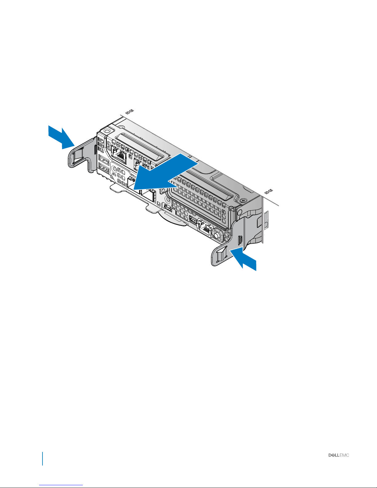
Figure 48. Removing the one third-width server
72
Installation and Service Manual
Installing and removing system components
Page 73

Installing one third-width server
1 Align the server with the bay, and insert the server into the block.
2 Slide the server in until it is fully seated in the block.
The server locks in place after it is properly seated.
Installation and Service Manual
Installing and removing system components
73
Page 74
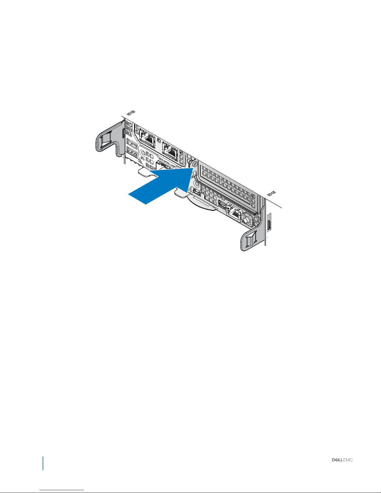
Figure 49. Installing the one third-width server
74
Installation and Service Manual
Installing and removing system components
Page 75

Removing half-width server
Prerequisite
1 Ensure that you read the Safety instructions.
Steps
1 Press the release latches on the side of the server.
2 Slide the server out of the block.
Installation and Service Manual
Installing and removing system components
75
Page 76
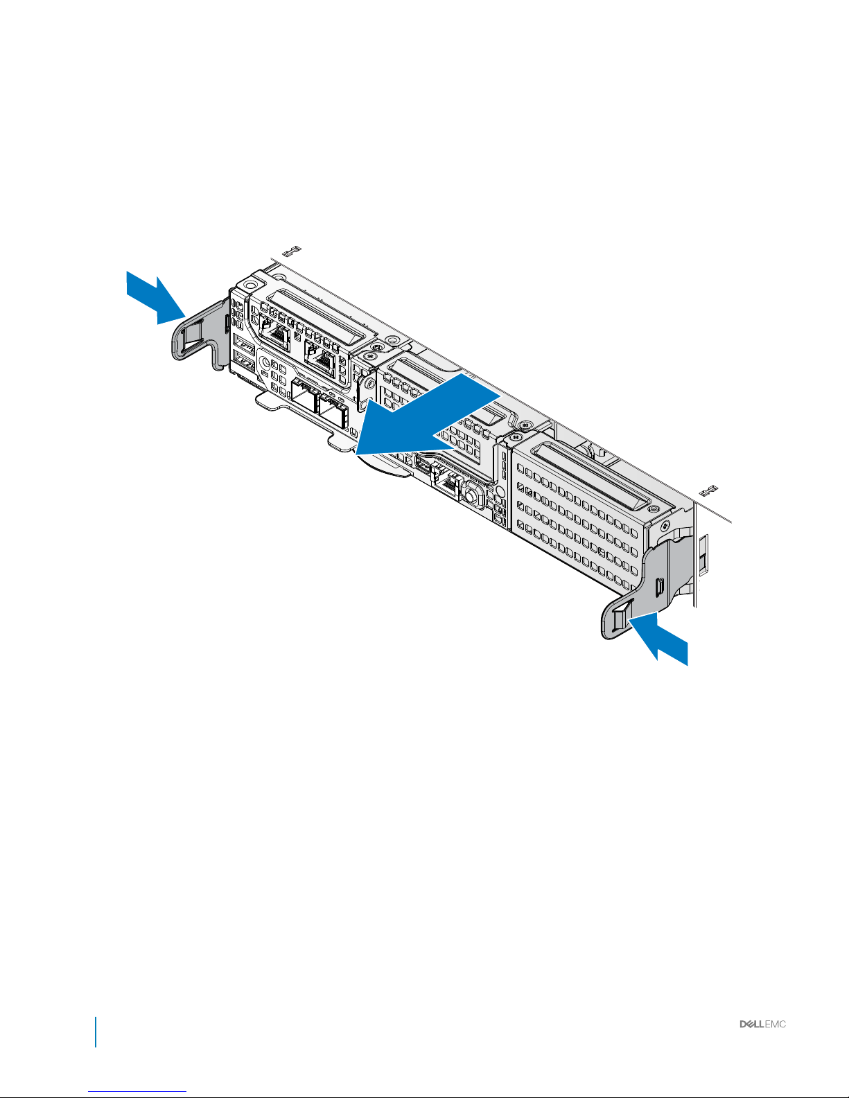
Figure 50. Removing the half-width server
76
Installation and Service Manual
Installing and removing system components
Page 77

Installing half-width server
1 Align the server with the bay, and insert the server into the block.
2 Slide the server in until it is fully seated in the block.
The server locks in place after it is properly seated.
Installation and Service Manual
Installing and removing system components
77
Page 78
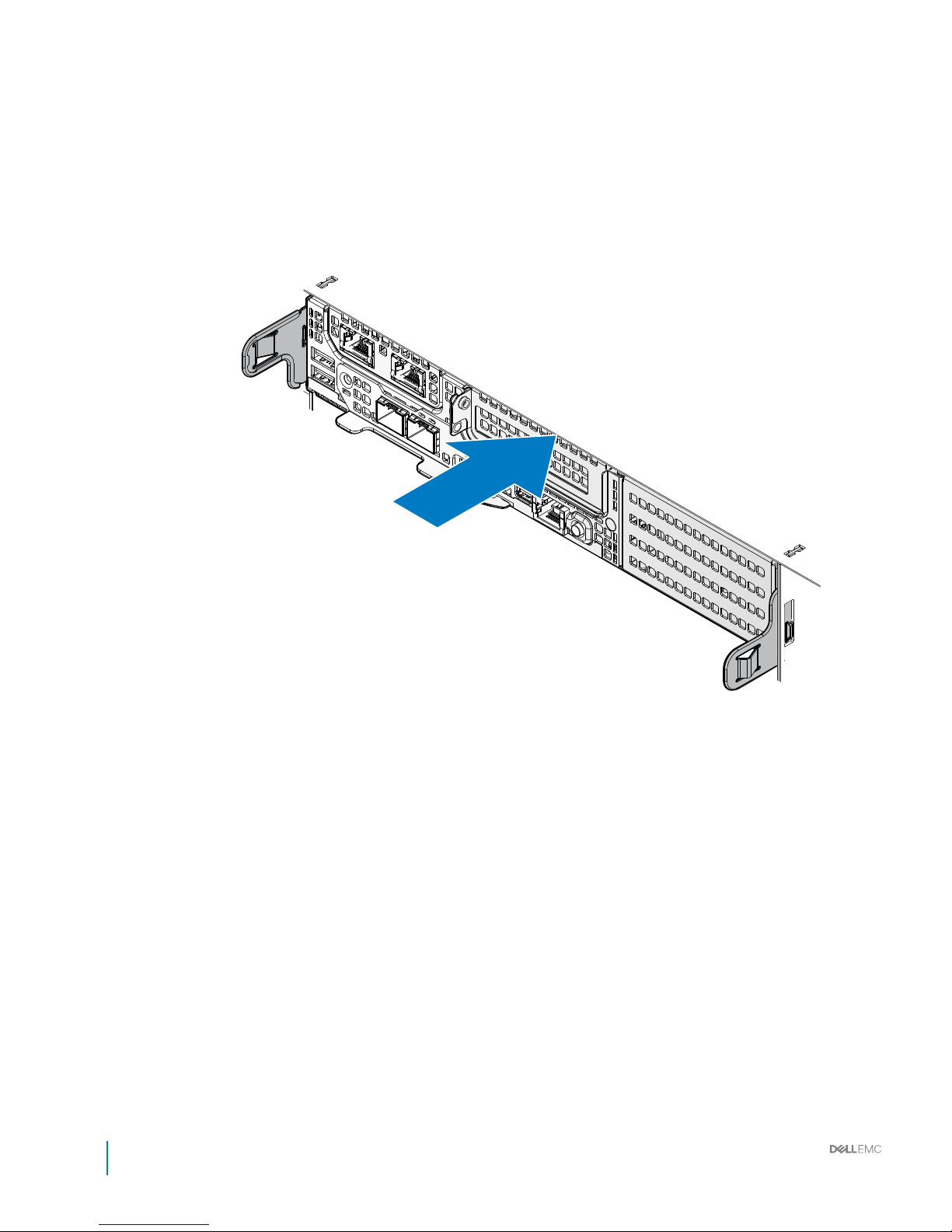
Figure 51. Installing the half-width server
78
Installation and Service Manual
Installing and removing system components
Page 79
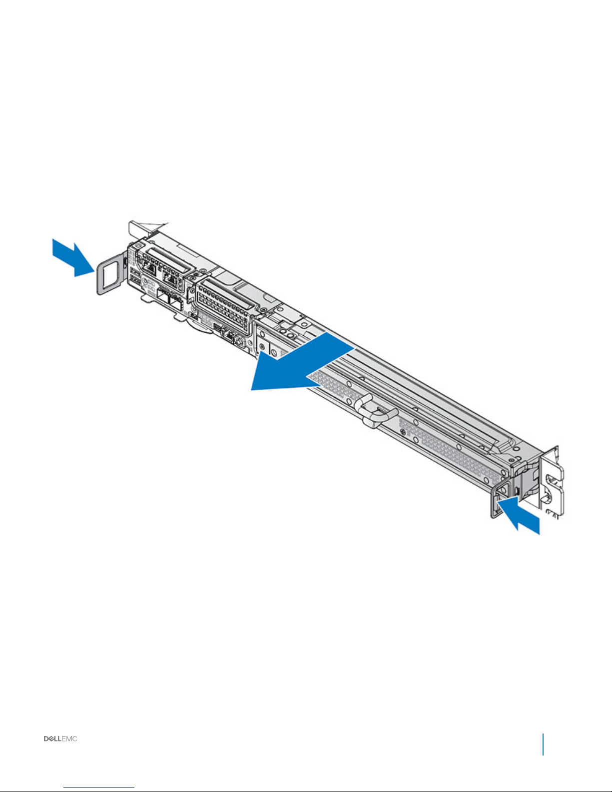
Removing full-width server
Prerequisite
Ensure that you read the Safety instructions.
About this task
Enter the context of your task here (optional). This is where introductory content goes.
Steps
1 Press the release latches on the side of the server.
2 Slide the server out of the block.
Figure 52. Removing full-width server
Installing full-width server
1 Align the server with the bay, and insert the server into the block.
2 Slide the server in until it is fully seated in the block.
The server locks in place after it is properly seated.
Installation and Service Manual
Installing and removing system components
79
Page 80
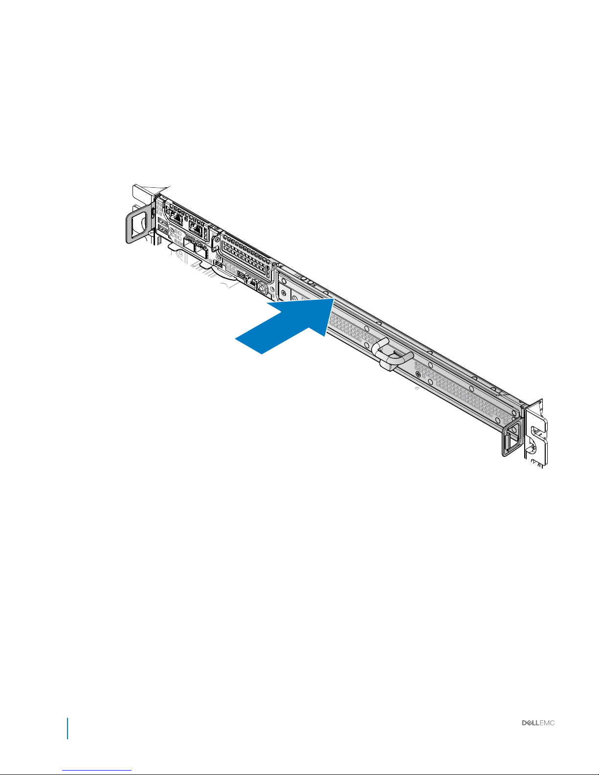
Figure 53. Installing the full-width server
80
Installation and Service Manual
Installing and removing system components
Page 81

Hard disk drive (HDD) trays
The HDD tray is only available for full width and JBOD servers.
Removing HDD tray
Prerequisite
1 Ensure that you read the Safety instructions.
Steps
1 Grasp the tray handle with one hand, and use your thumb to push the plunger up to release the HDD tray.
2 Continue to hold the plunger and use the tray handle to pull the tray out from the chassis.
Installation and Service Manual
Installing and removing system components
81
Page 82
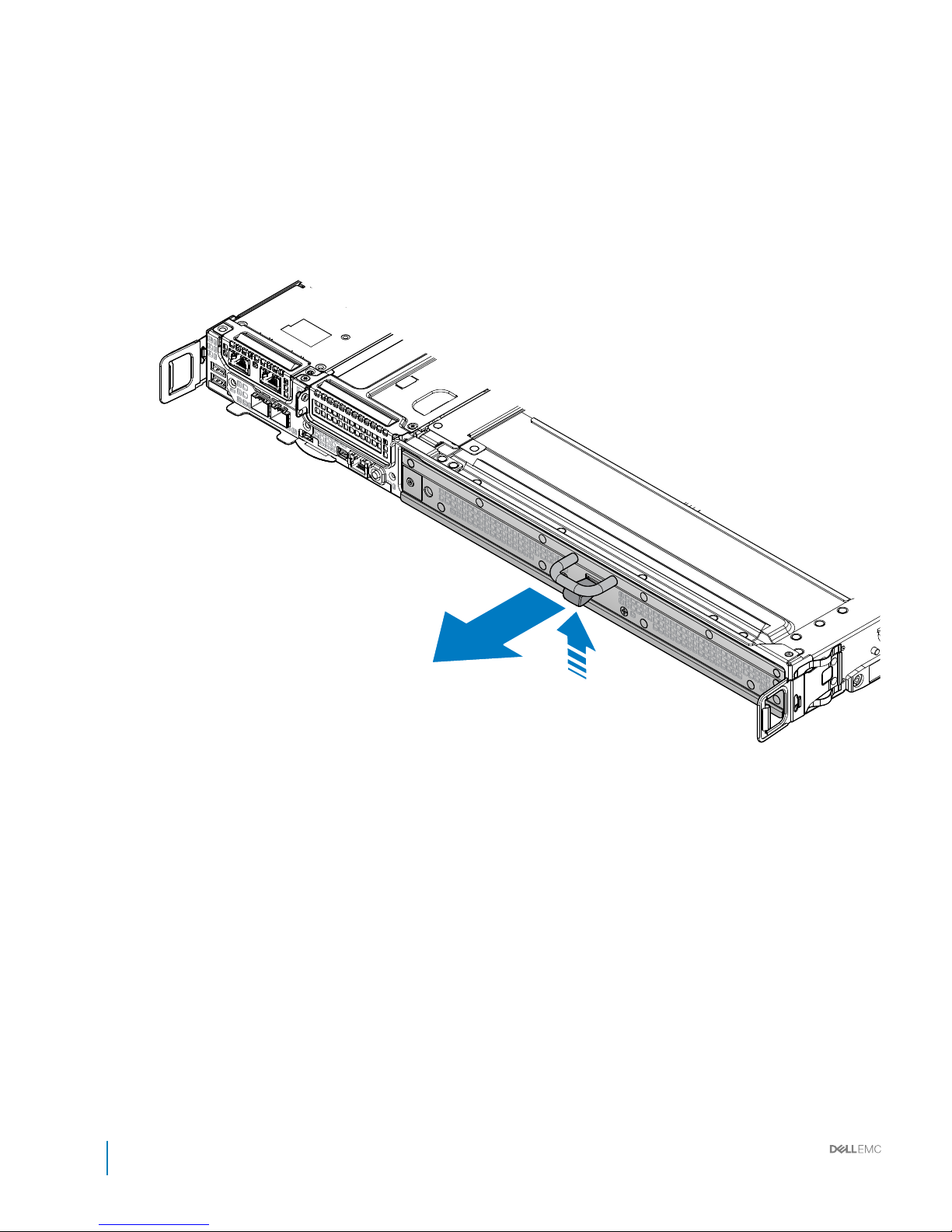
Figure 54. Releasing the HDD tray
82
Installation and Service Manual
Installing and removing system components
Page 83
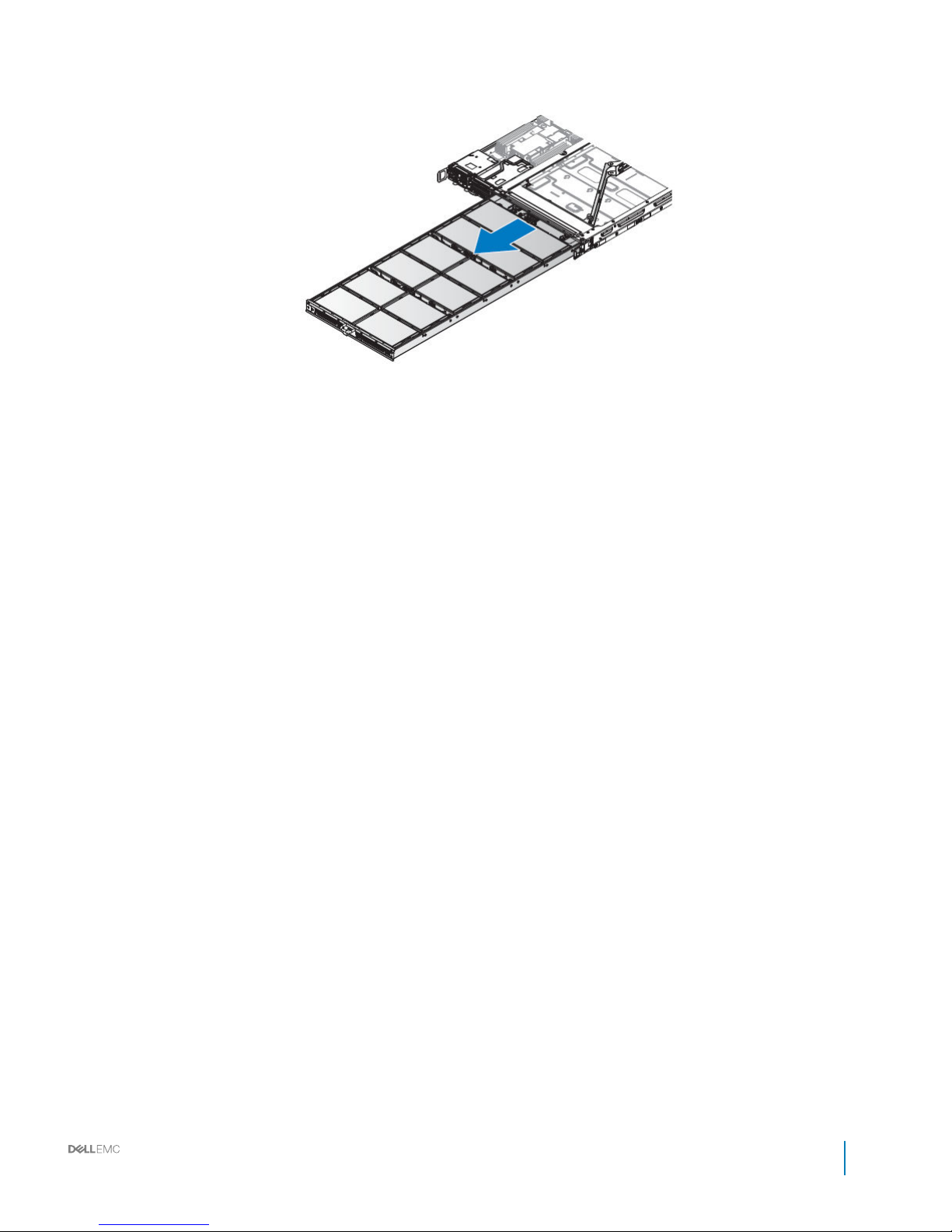
3 Remove the HDD tray from the server.
Figure 55. Removing the HDD tray
4 Remove all HDDs in the HDD tray.
5 Remove the screw and loosen the captive screw on the CMA.
Installation and Service Manual
Installing and removing system components
83
Page 84
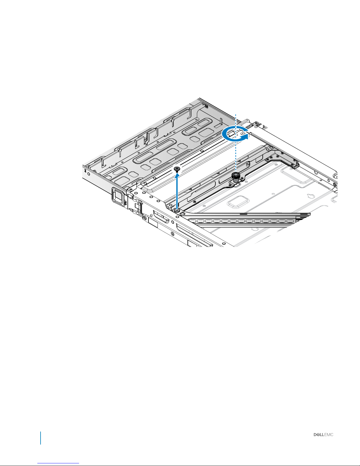
Figure 56. Unfastening the CMA
84
Installation and Service Manual
Installing and removing system components
Page 85
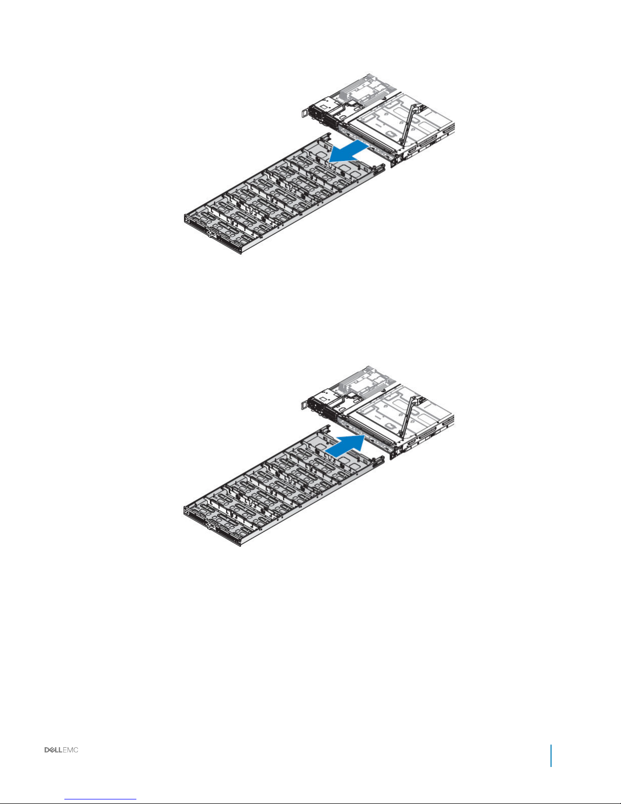
6 Continue to pull out the HDD tray and remove it completely from the chassis.
Figure 57. Removing the HDD tray from the server
Installing HDD tray
1 Insert the HDD tray into the server bay until the HDD tray clears the plunger.
Figure 58. Installing the HDD tray
2 Align the CMA in the server making sure the screw wells on the CMA and server are aligned.
3 Insert a screw in the CMA and tighten it to secure it to the server.
4 Tighten the captive screw on the CMA.
Installation and Service Manual
Installing and removing system components
85
Page 86
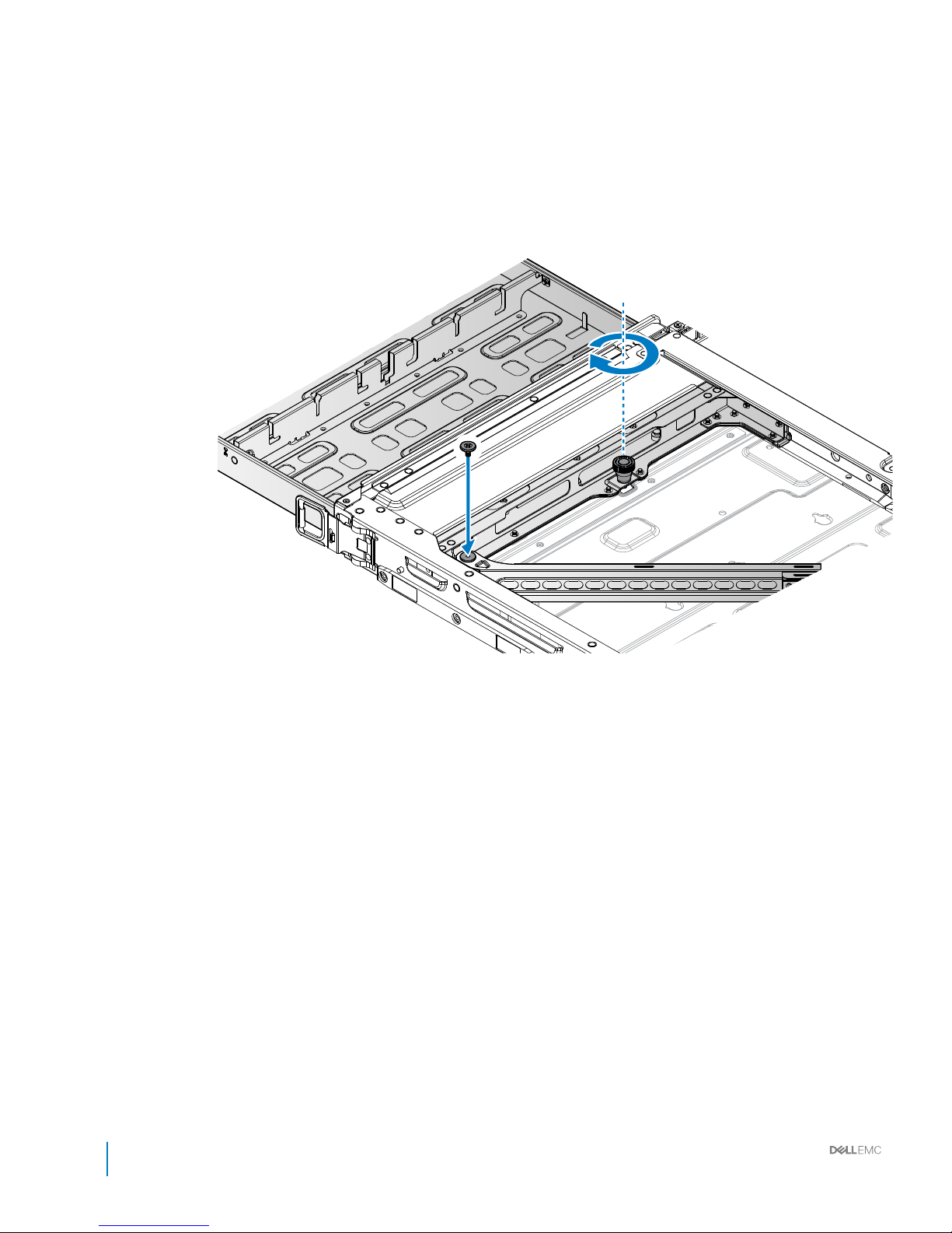
Figure 59. Securing the HDD tray and CMA
86
Installation and Service Manual
Installing and removing system components
Page 87
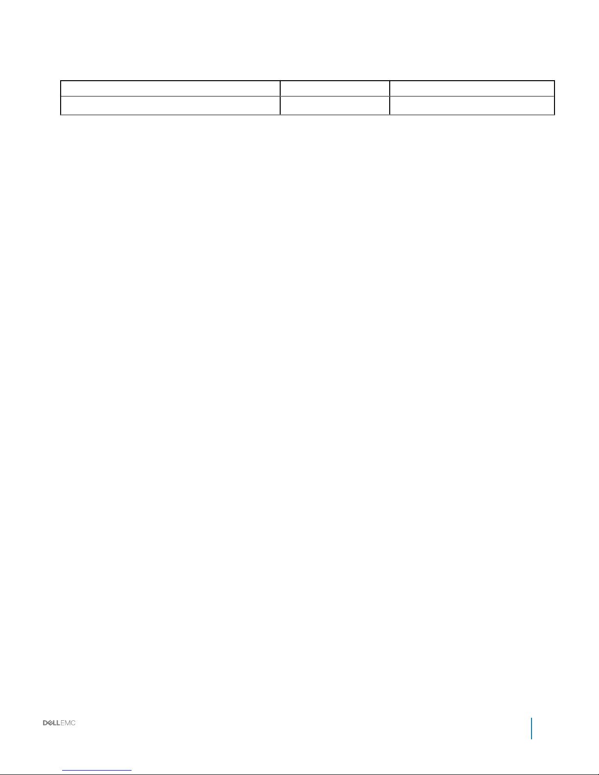
Table 33. Assembly material
Description Quantity Torque (lbs/inch)
#6-32 screw 1 8 ± 0.5
5 Install the HDDs on the HDD tray.
6 Push the HDD tray in until it is fully seated in the chassis.
The HDD tray locks in place after it is properly seated.
Installation and Service Manual
Installing and removing system components
87
Page 88
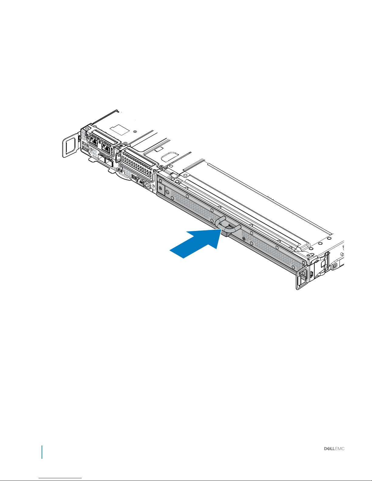
Figure 60. Installing the HDD tray
88
Installation and Service Manual
Installing and removing system components
Page 89

7 Install the full width server. For more details, see Installing full-width server.
Installation and Service Manual
Installing and removing system components
89
Page 90
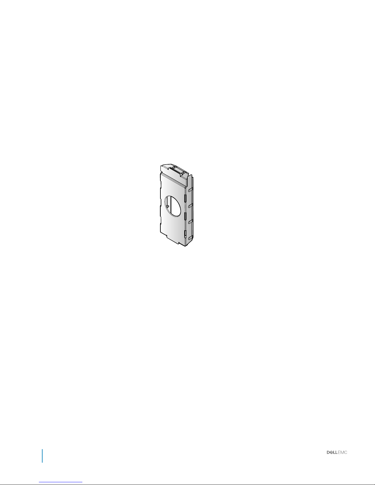
Power supply units (PSU)
90 Installation and Service Manual
Installing and removing system components
Page 91

Removing PSU
Prerequisite
1 Ensure that you read the Safety instructions.
Steps
1 Press down the PSU release latch.
2 Remove the PSU from the power bay.
Installation and Service Manual
Installing and removing system components
91
Page 92
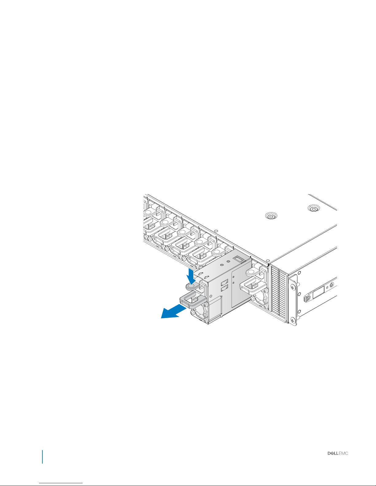
Figure 61. Removing the PSU
92
Installation and Service Manual
Installing and removing system components
Page 93

Installing PSU
1 Align the PSU with the bay. Make sure the connectors are positioned correctly before sliding the PSU into the bay.
2 Insert the PSU in the power bay and push it in until it is properly seated.
The PSU is secured when the release latch locks in place.
Installation and Service Manual
Installing and removing system components
93
Page 94
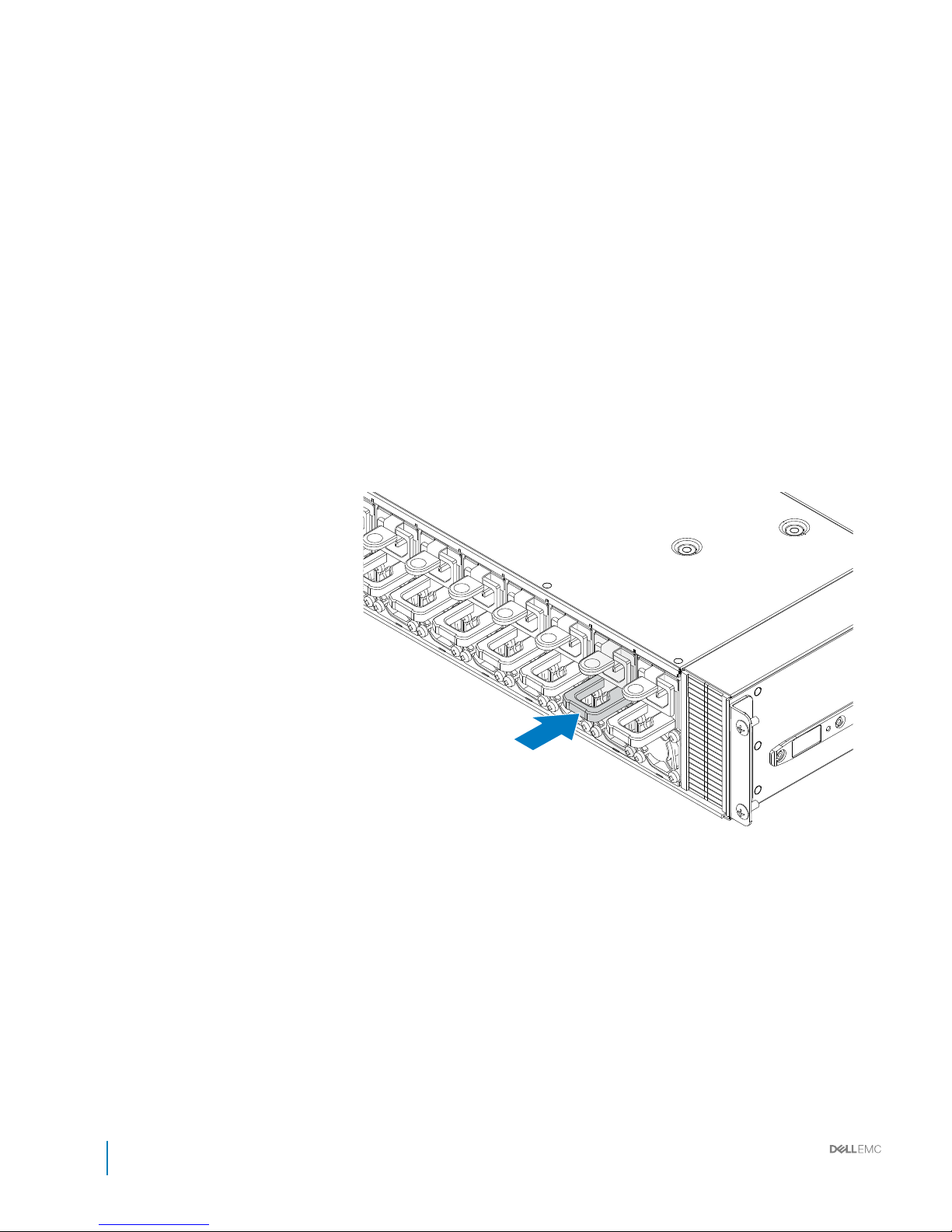
Figure 62. Installing the PSU
94
Installation and Service Manual
Installing and removing system components
Page 95
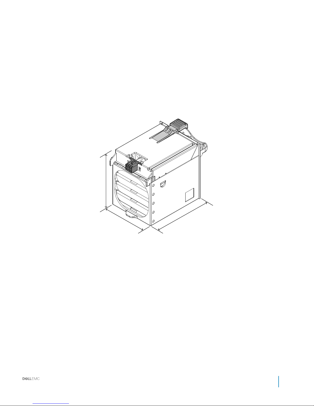
Fan modules
Installation and Service Manual
Installing and removing system components
95
Page 96

Removing fan module
Prerequisite
CAUTION: To prevent damage to the system, remove only a single fan module at a time.
1 Ensure that you read the Safety instructions.
Steps
1 Press up and hold the fan module release latch.
2 Pull the fan module out.
3 Remove the fan module from the fan cage.
96 Installation and Service Manual
Installing and removing system components
Page 97
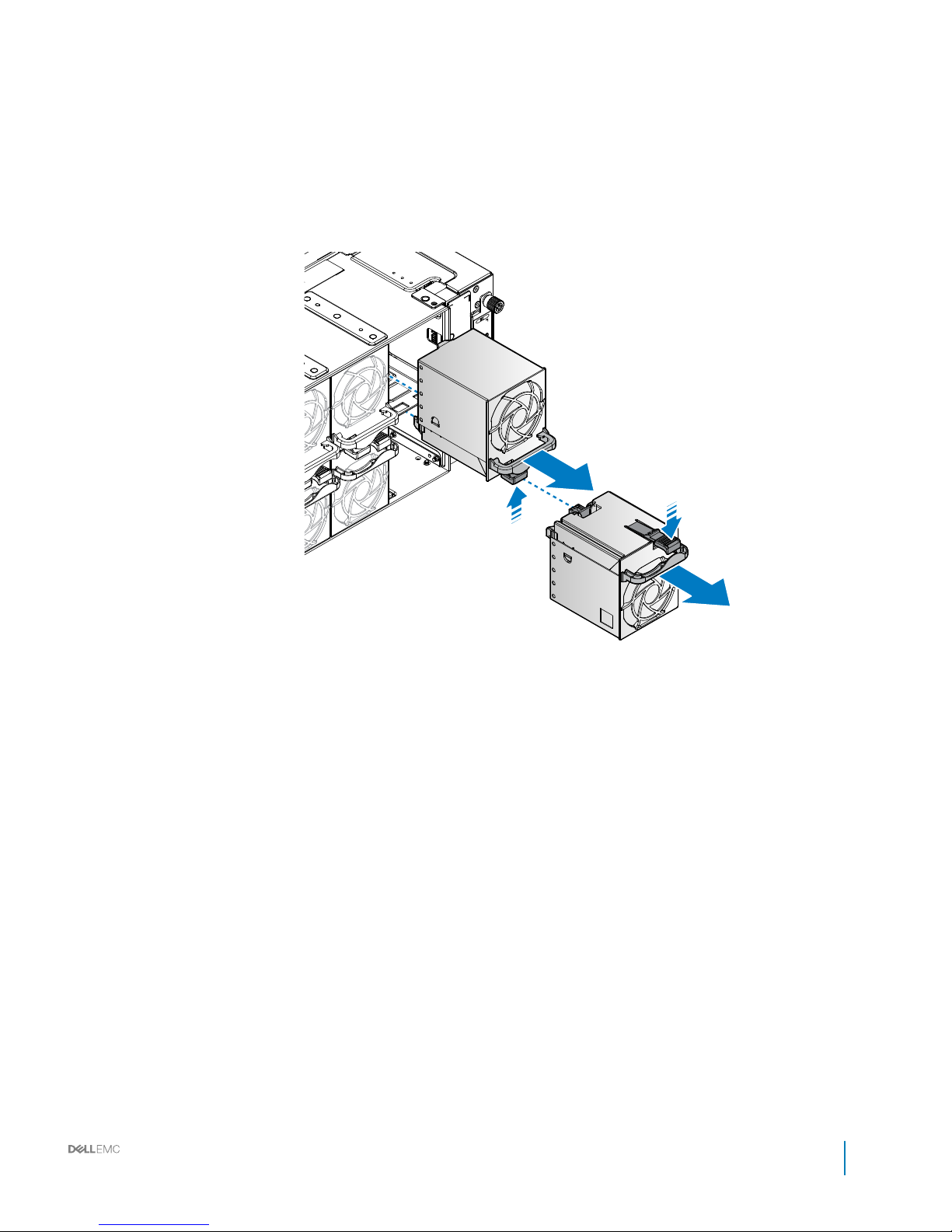
Figure 63. Removing the fan module
Installation and Service Manual
Installing and removing system components
97
Page 98

Installing fan module
1 Align the fan module with the fan cage, making sure the connectors are aligned.
2 Insert the fan module in the fan cage.
The fan module locks in the fan cage.
98 Installation and Service Manual
Installing and removing system components
Page 99
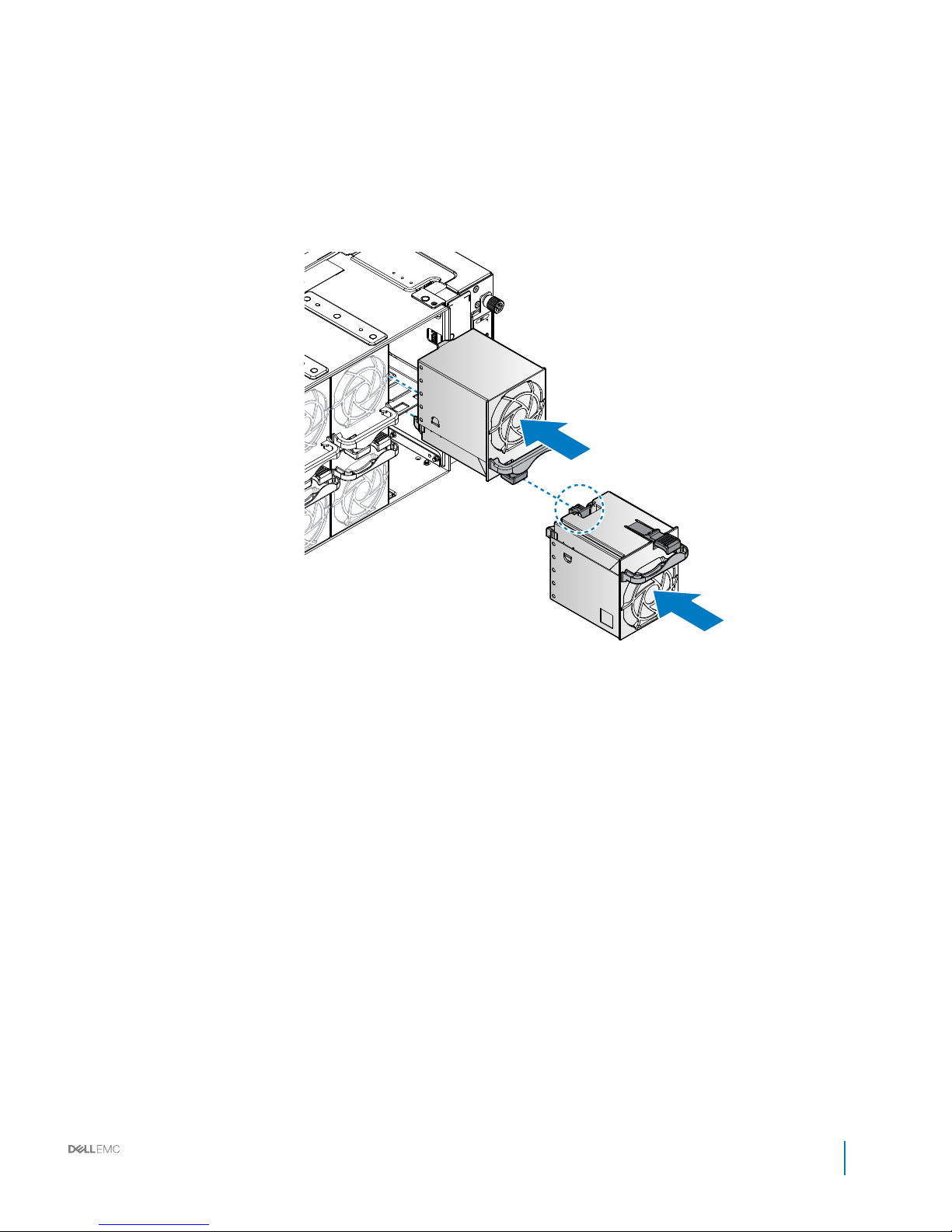
Figure 64. Installing the fan module
Installation and Service Manual
Installing and removing system components
99
Page 100

Fan blocks
Removing fan block
Prerequisite
1 Ensure that you read the Safety instructions.
Steps
1 Loosen the thumb screws.
2 Remove the fan block.
100 Installation and Service Manual
Installing and removing system components
 Loading...