

Page 1

Dell EMC PowerEdge T40
Installation and Service Manual
Regulatory Model: D24M Series
Regulatory Type: D24M003
Page 2

Notes, cautions, and warnings
NOTE: A NOTE indicates important information that helps you make better use of your product.
CAUTION: A CAUTION indicates either potential damage to hardware or loss of data and tells you how to avoid the
problem.
WARNING: A WARNING indicates a potential for property damage, personal injury, or death.
© 2019 Dell Inc. or its subsidiaries. All rights reserved. Dell, EMC, and other trademarks are trademarks of Dell Inc. or its subsidiaries.
Other trademarks may be trademarks of their respective owners.
2019 - 10
Rev. A00
Page 3

Contents
1 About this document.....................................................................................................................6
2 PowerEdge T40 system overview...................................................................................................7
Front view of the system......................................................................................................................................................8
Rear view of the system.......................................................................................................................................................9
Inside view of the system....................................................................................................................................................10
Locating the information tag of your system................................................................................................................... 10
System Information Label.................................................................................................................................................... 11
3 Initial system setup and configuration.......................................................................................... 15
Setting up your system....................................................................................................................................................... 15
Options to install the operating system.............................................................................................................................15
Methods to download firmware and drivers...............................................................................................................15
4 Pre-operating system management applications............................................................................16
Options to manage the pre-operating system applications............................................................................................16
System Setup....................................................................................................................................................................... 16
Viewing System Setup...................................................................................................................................................16
Boot menu.......................................................................................................................................................................16
Navigation keys...............................................................................................................................................................17
System Setup options....................................................................................................................................................17
Updating the BIOS.........................................................................................................................................................23
System and setup password........................................................................................................................................30
PXE boot............................................................................................................................................................................... 31
5 Installing and removing system components.................................................................................32
Safety instructions.............................................................................................................................................................. 32
Before working inside your system................................................................................................................................... 32
After working inside your system...................................................................................................................................... 32
Recommended tools........................................................................................................................................................... 33
System cover....................................................................................................................................................................... 33
Removing the system cover.........................................................................................................................................33
Installing the system cover...........................................................................................................................................34
Front bezel........................................................................................................................................................................... 35
Removing the front bezel.............................................................................................................................................35
Installing the front bezel............................................................................................................................................... 36
Hard drives........................................................................................................................................................................... 37
Removing a drive carrier from the drive bay .............................................................................................................37
Installing a drive carrier into the drive bay..................................................................................................................38
Removing a drive from the drive carrier.....................................................................................................................39
Installing a drive into the drive carrier.........................................................................................................................40
PSU assembly.......................................................................................................................................................................41
Opening the PSU assembly...........................................................................................................................................41
Closing the PSU assembly............................................................................................................................................42
Contents 3
Page 4

Power supply unit................................................................................................................................................................43
Removing the power supply unit................................................................................................................................. 43
Installing the power supply unit ...................................................................................................................................44
Expansion cards...................................................................................................................................................................45
Removing the Expansion card..................................................................................................................................... 45
Installing the expansion card........................................................................................................................................ 47
Memory module...................................................................................................................................................................48
System memory guidelines...........................................................................................................................................48
General memory module installation guidelines......................................................................................................... 49
Removing a memory module........................................................................................................................................50
Installing a memory module...........................................................................................................................................51
System battery.................................................................................................................................................................... 52
Replacing the system battery...................................................................................................................................... 52
Optical drive......................................................................................................................................................................... 53
Removing the optical drive...........................................................................................................................................53
Installing the optical drive............................................................................................................................................. 54
Speaker.................................................................................................................................................................................55
Removing speaker.........................................................................................................................................................55
Installing the speaker.....................................................................................................................................................57
System fan........................................................................................................................................................................... 59
Removing system fan................................................................................................................................................... 59
Installing system fan.......................................................................................................................................................61
Intrusion switch....................................................................................................................................................................62
Removing intrusion switch........................................................................................................................................... 62
Installing intrusion switch..............................................................................................................................................63
Processor and heatsink.......................................................................................................................................................64
Removing heat sink module......................................................................................................................................... 64
Removing the processor...............................................................................................................................................65
Installing the processor.................................................................................................................................................65
Installing heat sink module............................................................................................................................................66
System board.......................................................................................................................................................................68
Removing the system board........................................................................................................................................ 68
Installing the system board...........................................................................................................................................70
Entering the System Service Tag by using the Service Menu................................................................................. 71
Entering the system Service Tag by using System Setup........................................................................................72
Control panel........................................................................................................................................................................ 72
Removing the control panel..........................................................................................................................................72
Installing the control panel............................................................................................................................................73
Power button module..........................................................................................................................................................74
Removing power button module..................................................................................................................................74
Installing power button module....................................................................................................................................75
6 Jumpers and connectors ............................................................................................................ 77
System board jumpers and connectors............................................................................................................................ 77
System board jumper settings........................................................................................................................................... 78
Disabling forgotten password............................................................................................................................................ 79
7 Technical specifications..............................................................................................................80
Chassis dimensions.............................................................................................................................................................. 81
4
Contents
Page 5

System weight......................................................................................................................................................................81
Processor specifications......................................................................................................................................................81
Supported operating systems............................................................................................................................................82
PSU specifications...............................................................................................................................................................82
System fan specifications...................................................................................................................................................82
System battery specifications............................................................................................................................................82
Expansion card specifications............................................................................................................................................82
Memory specifications........................................................................................................................................................83
Storage controller specifications.......................................................................................................................................83
Drive specifications............................................................................................................................................................. 83
Drives.............................................................................................................................................................................. 83
Optical drives..................................................................................................................................................................84
Ports and connectors specifications.................................................................................................................................84
USB ports specifications...............................................................................................................................................84
NIC port specifications..................................................................................................................................................84
Serial connector specifications.................................................................................................................................... 84
DisplayPort specifications.............................................................................................................................................84
Video specifications.............................................................................................................................................................84
Environmental specifications............................................................................................................................................. 84
Thermal restriction matrix............................................................................................................................................ 85
Particulate and gaseous contamination specifications............................................................................................. 86
8 System diagnostics and indicator codes ...................................................................................... 87
Front panel indicator codes................................................................................................................................................87
NIC indicator codes.............................................................................................................................................................88
Power supply unit Built-in Self Test .................................................................................................................................88
Steps to confirm that power supply unit is defective...............................................................................................88
Enhanced Pre-Boot System Assessment — ePSA diagnostics................................................................................... 89
Running the ePSA Diagnostics.................................................................................................................................... 89
Diagnostics........................................................................................................................................................................... 89
Diagnostic error messages.................................................................................................................................................90
System error messages...................................................................................................................................................... 93
9 Getting help...............................................................................................................................94
Recycling or End-of-Life service information.................................................................................................................. 94
Uploading files to Dell Technical Support.........................................................................................................................94
Contacting Dell.................................................................................................................................................................... 94
Accessing system information by using QRL...................................................................................................................95
Quick Resource Locator for PowerEdge T40 system..............................................................................................95
10 Documentation resources.......................................................................................................... 96
Contents
5
Page 6

About this document
This document provides an overview about the system, information about installing and replacing components, technical specifications,
diagnostic tools, and guidelines to be followed while installing certain components.
1
6 About this document
Page 7

PowerEdge T40 system overview
The PowerEdge T40 system is a tower server that supports:
• One Intel Xeon E-series processor or Intel Core i3 processor or Intel Pentium Gold processor
• Up to three 3.5-inch cabled SATA drives
• Up to four UDIMM slots
• One cabled AC power supply unit (PSU)
For more information about supported drives, see the Drive specifications section.
Topics:
• Front view of the system
• Rear view of the system
• Inside view of the system
• Locating the information tag of your system
• System Information Label
2
PowerEdge T40 system overview 7
Page 8
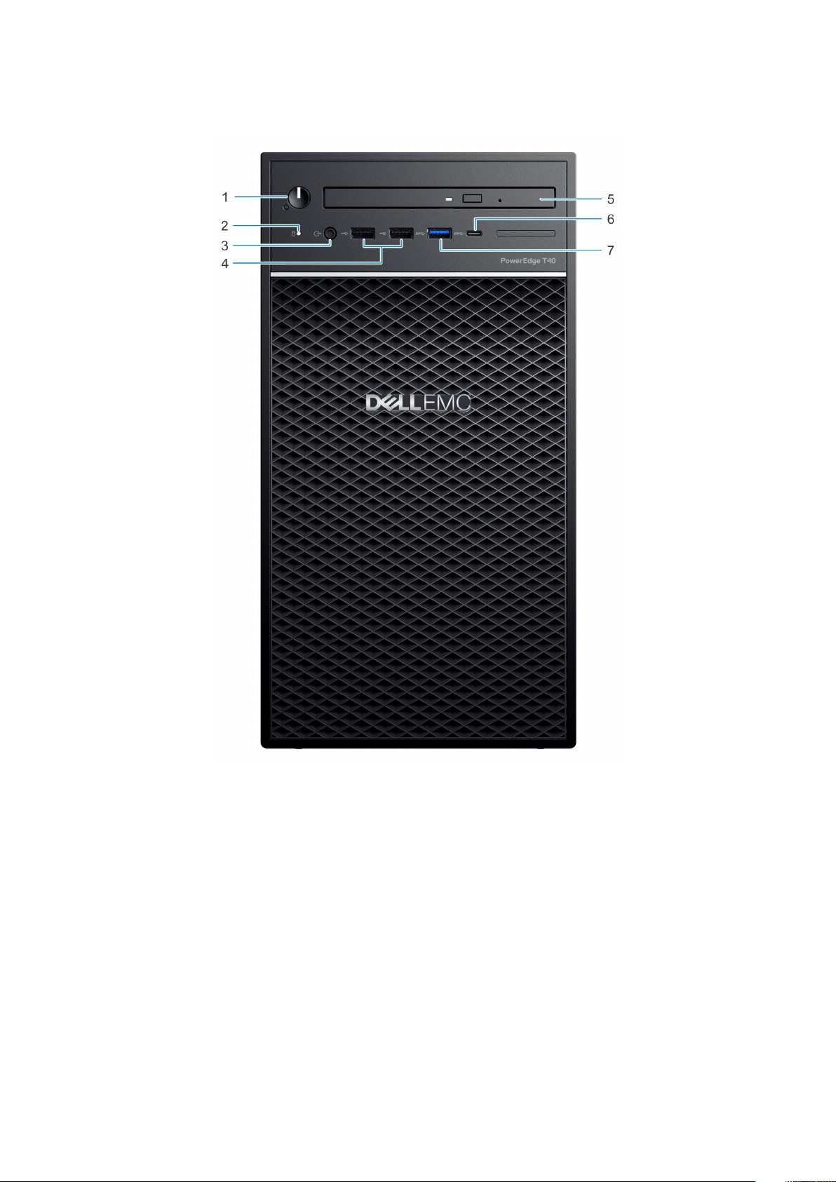
Front view of the system
Figure 1. Front view of the system
Power button/Diagnostics indicator 2. Drive activity LED indicator
1.
3. 3.5 mm Headphone port 4. USB 2.0 Type-A port (2)
5. Optical drive 6. USB 3.1 Type-C port
7. USB 3.0 Type-A port
For more information about the ports, see the Ports and connectors specifications section.
8
PowerEdge T40 system overview
Page 9
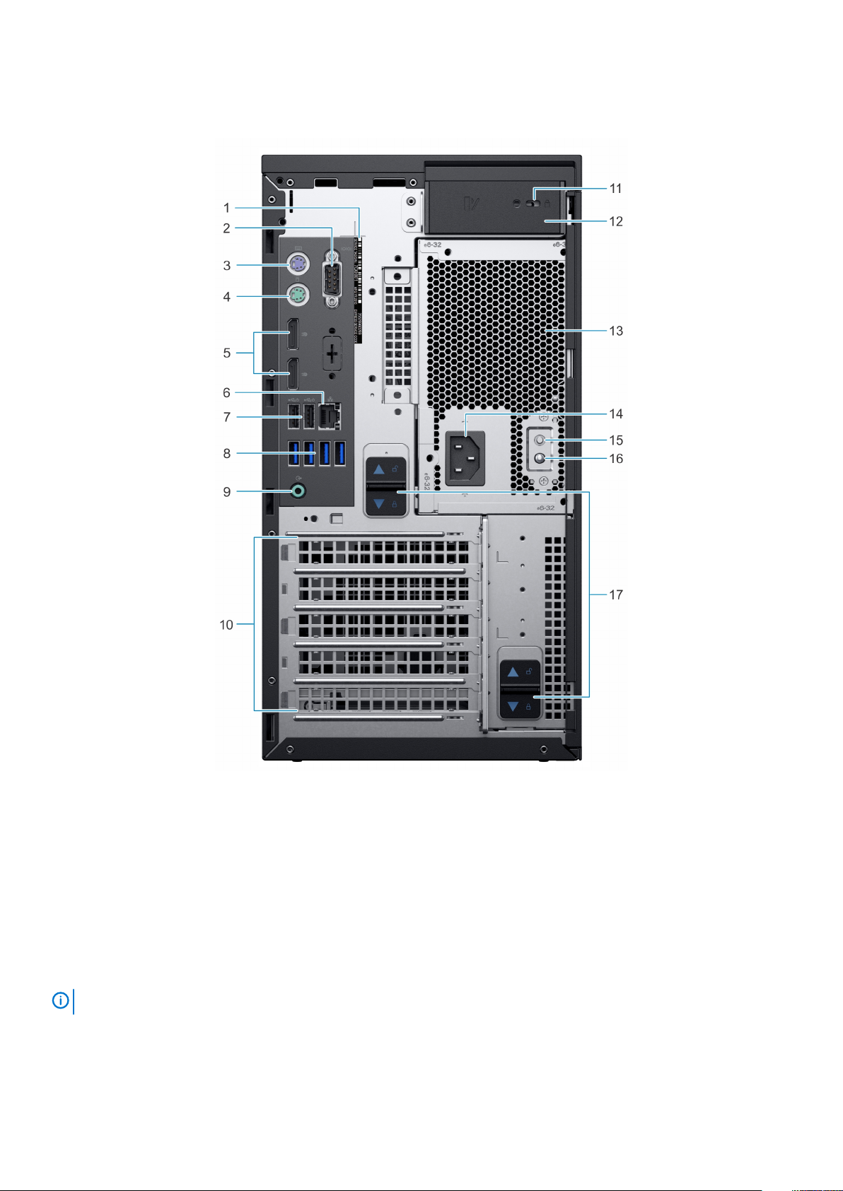
Rear view of the system
Figure 2. Rear view of the system
Service tag 2. Serial port
1.
3. PS2 port (Keyboard) 4. PS2 port (Mouse)
5. Display Port (2) 6. NIC port
7. USB 2.0 Type-A with SmartPower (2) 8. USB 3.0 Type-A ports (4)
9. Audio line-out port 10. Expansion card slots (4)
11. Kensington/padlock slot 12. System cover release latch
13. Power Supply Unit (PSU) 14. Power connector port
15. Power Supply Unit (PSU) Built-in Self Test (BIST) button 16. Power Supply Unit (PSU) Built-in Self Test (BIST) LED
17. PSU assembly release latch
NOTE: For more information about the ports and connectors, see the Ports and connectors specifications section.
PowerEdge T40 system overview 9
Page 10
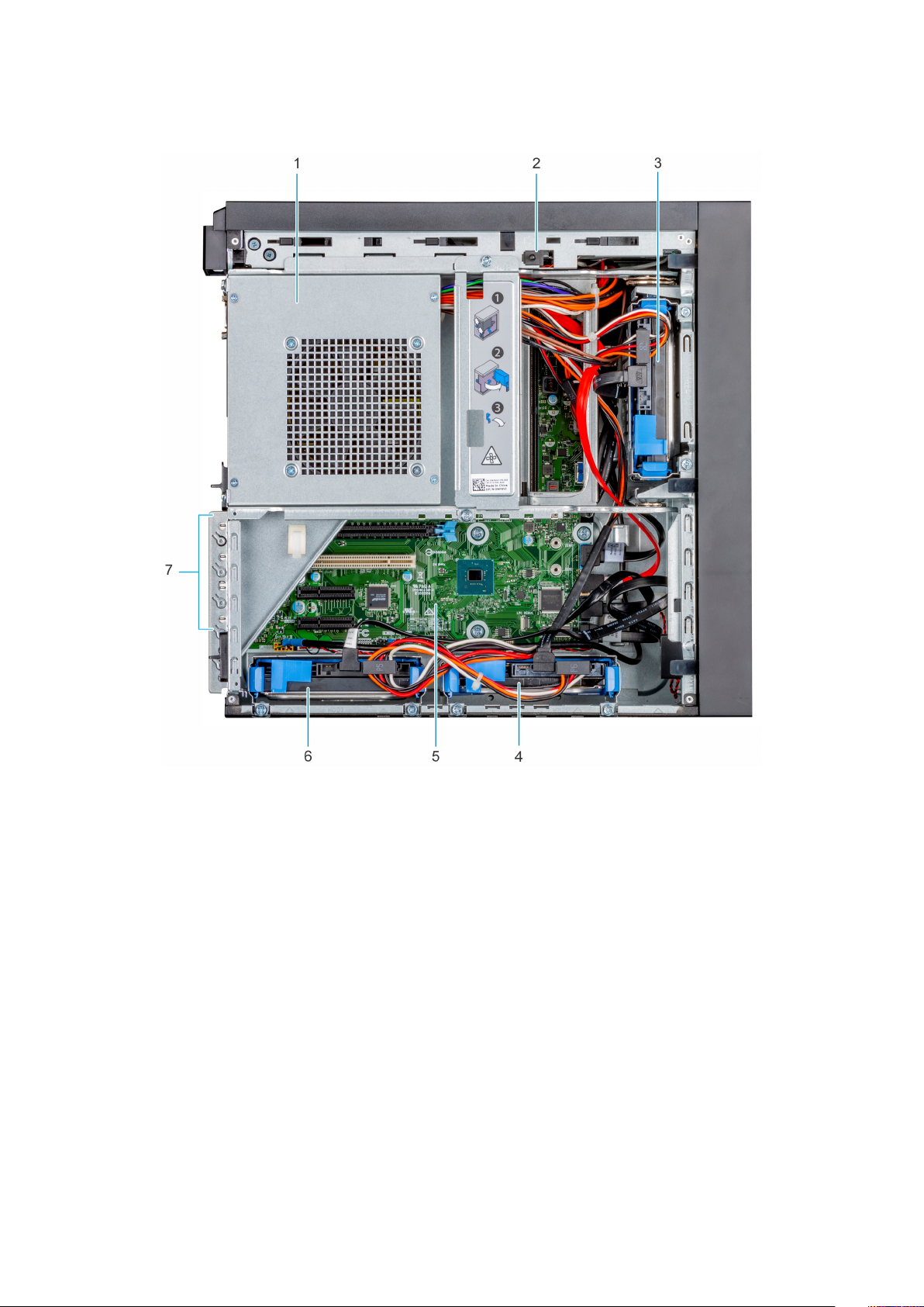
Inside view of the system
Figure 3. Inside view of the system
Power Supply Unit (PSU) 2. Intrusion switch
1.
3. Drive 01 4. Drive 02
5. System board 6. Drive 03
7. Expansion card slots (4)
Locating the information tag of your system
Your system is identified by a unique Express Service Code and Service Tag number. The Express Service Code is found on a sticker on
the top surface of the system and Service Tag is found on a sticker on the rear of the system. This information is used by Dell to route
support calls to the appropriate personnel.
10
PowerEdge T40 system overview
Page 11
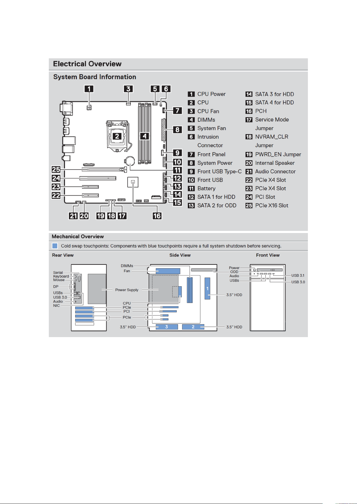
System Information Label
Figure 4. Service Information
PowerEdge T40 system overview
11
Page 12
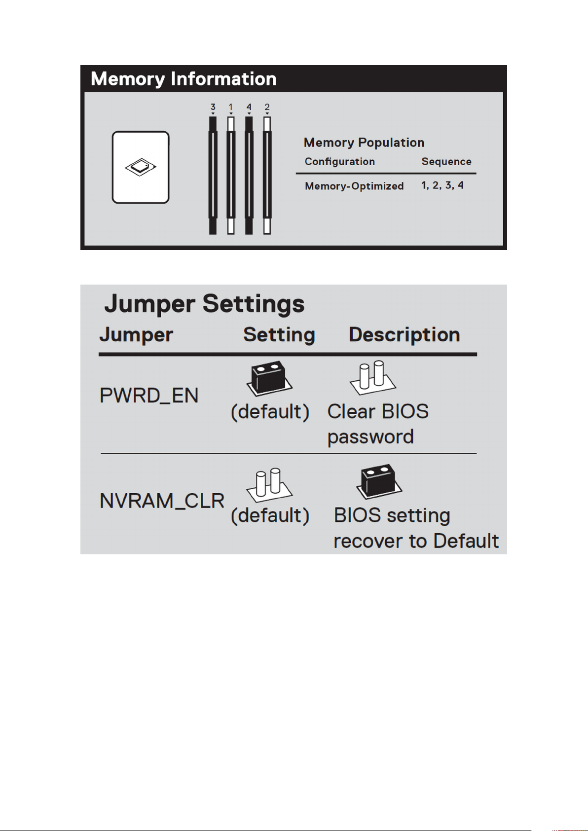
Figure 5. Memory information
Figure 6. Jumper Settings
12
PowerEdge T40 system overview
Page 13
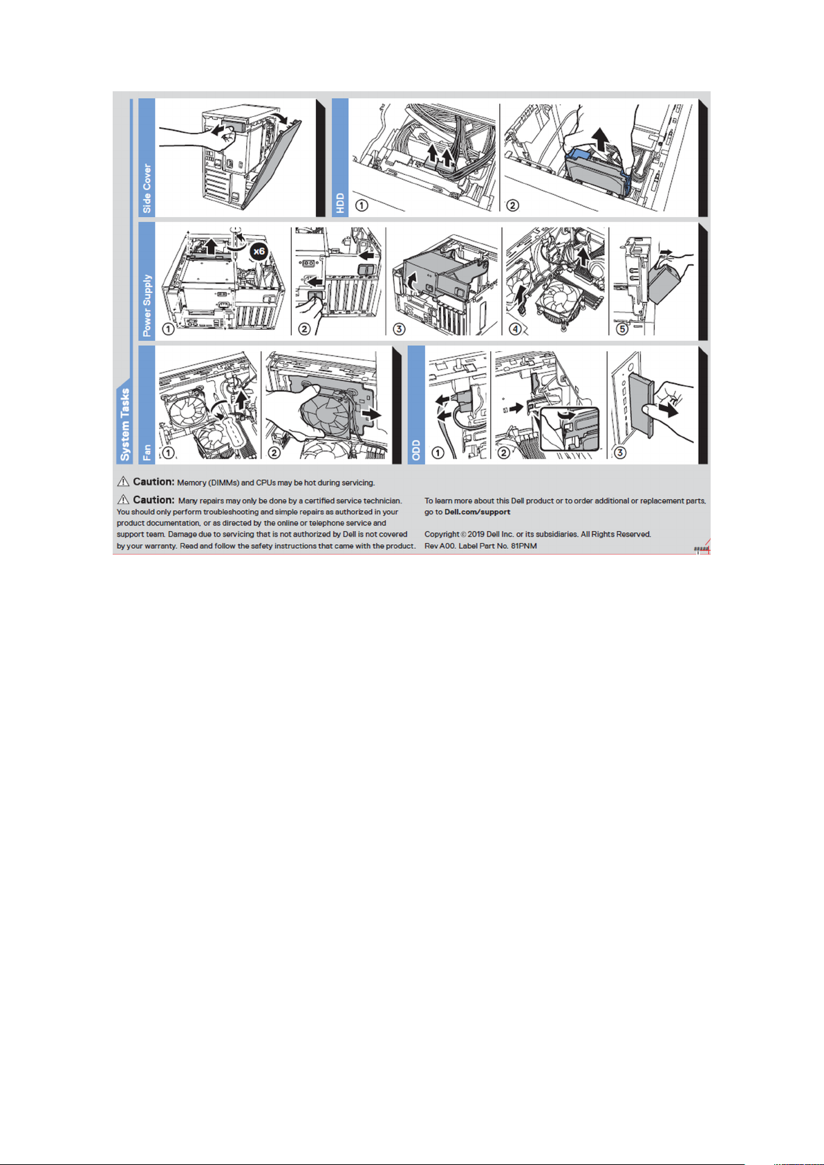
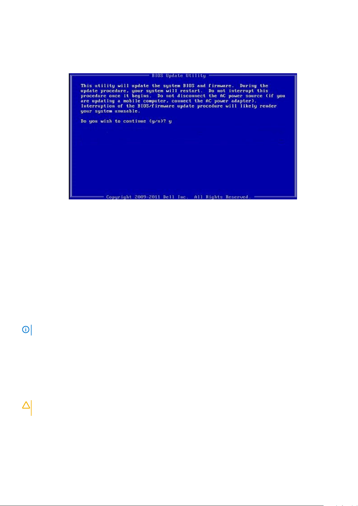
Figure 7. System task
PowerEdge T40 system overview
13
Page 14

Figure 8. Quick resource locator
14
PowerEdge T40 system overview
Page 15

Initial system setup and configuration
Setting up your system
Perform the following steps to set up your system:
Steps
1. Unpack the system.
2. Connect the peripherals to the system.
3. Connect the system to its electrical outlet.
4. Power on the system by pressing the power button.
5. Power on the attached peripherals.
For more information about setting up your system, see the Getting Started Guide that shipped with your system.
Options to install the operating system
If the system is shipped without an operating system, install the supported operating system by using one of the following resources:
3
Table 1. Resources to install the operating system
Resources Location
Dell Systems Management Tools and Documentation media Dell.com/operatingsystemmanuals
Supported operating systems on Dell PowerEdge systems Dell.com/ossupport
Installation and How-to videos for supported operating systems on
Dell PowerEdge systems
Supported Operating Systems for Dell PowerEdge Systems
Methods to download firmware and drivers
You can download the firmware and drivers from the Dell support site at Dell.com/support/drivers.
Downloading the drivers and firmware
Dell EMC recommends that you download and install the latest BIOS, drivers, and systems management firmware on your system.
Prerequisites
Ensure that you clear the web browser cache before downloading the drivers and firmware.
Steps
1. Go to Dell.com/support/drivers.
2. In the Drivers & Downloads section, type the Service Tag of your system in the Service Tag or Express Service Code box, and
then click
3. Click Drivers & Downloads.
The drivers that are applicable to your selection are displayed.
4. Download the drivers to a USB drive, CD, or DVD.
Submit.
NOTE:
Service Tag, or in General support, navigate to your product.
If you do not have the Service Tag, select Detect My Product to allow the system to automatically detect your
Initial system setup and configuration 15
Page 16

Pre-operating system management
applications
You can manage basic settings and features of a system without booting to the operating system by using the system firmware.
Topics:
• Options to manage the pre-operating system applications
• System Setup
• PXE boot
Options to manage the pre-operating system applications
Your system has the following options to manage the pre-operating system applications:
• System Setup
• Preboot Execution Environment (PXE)
4
System Setup
By using the System Setup screen, you can configure the BIOS settings and device settings of your system.
System Setup enables you to manage your system hardware and specify BIOS level options. From the System setup, you can:
• Change the NVRAM settings after you add or remove hardware
• View the system hardware configuration
• Enable or disable integrated devices
• Set performance and power management thresholds
• Manage your system security
Viewing System Setup
To view the System Setup screen,
Steps
Press F2 immediately after a power-on or re-boot.
NOTE:
restart your system and try again.
Boot menu
To enter Boot Manager: Power on, or restart your system. Press F12 when the Dell logo appears to initiate a one-time boot menu with a
list of the valid boot devices for the system. Diagnostics and BIOS Setup options are also included in this menu. The devices listed on the
boot menu depend on the bootable devices in the system. This menu is useful when you are attempting to boot to a particular device or to
bring up the diagnostics for the system. Using the boot menu does not change the boot order stored in the BIOS.
The options are:
• UEFI Boot:
• Windows Boot Manager
If your operating system begins to load before you press F2, wait for the system to finish booting, and then
16 Pre-operating system management applications
Page 17

• Other Options:
• BIOS Setup
• BIOS Flash Update
• Diagnostics
• Change Boot Mode Settings
Navigation keys
NOTE: For most of the System Setup options, changes that you make are recorded but do not take effect until you
restart the system.
Keys Navigation
Up arrow Moves to the previous field.
Down arrow Moves to the next field.
Enter Selects a value in the selected field (if applicable) or follow the link in the field.
Spacebar Expands or collapses a drop-down list, if applicable.
Tab Moves to the next page.
NOTE: For the standard graphics browser only.
Esc Moves to the previous page. Pressing Esc in the main screen displays a message that prompts you to save any
unsaved changes and restarts the system.
System Setup options
NOTE:
Table 2. General
Option Description
System Information Lists the primary hardware features of your system.
Boot Sequence Allows you to change the order in which the system attempts to find an operating system.
Boot List Options Allows you to change the boot list option.
Advanced Boot Options Allows you to enable Legacy Option ROMs
Depending on your system and its installed devices, the items listed in this section may or may not appear.
• System Information
• Memory Configuration
• PCI Information
• Processor Information
• Device Information
• Windows Boot Manager
• Onboard NIC
• Onboard NIC
• Legacy External Devices
• UEFI (Default setting)
• Enable Legacy Option ROMs (Default setting: enabled)
• Enable Attempt Legacy Boot (Default setting: not enabled)
UEFI Boot Path Security Allows you to control whether the system prompts the user to enter the Admin password when
booting to a UEFI boot path.
• Always, Except Internal HDD (Default setting)
• Always, Except Internal HDD & PXE
Pre-operating system management applications 17
Page 18

Option Description
• Always
• Never
Date/Time Allows you to set the date and time.
NOTE: The changes to the system date and time takes effect immediately.
Table 3. System configuration
Option Description
Integrated NIC Allows you to configure the on-board LAN controller.
• Enable UEFI Network Stack
• Disabled
• Enabled
• Enabled w/PXE (Default setting)
Serial Port Identifies and defines the serial port settings. You can set the serial port to:
• Disabled
• COM1 (Default setting)
• COM2
• COM3
• COM4
SATA Operation Allows you to configure the internal SATA hard-drive controller.
• Disabled
• AHCI
• RAID On (Default setting)
Drives Allows you to configure the SATA drives on board.
• SATA-0
• SATA-1
• SATA-2
• SATA-3
Default setting: All drives are enabled.
SMART Reporting This field controls if the hard drive errors for the integrated drives are reported during system
startup. This technology is part of the SMART (Self Monitoring Analysis and Reporting
Technology) specification.
• Enable SMART Reporting (Default setting: not enabled)
USB Configuration Allows you to enable or disable the USB configuration.
• Enable USB Boot Support (Default setting)
• Enable Front USB Ports (Default setting)
• Enable rear USB Ports (Default setting)
Front USB Configuration Allows you to enable or disable the front USB configuration.
• Front Port 1 (Left)
• Front Port 2 (Center)
• Front Port 3 (Right)*
• Front Port 4 (Type C)*
*Denotes a USB 3.0–capable port
Rear USB Configuration Allows you to enable or disable the rear USB configuration.
• Rear Port 1 (Upper Left)
• Rear Port 2 (Upper Right)
• Rear Port 3 (Left)*
18 Pre-operating system management applications
Page 19

Option Description
• Rear Port 4 (Center Left)*
• Rear Port 5 (Center Right)*
• Rear Port 6 (Right)*
*Denotes a USB 3.1 Gen 1–capable port
Memory Map IO above 4 GB Allows you to enable or disable memory mapping IO above 4 GB.
The option is enabled by Default setting.
Audio Allows you enable or disable the audio feature.
• Enable Audio(Default setting)
• Enable Internal Speaker (Default setting)
Miscellaneous devices Allows you to enable or disable various on-board devices.
• Enable PCI Slot (Default setting)
Table 4. Video
Option Description
Multi-Display
NOTE: The processor must
be Intel Graphic Device
(IGD) capable to view this
option.
Allows you to enable or disable multi display feature.
Default setting: not enabled.
NOTE: Ensure to install an
additional GPU to utilize this
option.
Primary Display Allows you to configure primary video controller when there are multiple controllers available.
• Auto (Default setting)
• Intel HD Graphics
Table 5. Security
Option Description
Admin Password This option allows you to enable or disable admin passwords for the system (Default setting: not
enabled).
System Password This option allows you to enable or disable system passwords for the system (Default setting: not
enabled).
Strong Password This option allows you to enable or disable strong passwords for the system (Default setting: not
enabled).
Password Configuration Allows you to control the minimum and maximum number of characters allowed for a administrative
password and the system password. The range of characters is between 4 and 32.
Password Bypass This option lets you bypass the system (Boot) password and the internal HDD password prompts
during a system restart.
• Disabled — Always prompt for the system and internal HDD password when they are set. This
option is enabled by Default setting.
• Reboot Bypass — Bypass the password prompts on Restarts (warm boots).
NOTE: The system will always prompt for the system and internal HDD passwords
when powered on from the off state (a cold boot). Also, the system will always prompt
for passwords on any module bay HDDs that may be present.
Password Change This option allows you to determine whether changes to the System and Hard Disk passwords are
permitted when an administrator password is set.
Pre-operating system management applications 19
Page 20

Option Description
Allow Non-Admin Password Changes - This option is enabled by Default setting.
TPM 2.0 Security
NOTE: TPM function is not
applied to China and
Russia.
Chassis Intrusion This field controls the chassis intrusion feature.
OROM Keyboard Access
Allows you to control whether the Trusted Platform Module (TPM) is visible to the operating
system.
• TPM On (Default setting)
• Clear
• PPI Bypass for Enable Commands (Default setting)
• PPI Bypass for Disable Commands
• PPI Bypass for Clear Commands
• Attestation Enable (Default setting)
• Key Storage Enable (Default setting)
• SHA-256 (Default setting)
Choose any one option:
• Disabled
• Enabled (Default setting)
Choose any one of the option:
• Disabled
• Enabled (Default setting)
• On-Silent
• Disabled
• Enabled (Default setting)
• One Time Enable
Admin Setup Lockout Allows you to prevent users from entering Setup when Admin password is set (Default setting: not
enabled).
Master Password Lockout Allows you to prevent users from entering Setup when Master password is set (Default setting: not
enabled).
SMM Security Mitigation Allows you to enable or disable additional UEFI SMM Security Mitigation protections (Default setting:
not enabled).
Table 6. Secure Boot
Option Description
Secure Boot Enable The option is not enabled by Default setting.
Secure Boot Mode
Expert Key Management Allows you to enable or disable Custom Mode Key Management.
Table 7. Intel Software Guard Extensions
• Deployed Mode (Default setting)
• Audit Mode
• Enable Custom Mode (This option is not enabled by Default setting)
If Enabled,
• PK (Default setting)
• KEK
• db
• dbx
Option Description
Intel SGX Enable Allows you to enable or disable Intel Software Guard Extensions.
• Disabled
20 Pre-operating system management applications
Page 21

Option Description
• Enabled
• Software controlled (Default setting)
Enclave Memory Size Allows you to change the Intel Software Guard Extensions Enclave Reserve Memory size.
• 32 MB
• 64 MB
• 128 MB
Table 8. Performance
Option Description
Multi Core Support This field specifies whether the processor will have one or all cores enabled. The performance of
some applications will improve with the additional cores. This option is enabled by Default setting.
Allows you to enable or disable multi-core support for the processor.
• All (Default setting)
• 1
• 2
• 3
NOTE:
• The options displayed could be different depending on the installed processor.
• The options depend on the number of cores supported by the installed processor
(All, 1, 2, N-1 for N-Core Processors)
Intel SpeedStep Allows you to enable or disable the Intel SpeedStep feature.
Default setting: Enable Intel SpeedStep
C-States Control Allows you to enable or disable the additional processor sleep states (depends on the processor
installed).
C states (This option is selected by Default setting)
Cache Prefetch
Intel TurboBoost
Hyper-Thread Control
Dell Reliable Memory
Technology (RMT)
• Hardware Prefetcher (Default setting)
• Adjacent Cache Prefetch (Default setting)
When Hardware Prefetcher is enabled, the processor’s hardware prefetcher will automatically
prefetch data and code for the processor
When Adjacent Cache is enabled, the process will retrieve the currently requested cache line, as
well as subsequent cache line.
Allows you to enable or disable the Intel TurboBoost mode of the processor.
The option Intel TurboBoost is set by Default setting.
Allows you to enable or disable the HyperThreading in the processor.
• Disabled
• Enabled—Default setting
Allows you to enable or disable the Dell RMT in the processor.
• Disabled
• Enabled (Default setting)
Table 9. Power management
Option Description
AC Recovery Specifies how the system will respond when AC power is applied after a AC power loss. You can
set the AC Recovery to:
• Power Off
Pre-operating system management applications 21
Page 22

Option Description
• Power On
• Last Power State (Default setting)
Enable Intel Speed Shift
Technology
Auto On Time Allows you to set the time at which the system must turn on automatically.
Fan Control Override Allows you to control the speed of the system fan.
USB Wake Support
Wake on LAN This option allows the system to power up from the off state when triggered by a special LAN
Table 10. POST behavior
Allows you to enable or disable Intel Speed Shift Technology support. The option Enable Intel
Speed Shift Technology is set by Default setting.
• Disabled (Default setting)
• Every Day
• Weekdays
• Select Days
The option Fan Control Override is not enabled by Default setting.
Allows you to enable or disable the USB Wake Support.
• Disabled (Default setting)
• Enabled
signal. Wake-up from the Standby state is unaffected by this setting and must be enabled in the
operating system. This feature only works when the system is connected to AC power supply.
• Disabled (Default setting)
• LAN Only
• LAN with PXE Boot
Option Description
Numlock LED Allows you to specify if the NumLock function is enabled when the system boots. This option is
enabled by Default setting.
Keyboard Errors Specifies whether keyboard related errors are reported when it boots. This option is enabled by
Default setting.
Extend BIOS POST Time This option creates an additional pre-boot delay.
• 0 seconds (Default setting)
• 5 seconds
• 10 seconds
Warnings and Errors This option causes the boot process to only pause when warning or errors are detected. Choose
any one of the option:
• Prompt on Warnings and Errors (Default setting)
• Continue on Warnings
• Continue on Warnings and Errors
Table 11. Manageability
Option Description
Intel AMT Capability This option is selected as Enabled by Default setting.
USB provision This option is not selected by Default setting.
MEBx Hotkey This option is selected by Default setting.
22 Pre-operating system management applications
Page 23

Table 12. Virtualization support
Option Description
Virtualization This option specifies whether a Virtual Machine Monitor (VMM) can utilize the additional hardware
capabilities provided by Intel Virtualization technology.
• Enable Intel Virtualization Technology - This option is enabled by Default setting.
VT for Direct I/O Enables or disables the Virtual Machine Monitor (VMM) from utilizing the additional hardware
capabilities provided by Intel Virtualization technology for direct I/O.
• Enable VT for Direct I/O - This option is enabled by Default setting.
Trusted Execution Allows you to specify whether a Measured Virtual Machine Monitor (MVMM) can utilize the
additional hardware capabilities provided by Intel Trusted Execution Program.
• Trusted Execution - This option is disabled by Default setting.
Table 13. Maintenance
Option Description
Service Tag Displays the service tag of your system.
Asset Tag Allows you to create a system asset tag if an asset tag is not already set. This option is disabled by
Default setting.
SERR Messages Allows you to control the SERR message mechanism. This option is enabled by Default setting.
Some graphics cards require that the SERR message mechanism be disabled.
BIOS Downgrade Allows you to control the flashing of the system firmware to previous revisions. This option is
disabled by Default setting.
Data Wipe Allows you to securely erase data from all internal storage devices. This option is disabled by
Default setting.
BIOS Recovery Allows you to recover from certain corrupted BIOS conditions using a recovery file. This option is
enabled by Default setting.
First Power On Date This option is not set by Default setting.
Table 14. System Logs
Option Description
BIOS events Displays the system event log and allows you to clear the log.
• Clear Log
Table 15. Advanced Configurations
Option Description
ASPM Allows you to set the Active State Power Management level:
• Auto (Default setting)
• Disabled
• L1 Only
PCIe Linkspeed Allows you to select the max PCIe link speed attainable by devices within the system.
• Auto (Default setting)
• Gen1
• Gen2
Updating the BIOS
Prerequisites
It is recommended to update your BIOS (System Setup), when you replace the system board or if an update is available.
Pre-operating system management applications
23
Page 24

About this task
NOTE: If BitLocker is enabled, it must be suspended prior to updating the system BIOS, and then re-enabled after the
BIOS update is completed.
Steps
1. Restart the system.
2. Go to Dell.com/support.
3. Enter the Service Tag or Express Service Code and click Submit.
NOTE: To locate the Service Tag, click Where is my Service Tag?
NOTE: If you cannot find your Service Tag, click Detect My Product. Proceed with the instructions on screen.
4. If you are unable to locate or find the Service Tag, click the product category of your system.
5. Choose the Product Type from the list.
6. Select your system model and the product support page of your system appears.
7. Click Get drivers and click View All Drivers.
The Drivers and Downloads page opens.
8. On the Drivers and Downloads screen, under the Operating System drop-down list, select BIOS.
9. Identify the latest BIOS file and click Download File.
You can also analyze the drivers that need an update. To do this for your product, click Analyze System for Updates and follow the
instructions on the screen.
10. Select your preferred download method in the Please select your download method below window, click Download File.
The File Download window appears.
11. Click Save to save the file on your system.
12. Click Run to install the updated BIOS settings on your system.
Follow the instructions on the screen.
Next steps
For more information on how to update the BIOS, please refer the article https://www.dell.com/support/article/us/en/04/sln129956/
dell-bios-updates?lang=en
NOTE:
the BIOS from 1.0 to 7.0, then install version 4.0 first and then install version 7.0.
Dell recommends not to update the BIOS version for more than 3 revisions. For example, if you want to update
Updating BIOS on systems with BitLocker enabled
CAUTION:
recognize the BitLocker key. You will then be prompted to enter the recovery key to progress and the system will ask for
this on each reboot. If the recovery key is not known this can result in data loss or an unnecessary operating system re-
install. For more information on this subject, see Knowledge Article: https://www.dell.com/support/article/sln153694
If BitLocker is not suspended before updating the BIOS, the next time you reboot the system it will not
Updating your system BIOS using a USB flash drive
About this task
If the system cannot load into Windows but there is still a need to update the BIOS, download the BIOS file using another system and save
it to a bootable USB Flash Drive.
NOTE:
www.dell.com/support/article/sln143196/
Steps
1. Download the BIOS update .EXE file to another system.
2. Copy the file e.g. O9010A12.EXE onto the bootable USB Flash drive.
3. Insert the USB Flash drive into the system that requires the BIOS update.
4. Restart the system and press F12 when the Dell Splash logo appears to display the One Time Boot Menu.
You will need to use a bootable USB Flash drive. Please refer to the following article for further details: https://
24
Pre-operating system management applications
Page 25
5. Using arrow keys, select USB Storage Device and click Return.
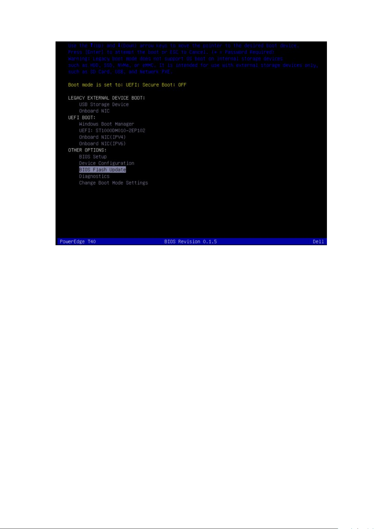
6. The system will boot to a Diag C:\> prompt.
7. Run the file by typing the full filename e.g. O9010A12.exe and press Return.
8. The BIOS Update Utility will load, follow the instructions on screen.
Figure 9. DOS BIOS Update Screen
Updating the Dell BIOS in Linux and Ubuntu environments
If you want to update the system BIOS in a Linux environment such as Ubuntu, see https://www.dell.com/support/article/sln171755/.
Flashing the BIOS from the F12 One-Time boot menu
Updating your system BIOS using a BIOS update .exe file copied to a FAT32 USB key and booting from the F12 one time boot menu.
About this task
BIOS Update
You can run the BIOS update file from Windows using a bootable USB key or you can also update the BIOS from the F12 One-Time boot
menu on the system.
Most Dell systems built after 2012 have this capability and you can confirm by booting your system to the F12 One-Time Boot Menu to see
if BIOS FLASH UPDATE is listed as a boot option for your system. If the option is listed, then the BIOS supports this BIOS update option.
NOTE:
Updating from the One-Time Boot Menu
To update your BIOS from the F12 One-Time boot menu, you will need:
• USB key formatted to the FAT32 file system (key does not have to be bootable)
• BIOS executable file that you downloaded from the Dell Support website and copied to the root of the USB key
• AC power adapter connected to the system
• Functional system battery to flash the BIOS
Perform the following steps to execute the BIOS update flash process from the F12 menu:
Only systems with BIOS Flash Update option in the F12 One-Time Boot Menu can use this function.
CAUTION:
system fail to boot.
Steps
1. From a power off state, insert the USB key where you copied the flash into a USB port of the system .
2. Power on the system and press the F12 key to access the One-Time Boot Menu, Highlight BIOS Flash Update using the arrow keys
then press Enter.
Do not power off the system during the BIOS update process. Powering off the system could make the
Pre-operating system management applications
25
Page 26
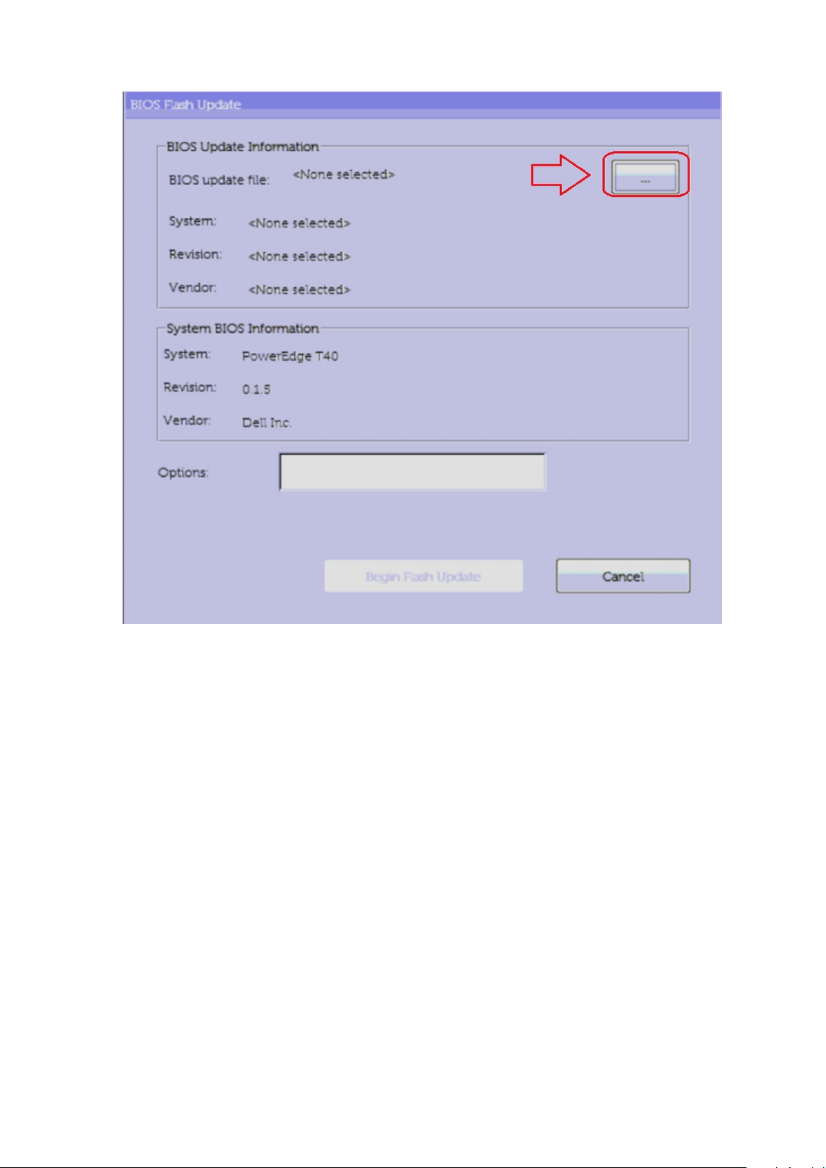
3. The Bios flash menu will open then click the browse button.
26
Pre-operating system management applications
Page 27
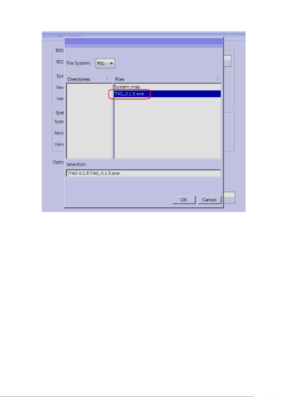
4. The T40_0.1.5.exe file is shown as an example in the following screenshot. The actual file name may vary.
5. Once the file is selected, it will show in the file selection box and you can click the OK button to continue.
Pre-operating system management applications
27
Page 28
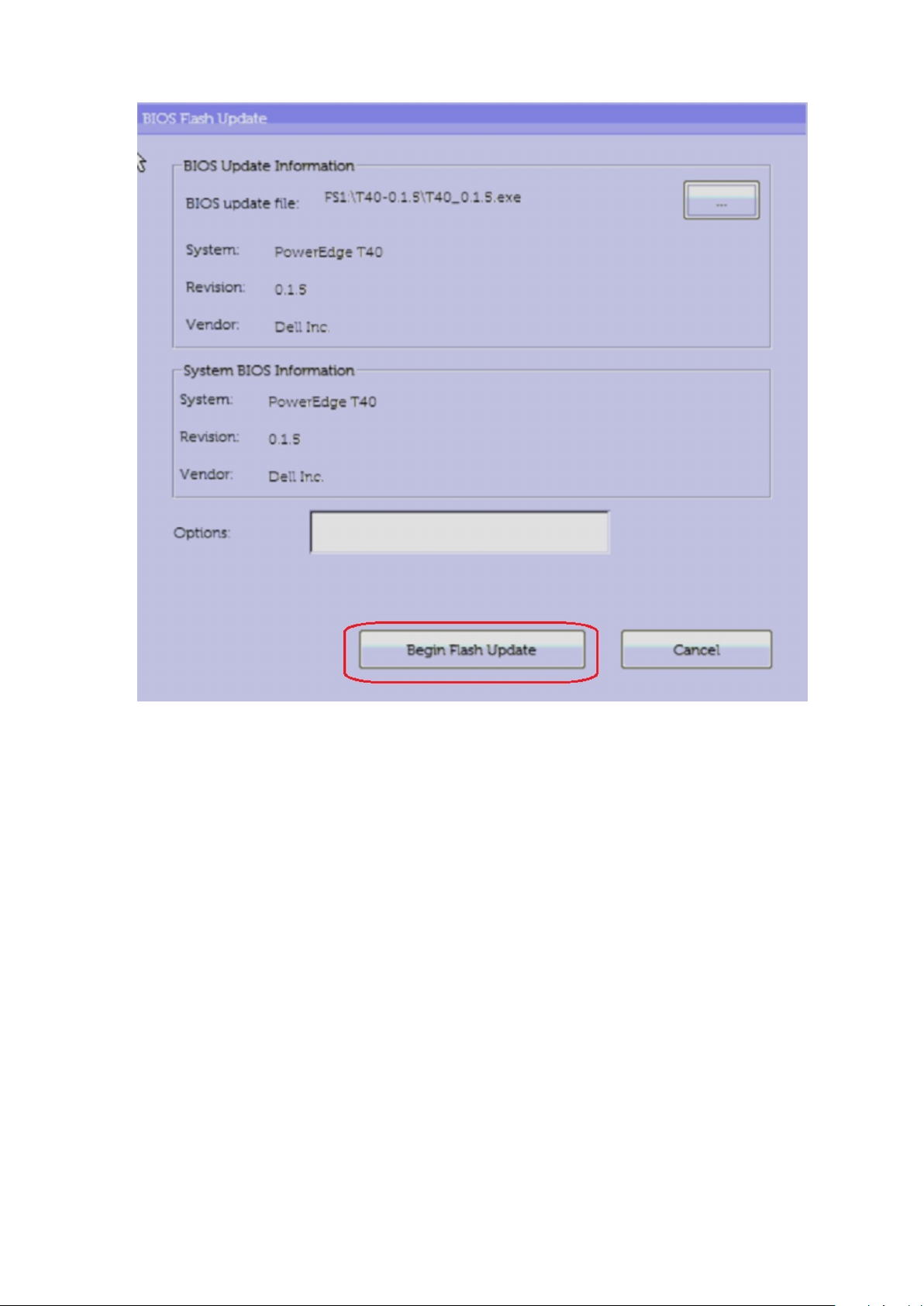
6. Click the Begin Flash Update button.
28
Pre-operating system management applications
Page 29
7. A warning box is displayed asking you if you want to proceed. Click the Yes button to begin the flash.
8. At this point the BIOS flash will execute, the system will reboot and then the BIOS flash will start and a progress bar will show the
progress of the flash. Depending on the changes included in the update, the progress bar may go from zero to 100 multiple times and
the flash process could take as long as 10 minutes. Generally this process takes two to three minutes.
Pre-operating system management applications
29
Page 30

9. Once complete, the system will reboot and the BIOS update process is completed.
System and setup password
Table 16. System and setup password
Password type Description
System password Password that you must enter to log on to your system.
Setup password Password that you must enter to access and make changes to the
BIOS settings of your system.
You can create a system password and a setup password to secure your system.
CAUTION:
CAUTION: Anyone can access the data stored on your system if it is not locked and left unattended.
NOTE: System and setup password feature is disabled.
30 Pre-operating system management applications
The password features provide a basic level of security for the data on your system.
Page 31

Assigning a system setup password
Prerequisites
To assign a System or Admin Password, the status must be Not Set.
About this task
To enter the system setup, press F2 immediately after a power-on or re-boot.
Steps
1. In the System BIOS or System Setup screen, select Security and press Enter.
The Security screen is displayed.
2. Select System/Admin Password and create a password in the Enter the new password field.
Use the following guidelines to assign the system password:
• A password can have up to 32 characters.
• The password can contain the numbers 0 through 9.
• Only lower case letters are valid, upper case letters are not allowed.
• Only the following special characters are allowed: space, (”), (+), (,), (-), (.), (/), (;), ([), (\), (]), (`).
3. Type the system password that you entered earlier in the Confirm new password field and click OK.
4. Press Esc and a message prompts you to save the changes.
5. Press Y to save the changes.
The system reboots.
Deleting or changing an existing system setup password
Prerequisites
Ensure that the Password Status is Unlocked (in the System Setup) before attempting to delete or change the existing System and/or
Setup password. You cannot delete or change an existing System or Setup password, if the Password Status is Locked.
About this task
To enter the System Setup, press F2 immediately after a power-on or reboot.
Steps
1. In the System BIOS or System Setup screen, select System Security and press Enter.
The System Security screen is displayed.
2. In the System Security screen, verify that Password Status is Unlocked.
3. Select System Password, alter or delete the existing system password and press Enter or Tab.
4. Select Setup Password, alter or delete the existing setup password and press Enter or Tab.
NOTE:
the System and/or Setup password, confirm the deletion when prompted.
5. Press Esc and a message prompts you to save the changes.
6. Press Y to save the changes and exit from System Setup.
The system reboot.
If you change the System and/or Setup password, re-enter the new password when prompted. If you delete
PXE boot
You can use the Preboot Execution Environment (PXE) option to boot and configure the networked systems, remotely.
To access the PXE boot option, boot the system and then press F12 during POST instead of using standard Boot Sequence from BIOS
Setup. It does not pull any menu or allows managing of network devices.
Pre-operating system management applications
31
Page 32

Installing and removing system components
Safety instructions
About this task
5
NOTE:
WARNING: Opening or removing the system cover while the system is powered on may expose you to a risk of electric
shock.
CAUTION: Do not operate the system without the cover for a duration exceeding five minutes. Operating the system
without the system cover can result in component damage.
CAUTION: Many repairs may only be done by a certified service technician. You should only perform troubleshooting and
simple repairs as authorized in your product documentation, or as directed by the online or telephone service and
support team. Damage due to servicing that is not authorized by Dell is not covered by your warranty. Read and follow
the safety instructions that came with the product.
CAUTION: To ensure proper operation and cooling, all bays in the system must be always populated with a component or
a blank.
NOTE: It is recommended that you always use an antistatic mat to place the system. components and antistatic strap
that is connected to a grounded work bench while working on the components inside the system
To avoid injury, do not attempt to lift the system by yourself.
Before working inside your system
Prerequisites
Follow the safety guidelines listed in Safety instructions.
Steps
1. Power off the system and attached peripherals.
2. Disconnect the system from the electrical outlet, and disconnect the peripherals.
3. Remove the system cover
4. Lay the system on its side.
After working inside your system
Prerequisites
Follow the safety guidelines listed in Safety instructions.
Steps
1. Install the system cover.
2. Place the system upright on a flat, stable surface.
3. Reconnect the peripherals and connect the system to the electrical outlet.
4. Power on the attached peripherals and then power on the system.
32 Installing and removing system components
Page 33

Recommended tools
You need the following tools to perform the removal and installation procedures:
• Phillips #1 screwdriver
• Phillips #2 screwdriver
• Torx #T15 screwdriver
• 5mm hex nut screwdriver
• Plastic scribe
• Wrist grounding strap connected to the ground
• ESD mat
System cover
Removing the system cover
Prerequisites
1. Follow the safety guidelines listed in Safety instructions.
Steps
1. Pull the system cover release latch.
2. Remove the system cover.
Installing and removing system components
33
Page 34

Figure 10. Removing system cover
Next steps
1. Replace the system cover.
Installing the system cover
Prerequisites
1. Follow the safety guidelines listed in Safety instructions.
Steps
1. Align the tabs on the system cover with the slots on the chassis.
2. Press the system cover until it clicks into place.
34
Installing and removing system components
Page 35

Figure 11. Installing the system cover
Next steps
1. Reconnect the peripherals and connect the system to an electrical outlet.
2. Power on the system, including attached peripherals.
Front bezel
Removing the front bezel
Prerequisites
1. Follow the safety guidelines listed in Safety instructions.
2. Follow the procedure that is listed in Before working inside your system.
Steps
1. Lift the retention clips at the edge of the bezel to release the bezel from the system.
2. Unhook the bezel tabs and pull the bezel away from the system.
Installing and removing system components
35
Page 36

Figure 12. Removing the front bezel
Next steps
1. Replace the front bezel.
Installing the front bezel
Prerequisites
1. Follow the safety guidelines listed in Safety instructions.
2. Follow the procedure that is listed in Before working inside your system.
Steps
1. Place the bezel tabs into the bezel slots in the system.
2. Press the bezel into the system until the retention clips lock into place.
36
Installing and removing system components
Page 37

Figure 13. Installing the front bezel
Next steps
1. Follow the procedure listed in After working inside your system.
Hard drives
Removing a drive carrier from the drive bay
Prerequisites
1. Follow the safety guidelines listed in Safety instructions.
2. Follow the procedure that is listed in Before working inside your system.
3. Using the management software, prepare the drive for removal. Power off the system and unplug the cables before removing the
drive. For more information, see the www.dell.com/storagecontrollermanuals.
4. Disconnect the power and data cables from the drive.
NOTE:
supplied with your operating system.
CAUTION: Mixing drive carriers from previous generations of PowerEdge servers is not supported.
To prevent data loss, ensure that your operating system supports drive installation. See the documentation
Installing and removing system components 37
Page 38

Steps
Press the retention clips and lift the drive carrier out from the drive bay.
Figure 14. Removing the hard drive carrier
Next steps
1. Replace the drive carrier into the drive bay.
Installing a drive carrier into the drive bay
Prerequisites
1. Follow the safety guidelines listed in Safety instructions.
2. Follow the procedure that is listed in Before working inside your system.
Steps
Align and slide the drive carrier into the drive bay until it clicks into place.
38
Installing and removing system components
Page 39

Figure 15. Installing the hard drive carrier
Next steps
1. Connect the power and data cables to the drive.
2. Follow the procedure that is listed in After working inside your system.
NOTE:
NOTE: "SATA 1" is for the first drive. "SATA 2" is for the ODD. "SATA 3" is for the 2nd drive. "SATA 4" is for the 3rd
drive.
SATA ports on the system board are corresponding to SATA devices. Please refer to System Information Label.
Removing a drive from the drive carrier
Prerequisites
1. Follow the safety guidelines listed in Safety instructions.
2. Follow the procedure that is listed in Before working inside your system.
3. Remove the drive carrier from the drive bay.
Steps
1. Flex the drive bracket outwards to release the metal studs on the drive bracket from the holes on the drive.
2. Remove the drive from the carrier.
Installing and removing system components
39
Page 40

Figure 16. Removing the drive from the drive carrier
Next steps
1. Install the drive into the drive carrier.
Installing a drive into the drive carrier
Prerequisites
1. Follow the safety guidelines listed in Safety instructions.
2. Follow the procedure that is listed in Before working inside your system.
Steps
1. Align the screw holes on one side of the drive with the pins on the drive carrier.
2. Flex the drive bracket outward, and align the metal studs on the drive bracket to the holes on the drive and place the drive into the
drive carrier.
40
Installing and removing system components
Page 41

Figure 17. Installing a drive into the drive carrier
Next steps
1. Install a 3.5-drive carrier into the drive bay.
2. Follow the procedure that is listed in After working inside your system.
PSU assembly
Opening the PSU assembly
Prerequisites
1. Follow the safety guidelines listed in Safety instructions.
2. Follow the procedure listed in Before working inside your system.
Steps
1. Slide the PSU assembly release latches to the unlock position.
2. Lift the PSU assembly.
Installing and removing system components
41
Page 42

Figure 18. Opening the PSU assembly
Next steps
Close the PSU assembly.
Closing the PSU assembly
Prerequisites
1. Follow the safety guidelines listed in Safety instructions.
2. Follow the procedure listed in Before working inside your system.
Steps
1. Lower the PSU assembly until the PSU assembly is firmly seated.
2. Slide the PSU assembly release latches to the lock position.
42
Installing and removing system components
Page 43

Figure 19. Closing the PSU assembly
Next steps
1. Follow the procedure that is listed in After working inside your system.
Power supply unit
Removing the power supply unit
Prerequisites
1. Follow the safety guidelines listed in Safety instructions.
2. Follow the procedure that is listed in Before working inside your system.
3. Disconnect the PSU cable from the drive.
4. Open the PSU assembly.
5. Disconnect the PSU cables from the optical drive and the system board.
NOTE:
6. Close the PSU assembly.
Steps
1. Remove the screws securing the PSU support bracket to the PSU assembly and remove the PSU support bracket from the chassis.
2. Remove the screws securing the PSU to the PSU assembly.
a. Slide and remove the PSU from of the chassis.
Observe the routing of the cable as you remove it from the system.
Installing and removing system components
43
Page 44

Figure 20. Removing power supply unit
Next steps
1. Replace the PSU.
Installing the power supply unit
Prerequisites
1. Follow the safety guidelines listed in Safety instructions.
2. Follow the procedure listed in Before working inside your system.
Steps
1. Insert the PSU into the PSU assembly and slide it towards the rear of the chassis until it is firmly seated.
a. Tighten the screws to secure the PSU to the chassis.
2. Align and tighten the PSU support bracket to secure in place.
44
Installing and removing system components
Page 45

Figure 21. Installing power supply unit
Next steps
1. Connect the PSU cable to the drive.
2. Open the PSU assembly.
3. Connect the PSU cables to the optical drive and the system board.
NOTE:
4. Close the PSU assembly.
5. Follow the procedure listed in After working inside your system.
Route the cable properly when you replace it to prevent the cable from being pinched or crimped.
Expansion cards
Removing the Expansion card
Prerequisites
1. Follow the safety guidelines listed in Safety instructions.
2. Follow the procedure listed in Before working inside your system.
3. Open the PSU assembly.
4. If applicable, disconnect the cables connected to the expansion card.
Steps
1. Push the ejector on the expansion card slot to release the expansion card.
2. Holding the card by its edge, pull the card to disengage it from the connector on the system board.
3. Remove the expansion card from the system.
Figure 22. Removing the expansion card
Installing and removing system components
45
Page 46

4. If you are removing the expansion card permanently, install a filler bracket.
NOTE:
You must install a filler bracket over an empty expansion card slot to maintain Federal Communications Commission
(FCC) certification of the system. The brackets also keep dust and dirt out of the system and aid in proper cooling
and airflow inside the system. The filler bracket is necessary to maintain proper thermal conditions.
Figure 23. Installing the filler bracket
Next steps
1. Replace the expansion card.
46
Installing and removing system components
Page 47

Installing the expansion card
Prerequisites
1. Follow the safety guidelines listed in Safety instructions.
2. Follow the procedure that is listed in Before working inside your system.
Steps
1. Unpack the expansion card and prepare it for installation.
NOTE: For instructions, see the documentation accompanying the card.
2. Remove the expansion card or filler bracket from the expansion card holder.
NOTE: Store this bracket for future use. Filler brackets must be installed in empty expansion-card slots to maintain
FCC certification of the system. The brackets also keep dust and dirt out of the system and aid in proper cooling and
airflow inside the system.
Figure 24. Removing the filler bracket
3. Push the ejector on the expansion card slot to allow the expansion card to be inserted into the socket.
4. Holding the card by its edges, position the card so that the card aligns with the expansion card connector.
5. Insert the card firmly into the expansion card connector until the card is fully seated.
Figure 25. Installing the expansion card
Installing and removing system components
47
Page 48

Next steps
1. If applicable, connect the cables to the expansion card.
2. Close the PSU assembly.
3. Install any device drivers required for the card as described in the documentation for the card.
4. Follow the procedure listed in After working inside your system.
Memory module
System memory guidelines
Your system contains four memory sockets that are organized into two channels. In each channel, the first socket is marked white and the
second socket is marked black.
48
Installing and removing system components
Page 49

Figure 26. Memory socket locations on the system board
Memory channels are organized as follows:
Table 17. Memory channels
Channel 0 Channel 1
Slot A1 and A3 Slot A2 and A4
General memory module installation guidelines
To ensure optimal performance of your system, observe the following general guidelines when configuring your system memory. If your
system's memory configurations fail to observe these guidelines, your system might not boot, stop responding during memory
configuration, or operate with reduced memory.
The memory bus may operate at frequency 2400 MT/s, or 2133 MT/s depending on the following factors:
• System profile selected (for example, Performance Optimized, or Custom [can be run at high speed or lower])
• Maximum supported DIMM speed of the processors
• Maximum supported speed of the DIMMs
NOTE:
The system supports Flexible Memory Configuration, enabling the system to be configured and run in any valid chipset architectural
configuration. The following are the recommended guidelines for installing memory modules:
• All DIMMs must be DDR4.
• RDIMMs and LRDIMMs must not be mixed.
MT/s indicates DIMM speed in MegaTransfers per second.
Installing and removing system components
49
Page 50

• 64 GB LRDIMMs that are DDP (Dual Die Package) LRDIMMs must not be mixed with 128 GB LRDIMMs that are TSV (Through Silicon
Via/3DS) LRDIMMs.
• x4 and x8 DRAM based memory modules can be mixed.
• Up to two RDIMMs can be populated per channel regardless of rank count.
• Up to two LRDIMMs can be populated per channel regardless of rank count.
• A maximum of two different ranked DIMMs can be populated in a channel regardless of rank count.
• If memory modules with different speeds are installed, they operate at the speed of the slowest installed memory modules.
• Populate memory module sockets only if a processor is installed.
• Populate all the sockets with white release tabs first, followed by the black release tabs.
• When mixing memory modules with different capacities, populate the sockets with memory modules with the highest capacity first.
For example, if you want to mix 8 GB and 16 GB memory modules, populate 16 GB memory modules in the sockets with white release
tabs and 8 GB memory modules in the sockets with black release tabs.
• Memory modules of different capacities can be mixed provided other memory population rules are followed.
For example, 8 GB and 16 GB memory modules can be mixed.
• In a dual-processor configuration, the memory configuration for each processor must be identical.
For example, if you populate socket A1 for processor 1, then populate socket B1 for processor 2, and so on.
• Mixing of more than two memory module capacities in a system is not supported.
• Unbalanced memory configurations result in a performance loss so always populate memory channels identically with identical DIMMs
for best performance.
• Populate six identical memory modules per processor (one DIMM per channel) at a time to maximize performance.
• To ensure proper system cooling, memory module blanks must be installed in memory sockets that are not occupied.
Removing a memory module
Prerequisites
WARNING:
edges and avoid touching the components or metallic contacts on the memory module.
CAUTION: To ensure proper system cooling, memory module blanks must be installed in any memory socket that is not
occupied. Remove memory module blanks only if you intend to install memory modules in those sockets.
1. Follow the safety guidelines listed in Safety guidelines.
2. Follow the procedure listed in Before working inside your system.
3. Open the PSU assembly.
Steps
1. Locate the appropriate memory module socket.
CAUTION:
module or metallic contacts.
2. Push the ejectors outward on both ends of the memory module socket to release the memory module from the socket.
3. Lift and remove the memory module from the system.
NOTE:
a memory module blank is similar to that of the memory module.
Allow the memory modules to cool after you power off the system. Handle the memory modules by the card
Handle each memory module only by the card edges, ensuring not to touch the middle of the memory
If you are removing the memory module permanently, install a memory module blank. The procedure to install
50 Installing and removing system components
Page 51

Figure 27. Removing a memory module
Next steps
1. Replace a memory module.
Installing a memory module
Prerequisites
1. Follow the safety guidelines listed in Safety instructions.
2. Follow the procedure that is listed in Before working inside your system.
Steps
1. Locate the appropriate memory module socket.
CAUTION:
module or metallic contacts.
CAUTION: To prevent damage to the memory module or the memory module socket during installation, do not bend
or flex the memory module; insert both ends of the memory module simultaneously.
2. Open the ejectors on the memory module socket outward to allow the memory module to be inserted into the socket.
3. Align the edge connector of the memory module with the alignment key of the memory module socket, and insert the memory module
in the socket.
CAUTION:
module evenly.
Handle each memory module only by the card edges, ensuring not to touch the middle of the memory
Do not apply pressure at the center of the memory module; apply pressure at both ends of the memory
NOTE: The memory module socket has an alignment key that enables you to install the memory module in the socket
in only one orientation.
4. Press the memory module with your thumbs until the socket levers firmly click into place.
Installing and removing system components
51
Page 52

Figure 28. Installing a memory module
Next steps
1. Close the PSU assembly.
2. Follow the procedure listed in After working inside your system.
3. To verify if the memory module has been installed properly, press F2 and navigate to System Setup Main Menu > System BIOS >
Memory Settings . In the Memory Settings screen, the System Memory Size must reflect the updated capacity of the installed
memory. If the value is incorrect, one or more of the memory modules may not be installed properly. Ensure that the memory modules
are firmly seated in the sockets. Run the system memory test in system diagnostics. See
Dell Embedded System Diagnostics.
System battery
Replacing the system battery
Prerequisites
WARNING:
same or equivalent type recommended by the manufacturer. For more information, see the safety information that
shipped with your system.
1. Follow the safety guidelines listed in Safety instructions.
2. Follow the procedure listed in Before working inside your system.
3. If applicable, disconnect the power or data cables from expansion card(s).
There is a danger of a new battery exploding if it is incorrectly installed. Replace the battery only with the
Steps
1. Locate the battery socket. For more information, see the System board jumpers and connectors section.
CAUTION:
removing a battery.
2. Use a plastic scribe to pry out the system battery.
52
Installing and removing system components
To avoid damage to the battery connector, you must firmly support the connector while installing or
Page 53

Figure 29. Removing the system battery
3. To install a new system battery, hold the battery with the positive side facing up and slide it under the securing tabs.
4. Press the battery into the connector until it snaps into place.
Figure 30. Installing the system battery
Next steps
1. If applicable, connect the cables to the expansion card(s).
2. Follow the procedure listed in After working inside your system.
3. While booting, press F2 to enter the System Setup and ensure that the battery is operating properly.
4. Enter the correct time and date in the System Setup Time and Date fields.
5. Exit the System Setup.
Optical drive
Removing the optical drive
Prerequisites
1. Follow the safety guidelines listed in Safety instructions.
2. Follow the procedure listed in Before working inside your system.
3. Open the PSU assembly.
Steps
1. Disconnect the power and data cables from the back of the optical drive.
NOTE:
board and the drive. You must route these cables properly when you replace them to prevent them from being
pinched or crimped.
2. Pull the optical drive release tab to unlock the optical drive.
3. Slide the optical drive out of the system.
Observe the routing of the power and data cable inside the chassis as you remove them from the system
Installing and removing system components
53
Page 54

Figure 31. Removing the optical drive
Next steps
1. Replace the optical drive.
Installing the optical drive
Prerequisites
NOTE:
drives can be connected through USB ports.
1. Follow the safety guidelines listed in Safety instructions.
2. Follow the procedure that is listed in Before working inside your system.
3. Open the PSU assembly.
Steps
1. Align and push the optical drive into the slot until the release tab snaps into place.
2. Connect the power cable and the data cable to the optical drive.
Only slim 9.5-mm SATA DVD-ROM drive or DVD+/-RW drive can be installed in your system. External optical
NOTE:
54 Installing and removing system components
Route the cables properly to prevent them from being pinched or crimped.
Page 55

Figure 32. Installing the optical drive
Next steps
1. Close the PSU assembly.
2. Follow the procedure that is listed in After working inside your system.
NOTE:
NOTE: "SATA 1" is for the first drive. "SATA 2" is for the ODD. "SATA 3" is for the 2nd drive. "SATA 4" is for the 3rd
drive.
SATA ports on the system board are corresponding to SATA devices. Please refer to System Information Label.
Speaker
Removing speaker
Prerequisites
1. Follow the safety guidelines listed in Safety instructions.
2. Follow the procedure listed in Before working inside your system.
3. Open the PSU hinge.
4. Disconnect the speaker cable from the connector on the system board.
NOTE:
Un-route the cable through the retention clips on the system fan base plate and system board.
Installing and removing system components 55
Page 56

Figure 33. Speaker cable routing
Steps
1. Press the release tab to disengage the speaker.
2. Push the speaker to the front of the chassis and remove the speaker from the system.
56
Installing and removing system components
Page 57

Figure 34. Removing speaker
Next steps
1. Replace the speaker.
Installing the speaker
Prerequisites
1. Follow the safety guidelines listed in Safety instructions.
2. Follow the procedure listed in Before working inside your system.
Steps
1. Align and insert the speaker in the slot on the fan base plate until it is firmly seated.
2. Connect the speaker cable to the connector on the system board.
Installing and removing system components
57
Page 58

Figure 35. Installing the speaker
NOTE:
Route the cable through the retention clips on the system fan base plate and system board.
58 Installing and removing system components
Page 59

Figure 36. Speaker cable routing
Next steps
1. Close the PSU hinge.
2. Follow the procedure listed in After working inside your system.
System fan
Removing system fan
Prerequisites
CAUTION:
CAUTION: Never operate your system with the system fan removed. System can overheat and result in shutdown of the
system and loss of data.
1. Follow the safety guidelines listed in Safety instructions.
2. Follow the procedure listed in Before working inside your system.
3. Open the PSU assembly.
4. Remove the speaker.
5. Disconnect the fan power cable from the system board connector.
Do not remove or install the fan by holding the blades.
Installing and removing system components
59
Page 60

Steps
1. Remove the screw that secures the system fan base plate to the chassis.
2. Slide the system fan base plate towards the front of the chassis to release it from the system.
Figure 37. Removing the system fan chassis
3. Unroute the system fan cable from the routing channel on the system fan base plate.
4. Stretch the grommets securing the fan.
5. Pull the fan away from the grommets.
6. Repeat steps 4 and 5 to release the fan from the remaining grommets.
Figure 38. Removing the System fan
60
Installing and removing system components
Page 61

Next steps
1. Replace the system fan.
Installing system fan
Prerequisites
CAUTION: Do not install or remove the system fan holding the fan blades.
1. Follow the safety guidelines listed in Safety instructions.
2. Follow the procedure that is listed in Before working inside your system.
Steps
1. Align the grommets on the system fan base plate with the holes on the system fan frame.
2. Stretch the grommets and push the system fan toward the system fan base plate to secure the system fan in place.
3. Route the system fan cable through the routing channel on the system fan base plate.
Figure 39. Installing system fan
4. Align the system fan base plate with the slots on the chassis.
5. Slide the fan base plate into the slot until it is firmly seated.
6. Tighten the screw to secure the system fan base plate to the chassis.
7. Connect the system fan power cable to the connector on the system board.
Installing and removing system components
61
Page 62

Figure 40. System fan bracket installation
Next steps
1. Install the speaker.
2. Close the PSU assembly.
3. Follow the procedure listed in After working inside your system.
Intrusion switch
Removing intrusion switch
Prerequisites
1. Follow the safety guidelines listed in Safety instructions.
2. Follow the procedure listed in Before working inside your system.
3. Open the PSU assembly.
Steps
1. Disconnect the intrusion switch cable from the connector on the system board.
2. Slide and push the intrusion switch out of the intrusion switch slot on the system.
62
Installing and removing system components
Page 63

Figure 41. Removing intrusion switch
Next steps
Replace the intrusion switch.
Installing intrusion switch
Prerequisites
1. Follow the safety guidelines listed in Safety instructions.
2. Follow the procedure that is listed in Before working inside your system.
Steps
1. Align and slide the intrusion switch into the slot in the system.
2. Connect the intrusion switch cable to the connector on the system board.
3. Route the intrusion switch cable through the cable routing clips.
Figure 42. Installing the intrusion switch
Installing and removing system components
63
Page 64

Next steps
1. Close the PSU assembly.
2. Follow the procedure listed in After working inside your system.
Processor and heatsink
Removing heat sink module
Prerequisites
WARNING: The heat sink may be hot to touch for some time after the system has been powered off. Allow the heat sink
to cool before removing it.
1. Follow the safety guidelines listed in Safety instructions.
2. Follow the safety guidelines listed in Before working inside your system.
3. Open the PSU assembly.
Steps
1. Disconnect the heat sink fan power cable connector from the connector on the system board.
2. Using a Phillips #2 screwdriver, loosen the screws on the heat sink in the order mentioned below:
a) Loosen the first screw three turns.
b) Loosen the screw diagonally opposite to the screw you loosened first.
c) Return to the first screw and loosen it completely.
d) Repeat the procedure for the remaining two screws.
3. Lift the heat sink from the system.
Figure 43. Removing heat sink
Next steps
1. If you are removing a faulty heat sink, replace the heat sink module, if not, remove the processor.
64
Installing and removing system components
Page 65

Removing the processor
Prerequisites
WARNING: The processor may be hot to touch for some time after the system has been powered down. Allow the
processpr to cool before removing it.
CAUTION: The processor is held in its socket under strong pressure. Be aware that the release lever can spring up
suddenly if not firmly held.
NOTE: Only remove the processor if you are replacing the processor or system board. This procedure is not required
when replacing a heat sink module.
1. Follow the safety guidelines listed in Safety instructions.
2. Follow the safety guidelines listed in Before working inside your system.
3. Open the PSU assembly.
4. Remove the heat sink module.
Steps
1. Release the socket lever by pushing the lever down and out from under the tab on the processor shield.
2. Lift the lever until the processor shield is fully open.
CAUTION: Do not touch the processor socket pins, they are fragile and can be permanently damaged. Be careful not
to bend the pins in the processor socket when removing the processor out of the socket.
3. Lift the processor out of the socket.
Figure 44. Removing the processor
Next steps
1. Replace the processor.
Installing the processor
Prerequisites
CAUTION:
necessary to maintain proper thermal conditions.
1. Follow the safety guidelines listed in Safety instructions.
2. Follow the safety guidelines listed in Before working inside your system.
3. Remove the heat sink module.
Steps
1. Align the pin-1 indicator triangle of the processor with the triangle on the socket.
Never remove the heat sink from a processor unless you intend to replace the processor. The heat sink is
Installing and removing system components
65
Page 66

CAUTION: Do not use force to seat the processor. When the processor is positioned correctly, it engages into the
socket at ease.
2. Place the processor in the socket.
3. Close the processor shield by sliding it under the retention screw on the system board.
4. Lower the processor shield lever and push it under the tab to lock the processor shield.
Figure 45. Installing the processor
Next steps
1. Install the Heat sink module.
2. Close the PSU assembly.
3. Follow the procedure that is listed in After working inside your system.
Installing heat sink module
Prerequisites
CAUTION:
necessary to maintain proper thermal conditions.
1. Follow the safety guidelines listed in Safety instructions.
2. Follow the safety guidelines listed in Before working inside your system.
3. If removed, install the processor.
Steps
1. If you are using an existing heat sink, remove the thermal grease from the heat sink by using a clean lint-free cloth.
2. Use the thermal grease syringe included with your processor kit to apply the grease in a quadrilateral design on the top of the
processor.
CAUTION:
the processor socket.
NOTE: The thermal grease syringe is intended for single use only. Dispose the syringe after you use it.
Never remove the heat sink from a processor unless you intend to replace the processor. The heat sink is
Applying too much thermal grease can result in excess grease coming in contact with and contaminating
66 Installing and removing system components
Page 67

Figure 46. Applying thermal grease on top of the processor
3. Align the screws on the heat sink with the standoffs on the system board.
NOTE: Orient the heat sink fan appropriately so that the heat sink fan cable position is closer to the memory
modules.
4. Using the Phillips #2 screwdriver, tighten the screws on the heat sink in the order mentioned below:
a) Tighten the first screw three turns.
b) Tighten the screw diagonally opposite to the screw you loosened first.
c) Return to the first screw and tighten it completely.
d) Repeat the procedure for the remaining two screws.
5. Connect the heat sink assembly cable to the connector on the system board.
NOTE:
Figure 47. Installing Heat sink
Next steps
1. Close the PSU assembly.
Ensure to loop the heat sink fan cable around the heat sink fan screw head
Installing and removing system components
67
Page 68

2. Follow the procedure that is listed in After working inside your system
System board
Removing the system board
Prerequisites
CAUTION: If you are using the Trusted Program Module (TPM) with an encryption key, you may be prompted to create a
recovery key during program or System Setup. Be sure to create and safely store this recovery key. If you replace this
system board, you must supply the recovery key when you restart your system or program before you can access the
encrypted data on your hard drives.
CAUTION: Do not attempt to remove the TPM plug-in module from the system board. After the TPM plug-in module is
installed, it is cryptographically bound to that specific system board. Any attempt to remove an installed TPM plug-in
module breaks the cryptographic binding, and it cannot be reinstalled or installed on another system board.
1. Follow the safety guidelines listed in Safety instructions.
2. Follow the procedure listed in Before working inside your system.
3. Open the PSU assembly.
4. Remove the memory modules.
5. Remove the expansion card if installed.
6. Remove the heat sink module.
7. Remove the processor.
8. Disconnect all cables from the system board.
Steps
1. Using the Phillips #2 screwdriver remove the screws that secure the system board to the chassis.
68
Installing and removing system components
Page 69

Figure 48. Syetm board screw location
2. Remove the screws securing the serial port.
3. Holding the edges of the system board, incline the system board at an angle and lift the system board out of the chassis.
CAUTION:
chassis.
CAUTION: Do not lift the system board by holding a memory module, processor, or other components.
Take care not to damage the system identification button while removing the system board from the
Figure 49. Removing the system board
Installing and removing system components
69
Page 70

Next steps
1. Replace or install the system board.
Installing the system board
Prerequisites
1. Follow the safety guidelines listed in Safety instructions.
2. Follow the procedure that is listed in Before working inside your system.
Steps
1. Unpack the new system board assembly.
NOTE:
NOTE: Ensure to remove the serial port screws from the replacement system board.
CAUTION: Take care not to damage the system identification button while placing the system board into the chassis.
2. Holding the system board by its edges, incline the system board at an angle and align the ports on the system board with the slots on
the system, and lower the system board into the system.
3. Tighten the screws to secure the serial port.
Do not lift the system board by holding a memory module, processor, or other components.
Figure 50. Installing the system board
4. Using the Phillips #2 screwdriver secure the system board to the chassis with screws.
70
Installing and removing system components
Page 71

Figure 51. System board screw location
Next steps
1. Replace the following:
a. Memory modules.
b. Processor.
c. Heat sink module.
d. Expansion card, if installed
2. Reconnect all cables to the system board.
NOTE:
securing bracket.
3. Close the PSU assembly.
4. Follow the procedure listed in After working inside your system.
5. Let the system boot.
6. Ensure that you:
a. Update the BIOS firmware.
b. Enter the system service tag after you install the system board. For more information see Entering the service Tag.
Ensure that the cables inside the system are routed along the chassis wall and secured by using the cable
Entering the System Service Tag by using the Service Menu
Prerequisites
WARNING:
be undone once you apply the changes.
Service Menu only appears once after a new system board is replaced. The setting in Service Menu cannot
Installing and removing system components 71
Page 72

NOTE: Intel Active Management Technology (AMT) is supported only on Intel Xeon processor-based systems.
NOTE: Intel Pentium/Core processor-based systems support Intel Standard Manageability.
This procedure is used to update the service tag after a system board replacement.
Steps
1. Remove the system cover.
a) On the inside of the system cover near the System Information Label, note down the number on the AMT/VPRO QR code label.
2. Install the system cover.
3. Start the system.
NOTE: If the system is powered on, shut the system down and start it up (cold boot).
4. After the system has started up, the Service Menu screen is displayed.
5. Select the number in AMT Options box corresponding to the AMT/VPRO number noted earlier from the system cover.
NOTE: MANAGEABILITY ENGINE (ME) DISABLED and MANAGEABILITY ENGINE (ME) LOCKOUT are not supported
on the PowerEdge T40.
6. Type the service tag information in the Enter Service Tag section.
7. Type the optional asset tag information in the Enter Asset Tag section.
8. Click OK to save the changes and exit.
Entering the system Service Tag by using System Setup
Steps
1. Turn on the system.
2. Press F2 to enter System Setup.
3. Click Service Tag Settings.
4. Enter the Service Tag.
NOTE:
Service Tag. After the Service Tag is entered, it cannot be updated or changed.
5. Click Ok.
You can enter the Service Tag only when the Service Tag field is empty. Ensure that you enter the correct
Control panel
Removing the control panel
Prerequisites
1. Follow the safety guidelines listed in Safety instructions.
2. Follow the procedure listed in Before working inside your system.
3. Disconnect all peripherals that are connected to the control panel.
4. Open the PSU assembly.
5. Remove the front bezel.
6. Remove the optical drive.
Steps
1. Disconnect the cables mentioned below from the system board and unroute the cables from routing guides next to the system board
on the chassis.
a) Control panel audio cable.
b) System board power cable.
c) USB Type-C cable.
72
Installing and removing system components
Page 73

d) USB Type-A cables.
2. Remove the screw that secures the control panel to the chassis.
3. Tilt the control panel and release the tabs from the slots on the chassis.
4. Gently remove the control panel and cables away from the chassis.
Figure 52. Removal of the control panel
Next steps
1. Replace the control panel.
Installing the control panel
Prerequisites
1. Follow the safety guidelines listed in Safety instructions.
2. Follow the procedure that is listed in Before working inside your system.
Steps
1. Insert the cables through the control panel slot on the chassis.
2. Tilt the control panel at an angle and insert it into the control panel slot in the chassis.
3. Using the Phillips #2 screwdriver, tighten the screw to secure the control panel to the chassis.
Installing and removing system components
73
Page 74

Figure 53. Installing the control panel
4. Route the cables through the system clip.
5. Connect the cables mentioned below to the system board.
a) Control panel audio cable.
b) System board power cable.
c) USB Type-C cable.
d) USB Type_A cables.
Next steps
1. Install the optical Drive.
2. Install the front bezel.
3. Close the PSU assembly.
4. Reconnect the disconnected peripherals from the control panel assembly if any.
5. Follow the procedure listed in After working inside your system.
Power button module
Removing power button module
Prerequisites
1. Follow the safety guidelines listed in Safety instructions.
2. Follow the procedure listed in Before working inside your system.
3. Open the PSU assembly.
4. Remove the front bezel.
5. Remove the optical drive.
6. Remove the control panel.
Steps
1. Disconnect the power button module cable from the connector on the system board.
2. Remove the power button module cable from the routing guides on the chassis.
3. Remove the adhesive tape that secures the power button module to the chassis.
4. Press the latches on the sides of the power button module and remove it from the chassis.
74
Installing and removing system components
Page 75

Figure 54. Removing the power button module
Next steps
1. Replace the power button module.
Installing power button module
Prerequisites
1. Follow the safety guidelines listed in Safety instructions.
2. Follow the procedure that is listed in Before working inside your system.
Steps
1. Insert the power button module into the power button slot on the chassis.
2. Affix the adhesive tape to secure the power button module to the chassis.
Figure 55. assembly
Installing and removing system components
75
Page 76

3. Route the power button module cable through the routing clips on the chassis.
4. Connect the power button module cable to the connector on the system board.
Next steps
1. Install the control panel.
2. Install the optical Drive.
3. Install the front bezel.
4. Close the PSU hinge.
5. Follow the procedure listed in After working inside your system.
76 Installing and removing system components
Page 77

6
Jumpers and connectors
This topic provides specific information about the jumpers. It also provides some basic information about jumpers and switches and
describes the connectors on the board in the system. Jumpers on the system board help to disable the system and setup passwords. You
must know the connectors on the system board to install components and cables correctly.
Topics:
• System board jumpers and connectors
• System board jumper settings
• Disabling forgotten password
System board jumpers and connectors
Figure 56. System board jumpers and connectors
Jumpers and connectors 77
Page 78

Table 18. System board jumpers and connectors
Item Connector Description
1 ATX_CPU Processor power connector
2 PROCESSOR Processor socket
3 CPU_FAN Processor fan connector
4 SYS FAN 1 System fan connector
5 INTRUDER Intrusion switch connector
6 F_PANEL Power button module connector
7 ATX_POWER System power connector
8 TYPE-C Front panel USB Type-C connector
9 F_USB 1 Front panel USB connector
10 SATA 1 SATA connector 1
11 SATA 2 SATA connector 2
12 SATA 3 SATA connector 3
13 SATA 4 SATA connector 4
14 A3, A1, A4, A2 Memory module sockets
15 CMOS BATTERY CMOS Battery connector
16 PCIE x16 Slot 1 PCIe card connector 1
17 NVRAM_CLR (CMOS_CLR) BIOS setting recover to default jumper
18 PWRD_EN (PW_CLR) Reset BIOS password
19 PCI Slot 2 PCI card connector 2
20 INT SPKR Speaker connector
21 F_AUDIO Audio connector
22 PCIE x4 Slot 4 PCIe card connector 4
23 PCIE x4 Slot 3 PCIe card connector 3
System board jumper settings
The service system board jumper must be set to Password to function normally. As long as the jumper stays at Service Mode, all values
set in BIOS will not be saved and the system will not exit the manufacturing mode with an error prompt indicating that jumpers are
incorrect.
Table 19. System Board Jumper Settings
Jumper Setting Description
PWRD_EN (PW_CLR) The password feature is enabled.
Clears BIOS password.
NVRAM_CLR
(CMOS_CLR)
78 Jumpers and connectors
Real-time clock reset. Can be used for troubleshooting (pins 1 and
2).
Recovers BIOS setting to default.
Page 79

Table 20. System board jumper details
Jumper Function Operation
CO21 PASSWORD_CLR
Short: Default
Open: Clear
P_CMOCLR CMOS_CLR
P_SVRMOD SERVICE_MODE
Short: Clear
Open: Default
1-2 Short: Disable
2-3 Short: Default
Disabling forgotten password
The software security features of the system include a system password and a setup password. The password jumper enables or disables
password features and clears any password(s) currently in use.
Prerequisites
CAUTION: Many repairs may only be done by a certified service technician. Damage due to servicing that is not
authorized by Dell is not covered by your warranty. Read and follow the safety instructions that are shipped with your
product.
Steps
1. Power off the system, including any attached peripherals, and disconnect the system from the electrical outlet.
2. Remove the system cover.
3. Move the jumper (CO21) on the system board jumper to "CLEAR" position.
4. Install the system cover.
The existing passwords are not disabled (erased) until the system boots with the jumper on "CLEAR" position. However, before you
assign a new system and/or setup password, you must move the jumper back to "DEFAULT" position.
NOTE:
the new password(s) the next time it boots.
5. Reconnect the system to its electrical outlet and power on the system, including any attached peripherals.
6. Power off the system, including any attached peripherals, and disconnect the system from the electrical outlet.
7. Remove the system cover.
8. Move the jumper on the system board jumper back to "DEFAULT" position.
9. Install the system cover.
10. Reconnect the system to its electrical outlet and power on the system, including any attached peripherals.
11. Assign a new system and/or setup password.
If you assign a new system and/or setup password with the jumper on "CLEAR" position, the system disables
Jumpers and connectors
79
Page 80

Technical specifications
The technical and environmental specifications of your system are outlined in this section.
Topics:
• Chassis dimensions
• System weight
• Processor specifications
• Supported operating systems
• PSU specifications
• System fan specifications
• System battery specifications
• Expansion card specifications
• Memory specifications
• Storage controller specifications
• Drive specifications
• Ports and connectors specifications
• Video specifications
• Environmental specifications
7
80 Technical specifications
Page 81

Chassis dimensions
Figure 57. Chassis dimensions
Table 21.
X Y Z
176.6 mm
(6.95 inches)
PowerEdge T40 chassis dimensions
335 mm
(13.18 inches)
359.5 mm
(14.15 inches)
System weight
Table 22.
System configuration Maximum weight (with all drives/SSDs)
1x 3.5-inch drive 8.4 Kg (18.52 lb)
PowerEdge T40 system weight
Processor specifications
The PowerEdge T40 system supports the following processors:
Technical specifications
81
Page 82

Table 23. Processor Specifications
Supported processor Model UMA Graphics
Intel Xeon E E series Intel UHD Graphics P630
Intel Core i3 i3-9100 Intel UHD Graphics 630
Intel Pentium Gold G5400 Intel UHD Graphics 610
NOTE: Processor availability is subject to change and may vary by region/country.
Supported operating systems
The PowerEdge T40 supports the following operating systems:
• Microsoft Windows Server 2016
• Microsoft Windows Server 2019
• Ubuntu 18.04 LTS
NOTE:
NOTE: For more information about the specific versions and additions, go to https://www.dell.com/support/home/
Drivers/SupportedOS/poweredge-T40.
For more information, go to www.dell.com/ossupport.
PSU specifications
The PowerEdge T40 system supports one cabled AC power supply unit (PSU).
Table 24. PSU specifications
PSU Class Heat dissipation
(maximum)
300 W AC Bronze 1024 BTU/hr
NOTE: Heat dissipation is calculated by using the PSU wattage rating.
NOTE: The PowerEdge T40 system is also designed to connect to the IT power systems with a phase-to-phase voltage
not exceeding 240 V.
Frequency Voltage Current
50 – 60 Hz
100 – 240 V AC,
autoranging
6A
System fan specifications
The PowerEdge T40 system supports the following:
• One system cooling fan located at the top of the system.
• One processor cooling fan located on the heat sink.
NOTE:
power consumption with the Dell Energy Smart Solution Advisor available at Dell.com/ESSA.
When selecting or upgrading the system configuration, to ensure optimum power utilization, verify the system
System battery specifications
The PowerEdge T40 system supports CR 2032 3.0-V lithium coin cell system battery.
Expansion card specifications
The PowerEdge T40 system supports up to three PCI express (PCIe) Generation 3 and once PCI card.
82
Technical specifications
Page 83

Table 25. Expansion card slots supported on the system board
PCIe slot Slot Type Processor
Slot 1 PCIe x16 Gen3 Processor Full Height Half length
Slot 2
Slot 3
Slot 4
NOTE: The expansion cards are not hot swappable.
PCIe x4 Gen 3 (open ended) Platform Controller
PCIe x4 Gen 3 (open ended) Platform Controller
PCI Platform Controller
Connection
Hub
Hub
Hub
PCIe slot height Maximum Add-in
Full Height
Full Height
Full Height
Card Length
Half length
Half length
Half length
Memory specifications
CAUTION: Dell recommends you to use ECC DIMMs to minimize the risk of uncorrectable system error, data loss and/or
silent data corruption. Non-ECC DIMM is not used for mission-critical applications.
NOTE: Non-ECC DIMMs are supported only in selected countries, for more information contact your sales
representative.
Table 26. Memory specifications
DIMM Type DIMM capacity Minimum RAM Maximum RAM
UDIMM, DDR4, ECC/Non-ECC
8 GB 8 GB 32 GB
16 GB 16 GB 64 GB
Storage controller specifications
The PowerEdge T40 system supports Intel Virtual RAID on CPU (Intel VROC) software RAID.
NOTE:
NOTE: The PowerEdge T40 system does not support RAID 10 as RAID 10 is supported only on systems with 4 drives.
Intel VROC supports RAID modes 0, 1, 5, and 10.
Drive specifications
Drives
The PowerEdge T40 system supports the following drive configurations:
Table 27. Drive configurations
Configuration Capacity
Up to 3 x 3.5-inch drive cabled SATA drives. 1 / 2 / 4 TB
NOTE: The PowerEdge T40 system only supports entry drives.
Entry Drives : Least expensive drives used in applications where low usage and limited total number of drives are applicable. Due to
restrictions on use, these drives are available in a small number of systems and configurations.
Technical specifications
83
Page 84

Optical drives
The PowerEdge T40 system supports the following optical drives.
Table 28. Supported optical drive type
Supported drive type Supported number of drives
Slim 9.5 mm SATA DVD+/-RW drive One
NOTE: External optical drives can be connected through the USB ports.
Ports and connectors specifications
USB ports specifications
The PowerEdge T40 system supports the USB ports mentioned below:
Table 29. PowerEdge T40 system USB specifications
Front Panel Rear Panel
• Two USB 2.0-compliant Type-A ports
• One USB 3.0 Type-A compliant port
• One USB 3.1-compliant Type-C port
• Four USB 3.0 Type-A compliant ports
• Two USB 2.0 Type-A compliant ports
NIC port specifications
The PowerEdge T40 system supports a Network Interface Controller (NIC) port on the back panel, which is available in 10/100/1000
Mbps NIC configurations.
Serial connector specifications
The PowerEdge T40 system supports one serial connector on the back panel, which is a 9-pin connector, Data Terminal Equipment
(DTE), 16550-compliant.
DisplayPort specifications
The PowerEdge T40 system supports two DisplayPorts located on the back panel of the system.
Video specifications
The PowerEdge T40 system supports:
• Intel UHD Graphics P630 for Intel Xeon E processor
• Intel UHD Graphics 630 for Intel Core i3 processor
• Intel UHD Graphics 610 for Intel Pentium Gold processor
Environmental specifications
NOTE:
located with the Manuals & Documents on www.dell.com/support/home.
84 Technical specifications
For additional information about environmental certifications, refer to the
Product Environmental Datasheet
Page 85

Table 30. Temperature specifications
Temperature Specifications
Storage -40–65°C (-40–149°F)
Continuous operation (for altitude less than 900 m
or 2953 ft)
Fresh air T40 do not support Fresh air (Expanded operating temperature)
Maximum temperature gradient (operating and
storage)
Table 31. Relative humidity specifications
Relative humidity Specifications
Storage 5% to 95% RH with 27°C (80.6°F) maximum dew point.
Operating 20% to 80% RH with 21°C ( 69.8 °F ) maximum dew point.
Table 32. Maximum vibration specifications
Maximum vibration Specifications
Operating 0.26 G
Storage 1.88 G
Table 33. Maximum shock pulse specifications
Maximum shock pulse Specifications
Operating Six consecutively executed shock pulses in the positive and negative x, y, and z
10–35°C (50–95°F) with no direct sunlight on the equipment
20°C/h (36°F/h)
Atmosphere must be noncondensing at all times.
at 5 Hz to 350 Hz (all operation orientations)
rms
at 10 Hz to 500 Hz for 15 minutes (all six sides tested)
rms
axis of 6G for up to 11 ms.
Storage Six consecutively executed shock pulses in the positive and negative x, y, and z
axis (one pulse on each side of the system) of 71 G for up to 2 ms.
Table 34. Maximum altitude specifications
Maximum altitude Specifications
Operating 3048 m (10,000 ft)
Storage 12,000 m (39,370 ft)
Table 35. Operating temperature derating specifications
Operating temperature derating Specifications
Up to 35°C (95°F) Maximum temperature is reduced by 1°C/300 m (1°F/547 ft), above 900 m
(2,953 ft).
Thermal restriction matrix
Table 36. Thermal restrictions matrix
Ambient 25°C 30°C 35°C
Processor No restriction No restriction No restriction
DIMM No restriction No restriction No restriction
Drive
Limited to entry drives with power less than 6.8W
Or
No restriction to 1 / 2 TB 7200 rpm and 4 TB 5400 rpm
Technical specifications 85
Page 86

Ambient 25°C 30°C 35°C
NOTE: The PowerEdge T40 does not support enterprise-class drives.
Card
Limited to Tier 2 PCIe cards
Or
PCIe cards do not require system level cooling assistance up to a local ambient temperature of 55°C
Particulate and gaseous contamination specifications
Table 37. Particulate contamination specifications
Particulate contamination Specifications
Air filtration Data center air filtration as defined by ISO Class 8 per ISO 14644-1 with a 95% upper confidence
limit.
NOTE: This condition applies only to data center environments. Air filtration requirements do not apply to IT equipment
designed to be used outside a data center, in environments such as an office or factory floor.
NOTE: Air entering the data center must have MERV11 or MERV13 filtration.
Conductive dust Air must be free of conductive dust, zinc whiskers, or other conductive particles.
NOTE: This condition applies to data center and non-data center environments.
Corrosive dust Air must be free of corrosive dust.
Residual dust present in the air must have a deliquescent point less than 60% relative humidity.
NOTE: This condition applies to data center and non-data center environments.
Table 38. Gaseous contamination specifications
Gaseous contamination Specifications
Copper coupon corrosion rate <300 Å/month per Class G1 as defined by ANSI/ISA71.04-2013
Silver coupon corrosion rate <200 Å/month per Class G1 as defined by ANSI/ISA71.04-2013
NOTE: Maximum corrosive contaminant levels measured at ≤50% relative humidity.
86 Technical specifications
Page 87

System diagnostics and indicator codes
The diagnostic indicators on the system front panel display system status during system startup.
Topics:
• Front panel indicator codes
• NIC indicator codes
• Power supply unit Built-in Self Test
• Enhanced Pre-Boot System Assessment — ePSA diagnostics
• Diagnostics
• Diagnostic error messages
• System error messages
Front panel indicator codes
NOTE: No diagnostic indicators are lit when the system is turned off. To start the system, plug it into a working power
source and press the power button.
Table 39. Front panel indicator codes
8
Icon Description Condition Corrective action
Drive indicator The indicator flashes white if
drives are being accessed.
Power-on indicator The indicator displays solid and
flashing amber if there is a
component failure.
Not applicable.
This is due to component failure
in the system. For more
information, see the Diagnostics
section. If the problem persists,
see the appropriate
Troubleshooting section or the
Getting help section.
System diagnostics and indicator codes 87
Page 88

NIC indicator codes
Each NIC on the back panel has an indicator that provides information about the network activity and link status. The activity LED
indicates whether the NIC is currently connected or not. The link LED indicates the speed of the connected network.
Figure 58. NIC indicators
link indicator 2. activity indicator
1.
Table 40. NIC indicators
Convention Status Condition
A Link and activity indicators are off The NIC is not connected to the network.
B Link indicator is green The NIC is connected to a valid network at 10 Mbps or 100
Mbps port speed.
C Link indicator is orange The NIC is connected to a valid network at 1000 Mbps port
speed.
D Activity indicator is flashing yellow Network data is being sent or received.
Power supply unit Built-in Self Test
PowerEdge T40 supports a power supply unit Built-in Self Test (BIST).
Steps
1. Turn off your server.
2. Disconnect the power cord from the power supply unit, and wait for 15 seconds.
3. After 15 seconds, connect the power cord back to the PSU
4. Press the PSU BIST button.
• If the LED turns on and remains on while the BIST button is pressed, it indicates that the power supply unit is functional. Continue
with troubleshooting steps for other devices.
• If the LED does not turn on, it indicates PSU failure.
Steps to confirm that power supply unit is defective
Perform the steps to identify a faulty power supply unit
Steps
1. Disconnect the power cord from the power supply unit.
88
System diagnostics and indicator codes
Page 89

CAUTION: Ensure that you take adequate safety precautions before accessing the components on your server.
2. Disconnect the internal PSU cables from the motherboard and each internal device.
3. Connect the power cord to the PSU
4. Press the PSU BIST button.
• If the LED turns on and remains on while the BIST button is pressed, it indicates that the power-supply unit is functional. Continue
with troubleshooting steps for other devices.
• If the LED does not turn on, it indicates a power-supply unit failure. Replace the power supply unit.
Enhanced Pre-Boot System Assessment — ePSA diagnostics
About this task
The ePSA diagnostics (also known as system diagnostics) performs a complete check of your hardware. The ePSA is embedded with the
BIOS and is launched by the BIOS internally. The embedded system diagnostics provides a set of options for particular devices or device
groups allowing you to:
The ePSA diagnostics can be initiated on one-time boot menu by pressing F12 while powering on the computer.
• Run tests automatically or in an interactive mode.
• Repeat tests.
• Display or save test results.
• Run thorough tests to introduce additional test options to provide extra information about the failed device(s).
• View status messages that inform you if tests are completed successfully.
• View error messages that inform you of problems encountered during testing.
NOTE:
terminal when the diagnostic tests are performed.
Some tests for specific devices require user interaction. Always ensure that you are present at the computer
Running the ePSA Diagnostics
About this task
Invoke diagnostics boot by either of the methods that are suggested below:
Steps
1. Power on the system.
2. As the system boots, press the F12 key when the Dell logo is displayed.
3. In the boot menu screen, use Up/Down arrow key to select the Diagnostics option and then press Enter.
NOTE:
diagnostics starts running the tests on all the detected devices.
4. Press the arrow in the lower-right corner to go to the page listing.
The detected items are listed and tested.
5. To run a diagnostic test on a specific device, press Esc and click Yes to stop the diagnostic test.
6. Select the device from the left pane and click Run Tests.
7. If there are any issues, error codes are displayed.
Note the error code and contact Dell.
The Enhanced Pre-boot System Assessment window displays, listing all devices detected in the system. The
Diagnostics
Power status light: Indicates the power status.
Solid Amber – The system is unable to boot to the operating system. This indicates that the power supply or another device in the
system is failing.
System diagnostics and indicator codes
89
Page 90

Blinking Amber – The system is unable to boot to the operating system. This indicates that the power supply is normal but another
device in the system is failing or not installed properly.
NOTE: To determine the device that is failing, see the light patterns .
Off – System is in hibernation or turned off.
The power status light blinks amber along with beep codes indicating failures.
For example, the power status light blinks amber two times followed by a pause, and then blinks five times followed by a pause. This 2,5
pattern continues until the computer is turned off indicating the Recovery image is not found.
The following table shows different light patterns and what they indicate:
Table 41. Diagnostic LED codes and Beep Codes
LED # of Flashes / Beep
codes
2,1 Faulty system board Faulty system board
2,2 Faulty system board, power supply unit
2,3 Faulty system board, CPU, or DIMMS Faulty system board, power supply unit (PSU), or DIMMS
2,4 Faulty coin cell battery Faulty coin cell battery
2,5 BIOS Recovery AutoRecovery trigger, recovery image is not found or is
2,6 CPU CPU Error
2,7 Memory Memory SPD failure
3,3 Memory No memory detected
3,5 Memory Modules incompatible or invalid configuration
3,6 BIOS Recovery On-demand trigger, recovery image is not found
3,7 BIOS Recovery On-demand trigger, recovery image is invalid
The system may emit a series of beeps during start-up if the errors or problems cannot be displayed. The repetitive beep codes help the
user troubleshoot problems with the system.
Problem description Faults
Faulty system board, power supply unit (PSU), or cabling
(PSU), or cabling
invalid
Diagnostic error messages
Table 42. Diagnostic error messages
Error messages Description
AUXILIARY DEVICE FAILURE
BAD COMMAND OR FILE NAME
CACHE DISABLED DUE TO FAILURE
CD DRIVE CONTROLLER FAILURE
DATA ERROR
DECREASING AVAILABLE MEMORY
DISK C: FAILED INITIALIZATION
90 System diagnostics and indicator codes
The touchpad or external mouse may be faulty. For an external
mouse, check the cable connection. Enable the Pointing Device
option in the System Setup program.
Ensure that you have spelled the command correctly, put spaces in
the proper place, and used the correct path name.
The primary cache internal to the microprocessor has failed.
Contact Dell
The optical drive does not respond to commands from the
computer.
The hard drive cannot read the data.
One or more memory modules may be faulty or improperly seated.
Reinstall the memory modules or, if necessary, replace them.
The hard drive failed initialization. Run the hard drive tests in Dell
Diagnostics.
Page 91

Error messages Description
DRIVE NOT READY
The operation requires a hard drive in the bay before it can
continue. Install a hard drive in the hard drive bay.
ERROR READING PCMCIA CARD
EXTENDED MEMORY SIZE HAS CHANGED
THE FILE BEING COPIED IS TOO LARGE FOR THE
DESTINATION DRIVE
A FILENAME CANNOT CONTAIN ANY OF THE FOLLOWING
CHARACTERS: \ / : * ? " < > | -
GATE A20 FAILURE
GENERAL FAILURE
HARD-DISK DRIVE CONFIGURATION ERROR
HARD-DISK DRIVE CONTROLLER FAILURE 0
The computer cannot identify the ExpressCard. Reinsert the card
or try another card.
The amount of memory recorded in non-volatile memory (NVRAM)
does not match the memory module installed in the computer.
Restart the computer. If the error appears again, Contact Dell
The file that you are trying to copy is too large to fit on the disk, or
the disk is full. Try copying the file to a different disk or use a larger
capacity disk.
Do not use these characters in filenames.
A memory module may be loose. Reinstall the memory module or, if
necessary, replace it.
The operating system is unable to carry out the command. The
message is usually followed by specific information. For example,
Printer out of paper. Take the appropriate
action.
The computer cannot identify the drive type. Shut down the
computer, remove the hard drive, and boot the computer from an
optical drive. Then, shut down the computer, reinstall the hard
drive, and restart the computer. Run the Hard Disk Drive tests in
Dell Diagnostics.
The hard drive does not respond to commands from the computer.
Shut down the computer, remove the hard drive, and boot the
computer from an optical drive. Then, shut down the computer,
reinstall the hard drive, and restart the computer. If the problem
persists, try another drive. Run the
Diagnostics.
Hard Disk Drive tests in Dell
HARD-DISK DRIVE FAILURE
HARD-DISK DRIVE READ FAILURE
INSERT BOOTABLE MEDIA
INVALID CONFIGURATION INFORMATION-PLEASE RUN
SYSTEM SETUP PROGRAM
KEYBOARD CLOCK LINE FAILURE
KEYBOARD CONTROLLER FAILURE
The hard drive does not respond to commands from the computer.
Shut down the computer, remove the hard drive, and boot the
computer from an optical drive. Then, shut down the computer,
reinstall the hard drive, and restart the computer. If the problem
persists, try another drive. Run the
Diagnostics.
The hard drive may be defective. Shut down the computer,
remove the hard drive, and boot the computer from an optical.
Then, shut down the computer, reinstall the hard drive, and restart
the computer. If the problem persists, try another drive. Run the
Hard Disk Drive tests in Dell Diagnostics.
The operating system is trying to boot to non-bootable media, such
as an optical drive. Insert bootable media.
The system configuration information does not match the
hardware configuration. The message is most likely to occur after a
memory module is installed. Correct the appropriate options in the
system setup program.
For external keyboards, check the cable connection. Run the
Keyboard Controller test in Dell Diagnostics.
For external keyboards, check the cable connection. Restart the
computer, and avoid touching the keyboard or the mouse during
the boot routine. Run the Keyboard Controller test in Dell
Diagnostics.
Hard Disk Drive tests in Dell
System diagnostics and indicator codes 91
Page 92

Error messages Description
KEYBOARD DATA LINE FAILURE
For external keyboards, check the cable connection. Run the
Keyboard Controller test in Dell Diagnostics.
KEYBOARD STUCK KEY FAILURE
LICENSED CONTENT IS NOT ACCESSIBLE IN
MEDIADIRECT
MEMORY ADDRESS LINE FAILURE AT ADDRESS, READ
VALUE EXPECTING VALUE
MEMORY ALLOCATION ERROR
MEMORY DOUBLE WORD LOGIC FAILURE AT ADDRESS,
READ VALUE EXPECTING VALUE
MEMORY ODD/EVEN LOGIC FAILURE AT ADDRESS, READ
VALUE EXPECTING VALUE
MEMORY WRITE/READ FAILURE AT ADDRESS, READ
VALUE EXPECTING VALUE
NO BOOT DEVICE AVAILABLE
For external keyboards or keypads, check the cable connection.
Restart the computer, and avoid touching the keyboard or keys
during the boot routine. Run the Stuck Key test in Dell
Diagnostics.
Dell MediaDirect cannot verify the Digital Rights Management
(DRM) restrictions on the file, so the file cannot be played.
A memory module may be faulty or improperly seated. Reinstall the
memory module or, if necessary, replace it.
The software you are attempting to run is conflicting with the
operating system, another program, or a utility. Shut down the
computer, wait for 30 seconds, and then restart it. Run the
program again. If the error message still appears, see the software
documentation.
A memory module may be faulty or improperly seated. Reinstall the
memory module or, if necessary, replace it.
A memory module may be faulty or improperly seated. Reinstall the
memory module or, if necessary, replace it.
A memory module may be faulty or improperly seated. Reinstall the
memory module or, if necessary, replace it.
The computer cannot find the hard drive. If the hard drive is your
boot device, ensure that the drive is installed, properly seated, and
partitioned as a boot device.
NO BOOT SECTOR ON HARD DRIVE
NO TIMER TICK INTERRUPT
NOT ENOUGH MEMORY OR RESOURCES. EXIT SOME
PROGRAMS AND TRY AGAIN
OPERATING SYSTEM NOT FOUND
OPTIONAL ROM BAD CHECKSUM
SECTOR NOT FOUND
SEEK ERROR
SHUTDOWN FAILURE
TIME-OF-DAY CLOCK LOST POWER
The operating system may be corrupted, Contact Dell.
A chip on the system board may be malfunctioning. Run the
System Set tests in Dell Diagnostics.
You have too many programs open. Close all windows and open
the program that you want to use.
Reinstall the operating system. If the problem persists, Contact
Dell.
The optional ROM has failed. Contact Dell.
The operating system cannot locate a sector on the hard drive.
You may have a defective sector or corrupted File Allocation Table
(FAT) on the hard drive. Run the Windows error-checking utility to
check the file structure on the hard drive. See Windows Help and
Support for instructions (click Start > Help and Support). If a
large number of sectors are defective, back up the data (if
possible), and then format the hard drive.
The operating system cannot find a specific track on the hard
drive.
A chip on the system board may be malfunctioning. Run the
System Set tests in Dell Diagnostics. If the message reappears,
Contact Dell.
System configuration settings are corrupted. Connect your
computer to an electrical outlet to charge the battery. If the
problem persists, try to restore the data by entering the System
Setup program, then immediately exit the program. If the message
reappears,
Contact Dell.
TIME-OF-DAY CLOCK STOPPED
92 System diagnostics and indicator codes
The reserve battery that supports the system configuration
settings may require recharging. Connect your computer to an
Page 93

Error messages Description
electrical outlet to charge the battery. If the problem persists,
Contact Dell.
TIME-OF-DAY NOT SET-PLEASE RUN THE SYSTEM
SETUP PROGRAM
TIMER CHIP COUNTER 2 FAILED
UNEXPECTED INTERRUPT IN PROTECTED MODE
X:\ IS NOT ACCESSIBLE. THE DEVICE IS NOT READY
The time or date stored in the system setup program does not
match the system clock. Correct the settings for the Date and
Time options.
A chip on the system board may be malfunctioning. Run the
System Set tests in Dell Diagnostics.
The keyboard controller may be malfunctioning, or a memory
module may be loose. Run the System Memory tests and the
Keyboard Controller test in Dell Diagnostics or Contact Dell.
Insert a disk into the drive and try again.
System error messages
Table 43. System error messages
System message Description
Alert! Previous attempts at booting this
system have failed at checkpoint [nnnn]. For
help in resolving this problem, please note
this checkpoint and contact Dell Technical
Support
CMOS checksum error
CPU fan failure
The computer failed to complete the boot routine three
consecutive times for the same error.
RTC is reset, BIOS Setup default has been loaded.
CPU fan has failed.
System fan failure
Hard-disk drive failure
Keyboard failure
No boot device available
No timer tick interrupt
NOTICE - Hard Drive SELF MONITORING SYSTEM has
reported that a parameter has exceeded its
normal operating range. Dell recommends that
you back up your data regularly. A parameter
out of range may or may not indicate a
potential hard drive problem
System fan has failed.
Possible hard disk drive failure during POST.
Keyboard failure or loose cable. If reseating the cable does not
solve the problem, replace the keyboard.
No bootable partition on hard disk drive, the hard disk drive cable is
loose, or no bootable device exists.
• If the hard drive is your boot device, ensure that the cables are
connected and that the drive is installed properly and
partitioned as a boot device.
• Enter system setup and ensure that the boot sequence
information is correct.
A chip on the system board might be malfunctioning or
motherboard failure.
S.M.A.R.T error, possible hard disk drive failure.
System diagnostics and indicator codes 93
Page 94

Getting help
Topics:
• Recycling or End-of-Life service information
• Uploading files to Dell Technical Support
• Contacting Dell
• Accessing system information by using QRL
Recycling or End-of-Life service information
Take back and recycling services are offered for this product in certain countries. If you want to dispose of system components, visit
www.dell.com/recyclingworldwide and select the relevant country.
Uploading files to Dell Technical Support
If you want to send system reports or other files to Dell Technical Support, you can use the file upload page available on Dell
TechDirect.
The uploaded files are bound to the Service Tag you provide during the process. There is no prior registration needed for usage.
9
NOTE:
NOTE: As a registered Dell TechDirect user you have the ability to attach documents as part of Technical Support or
Self-Dispatch service requests created in the portal.
For more information on how to manually upload files to Dell Technical Support, see manual upload help page.
Uploading a file will not automatically open a Service Request!
Contacting Dell
Dell provides several online and telephone based support and service options. If you do not have an active internet connection, you can
find contact information about your purchase invoice, packing slip, bill, or Dell product catalog. Availability varies by country and product,
and some services may not be available in your area. To contact Dell for sales, technical assistance, or customer service issues:
Steps
1. Go to www.dell.com/support/home
2. Select your country from the drop-down menu on the lower right corner of the page.
3. For customized support:
a) Enter your system Service Tag in the Enter your Service Tag field.
b) Click Submit.
The support page that lists the various support categories is displayed.
4. For general support:
a) Select your product category.
b) Select your product segment.
c) Select your product.
The support page that lists the various support categories is displayed.
5. For contact details of Dell Global Technical Support:
a) Click Global Technical Support
b) The Contact Technical Support page is displayed with details to call, chat, or e-mail the Dell Global Technical Support team.
94 Getting help
Page 95

Accessing system information by using QRL
You can use the Quick Resource Locator (QRL) located on the information tag in the front of the T40, to access the information about
the PowerEdge T40.
Prerequisites
Ensure that your smartphone or tablet has the QR code scanner installed.
The QRL includes the following information about your system:
• How-to videos
• Reference materials, including the Installtion and Service Manual, and mechanical overview
• Your system service tag to quickly access your specific hardware configuration and warranty information
• A direct link to Dell to contact technical assistance and sales teams
Steps
1. Go to www.dell.com/qrl and navigate to your specific product or
2. Use your smartphone or tablet to scan the model-specific Quick Resource (QR) code on your system or in the Quick Resource
Locator section.
Quick Resource Locator for PowerEdge T40 system
Figure 59. Quick Resource Locator for PowerEdge T40 system
Getting help
95
Page 96

Documentation resources
This section provides information about the documentation resources for your system.
To view the document that is listed in the documentation resources table:
• From the Dell EMC support site:
1. Click the documentation link that is provided in the Location column in the table.
2. Click the required product or product version.
NOTE:
3. On the Product Support page, click Manuals & documents.
• Using search engines:
• Type the name and version of the document in the search box.
Table 44. Additional documentation resources for your system
Task Document Location
Setting up your system For information about turning on the system and
To locate the product name and model, see the front of your system.
Dell.com/operatingsystemmanuals
the technical specifications of your system, see the
Getting Started With Your System document that
is shipped with your system.
10
For information about installing the operating
system, see the operating system documentation.
Configuring your system For information about updating drivers and
firmware, see the Methods to download firmware
and drivers section in this document.
Managing your system For information about upgrading your system, Dell
recommends that you download and install the
latest BIOS, driver, and systems management
firmware on your system.
Dell.com/support/drivers
Dell.com/support
96 Documentation resources
 Loading...