

Page 1

Dell™ Dimension™ 900 System
REFERENCE AND
TROUBLESHOOTING GUIDE
www.dell.com
support.dell.com
Page 2

____________________
Information in this document is subject to change without notice.
© 1999–2001 Dell Computer Corporation. All rights reserved.
Reproduction in any manner whatsoever without the written permission of Dell Computer Corporation is strictly forbidden.
Trademarks used in this text: Dell, the DELL logo, Dell Precision, DellWare, Inspiron, Latitude, OptiPlex, and Dimension are trademarks
of Dell Computer Corporation; Intel and Pen ti um are registered trademarks and Celeron and MMX are trademarks of Intel Corporation;
MS-DOS, Microsoft, Windows, and Windows NT are registered trademarks of Microsoft Corporation.
Other trademarks and trade names may be used in this document to refer to either the entities claiming the marks and names or their
products. Dell Computer Corporation disclaims any proprietary interest in trademarks and trade names other than its own.
March 2001 P/N 4870V Rev. A05
Page 3

Safety Instructions
Use the following safety guidelines to help protect your computer system from potential damage and to ensure your own personal safety.
NOTICE: Your computer is designed to work only while upright in the stand
shipped with it. Do not attempt to place the computer flat on a desktop,
and do not set heavy objects, such as a monitor, on top of the computer.
When Using Your Computer System
As you use your computer system, observe the following safety guidelines.
CAUTION: Do not operate your computer system with any cover(s) (including computer covers, bezels, filler brackets, front-panel inserts, and so on)
removed.
• To help avoid damaging your computer, be sure the voltage selection switch on
the power supply is set to match the AC power available at your location:
— 100 volts (V)/50 hertz (Hz) in eastern Japan and 100 V/60 Hz in western Japan
— 115 V/60 Hz in most of North and South America and some Far Eastern coun-
tries such as South Korea and Taiwan
— 230 V/50 Hz in most of Europe, the Middle East, and the Far East
Also be sure your monitor and attached devices are electrically rated to operate
with the AC power available in your location.
• Before working inside the computer, unplug the system to help prevent electric
shock or system board damage. Certain system board components continue to
receive power any time the computer is connected to AC power.
• Before disconnecting a device from the computer, disconnect the power cable to
your computer and then press the power button to help avoid possible damage to
the system board.
• To help prevent electric shock, plug the computer and device power cables into
properly grounded power sources. These cables are equipped with three-prong
plugs to help ensure proper grounding. Do not use adapter plugs or remove the
v
Page 4

grounding prong from a cable. If you must use an extension cable, use a threewire cable with properly grounded plugs.
• To help protect your computer system from sudden, transient increases and
decreases in electrical power, use a surge suppressor, line conditioner, or
uninterruptible power supply (UPS).
• Be sure nothing rests on your computer system’s cables and that the cables are
not located where they can be stepped on or tripped over.
• Do not spill food or liquids on your computer. If the computer gets wet, refer to
“If Your Computer Gets Wet” in Chapter 5.
• Do not push any objects into the openings of your computer. Doing so can cause
fire or electric shock by shorting out interior components.
• Keep your computer away from radiators and heat sources. Also, do not block
cooling vents. Avoid placing loose papers underneath your computer; do not
place your computer in a closed-in wall unit or on a bed, sofa, or rug.
Ergonomic Computing Habits
CAUTION: Improper or prolonged keyboard use may result in injury.
CAUTION: Viewing the monitor screen for extended periods of time may
result in eye strain.
For comfort and efficiency, observe the following ergonomic guidelines when setting
up and using your computer system:
• Position your system so that the monitor and keyboard are directly in front of you
as you work. Special shelves are available (from Dell and other sources) to help
you correctly position your keyboard.
• Set the monitor at a comfort able viewing distance (usually 510 to 610 millimeters
[mm] [20 to 24 inches] from your eyes).
• Make sure the monitor screen is at eye level or slightly lower when you are sitting
in front of the monitor.
• Adjust the tilt of the monitor, its contrast and brightness settings, and the lighting
around you (such as overhead lights, desk lamps, and the curtains or blinds on
nearby windows) to minimize reflections and glare on the monitor screen.
• Use a chair that provides good lower back support.
• Keep your forearms horizontal with your wrists in a neutral, comfortable position
while using the keyboard or mouse.
• Always leave space to rest your hands while using the keyboard or mouse.
• Let your upper arms hang naturally at your sides.
• Sit erect, with your feet resting on the floor and your thighs level.
vi
Page 5
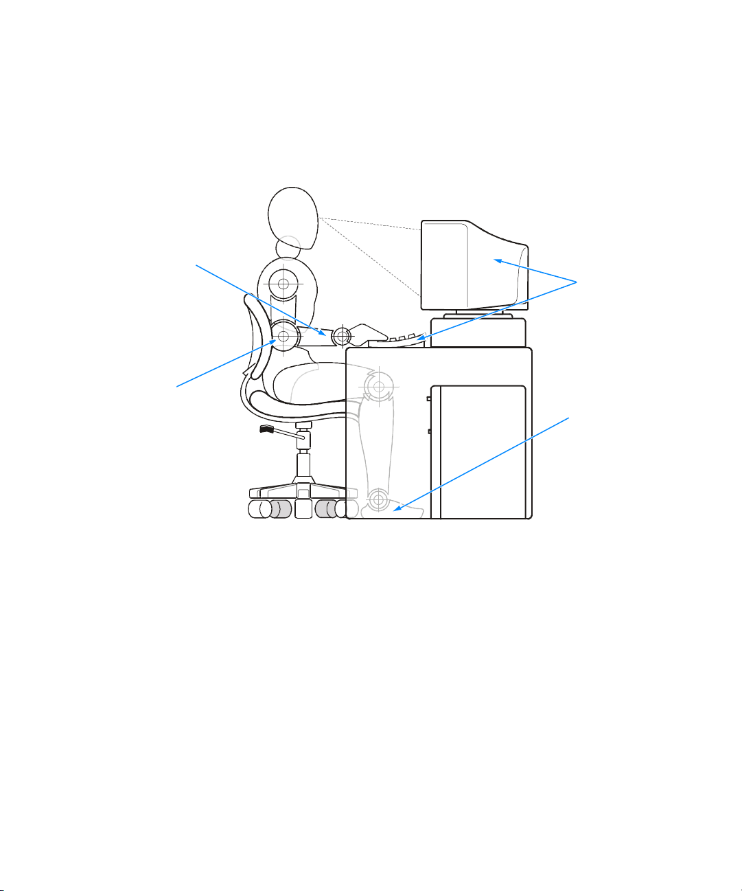
wrists relaxed and flat
arms at desk level
• When sitting, make sure the weight of your legs is on your feet and not on the
front of your chair seat. Adjust your chair’s height or use a footrest, if necessary,
to maintain proper posture.
• Vary your work activities. Try to organize your work so that you do not have to
type for extended periods of time. When you stop typing, try to do things that
use both hands.
monitor screen at or below eye level
monitor and
keyboard
positioned
directly
in front of user
feet flat on the floor
When Working Inside Your Computer
Before you remove the computer cover, perform the following steps in the sequence
indicated.
NOTICE: Do not attempt to service the computer system yourself, except
as explained in this guide and elsewhere in Dell documentation. Always
follow installation and service instructions closely.
1. Turn off your computer and all devices.
2. Ground yourself by touching an unpainted metal surface at the back of the computer before touching anything inside your computer.
While you work, periodically touch an unpainted metal surface on the computer
to dissipate any static electricity that might harm internal components.
vii
Page 6

3. Disconnect any devices connected to the computer, including the monitor, from
their electrical outlets to reduce the potential for personal injury or shock. Also,
disconnect any telephone or telecommunication lines from the computer.
4. Disconnect the power cable to your computer, and then press the power button
to ground the system board.
In addition, take note of these safety guidelines when appropriate:
• When you disconnect a cable, pull on its connector or on its strain-relief loop, not
on the cable itself. Some cables have a connector with locking tabs; if you are disconnecting this type of cable, press in on the locking tabs before disconnecting
the cable. As you pull connectors apart, keep them evenly aligned to avoid bending any connector pins. Also, before you connect a cable, make sure both
connectors are correctly oriented and aligned.
• Handle components and cards with care. Don’t touch the components or con-
tacts on a card. Hold a card by its edges or by its metal mounting bracket.
CAUTION: There is a danger of a new battery exploding if it is incorrectly
installed. Replace the battery only with the same or equivalent type recommended by the manufacturer. Discard used batteries according to the
manufacturer’s instructions.
Protecting Against Electrostatic Discharge
Static electricity can harm delicate components inside your computer. To prevent
static damage, discharge static electricity from your body before you touch any of
your computer’s electronic components, such as the microprocessor. You can do so
by touching an unpainted metal surface on the computer chassis.
viii
As you continue to work inside the computer, periodically touch an unpainted metal
surface to remove any static charge your body may have accumulated.
You can also take the following steps to prevent damage from electrostatic discharge
(ESD):
• When unpacking a static-sensitive component from its shipping carton, do not
remove the component from the antistatic packing material until you are ready to
install the component in your computer. Just before unwrapping the antistatic
packaging, be sure to discharge static electricity from your body.
• When transporting a sensitive component, first place it in an antistatic container
or packaging.
• Handle all sensitive components in a static-safe area. If possible, use antistatic
floor pads and workbench pads.
The following notice may appear throughout this document to remind you of these
precautions:
NOTICE: See “Protecting Against Electrostatic Discharge” in the safety
instructions at the front of this guide.
Page 7

Preface
About This Guide
This guide is intended for anyone who uses a Dell Dimension 900 system. It can be
used by both first-time and experienced computer users who want to learn about the
features and operation of the systems or who want to upgrade their computers. The
chapters and appendixes are summarized as follows:
• Chapter 1, “Introduction,” provides an overview of the system features and infor-
mation on preventive maintenance to protect the computer.
• Chapter 2, “Installing Upgrades on the System Board,” provides information on
performing various upgrades, such as installing additional memory. The chapter
includes a basic orientation to internal features of the computer.
• Chapter 3, “Basic Troubleshooting,” contains checklists to use before calling Dell
for technical assistance.
• Chapter 4, “Software Solutions,” has information on reinstalling software.
• Chapter 5, “Checking Inside Your Computer,” presents troubleshooting proce-
dures for system components such as expansion cards, memory, and drives.
• Chapter 6, “Getting Help,” provides information on obtaining technical assis-
tance. Users who have been unable to resolve problems using the
troubleshooting information provided in this guide can refer to this chapter.
• Appendix A, “System Specifications,” is supplemental reference material.
• Appendix B, “System Setup Program,” describes the system setup program
used for checking and changing system configuration data.
• Appendix C, “Beep Codes and System Messages,” documents status and error
messages generated during system start-up. Included are possible causes and
corrective actions.
• Appendix D, “Regulatory Notices,” provides regulatory information on the system.
Warranty and Return Policy Information
Dell Computer Corporation (“Dell”) manufactures its hardware products from parts
and components that are new or equivalent to new in accordance with industrystandard practices.
ix
Page 8

Other Documents You May Need
NOTE: Information updates are sometimes included with your system to describe
changes to your system or software. Always read these updates before consulting
any other documentation because the updates often contain the latest information.
Besides this Reference and Troubleshooting Guide, the following documentation is
included with your system:
• The Getting Started sheet provides step-by-step instructions for setting up your
computer system.
• The Dell Dimension Systems Setup Guide describes how to properly set up your
operating system and connect a printer.
• The Dell Dimension 900 System Help describes the features and operation of
your computer. It includes tips on using your computer hardware and answers to
commonly asked questions. To open the Help, click the Start button, point to
Programs—> Dell Documents, and then click Dell Dimension Help. You may
also double-click the Dell Documents icon on the Windows desktop, click Sys-
tem Information, click System Documentation, and then click Dell Dimension
Help.
• Online documentation is included for your computer devices (such as a video or
modem card) and for any options you purchase separately from your computer.
To access this supplemental documentation, double-click the Dell Documents
icon on the Windows desktop, click System Information, and then click System
Documentation.
• Operating system documentation.
• Technical information files—sometimes called “readme” files—may be installed
on your hard-disk drive to provide last-minute updates about technical changes to
your system or reference material intended for experienced users.
Notational Conventions
The following subsections describe notational conventions used in this document.
Notes, Notices, and Cautions
Throughout this guide, blocks of text may be accompanied by an icon and printed in
bold type or in italic type. These blocks are notes, notices, and cautions, and they are
used as follows:
NOTE: A NOTE indicates important information that helps you make better use of
your computer system.
NOTICE: A NOTICE indicates either potential damage to hardware or loss
of data and tells you how to avoid the problem.
CAUTION: A CAUTION indicates a potentially hazardous situation which, if
not avoided, may result in minor or moderate injury.
x
Page 9

Typographical Conventions
The following list defines (where appropriate) and illustrates typographical conventions used as visual cues for specific elements of text throughout this document:
• Interface components are window titles, button and icon names, menu names
and selections, and other options that appear on the monitor screen or display.
They are presented in bold.
Example: Click OK.
• Keycaps are labels that appear on the keys on a keyboard. They are enclosed in
angle brackets.
Example: <Enter>
• Key combinations are series of keys to be pressed simultaneously (unless other-
wise indicated) to perform a single function.
Exa mple: <Ctrl><Alt><Enter>
• Commands presented in lowercase bold are for reference purposes only and are
not intended to be typed when referenced.
Example: “Use the format command to . . . .”
In contrast, commands presented in the Courier New font are part of an instruction and intended to be typed.
Example: “Type format a: to format the diskette in drive A.”
• Filenames and directory names are presented in lowercase bold.
Examples: autoexec.bat and c:\windows
• Screen text is a message or text that you are instructed to type as part of a com-
mand (referred to as a command line). Screen text is presented in the Courier
New font.
Example: The following message appears on your screen:
No boot device available
Example: “Type md c:\programs and press <Enter >.”
• Variables are placeholders for which you substitute a value. They are presented in
italics.
Example: DIMM_x (where x represents the DIMM socket designation)
xi
Page 10

xii
Page 11

Contents
Chapter 1 Introduction. . . . . . . . . . . . . . . . . . . . . . . . . . . . . . . . . 1-1
Hardware Features . . . . . . . . . . . . . . . . . . . . . . . . . . . . . . . . . . . . . . . . . . . . . . . . . 1-1
Software Features . . . . . . . . . . . . . . . . . . . . . . . . . . . . . . . . . . . . . . . . . . . . . . . . . . 1-2
Available Upgrades . . . . . . . . . . . . . . . . . . . . . . . . . . . . . . . . . . . . . . . . . . . . . . . . . 1-3
Padlock Ring . . . . . . . . . . . . . . . . . . . . . . . . . . . . . . . . . . . . . . . . . . . . . . . . . . . . . . 1-3
Chapter 2 Installing Upgrades on the System Board . . . . . . . . . 2-1
Safety First—For You and Your Computer . . . . . . . . . . . . . . . . . . . . . . . . . . . . . . . 2-1
Installation Guidelines . . . . . . . . . . . . . . . . . . . . . . . . . . . . . . . . . . . . . . . . . . . . . . . 2-2
Removing and Replacing the Computer Cover . . . . . . . . . . . . . . . . . . . . . . . . . . . . 2-2
Inside Your Computer . . . . . . . . . . . . . . . . . . . . . . . . . . . . . . . . . . . . . . . . . . . . . . . 2-4
System Board . . . . . . . . . . . . . . . . . . . . . . . . . . . . . . . . . . . . . . . . . . . . . . . . . . . . . 2-6
Jumpers . . . . . . . . . . . . . . . . . . . . . . . . . . . . . . . . . . . . . . . . . . . . . . . . . . . . . . 2-8
Password Jumper . . . . . . . . . . . . . . . . . . . . . . . . . . . . . . . . . . . . . . . . . . . 2-8
Processor Mode Jumper. . . . . . . . . . . . . . . . . . . . . . . . . . . . . . . . . . . . . . 2-9
NVRAM Jumper . . . . . . . . . . . . . . . . . . . . . . . . . . . . . . . . . . . . . . . . . . . . 2-9
Boot-Block Select Jumper. . . . . . . . . . . . . . . . . . . . . . . . . . . . . . . . . . . . 2-10
Removing and Replacing the Riser-Board Bracket . . . . . . . . . . . . . . . . . . . . . . . . 2-10
PCI Expansion Card Upgrades . . . . . . . . . . . . . . . . . . . . . . . . . . . . . . . . . . . . . . . 2-12
Installing Expansion Cards . . . . . . . . . . . . . . . . . . . . . . . . . . . . . . . . . . . . . . . 2-13
Removing Expansion Cards . . . . . . . . . . . . . . . . . . . . . . . . . . . . . . . . . . . . . . 2-16
Adding Memory. . . . . . . . . . . . . . . . . . . . . . . . . . . . . . . . . . . . . . . . . . . . . . . . . . . 2-16
Installing a DIMM . . . . . . . . . . . . . . . . . . . . . . . . . . . . . . . . . . . . . . . . . . . . . 2-17
Removing a DIMM . . . . . . . . . . . . . . . . . . . . . . . . . . . . . . . . . . . . . . . . . . . . . 2-18
Replacing the System Battery . . . . . . . . . . . . . . . . . . . . . . . . . . . . . . . . . . . . . . . . 2-19
xiii
Page 12

Chapter 3 Basic Troubleshooting . . . . . . . . . . . . . . . . . . . . . . . . . 3-1
Backing Up Data Files . . . . . . . . . . . . . . . . . . . . . . . . . . . . . . . . . . . . . . . . . . . . . . . 3-1
Installing Additional Hardware and Software . . . . . . . . . . . . . . . . . . . . . . . . . . . . . 3-1
DellWare Support. . . . . . . . . . . . . . . . . . . . . . . . . . . . . . . . . . . . . . . . . . . . . . . 3-2
Checking the Basics . . . . . . . . . . . . . . . . . . . . . . . . . . . . . . . . . . . . . . . . . . . . . . . . 3-2
External Connections . . . . . . . . . . . . . . . . . . . . . . . . . . . . . . . . . . . . . . . . . . . . 3-2
Power. . . . . . . . . . . . . . . . . . . . . . . . . . . . . . . . . . . . . . . . . . . . . . . . . . . . . . . . 3-3
Start-Up Routine . . . . . . . . . . . . . . . . . . . . . . . . . . . . . . . . . . . . . . . . . . . . . . . 3-3
Environmental Factors . . . . . . . . . . . . . . . . . . . . . . . . . . . . . . . . . . . . . . . . . . . 3-4
Monitor . . . . . . . . . . . . . . . . . . . . . . . . . . . . . . . . . . . . . . . . . . . . . . . . . . . . . . 3-4
Speakers . . . . . . . . . . . . . . . . . . . . . . . . . . . . . . . . . . . . . . . . . . . . . . . . . . . . . 3-6
Modem . . . . . . . . . . . . . . . . . . . . . . . . . . . . . . . . . . . . . . . . . . . . . . . . . . . . . . 3-6
Network Cards . . . . . . . . . . . . . . . . . . . . . . . . . . . . . . . . . . . . . . . . . . . . . . . . . 3-7
Diskette Drives . . . . . . . . . . . . . . . . . . . . . . . . . . . . . . . . . . . . . . . . . . . . . . . . 3-8
Optical Drives. . . . . . . . . . . . . . . . . . . . . . . . . . . . . . . . . . . . . . . . . . . . . . . . . . 3-8
Hard-Disk Drives . . . . . . . . . . . . . . . . . . . . . . . . . . . . . . . . . . . . . . . . . . . . . . . 3-9
Running the Dell Diagnostics . . . . . . . . . . . . . . . . . . . . . . . . . . . . . . . . . . . . . . . . . 3-9
Starting the Dell Diagnostics. . . . . . . . . . . . . . . . . . . . . . . . . . . . . . . . . . . . . . . . . 3-10
Dell Diagnostics Main Screen . . . . . . . . . . . . . . . . . . . . . . . . . . . . . . . . . . . . . . . . 3-12
Using the Dell Diagnostics . . . . . . . . . . . . . . . . . . . . . . . . . . . . . . . . . . . . . . . . . . 3-13
Menu . . . . . . . . . . . . . . . . . . . . . . . . . . . . . . . . . . . . . . . . . . . . . . . . . . . . . . . 3-13
Keys . . . . . . . . . . . . . . . . . . . . . . . . . . . . . . . . . . . . . . . . . . . . . . . . . . . . . . . . 3-14
Device Group . . . . . . . . . . . . . . . . . . . . . . . . . . . . . . . . . . . . . . . . . . . . . . . . . 3-14
Device . . . . . . . . . . . . . . . . . . . . . . . . . . . . . . . . . . . . . . . . . . . . . . . . . . . . . . 3-14
Test . . . . . . . . . . . . . . . . . . . . . . . . . . . . . . . . . . . . . . . . . . . . . . . . . . . . . . . . 3-14
Versions . . . . . . . . . . . . . . . . . . . . . . . . . . . . . . . . . . . . . . . . . . . . . . . . . . . . . 3-14
Chapter 4 Software Solutions. . . . . . . . . . . . . . . . . . . . . . . . . . . . 4-1
Using the Power Management Features in Windows 98, Windows Me, and
Windows 2000 . . . . . . . . . . . . . . . . . . . . . . . . . . . . . . . . . . . . . . . . . . . . . . . . . . . . 4-1
Reinstalling Drivers . . . . . . . . . . . . . . . . . . . . . . . . . . . . . . . . . . . . . . . . . . . . . . . . . 4-2
Your System’s Drivers . . . . . . . . . . . . . . . . . . . . . . . . . . . . . . . . . . . . . . . . . . . 4-3
Using the Dell Dimension ResourceCD to Reinstall Drivers . . . . . . . . . . . . . . 4-3
Temporarily Disabling the Virus-Scanning Program . . . . . . . . . . . . . . . . . . . . . . . . 4-4
Resolving Software and Hardware Incompatibilities. . . . . . . . . . . . . . . . . . . . . . . . 4-4
Windows 98 and Windows Me . . . . . . . . . . . . . . . . . . . . . . . . . . . . . . . . 4-4
Windows 2000 . . . . . . . . . . . . . . . . . . . . . . . . . . . . . . . . . . . . . . . . . . . . . 4-5
Windows NT . . . . . . . . . . . . . . . . . . . . . . . . . . . . . . . . . . . . . . . . . . . . . . . 4-6
Reinstalling Windows 98. . . . . . . . . . . . . . . . . . . . . . . . . . . . . . . . . . . . . . . . . . . . . 4-6
Reinstalling Windows Me . . . . . . . . . . . . . . . . . . . . . . . . . . . . . . . . . . . . . . . . . . . . 4-8
Reinstalling Windows 2000. . . . . . . . . . . . . . . . . . . . . . . . . . . . . . . . . . . . . . . . . . . 4-9
xiv
Page 13

Chapter 5 Checking Inside Your Computer . . . . . . . . . . . . . . . . . 5-1
Expansion Cards . . . . . . . . . . . . . . . . . . . . . . . . . . . . . . . . . . . . . . . . . . . . . . . . . . . 5-1
Modem. . . . . . . . . . . . . . . . . . . . . . . . . . . . . . . . . . . . . . . . . . . . . . . . . . . . . . . 5-3
Network Cards . . . . . . . . . . . . . . . . . . . . . . . . . . . . . . . . . . . . . . . . . . . . . . . . . 5-4
System Memory . . . . . . . . . . . . . . . . . . . . . . . . . . . . . . . . . . . . . . . . . . . . . . . . . . . 5-5
Reseating DIMMs . . . . . . . . . . . . . . . . . . . . . . . . . . . . . . . . . . . . . . . . . . . . . . 5-5
If Your Computer Gets Wet. . . . . . . . . . . . . . . . . . . . . . . . . . . . . . . . . . . . . . . . . . . 5-6
If Your Computer Is Damaged. . . . . . . . . . . . . . . . . . . . . . . . . . . . . . . . . . . . . . . . . 5-7
Chapter 6 Getting Help . . . . . . . . . . . . . . . . . . . . . . . . . . . . . . . . 6-1
Technical Assistance . . . . . . . . . . . . . . . . . . . . . . . . . . . . . . . . . . . . . . . . . . . . . . . 6-1
Help Tools . . . . . . . . . . . . . . . . . . . . . . . . . . . . . . . . . . . . . . . . . . . . . . . . . . . . . . . . 6-2
World Wide Web . . . . . . . . . . . . . . . . . . . . . . . . . . . . . . . . . . . . . . . . . . . . . . . 6-2
Automated Order-Status System . . . . . . . . . . . . . . . . . . . . . . . . . . . . . . . . . . . 6-3
Technical Support Service . . . . . . . . . . . . . . . . . . . . . . . . . . . . . . . . . . . . . . . . 6-3
Problems With Your Order . . . . . . . . . . . . . . . . . . . . . . . . . . . . . . . . . . . . . . . . . . . 6-3
Product Information. . . . . . . . . . . . . . . . . . . . . . . . . . . . . . . . . . . . . . . . . . . . . . . . . 6-3
Returning Items for Warranty Repair or Credit . . . . . . . . . . . . . . . . . . . . . . . . . . . . 6-4
Before You Call . . . . . . . . . . . . . . . . . . . . . . . . . . . . . . . . . . . . . . . . . . . . . . . . . . . . 6-4
Dell Contact Numbers . . . . . . . . . . . . . . . . . . . . . . . . . . . . . . . . . . . . . . . . . . . . . . 6-6
Appendix A System Specifications . . . . . . . . . . . . . . . . . . . . . . . . . A-1
Appendix B System Setup Program . . . . . . . . . . . . . . . . . . . . . . . . B-1
Entering the System Setup Program . . . . . . . . . . . . . . . . . . . . . . . . . . . . . . . . . . . B-1
Using the System Setup Program . . . . . . . . . . . . . . . . . . . . . . . . . . . . . . . . . . . . . . B-1
System Setup Screens and Options . . . . . . . . . . . . . . . . . . . . . . . . . . . . . . . . . . . . B-3
Main Screen . . . . . . . . . . . . . . . . . . . . . . . . . . . . . . . . . . . . . . . . . . . . . . . . . . B-4
System Information Screen . . . . . . . . . . . . . . . . . . . . . . . . . . . . . . . . . . . . . . . B-5
Product Information Screen . . . . . . . . . . . . . . . . . . . . . . . . . . . . . . . . . . . . . . B-6
Disk Drives Screen . . . . . . . . . . . . . . . . . . . . . . . . . . . . . . . . . . . . . . . . . . . . . B-7
IDE Primary Channel Master Submenu . . . . . . . . . . . . . . . . . . . . . . . . . . B-8
Onboard Peripherals Screen . . . . . . . . . . . . . . . . . . . . . . . . . . . . . . . . . . . . . . B-9
Boot Options Screen . . . . . . . . . . . . . . . . . . . . . . . . . . . . . . . . . . . . . . . . . . . B-11
Date and Time Screen . . . . . . . . . . . . . . . . . . . . . . . . . . . . . . . . . . . . . . . . . . B-13
System Security Screen . . . . . . . . . . . . . . . . . . . . . . . . . . . . . . . . . . . . . . . . B-14
Advanced Options Screen . . . . . . . . . . . . . . . . . . . . . . . . . . . . . . . . . . . . . . . B-15
Memory/Cache Options Submenu . . . . . . . . . . . . . . . . . . . . . . . . . . . . . B-16
PnP/PCI Options Submenu . . . . . . . . . . . . . . . . . . . . . . . . . . . . . . . . . . . B-17
Disabling a Forgotten Password . . . . . . . . . . . . . . . . . . . . . . . . . . . . . . . . . . . . . . B-18
Clearing NVRAM . . . . . . . . . . . . . . . . . . . . . . . . . . . . . . . . . . . . . . . . . . . . . . . . . . B-19
xv
Page 14

Appendix C Beep Codes and System Messages . . . . . . . . . . . . . . . C-1
POST Beep Codes . . . . . . . . . . . . . . . . . . . . . . . . . . . . . . . . . . . . . . . . . . . . . . . . . C-1
System Messages . . . . . . . . . . . . . . . . . . . . . . . . . . . . . . . . . . . . . . . . . . . . . . . . . C-2
Appendix D Regulatory Notices . . . . . . . . . . . . . . . . . . . . . . . . . . . D-1
VCCI Notice (Japan Only) . . . . . . . . . . . . . . . . . . . . . . . . . . . . . . . . . . . . . . . . . . . . D-2
Class A ITE . . . . . . . . . . . . . . . . . . . . . . . . . . . . . . . . . . . . . . . . . . . . . . . . . . . . D-2
Class B ITE . . . . . . . . . . . . . . . . . . . . . . . . . . . . . . . . . . . . . . . . . . . . . . . . . . . . D-3
Battery Disposal . . . . . . . . . . . . . . . . . . . . . . . . . . . . . . . . . . . . . . . . . . . . . . . . . . . D-3
Index
Figures Figure 1-1. Padlock Ring . . . . . . . . . . . . . . . . . . . . . . . . . . . . . . . . . . . . . . . . . . . 1-4
Figure 2-1. Removing the Computer Cover. . . . . . . . . . . . . . . . . . . . . . . . . . . . . 2-3
Figure 2-2. Removing the Bezel . . . . . . . . . . . . . . . . . . . . . . . . . . . . . . . . . . . . . 2-4
Figure 2-3. Inside the Computer . . . . . . . . . . . . . . . . . . . . . . . . . . . . . . . . . . . . . 2-5
Figure 2-4. System Board Features . . . . . . . . . . . . . . . . . . . . . . . . . . . . . . . . . . . 2-6
Figure 2-5. Removing the Riser-Board Bracket . . . . . . . . . . . . . . . . . . . . . . . . . 2-11
Figure 2-6. PCI Expansion Card . . . . . . . . . . . . . . . . . . . . . . . . . . . . . . . . . . . . . 2-12
Figure 2-7. Riser Board PCI Expansion-Card Connectors . . . . . . . . . . . . . . . . . 2-12
Figure 2-8. Removing the Filler-Bracket Cap . . . . . . . . . . . . . . . . . . . . . . . . . . . 2-14
Figure 2-9. Removing the Filler Bracket . . . . . . . . . . . . . . . . . . . . . . . . . . . . . . 2-14
Figure 2-10. Installing an Expansion Card . . . . . . . . . . . . . . . . . . . . . . . . . . . . . . 2-15
Figure 2-11. Installing a DIMM . . . . . . . . . . . . . . . . . . . . . . . . . . . . . . . . . . . . . . 2-17
Figure 2-12. Removing a DIMM . . . . . . . . . . . . . . . . . . . . . . . . . . . . . . . . . . . . . 2-18
Figure 2-13. Drive Shelf . . . . . . . . . . . . . . . . . . . . . . . . . . . . . . . . . . . . . . . . . . . . 2-20
Figure 2-14. System Battery and Battery Socket . . . . . . . . . . . . . . . . . . . . . . . . 2-21
Figure 3-1. Diagnostics Menu . . . . . . . . . . . . . . . . . . . . . . . . . . . . . . . . . . . . . . 3-12
Figure 3-2. Dell Diagnostics Main Screen . . . . . . . . . . . . . . . . . . . . . . . . . . . . . 3-13
Figure 5-1. Expansion-Card Installation . . . . . . . . . . . . . . . . . . . . . . . . . . . . . . . . 5-2
Figure 5-2. Incorrect Expansion-Card Installations. . . . . . . . . . . . . . . . . . . . . . . . 5-2
Figure 6-1. Diagnostics Checklist . . . . . . . . . . . . . . . . . . . . . . . . . . . . . . . . . . . . 6-5
Figure B-1. Main Screen Menu . . . . . . . . . . . . . . . . . . . . . . . . . . . . . . . . . . . . . . B-4
Figure B-2. System Information Screen Menu . . . . . . . . . . . . . . . . . . . . . . . . . . B-5
Figure B-3. Product Information Screen Menu . . . . . . . . . . . . . . . . . . . . . . . . . . B-6
Figure B-4. Disk Drives Screen Menu . . . . . . . . . . . . . . . . . . . . . . . . . . . . . . . . . B-7
Figure B-5. IDE Primary Channel Master Submenu . . . . . . . . . . . . . . . . . . . . . . . B-8
Figure B-6. Onboard Peripherals Screen Menu . . . . . . . . . . . . . . . . . . . . . . . . . . B-9
Figure B-7. Boot Options Screen Menu. . . . . . . . . . . . . . . . . . . . . . . . . . . . . . . B-11
Figure B-8. Date and Time Screen Menu. . . . . . . . . . . . . . . . . . . . . . . . . . . . . . B-13
Figure B-9. System Security Screen Menu . . . . . . . . . . . . . . . . . . . . . . . . . . . . B-14
Figure B-10. Advanced Options Screen Menu. . . . . . . . . . . . . . . . . . . . . . . . . . . B-15
xvi
Page 15

Figure B-11. Memory/Cache Options Submenu . . . . . . . . . . . . . . . . . . . . . . . . . B-16
Figure B-12. PnP/PCI Options Submenu . . . . . . . . . . . . . . . . . . . . . . . . . . . . . . . B-17
Figure D-1. VCCI Class A ITE Regulatory Mark . . . . . . . . . . . . . . . . . . . . . . . . . . D-3
Figure D-2. VCCI Class B ITE Regulatory Mark . . . . . . . . . . . . . . . . . . . . . . . . . . D-3
Tables Table 2-1. System Board Connectors and Sockets . . . . . . . . . . . . . . . . . . . . . 2-7
Table 2-2. Password Jumper Settings . . . . . . . . . . . . . . . . . . . . . . . . . . . . . . . . 2-8
Table 2-3. Processor Mode Jumper Settings . . . . . . . . . . . . . . . . . . . . . . . . . . 2-9
Table 2-4. NVRAM Jumper Settings . . . . . . . . . . . . . . . . . . . . . . . . . . . . . . . . . 2-9
Table 2-5. Boot-Block Jumper Settings . . . . . . . . . . . . . . . . . . . . . . . . . . . . . . 2-10
Table 3-1. Start-Up Routine Indications . . . . . . . . . . . . . . . . . . . . . . . . . . . . . . . 3-3
Table 6-1. Dell Contact Numbers . . . . . . . . . . . . . . . . . . . . . . . . . . . . . . . . . . . . 6-6
Table A-1. Technical Specifications . . . . . . . . . . . . . . . . . . . . . . . . . . . . . . . . . . A-1
Table B-1. System Setup Navigation Keys . . . . . . . . . . . . . . . . . . . . . . . . . . . . . B-2
Table B-2. Main Screen Menu Options. . . . . . . . . . . . . . . . . . . . . . . . . . . . . . . . B-4
Table B-3. System Information Screen Menu Options . . . . . . . . . . . . . . . . . . . . B-5
Table B-4. Product Information Screen Menu Options. . . . . . . . . . . . . . . . . . . . B-6
Table B-5. Disk Drives Screen Menu Options. . . . . . . . . . . . . . . . . . . . . . . . . . . B-7
Table B-6. IDE Primary Channel Master Submenu Options . . . . . . . . . . . . . . . . B-8
Table B-7. Onboard Peripherals Screen Menu Options . . . . . . . . . . . . . . . . . . . B-9
Table B-8. Boot Options Screen Menu Options . . . . . . . . . . . . . . . . . . . . . . . . B-11
Table B-9. Date and Time Screen Menu Options . . . . . . . . . . . . . . . . . . . . . . . B-13
Table B-10. System Security Screen Menu Options. . . . . . . . . . . . . . . . . . . . . . B-14
Table B-11. Advanced Options Screen Menu Options . . . . . . . . . . . . . . . . . . . . B-15
Table B-12. Memory/Cache Options Submenu Options. . . . . . . . . . . . . . . . . . . B-16
Table B-13. PnP/PCI Options Screen Submenu Options . . . . . . . . . . . . . . . . . . B-17
Table C-1. POST Beep Codes . . . . . . . . . . . . . . . . . . . . . . . . . . . . . . . . . . . . . . . C-1
Table C-2. System Messages . . . . . . . . . . . . . . . . . . . . . . . . . . . . . . . . . . . . . . . C-2
xvii
Page 16

xviii
Page 17

CHAPTER 1
Introduction
Dell™ Dimension™ 900 computer systems are high-speed personal computers that
include an Intel
Instruction, Multiple Data (SIMD) Extensions or a Celeron™ processor with MMX™
technology. These systems incorporate a high-performance Peripheral Component
Interconnect (PCI) design, allowing a wide range of initial configurations and upgrade
possibilities.
This chapter provides information about the following topics:
®
Socket 370 Pentium® III microprocessor with Streaming Single
• Major hardware and software features of your computer
• Available upgrades for your computer
• Theft-deterrent features to protect your computer
Hardware Features
You r De ll computer offers the following hardware features:
• An Intel Socket 370 Pentium III processor with Streaming SIMD Extensions or a
Celeron processor with MMX technology.
The System Information screen in the system setup program lists the speed of
your system’s processor. For information on accessing this application program,
see Appendix B, “System Setup Program.”
• Minimum memory configuration of 64 megabytes (MB) synchronous dynamic
random-access memory (SDRAM). You can increase memory up to 512 MB by
installing 32-, 64-, 128-, or 256-MB SDRAM dual in-line memory modules
(DIMMs) in the two DIMM sockets on the system board.
NOTE: The system memory value reported by the operating system is 1 or 2 MB
less than the memory installed because that memory is reserved for video functions. For example, if the computer has 64 MB of system memory, the operating
system may report 62 or 63 MB.
support.dell.com Introduction 1-1
Page 18

The system board includes the following integrated features:
• Integrated Intel 810e video controller with Dynamic Video Memory and 4 MB of
SDRAM for display cache.
• Supports two one-third–length 32-bit PCI expansion cards for connecting PCI
devices to the PCI bus.
NOTE: PCI expansion-card connector PCI1 (see Figure 2-7) is reserved for use
with Dimension 900 system-specific expansion cards available only from Dell
(see “Available Upgrades,” found later in this chapter). PCI expansion-card connector PCI2 is available for use with any one-third–length commercial PCI card.
• Self-Monitoring and Analysis Reporting Technology II (SMART II) support, which
warns you at system start-up if your hard-disk drive has become unreliable.
Hard-disk drives shipped with these systems are SMART II-compliant.
• Two integrated drive electronics (IDE) interfaces on the PCI bus that support
Advanced Technology Attachment (ATA)-33/66 Ultra direct memory access (DMA)
hard-disk drives and optical drives, such as CD-ROM drives.
NOTE: Inconsistencies in the manufacturing of CD-ROM media may cause some
higher-speed CD-ROM drives to vibrate more than others. Such vibration and
associated noise does not indicate a defect in the drive or the CD.
• Full compliance with PCI specification 2.2.
• Full compliance with Advanced Configuration and Power Interface (ACPI) specifi-
cation 1.0A.
• For systems running the Microsoft
Millennium Edition (Me), or Windows 2000 operating system, the two highperformance Universal Serial Bus (USB) ports provide a single connection point
for multiple USB-compliant devices. You can connect and disconnect these
devices while the system is running. For your convenience, a USB port connector
is located on the front side of the computer and another USB port connector is
located on the back side.
NOTE: If you attach a USB device that was not included in your original system
configuration, you may need to install a specific driver for that device to obtain its
full functionality. Contact the USB device manufacturer for more information.
®
Windows® 98 Second Edition, Windows
• One serial port and one bidirectional parallel port for connecting external devices.
• A Personal System/2 (PS/2)-style keyboard port and a PS/2-compatible mouse
port.
Software Features
The following software is included with your Dell computer system:
• The Microsoft Windows 98 Second Edition, Windows 2000, or Windows Me,
Windows NT
information, see your operating system documentation.
1-2 Dell Dimension 900 System Reference and Troubleshooting Guide
®
4.0 operating system is installed on your hard-disk drive. For more
Page 19

• Virus-scanning software.
• Video drivers designed to support the integrated Intel Direct accelerated graphics
port (AGP) Graphics Accelerator (see “Video Drivers” in Chapter 4 for more information). Before changing the resolution, check the monitor documentation to
determine the supported resolutions and refresh rates.
• Dell Diagnostics for evaluating the computer’s components and devices (see
“Running the Dell Diagnostics” in Chapter 3).
• The system setup program for viewing and changing system configuration infor-
mation (see Appendix B, “System Setup Program”).
Available Upgrades
The upgrades Dell offers undergo rigorous testing to ensure proper operation with
your computer. You should review “PCI Expansion Card Upgrades” in Chapter 2 to be
sure you have the necessary slots or resources available before purchasing such an
upgrade.
Dell offers a variety of expansion cards to increase system functionality:
• Fax/modem card
• 10/10 0–megabit-per-second (Mbps) network card
You can expand your system's memory up to 512 MB by installing additional 168-pin,
100-megahertz (MHz) non-error checking and correction (non-ECC) SDRAM DIMMs in
the DIMM sockets on the system board. Purchasing memory upgrades from Dell
Spare Parts ensures system compatibility; these upgrades are also covered under
your system warranty. See “Adding Memory” in Chapter 2 before purchasing a mem-
ory upgrade.
To order any of these upgrades, call Dell.
Padlock Ring
On the back of the computer is a padlock ring (see Figure 1-1) for attaching commercially available theft-deterrent devices.
support.dell.com Introduction 1-3
Page 20

padlock ring
Figure 1-1. Padlock Ring
The padlock ring allows you to secure the computer cover to the chassis with a padlock to prevent unauthorized access to the inside of the computer. To use the padlock
ring, insert a commercially available padlock through the ring, and then lock the
padlock.
1-4 Dell Dimension 900 System Reference and Troubleshooting Guide
Page 21

CHAPTER 2
Installing Upgrades on the System Board
This chapter describes how to install expansion cards and system memory. It also
tells you how to remove and replace the computer cover and familiarizes you with
internal components.
Safety First—For You and Your Computer
Working inside your computer is safe—if you observe the following precautions.
CAUTION FOR YOUR PERSONAL SAFETY AND PROTECTION OF YOUR
EQUIPMENT
Before working on your computer, perform the following steps:
1. Turn off your computer and all devices.
2. Ground yourself by touching an unpainted metal surface at the back of the
computer before touching anything inside your computer.
While you work, periodically touch an unpainted metal surface on the
computer to dissipate any static electricity that might harm internal
components.
3. Disconnect any devices connected to the computer, including the monitor,
from their electrical outlets to reduce the potential for personal injury or
shock. Also, disconnect any telephone or telecommunication lines from the
computer.
4. Disconnect the power cable to your computer, and then press the power
button to ground the system board.
In addition, Dell recommends that you review the safety instructions at the front of
this guide.
support.dell.com Installing Upgrades on the System Board 2-1
Page 22

Installation Guidelines
Keep a static-sensitive component in its antistatic packing material until you are ready
to install the component in the computer. Just before unwrapping the antistatic packaging, discharge static electricity from your body.
Make sure you have adequate lighting and a clean work space. If you temporarily disconnect cables or remove expansion cards, note the position of the connectors and
slots so that you can reassemble the system correctly. Also note the extra connectors
available for upgrades.
Removing and Replacing the Computer Cover
To remove the computer cover, perform the following steps:
1. Observe the “Caution for Your Personal Safety and Protection of Your Equipment” found earlier in this chapter. Also, observe the safety instructions at the
front of this guide.
NOTICE: To avoid inadvertently damaging the system board, be sure that
you disconnect the computer’s power cable from the electrical outlet and
from the back of the chassis before removing the computer cover. The system board continues to receive a small amount of power when the system
is turned off and attached to an electrical outlet (the system-board power
indicator [see Figure 2-4] is on when power is detected).
2. Lift the computer out of its stand.
3. Place the computer in a horizontal position (see Figure 2-1).
4. If you have installed a padlock through the padlock ring on the back panel, remove
the padlock.
5. Remove the three screws that secure the cover to the back panel (see
Figure 2-1).
2-2 Dell Dimension 900 System Reference and Troubleshooting Guide
Page 23
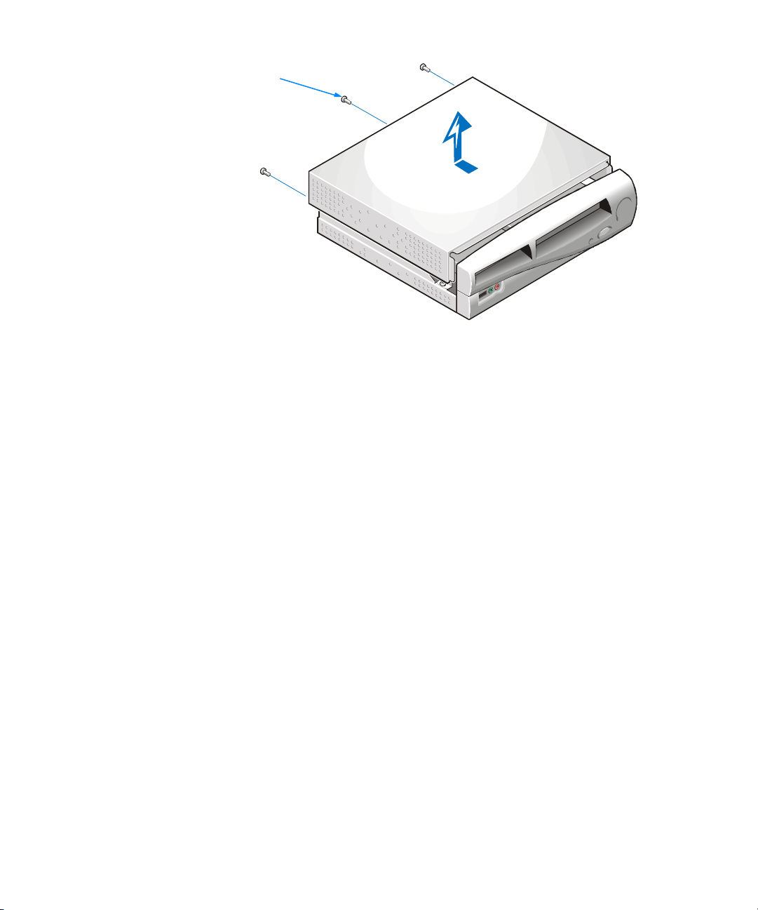
screws (3)
Figure 2-1. Removing the Computer Cover
6. Slide the cover toward the back of the computer about one-half inch.
7. Lift off the cover.
To replace the computer cover, perform the following steps:
1. Check all cable connections, especially those that might have come loose during
your work. Fold cables and unused connectors out of the way so that they do not
catch on the computer cover or interfere with airflow inside the computer.
2. Check to see that no tools or extra parts (including screws) are left inside the
computer.
3. Remove the front bezel by slightly lifting the three bezel tabs (see Figure 2-2) and
gently pulling the bezel away from the front panel.
support.dell.com Installing Upgrades on the System Board 2-3
Page 24

front panel tabs (3)
bezel
Figure 2-2. Removing the Bezel
4. Place the cover on the computer, and slide it toward the front of the computer.
5. Replace the screws that you removed when you removed the computer cover.
6. If you are using a padlock to secure your system, reinstall the padlock.
7. Replace the bezel.
8. Place the computer in its stand.
CAUTION: Your system is designed to work only in a vertical orientation
using the stand shipped with the computer. Do not attempt to operate the
system lying flat on a desktop, and do not set heavy objects such as a
monitor on top of the computer.
Inside Your Computer
Figure 2-3 shows the computer with its cover removed as an aid in locating internal
features and components.
When you look inside your computer, note the DC power cables coming from the
power supply. These cables supply power to the system board and to internal drives.
The flat ribbon cables are the interface cables for internal drives. An interface cable connects a drive to an interface connector on the system board.
The system board—the large printed circuit board secured to the left side of the
chassis—holds the computer’s control circuitry and other electronic components.
Some hardware options are installed directly onto the system board.
2-4 Dell Dimension 900 System Reference and Troubleshooting Guide
Page 25

optical drive
power supply
diskette drive
system board
riser-board
bracket
expansion-card
slots
line-out
connector
USB connector
voltage-select switch
AC power receptacle
mouse connector
Figure 2-3. Inside the Computer
video connector
parallel port connector
serial port connector
keyboard connector
support.dell.com Installing Upgrades on the System Board 2-5
Page 26

System Board
Figure 2-4 shows the system board connectors and sockets, and Table 2-1 describes
their functions.
microprocessor
socket (U9)
keyboard (lower)
and mouse (upper)
connectors (CN1)
parallel port, video,
and serial port
connectors (CN3)
USB port
connector (CN6)
line-out
connector (PH1)
audio signal cable
connector (CN13)
processor
mode jumper (JPX1)
riser-board
connector (SL1)
boot-block
select jumper (JP7)
DIMM sockets (DIMMn)
processor fan
connector (FN1)
NVRAM jumper (JPX2)
jumper (not used)
system board power
indicator (LED1)
password
jumper (JP6)
DC main power input
connector (CN2)
power button connector (JP1)
power-button indicator
connector (JP2)
hard-disk drive activity
indicator connector (JP3)
secondary IDE interface
connector (CN7)
primary IDE interface
connector (CN8)
front audio/USB
board audio signal
cable connector
(CN4)
microphone
connector (CN5)
headphone
connector (CN5)
USB port
connector (CN5)
front audio/USB board interface
connector (CN12)
diskette-drive interface connector (CN16)
battery socket (BT1)
Figure 2-4. System Board Features
2-6 Dell Dimension 900 System Reference and Troubleshooting Guide
Page 27

u
Table 2-1. System Board Connectors and Sockets
Connector or
Socket Description
BT1 Battery socket
CN1 Keyboard and mouse connectors
CN2 DC main power input connector
CN3 Parallel port connector (sometimes referred to as LPT1), video
connector, and serial port connector
CN4 Front audio/USB board audio signal cable connector
CN5 USB port connector, headphone connector, and microphone
connector
CN6 USB port connector
CN7 Secondary IDE interface connector for optical drive
CN8 Primary IDE interface connector
CN12 Front audio/USB board interface connector
CN13 Audio signal cable connector
CN16 Diskette-drive interface connector
DIMMn DIMM socket
FN1 Processor fan connector
JP1 Power button connector
JP2 Power-button indicator connector
JP3 Hard-disk drive activity indicator connector
JP6 Password jumper
JP7 Boot-block select jumper
JPX1 Processor mode jumper
JPX2 NVRAM jumper
LED1 System board power indicator
PH1 Line-out connector
SL1 Riser-board connector
U9 Microprocessor socket
NOTE: The Glossar y in the system Help defines abbreviations and acronyms.
support.dell.com Installing Upgrades on the System Board 2-7
Page 28
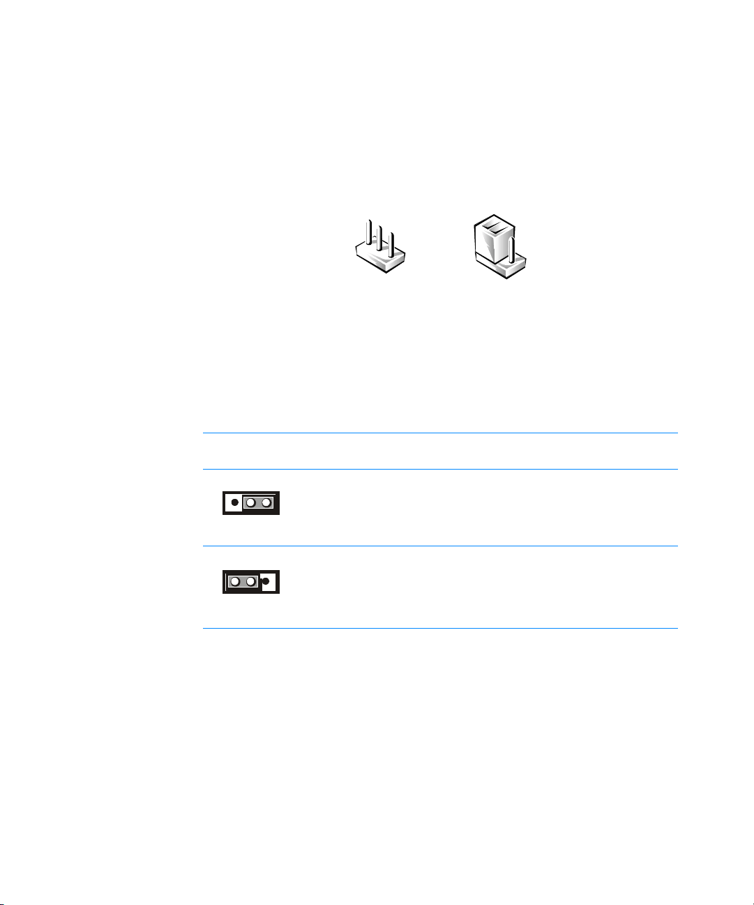
Jumpers
Jumpers are small blocks on the system board with two or more pins emerging from
them. Plastic plugs containing a wire fit down over the pins, creating a circuit. To
change a jumper setting, pull the plug off its pin(s) and carefully fit it down onto the
pin(s) indicated.
NOTICE: Make sure your system is turned off and unplugged from the electrical outlet before you change a jumper setting. Otherwise, damage to
your system or unpredictable results may occur.
Password Jumper
Figure 2-4 shows the location of the password jumper (JP6) in your computer.
Table 2-2 describes the settings and functions of the password jumper.
Table 2-2. Password Jumper Settings
Jumper
Settings Description
Enables system password features (default)
Bypasses system password features
NOTE: The Glossar y in the system Help defines abbreviations and acronyms.
2-8 Dell Dimension 900 System Reference and Troubleshooting Guide
Page 29

Processor Mode Jumper
Figure 2-4 shows the location of the processor mode jumper (JPX1) in your computer.
Table 2-3 describes the settings and functions of the processor mode jumper settings.
Table 2-3. Processor Mode Jumper Settings
Jumper
Settings Description
Enables processor normal mode (default). Change this setting
only if instructed to by Dell Technical Support.
Enables processor safe mode
NOTE: The Glossar y in the system Help defines abbreviations and acronyms.
NVRAM Jumper
Figure 2-4 shows the location of the nonvolatile random-access memory (NVRAM)
jumper (JPX2) in your computer. Table 2-4 describes the settings and functions of the
NVRAM jumper settings.
Table 2-4. NVRAM Jumper Settings
Jumper
Settings Description
Retains current NVRAM settings (default). Change this setting
only if instructed to by Dell Technical Support.
Clears NVRAM
NOTE: The Glossar y in the system Help defines abbreviations and acronyms.
support.dell.com Installing Upgrades on the System Board 2-9
Page 30

Boot-Block Select Jumper
Figure 2-4 shows the location of the boot-block select jumper (JP7) in your computer.
Table 2-5 describes the settings and functions of the boot-block select jumper.
Table 2-5. Boot-Block Jumper Settings
Jumper
Settings Description
Normal boot setting (default). Change this setting only if
instructed to by Dell Technical Support.
Boot from top block setting
NOTE: The Glossar y in the system Help defines abbreviations and acronyms.
Removing and Replacing the Riser-Board Bracket
Certain system board upgrades require that you remove and replace the riser-board
bracket. To remove the riser-board bracket, perform the following steps.
CAUTION: Before you remove the computer cover, see “Safety First—For
You and Your Computer” found earlier in this chapter.
1. Remove the computer cover according to the instructions in “Removing and
Replacing the Computer Cover” found earlier in this chapter.
2. Remove the riser-board screw (see Figure 2-5).
3. Hold the back of the diskette drive with one hand to prevent it from moving as
you perform step 4.
4. Slip one finger into the oval opening on top of the riser-board bracket (see
Figure 2-5). Then slightly lift the back end of the riser-board bracket and gently pull
the riser-board bracket toward the back of the computer until its front tab is free
from the front chassis slot and its two side diskette-drive slots are clear of the
diskette-drive tabs.
CAUTION: When handling the riser board bracket, always hold it by placing a finger through the oval opening in the bracket (see Figure 2-5). Do
not grasp the bracket by its edges, which may be sharp.
2-10 Dell Dimension 900 System Reference and Troubleshooting Guide
Page 31

diskette-drive slots
and tabs (2)
diskette drive
front tab
Figure 2-5. Removing the Riser-Board Bracket
To replace the riser-board bracket, perform the following steps:
riser-board
bracket
riser-board
securing tabs (5)
screw
back tabs (3)
oval opening
1. Hold the back of the diskette drive with one hand to prevent it from moving as
you perform this process.
2. Slip one finger into the oval opening on top of the riser-board bracket (see
Figure 2-5). Then position the riser-board bracket on top of the diskette drive so
that the riser-board securing tabs fit over both sides of the riser board and its
diskette-drive slots align with the diskette-drive tabs (see Figure 2-5).
CAUTION: When handling the riser board bracket, always hold it by placing a finger through the oval opening in the bracket (see Figure 2-5). Do
not grasp the bracket by its edges, which may be sharp.
3. Gently push the riser-board bracket toward the front of the computer until its
three back tabs fit into the three slots on the back of the chassis.
4. Replace the riser-board screw (see Figure 2-5).
5. Replace the computer cover according to the instructions in “Removing and
Replacing the Computer Cover” found earlier in this chapter.
support.dell.com Installing Upgrades on the System Board 2-11
Page 32

PCI Expansion Card Upgrades
NOTE: This computer does not support older expansion card technologies, such as
Industry-Standard Architecture (ISA) cards.
The riser board accommodates up to two one-third–length, 32-bit Peripheral Compo-
nent Interconnect (PCI) expansion cards. PCI expansion-card connector 1 (PCI1) is
reserved for use with Dimension 900 system-specific expansion cards available only
from Dell (see “Available Upgrades” in Chapter 1). PCI expansion-card connector 2
(PCI2) is available for use with any one-third–length commercial PCI card.
Figure 2-6 shows a typical one-third–length PCI expansion card. Figure 2-7 shows the
two PCI expansion-card connectors on the riser board.
PCI expansion card
Figure 2-6. PCI Expansion Card
Figure 2-7. Riser Board PCI Expansion-Card Connectors
Make sure that you have a slot available for the type of card you are installing. Also
check the Windows 98, Windows Me, or Windows 2000 Device Manager, or
Windows NT Diagnostics for an available interrupt request (IRQ) line that is supported by the card.
2-12 Dell Dimension 900 System Reference and Troubleshooting Guide
PCI2 connector
PCI1 connector
Page 33

To check for an IRQ line in the Microsoft Windows 98 or Windows Me operating system, perform the following steps:
1. Click the Start button, point to Settings, and click Control Panel.
2. Double-click the System icon.
3. Click the Device Manager tab.
4. Double-click the Computer icon to open the Computer Properties window and
view the View Resources tab.
To check for an IRQ line in the Microsoft Windows 2000 operating system, perform
the following steps:
1. Click the Start button, point to Settings, and click Control Panel.
2. Double-click the System icon.
3. Click the Hardware tab.
4. Click Device Manager.
5. Click View, and then click Resources by connection.
6. Double-click Interrupt request (IRQ) to view the IRQ assignments.
To check for an IRQ line in the Microsoft Windows NT operating system, start the
Windows NT Diagnostics in the Administrative To o l s (Common) folder and view
the Resources tab.
NOTE: If an IRQ supported by your card is not available, try reassigning resources
used by other devices or disabling unused devices.
Installing Expansion Cards
1. Prepare the expansion card for installation as instructed in the documentation
that came with the expansion card.
Check the documentation to make sure the card is configured to work with other
devices already installed in your computer.
2. Remove the computer cover according to the instructions in “Removing and
Replacing the Computer Cover” found earlier in this chapter.
3. Remove the riser-board bracket according to the instructions in “Removing and
Replacing the Riser-Board Bracket” found earlier in this chapter.
4. Choose an expansion-card connector for the card.
NOTE: The PCI1 connector (see Figure 2-7) is reserved for use with
Dimension 900 system-specific expansion cards available only from Dell (see
“Available Upgrades” in Chapter 1). The PCI2 connector is available for use with
any one-third–length commercial PCI card.
support.dell.com Installing Upgrades on the System Board 2-13
Page 34

5. Remove the screw that secures the filler-bracket cap to the back panel of the
computer (see Figure 2-8), and remove the filler-bracket cap.
filler-bracket cap
screw
Figure 2-8. Removing the Filler-Bracket Cap
6. Unscrew and remove the metal filler bracket that covers the card-slot opening for
the expansion slot you intend to use (see Figure 2-9).
Figure 2-9. Removing the Filler Bracket
2-14 Dell Dimension 900 System Reference and Troubleshooting Guide
filler bracket
Page 35

NOTICE: Use one hand to support the riser board while installing an
expansion card into an expansion-card connector. Otherwise, damage to
the riser-board connector or system board may occur.
7. Insert the expansion card firmly into the expansion-card connector.
A cutout in the card-edge connector aligns with a crossbar in the expansion-card
connector. Gently rock the card into the connector until it is fully seated (see
Figure 2-10).
card-edge connector cutout
expansion card
card-edge connector
Figure 2-10. Installing an Expansion Card
expansion-card
connector
riser board
card-mounting
bracket
screw
8. When the card is firmly seated in the connector, secure the card-mounting
bracket (see Figure 2-10) with the screw you removed in step 6.
Make sure that the front of the card-edge connector is completely seated in the
expansion-card connector. The bottom of the card-mounting bracket must be
inside the card-slot opening, and the top of the bracket must be flush against
the bracket mount with the notch aligned with the screw hole in the bracket
mount. “Expansion Cards” in Chapter 5 provides more information on correctly
seating an expansion card.
9. Replace the filler-bracket cap and screw that you removed in step 5.
10. Connect any cables required for the card as described in the documentation that
came with the card.
support.dell.com Installing Upgrades on the System Board 2-15
Page 36

11. Replace the riser-board bracket according to the instructions in “Removing and
Replacing the Riser-Board Bracket” found earlier in this chapter.
12. Replace the computer cover.
13. See the documentation that came with the expansion card for information on
installing any required drivers for your operating system.
Removing Expansion Cards
1. Remove the computer cover according to the instructions in “Removing and
Replacing the Computer Cover” found earlier in this chapter.
2. Remove the riser-board bracket according to the instructions in “Removing and
Replacing the Riser-Board Bracket” found earlier in this chapter.
3. If necessary, disconnect any cables connected to the card.
4. Remove the screw that secures the filler-bracket cap to the back panel of the
computer (see Figure 2-8), and remove the filler-bracket cap.
5. Remove the screw from the card-mounting bracket.
NOTICE: Use one hand to support the riser board while removing an
expansion card from an expansion-card connector. Otherwise, damage to
the riser-board connector or system board may occur.
6. Grasp the card by its top corners, and ease it out of its connector.
7. If you are removing the card permanently, install a metal filler bracket over the
empty card-slot opening in the bracket mount.
NOTE: Installing filler brackets over empty card-slot openings is necessary to
maintain Federal Communications Commission (FCC) certification of the system.
The brackets also keep dust and dirt out of your computer.
8. Replace the filler-bracket cap and screw that you removed in step 4.
9. Replace the riser-board bracket according to the instructions in “Removing and
Replacing the Riser-Board Bracket” found earlier in this chapter.
10. Replace the computer cover, and reconnect your computer and devices to their
electrical outlets and turn them on.
Adding Memory
You can increase memory to a maximum of 512 megabytes (MB) by installing
combinations of 3.3-volt (V) 32-, 64-, 128-, and 256-MB dual in-line memory modules
(DIMMs) in the two DIMM sockets on the system board. This system supports only
non-error checking and correction (non-ECC), 100-megahertz (MHz) DIMMs. Purchasing memory upgrades from Dell Spare Parts ensures system compatibility; these
upgrades are also covered under your system warranty.
2-16 Dell Dimension 900 System Reference and Troubleshooting Guide
Page 37

NOTE: Your computer is designed for peak performance with specific DIMMs that are
validated through rigorous testing. The system may not recognize other synchronous
dynamic random-access memory (SDRAM) DIMMs and may fail power-on self-test
(POST).
Installing a DIMM
1. Remove the computer cover according to the instructions in “Removing and
Replacing the Computer Cover” found earlier in this chapter.
2. Remove the riser-board bracket according to the instructions in “Removing and
Replacing the Riser-Board Bracket” found earlier in this chapter.
3. Remove the expansion cards according to the instructions in “Removing Expansion Cards” found earlier in this chapter.
4. Press outward on the plastic securing clips at each end of the DIMM socket to
release the clips as shown in step 1 of Figure 2-11.
securing
clips (2)
2.
cutouts (2)
1.
3.
Figure 2-11. Installing a DIMM
5. Orient the DIMM so that the cutouts on its edge connector align with the crossbars in the central groove of the socket.
NOTICE: Do not press near the middle of the DIMM. Doing so could break
the module.
6. Insert the DIMM straight down into the socket, making sure that it fits into the
vertical guides at each end of the socket.
Press firmly at each end until the DIMM snaps into place (see step 2 of
Figure 2-11).
If you inserted the DIMM correctly, the securing clips snap into the cutouts at
each end of the DIMM (see step 3 of Figure 2-11).
support.dell.com Installing Upgrades on the System Board 2-17
Page 38

7. Replace the expansion cards, riser-board bracket, and the computer cover, and
reconnect your computer and devices to their electrical outlets and turn them on.
8. To enter the system setup program, restart the computer and press <Del> when
the blue Dell logo screen appears. Verify that the amount displayed for Tot a l
Memory on the System Information screen is correct.
If the memory total is incorrect, turn off the computer, and remove computer
cover, riser-board bracket, and expansion cards. Then reseat the DIMMs in their
sockets, and repeat step 7.
NOTE: The system memory value reported by the operating system is 1 or 2 MB less
than the memory installed because that memory is reserved for video functions. For
example, if the computer has 64 MB of system memory, the operating system may
report 62 or 63 MB.
Removing a DIMM
1. Remove the computer cover according to the instructions in “Removing and
Replacing the Computer Cover” found earlier in this chapter.
2. Remove the riser-board bracket according to the instructions in “Removing and
Replacing the Riser-Board Bracket” found earlier in this chapter.
3. Remove the expansion cards according to the instructions in “Removing Expansion Cards” found earlier in this chapter.
4. Press outward on the plastic securing clips at each end of the DIMM socket until
the DIMM disengages from the socket (see Figure 2-12).
securing clips (2)
Figure 2-12. Removing a DIMM
5. Replace the expansion cards, riser-board bracket, and the computer cover, and
reconnect your computer and devices to their electrical outlets and turn them on.
6. To enter the system setup program, restart the computer system and press
<Del> when the blue Dell logo screen appears. Verify that the amount displayed
for To ta l M e mo r y on the System Information screen is correct.
2-18 Dell Dimension 900 System Reference and Troubleshooting Guide
Page 39

NOTE: The system memory value reported by the operating system is 1 or 2 MB less
than the memory installed because that memory is reserved for video functions. For
example, if the computer has 64 MB of system memory, the operating system may
report 62 or 63 MB.
Replacing the System Battery
A 3.0-V CR2032 coin-cell battery mounted in a system board socket (see Figure 2-4)
maintains system configuration, date, and time information. The battery can last several years.
NOTE: Leave your power strip turned on when the computer is turned off to extend
battery life.
If the battery expires, the computer loses the system configuration information whenever it is disconnected from its electrical outlet. If you have to repeatedly reset this
information after turning on the computer, replace the battery.
To replace the system battery with another CR2032 coin-cell battery, perform the following steps.
CAUTION: There is a danger of a new battery exploding if it is incorrectly
installed. Replace the battery only with the same or equivalent type
recommended by the manufacturer. Discard used batteries according to the
manufacturer’s instructions.
1. Make a copy of the screens in the system setup program.
You will need a written or printed copy of the system configuration information to
restore the correct settings later. See Appendix B, “System Setup Program,” for
instructions.
2. Remove the computer cover according to the instructions in “Removing and
Replacing the Computer Cover” found earlier in this chapter.
3. Remove the riser-board bracket according to the instructions in “Removing and
Replacing the Riser-Board Bracket” found earlier in this chapter.
4. Remove the front bezel by slightly lifting the three bezel tabs (see Figure 2-13),
and gently pulling the bezel away from the front panel.
5. Remove the drive shelf screws, and lift the drive shelf approximately
one-half inch.
The drive shelf is attached to the chassis with two screws—one to the right of
the optical drive and one to the left of the diskette drive as you face the front of
the computer (see Figure 2-13).
support.dell.com Installing Upgrades on the System Board 2-19
Page 40

screws (2)
bezel
drive shelf
bezel t abs (3)
Figure 2-13. Drive Shelf
NOTICE: If you pry out the battery with a blunt object, insert the object
between the battery and the socket. Otherwise, you may damage the system board by prying off the socket or by breaking circuit traces on the
system board.
6. Locate the battery on the system board (see Figure 2-4), and pry it out of its
socket with your fingers or with a blunt, nonconductive object, such as a plastic
screwdriver.
NOTICE: Inserting the battery upside-down will damage the system board
circuitry.
7. Insert the battery into the socket with the side labeled “+” facing up (see
Figure 2-14).
2-20 Dell Dimension 900 System Reference and Troubleshooting Guide
Page 41

battery
battery socket
(BT1)
Figure 2-14. System Battery and Battery Socket
8. Lower the drive shelf and replace the two screws that you removed in step 5.
9. Replace the bezel, riser-board bracket, and computer cover, and reconnect your
computer and devices to their electrical outlets.
10. Restart the system, press <Del> when the blue Dell logo screen appears to
enter the system setup program, and restore the correct settings.
For instructions, see Appendix B, “System Setup Program.”
support.dell.com Installing Upgrades on the System Board 2-21
Page 42

2-22 Dell Dimension 900 System Reference and Troubleshooting Guide
Page 43

CHAPTER 3
Basic Troubleshooting
This chapter guides you through some initial checks and procedures that can solve
basic computer problems. It can also direct you to the appropriate chapter in this
guide for detailed troubleshooting information and procedures to solve more complex
problems. You should complete the checks in this chapter before calling Dell for technical assistance; even if these checks do not provide an immediate solution, they can
help support technicians diagnose and fix the problem.
NOTE: If your computer is wet or damaged, see “If Your Computer Gets Wet” or “If
Your Computer Is Damaged” in Chapter 5.
Backing Up Data Files
You can lose data when a system failure occurs. If your system is behaving erratically,
back up your data files immediately.
You do not need to back up Dell-installed driver files for Dell-installed devices. The
driver files are preserved on the Dell Dimension ResourceCD.
NOTE: In case of warranty replacement of your hard-disk drive, you will receive a
blank formatted drive from Dell. You must reinstall application programs and restore
data files.
Installing Additional Hardware and Software
If the problem you are experiencing began after you made a change to your computer,
such as installing new hardware or software, undo the change if possible.
If the problem is resolved, check any documentation that came with the hardware or
software you attempted to install or that describes the change you made. In particular,
read any text files (such as readme.txt) included with the software package or hard-
ware product; such files contain information updating or supplementing the
documentation for the software or hardware. Typically, readme files provide installation information, describe new product enhancements or corrections that have not
yet been documented, and list known problems.
support.dell.com Basic Troubleshooting 3-1
Page 44

If you were trying to install new hardware, double-check configuration settings and
available system resources (see “Resolving Software and Hardware Incompatibilities” in Chapter 4). Also make sure you changed the appropriate settings in the
system setup program for the system’s new hardware configuration (see Appendix B,
“System Setup Program”).
If you need additional technical assistance on the installation of hardware or software,
contact the product manufacturer or the company from whom you purchased the
product.
DellWare™ Support
DellWare products are supported by the item’s manufacturer. To receive product sup-
port information, call 1-800-753-7201.
Checking the Basics
Use the following sections to perform an initial check of your computer system or to
isolate a problem.
External Connections
Improperly set switches and controls, loose cables, and improperly connected cables
are the most likely sources of problems for your computer system. A quick check of
all the switches, controls, and cable connections can easily solve these problems.
Usually reseating (disconnecting and then reconnecting) the cables corrects these
problems.
NOTE: See the “System Features” section of the Dell Dimension 900 System Help
for the location of your computer’s external connectors and controls.
To check computer connections, perform the following steps:
1. Turn off the computer, the monitor, and all attached devices.
2. Reseat all power cables connected to the computer, the monitor, and devices and
to electrical outlets.
3. Reseat the keyboard (purple) and mouse (green) interface cable connectors in the
proper connectors on the back of the computer.
4. Reseat any devices attached to the serial port, parallel port, and Universal Serial
Bus (USB) port connectors.
Each of the serial, parallel, and USB interface cable connectors must be firmly
attached to an appropriate connector on the back of the computer as well as to
the interface connector on the device. The captive screws on the serial and
parallel interface cable connectors must be secure enough to ensure a firm
connection.
3-2 Dell Dimension 900 System Reference and Troubleshooting Guide
Page 45

5. Reseat the video-interface cable connectors (blue) in the video connector on the
back of the computer and in the connector on the back of the monitor.
NOTE: On some monitors, the video interface cable is permanently attached.
6. Turn on the computer, the monitor, and all attached devices.
Power
If you are experiencing problems with power to your computer, perform the following
tasks:
• Check the computer’s and monitor’s power indicators. When lit or flashing, the
power indicator verifies that the power supply is operating. Whenever the power
is on, the fan on the power supply should also spin.
• Plug a device such as a lamp that you know works into the electrical outlet to
make sure the power source is OK.
• Plug the computer directly into that working electrical outlet, bypassing any
power protection devices, power strips, and extension cables to verify that the
system turns on.
• Turn off the computer and any attached devices, and disconnect them from their
electrical outlets. Disconnect any devices attached to the computer except for
the mouse and the monitor. Reseat the power cable at the back of the computer;
then reconnect the computer and monitor to an electrical outlet, making sure that
all connections fit tightly together. Turn on the computer system. If the computer
boots (starts), turn it off again and reconnect devices one at a time, turning on the
system each time to see if the problem returns.
• Turn off the system, and swap the monitor and computer power cables.
Start-Up Routine
NOTE: Most of the checks in Table 3-1 require observation of computer functions and
indications, some of which can occur simultaneously. You may need to restart the
computer several times to complete all these checks.
Table 3-1. Start-Up Routine Indications
Indication Action
You hear a series of beeps. See Table C-1.
A message is displayed on the monitor. See Table C-2.
support.dell.com Basic Troubleshooting 3-3
Page 46

Environmental Factors
A number of external factors, including temperature extremes and humidity, magnetic
influences, sources of electromagnetic interference (EMI), and poor input power or
signal quality, can interfere with the performance of your computer and attached
devices. Monitors are especially susceptible to these environmental factors. The
following items can adversely affect the performance of a computer system:
• Inadequate ventilation from operating the computer in a confined space, such as
a desk enclosure
• Direct sunlight causing the computer to overheat
• Line noise or power drops and surges from electrical outlets due to poor wiring
• Line noises or surges through telephone lines
• High-voltage electrical appliances on the same circuit or operating in close prox-
imity to the computer
• Speakers, especially the subwoofer, or telephone too close to the monitor, gener-
ating magnetic fields that distort the display image
• Fluorescent lights or halogen lamps causing display flickering or distortion
• Electrical extension cords and keyboard and mouse extension cables
• Too many devices on a power strip or multiple power strips from one electrical
outlet
• Electrical conduits in an adjoining wall or elevators on the other side of the wall
• Large metal beams inside the wall behind the system
• Dust accumulation near the fan or power supply
If removing potential sources of problems does not help, try moving the computer
and the monitor.
Monitor
This section lists some basic checks you can do for most monitors. Check the
documentation that came with the monitor for fault indications and troubleshooting
procedures specific to your monitor. If you purchased the monitor from Dell, you
can also find troubleshooting information on Dell’s World Wide Web site
(http://support.dell.com).
If you have no picture, try the following checks:
• Make sure the computer is turned on.
• Make sure the monitor’s power button is completely depressed.
• If the monitor’s power indicator is lit, adjust contrast and brightness to their max-
imum settings.
• Verify the electrical outlet by plugging in an appliance that you know works.
3-4 Dell Dimension 900 System Reference and Troubleshooting Guide
Page 47

• If you have not already done so, plug the monitor directly into an electrical outlet,
bypassing any power protection devices, power strips, and extension cables to
verify that the monitor turns on.
• If the power indicator is not lit, check for a bad power cable by turning off the sys-
tem and swapping the monitor and computer power cables.
• Perform the monitor self-test as described in the documentation that came with
the monitor.
If the picture quality is poor, perform these checks:
• Rotate the monitor to face a different direction. If the picture changes, see
“Environmental Factors” found earlier in this chapter. Monitors are particularly
susceptible to EMI, which causes colors to fade and blend.
• If the orientation of the computer affects the display geometry, check the docu-
mentation that came with the monitor for information on adjustments.
• Degauss (demagnetize) the monitor as described in the documentation that
came with the monitor.
• If you changed the resolution or refresh rate settings of the monitor, return the
monitor to its manufacturer’s recommended settings (see the monitor
documentation).
• Turn off the computer system, and examine the video-interface cable connector
for bent, pushed in, broken, or missing pins. Check the documentation that came
with your monitor for additional information.
NOTE: Some missing pins may be normal for your monitor; check the documentation that came with the monitor.
• Remove any video extension cables, reseat the monitor’s video-interface cable
connector, and securely tighten the captive screws. Then reboot the computer
system.
• Perform the monitor self-test as described in the documentation that came with
the monitor.
• If another monitor or computer is available, try swapping monitors between
systems.
• Move the computer and the monitor to another room.
If you completed the basic monitor checks and suspect a problem with the video, perform the following checks:
• Click the Start button, point to Settings, and click Control Panel. Double-click
the Display icon, and click the Settings tab. Try different settings for Colors and
Screen area (Windows 98, Windows Me, and Windows 2000) or Desktop Area
(Windows NT).
support.dell.com Basic Troubleshooting 3-5
Page 48

• Change the display type to standard video graphics array (VGA) as follows:
1. Restart the system.
2. For Windows 98, Windows Me, and Windows 2000, press <F8> when you
see the Starting Windows ... message, and then select Safe Mode
from the boot manager screen.
For Windows NT, select Windows NT Workstation 4.0 [VGA Mode] from
the boot manager screen.
• Reinstall the video drivers (see “Video Drivers” in Chapter 4).
Speakers
Perform the following checks for speaker problems:
• Ensure that the speakers are properly connected as shown on the Getting
Started sheet or as described in the documentation that came with the speakers.
• Reseat all speaker connections and make sure they are inserted fully. Verify that
the audio jacks are not bent or broken.
• Verify that the speakers and/or subwoofer are turned on and are connected to a
known good power source.
• Turn up the volume knob on the speakers. If the audio is distorted, make sure
that the volume is not turned to its maximum setting. Adjust the treble and/or
bass if the sound is distorted.
• Turn up the volume by clicking the yellow speaker icon in the Windows taskbar
and adjusting the volume setting.
• Turn off the monitor and such devices as fans, fluorescent lights, or halogen
lamps to check for interference from those devices.
• Plug the speakers into the headphone jack of the optical drive, make sure the
headphone volume control is turned up, and play a music CD.
• Check for conflicts as described in “Resolving Software and Hardware Incompat-
ibilities” in Chapter 4. Then reinstall the audio drivers as described in
“Reinstalling Drivers” in Chapter 4.
Modem
NOTICE: Connect the modem to an analog line only. Using a nonanalog
line, such as a digital or private branch exchange (PBX) line, will damage
the modem.
NOTE: If your modem can dial and connect to one Internet service provider (ISP) or to
a fax machine, your modem is functioning properly. For assistance, contact the ISP to
which you cannot connect.
3-6 Dell Dimension 900 System Reference and Troubleshooting Guide
Page 49

If you are experiencing problems with a modem, perform the following checks:
• If you have any other telephone devices plugged into this line, such as answering
machines, dedicated fax machines, surge protectors or line splitters, then bypass
them and plug the modem cable directly into the telephone connector on the
wall.
• Disconnect the cable from the modem and plug it directly into a telephone.
Listen for a dial tone.
• Check that the modem cable is connected to the line jack (the jack with a
connector-shaped icon) on the modem. Reseat the cable connections.
• Plug a telephone cable into the telephone jack (the jack with a telephone icon) on
the modem and listen for a dial tone.
• Try a different cable; if you are using a cable that is 10 feet or more in length, try a
shorter one.
• Low connection speeds can be caused by line noise. If you have persistent prob-
lems, contact your telephone company to check for data noise and imbalanced
lines.
• See “Modem” in Chapter 5 for further troubleshooting information.
Network Cards
In general, network malfunctions may be caused by the following problems:
• Wrong or incorrectly installed network interface controller (NIC) drivers
• Interrupt request (IRQ) conflicts
• Damaged RJ45 connector or patch cable
• Bad hub port connection
• Incorrectly installed or malfunctioning network card
NOTE: If you can connect to the network but are having problems accessing network
resources, contact your network administrator.
To troubleshoot a network card, perform the following steps:
1. Run the diagnostics for your network card as described in the documentation
that came with the card.
If the network card is not detected, go to step 2.
If the network card does not pass all the tests, see Chapter 6, “Getting Help,” for
instructions on obtaining technical assistance.
2. Remove the computer cover as described in “Removing and Replacing the Computer Cover” in Chapter 2.
3. Remove the riser-board bracket as described in “Removing and Replacing the
Riser-Board Bracket” in Chapter 2.
support.dell.com Basic Troubleshooting 3-7
Page 50

4. Remove all expansion cards installed in the computer (see “Removing Expansion
Cards” in Chapter 2) except the network card to prevent a card that is incorrectly
configured from causing an interrupt or input/output (I/O) port resource conflict.
5. Replace the riser-board bracket and computer cover, connect all external cables,
and turn on the system.
6. Clear nonvolatile random-access memory (NVRAM) as described in “Clearing
NVRAM” in Appendix B.
7. Check the network hardware connections by performing the following steps:
a. Check the network card connector for physical damage.
b. Ensure that the cable is inserted properly.
c. Replace the patch cable or network cable from the wall jack to the computer.
d. If replacing the patch cable or network cable does not solve the problem, try
moving the computer to known good location on the network.
e. If you still cannot connect to the network, ensure that the right drivers are
being used.
If the network card is still not detected, see Chapter 6, “Getting Help,” for information on obtaining technical assistance. If the network card is detected, repeat step 1.
Diskette Drives
If you have diskette drive problems, perform the following checks:
• Make sure the diskette is not write-protected if you are trying to copy data to it.
• Try a different diskette in the drive. If the new diskette works, the original one
may be defective.
• Check the settings on the Disk Drives option of the system setup program as
described in Appendix B, “System Setup Program.”
• Run the Diskette device group as described in “Running the Dell Diagnostics”
found later in this chapter.
Optical Drives
If you have problems with an optical drive, such as a CD-ROM drive, perform the
following checks.
NOTE: Inconsistencies in the recording of CD-ROM media may cause some higherspeed CD-ROM drives to vibrate more than others. Such vibration and associated
noise do not indicate a defect in the drive or the CD. It should be noted that not all
media can be read by all drives.
3-8 Dell Dimension 900 System Reference and Troubleshooting Guide
Page 51

• Double-click the My Computer icon, and check to see if the drive is recognized
by the system. Most of the common boot-sector viruses cause the optical drive
to “disappear.” Use virus-scanning software to check for and remove any viruses.
If Dell installed Windows 98 or Windows Me on your system, you should already
have virus-scanning software.
• Clean the disc with a soft, lint-free cloth and isopropyl alcohol.
• Try another optical media title.
• Enter the system setup program as described in Appendix B, “System Setup
Program,” and verify that Device Detection Mode is set to Auto for the appropriate integrated drive electronics (IDE) drive option.
• Run the appropriate tests in the IDE Devices device group as described in “Run-
ning the Dell Diagnostics” found later in this chapter.
Hard-Disk Drives
If you have hard-disk drive problems, perform the following checks:
• For Windows 98 and Windows Me, run the ScanDisk utility by clicking the Start
button, pointing to Programs—> Accessories—> System Tools, and clicking
ScanDisk.
• For Windows NT, run the error-checking utility by opening the property sheet of
the affected volume(s) and clicking Check Now in the Error-checking section of
the To ol s tab.
• For Windows 2000, perform the following steps:
1. Double-click the My Computer icon located on the Windows desktop.
2. Click File, and then click Properties.
3. Click the To o ls tab.
4. Under Error-checking, click Check Now.
5. Under Check disk options, click Scan for and attempt recovery of bad
sectors.
6. Click Start.
• Run the appropriate tests in the IDE Devices device group as described in “Run-
ning the Dell Diagnostics” found later in this chapter.
• Check the settings for the Disk Drives option of the system setup program as
described in Appendix B, “System Setup Program.”
Running the Dell Diagnostics
Whenever a major component or device in your computer system does not function
properly, run the Dell Diagnostics provided on the Dell Dimension ResourceCD to
check your computer's hardware. If you find a problem you cannot solve by yourself,
support.dell.com Basic Troubleshooting 3-9
Page 52

the diagnostic tests can provide you with important information you will need when
talking to Dell's service and support personnel.
NOTICE: Use the Dell Diagnostics to test only your Dell computer system.
Using this program with other computers may cause incorrect computer
responses or result in error messages.
The Dell Diagnostics provides a series of menus and options from which you choose
particular test groups or subtests. You can also control the sequence in which the
tests are run. The diagnostic test groups or subtests also have these helpful features:
• Options that let you run tests individually or collectively
• An option that allows you to choose the number of times a test group or subtest
is repeated
• The ability to display or print out test results or to save them in a file
• Options to temporarily suspend testing if an error is detected or to terminate
testing when an adjustable error limit is reached
• A Devices menu category that briefly describes each test and its parameters
• A Config menu category that describes the configuration of the devices in the
selected device group
• Status messages that inform you whether test groups or subtests were com-
pleted successfully
• Error messages that appear if any problems are detected
As long as the microprocessor and the input and output components of your computer system (the monitor, keyboard, optical drive, and diskette drive) are working,
you can use the Dell Diagnostics. If you are experienced with computers and know
what component(s) you need to test, simply select the appropriate diagnostic test
group(s) or subtest(s). If you are unsure about how to begin diagnosing a problem,
read the rest of this section.
Starting the Dell Diagnostics
To start the diagnostics, perform the following steps:
1. Turn on (or restart) your system.
2. Enter the system setup program by pressing <Del> when the blue Dell logo
appears.
If you wait too long and the operating system begins to load into memory, let the
system complete the load operation. Then shut down the system and try again.
See Appendix B, “System Setup Program,” for more information.
3-10 Dell Dimension 900 System Reference and Troubleshooting Guide
Page 53

3. Change the first bootable device to IDE CD-ROM in the Boot Options screen.
Write down the first bootable device option that you are changing (usually
Floppy Disk A:) so you can change the setting back after you run the diagnostics.
See Appendix B, “System Setup Program,” for more information.
4. Insert the Dell Dimension ResourceCD into the optical drive.
5. Press <Esc> to exit and save the system setup program settings.
6. When the boot menu appears on the screen, select the 1. Start computer with
CD-ROM support option and press <Enter>.
7. Verify that the prompt drive letter is the optical drive letter in which you placed
the Dell Dimension ResourceCD (usually d:). If not, type the optical drive letter
followed by a colon <:>, and press <Enter>.
NOTE: Press <Shift> and <;> to type the colon <:>character on the Japanese
keyboard.
8. Type dimcdiag and press <Enter>.
The DIAGNOSTICS MENU appears (see Figure 3-1). The menu allows you to run
all or specific diagnostic tests or to exit to the MS-DOS prompt.
NOTE: Before you read the rest of this section, you may want to start the Dell
Diagnostics so that you can see it on the screen of your monitor.
9. After running the diagnostics, repeat steps 1 through 3 to reset the first bootable
device to its original option (usually Floppy Disk A:).
For a quick check of your system, select Quickly Test All Devices. This option runs
only the subtests that do not require user interaction and that do not take a long time
to run. Dell recommends that you choose this option first to increase the odds of
tracing the source of the problem quickly. For a thorough check of your system, select
Fully Test All Devices. To check a particular area of your system, select Select
Devices to Test.
To select an option from this menu, highlight the option and press <Enter>, or press
the key that corresponds to the highlighted letter in the option you choose.
support.dell.com Basic Troubleshooting 3-11
Page 54

Figure 3-1. Diagnostics Menu
Dell Diagnostics Main Screen
When you select Select Devices to Test from the DIAGNOSTICS MENU, the main
screen of the diagnostics appears (see Figure 3-2). The main screen lists the diagnostic test device groups, lists the devices of the selected device group, and allows you
to select options from a menu. From this screen, you can enter two other types of
screens.
Information on the main screen of the diagnostics is presented in the following areas:
• Two lines at the top of the screen identify the version number of the Dell
Diagnostics.
• On the left side of the screen, the Device Groups area lists the diagnostic test
groups in the order they will run if you select All from the Run Tests menu. Press
the up- or down-arrow key to highlight a device group.
• On the right side of the screen, the Devices for Highlighted Group area lists the
devices to be tested for the selected device group.
• Two lines at the bottom of the screen are the menu area. The first line lists the
menu options you can select; press the left- or right-arrow key to highlight a
menu option. The second line gives information about the option currently
highlighted.
3-12 Dell Dimension 900 System Reference and Troubleshooting Guide
Page 55

Figure 3-2. Dell Diagnostics Main Screen
Do not be concerned if the Device Groups area does not list the names of all the
components or devices you know are part of your computer system. For example,
you will not see a mouse listed, although you know one is attached to your computer.
If you select the Pointing Devices device group, Mouse is listed under Devices for
Highlighted Group. Similarly, you can test your printer connection through the Paral-
lel Ports device group.
Using the Dell Diagnostics
The online Help in the Dell Diagnostics provides instructions on how to use the program and explains each menu item, test group, subtest, and test and error result. To
enter the Help menu, perform the following steps:
1. Highlight Select Devices to Test in the DIAGNOSTICS MENU.
2. Press <Enter>.
3. Press <h>.
The Help menu options are Menu, Keys, Device Group, Device, Tes t , and Versions.
The online Help also provides detailed descriptions of the devices that you are testing.
The Help options are explained in the following subsections.
Menu
Menu describes the main menu screen area, the device groups, and the different
diagnostic menus and commands and provides instructions on how to use them.
support.dell.com Basic Troubleshooting 3-13
Page 56

Keys
Keys explains the functions of all the keystrokes that can be used in the Dell
Diagnostics.
Device Group
Device Group describes the test group that is presently highlighted in the Device
Groups list on the main menu screen. It also provides reasoning for using some
tests.
Device
Device is the educational section of the online Help. It describes the function and purpose of the highlighted device in the Device Groups area. For example, the following
information appears when you select Device for Diskette in the Device Groups list:
Diskette drive A:
The diskette disk drive device reads and writes data to and from
diskettes. Diskettes are flexible recording media, sometimes
contained in hard shells. Diskette recording capacities are
small and access times are slow relative to hard disk drives,
but they provide a convenient means of storing and transferring
data.
Test
Te s t provides a thorough explanation of the subtest highlighted for a selected device
group. For example, the following description is provided for the Diskette Drive Seek
Te s t :
Diskette drive A: - Diskette Drive Seek Test
This test verifies the drive's ability to position its read/
write heads. The test operates in two passes: first, seeking
from the beginning to ending cylinders inclusively, and second,
seeking alternately from the beginning to ending cylinders with
convergence towards the middle.
Versions
Versions lists the version numbers of the subtests that are used by the Dell
Diagnostics.
3-14 Dell Dimension 900 System Reference and Troubleshooting Guide
Page 57

CHAPTER 4
Software Solutions
This chapter describes software features and procedures, such as power management features and reinstalling drivers, that can often solve problems with your
computer system.
Using the Power Management Features
in Windows 98, Windows Me, and
Windows 2000
For Windows 98, the power management features of your Dell system can be set
through the Power Management Properties window. For Windows 2000 and Win-
dows Me, the power management features can be set through the Power Options
Properties window. If you press <Del> when the computer restarts, your computer’s
power management features can be set through the system setup program.
To set the power management features in Windows 98, perform the following steps:
1. Click the Start button, point to Settings, and click Control Panel.
2. Double-click the Power Management icon.
3. Set the power management features in the Power Management Properties
window.
To set the power management features in Windows 2000 and Windows Me, perform
the following steps:
1. Click the Start button, point to Settings, and click Control Panel.
2. Double-click the Power Options icon.
3. Set the power management features in the Power Options Properties window.
support.dell.com Software Solutions 4-1
Page 58

The Power Schemes tab allows you to select the power scheme (Always On,
Home/Office Desktop, or Portable/Laptop) and power mode settings for your computer. For Windows 2000 and Windows Me, the following options are available for
each power scheme setting:
• Tu rn off monitor — Turns off the monitor so that the system uses less power.
You can press any key to turn on the monitor. The Windows desktop is restored
exactly as it appeared before the monitor was turned off.
• Turn off hard disk — Turns off the hard-disk drive so that the system uses less
power. You can press any key to turn on the hard-disk drive. The Windows desktop is restored exactly as it appeared before the hard-disk drive was turned off.
• System standby — Turns off the monitor, stops the hard-disk drive, and turns off
other internal devices so that the computer uses less power. When the system
resumes from standby mode, the Windows desktop is restored exactly as it
appeared prior to entering standby mode.
NOTE: The system may take several seconds to resume operation from the power
scheme settings.
The Advanced tab allows you to display the Power Management icon on the
Windows 98 taskbar and the Power Options icon on the Windows 2000 and Windows Me taskbar. You may also select the option to have a password prompt appear
when the system resumes from standby mode. For Windows 2000 and Windows
Me, you may set the system to power off or to enter standby mode when you press
the power button.
For Windows 2000 and Windows Me, the following additional tabs are included in the
Power Options Properties window:
• The Hibernate tab allows you to enable hibernate mode support and displays
available disk space for hibernation.
• The UPS tab displays the status of the uninterruptible power supply (UPS), if
installed.
Reinstalling Drivers
All of your system’s drivers for Dell-installed devices are operative when you receive
the system—no further installation or configuration is needed. However, if you ever
need to reinstall any of these drivers, the driver files are provided on the Dell
Dimension ResourceCD.
Device problems can often be corrected by reinstalling the appropriate drivers. Also,
hardware manufacturers frequently provide updated drivers that support feature
enhancements or that correct problems. Obtain updated drivers for products
purchased from Dell at the support section of the Dell World Wide Web site
(http://support.dell.com).
NOTICE: Drivers available on the Dell Web site have been validated for
correct operation on Dell systems. Installing drivers obtained from other
sources may cause errors or performance degradation.
4-2 Dell Dimension 900 System Reference and Troubleshooting Guide
Page 59

Your System’s Drivers
The device drivers that can be reinstalled on your system are listed below:
• Intel Chip Set Update Utility Driver — Installs Windows device installation files
(.inf) that tell the operating system how certain chip set components should be
configured for proper operation.
• Intel Security Driver — Provides a heightened level of security for transmitting
data across a network or across the Internet.
• Intel 810e Video Driver — Enables the system’s video controller to function
properly.
• ADI Audio Driver — Enables the system’s audio controller to produce sound.
• Other Drivers — Control devices, such as modem cards or network interface
controller (NIC) cards, that may installed on your system. For instructions on how
to reinstall these drivers, see the device’s documentation by double-clicking the
Dell Documents icon on the Windows desktop, clicking System Information,
and then clicking System Documentation.
NOTES: If a driver does not appear under a selected operating system on the Dell
Dimension ResourceCD, then the driver is not required by that operating system.
If you reinstall Windows 98, you must reinstall the Intel Chip Set Update Utility before
you reinstall any other drivers.
Using the Dell Dimension ResourceCD to Reinstall Drivers
NOTICE: The Dell Dimension ResourceCD contains drivers for devices that
might not be installed in your computer. Do not install device drivers unless
you first identify the specific driver intended for the hardware installed in
your computer (see “Your System’s Drivers,” found earlier in this chapter).
Installing incorrect drivers might make your computer inoperable.
1. Start the computer’s operating system.
2. If you have not initially installed the Dell Dimension ResourceCD application pro-
gram, proceed to the next step. If you have previously installed the application
program, proceed to step 6.
3. Insert the Dell Dimension ResourceCD into the optical drive.
The ResourceCD Installation application program automatically starts.
4. Follow the instructions on your screen.
5. When the InstallShield Wizard Complete window appears, remove the Dell
Dimension ResourceCD from the optical drive, and then click Finish to restart the
computer.
6. After the operating system starts, insert the Dell Dimension ResourceCD into the
optical drive.
The Welcome Dell System Owner screen appears.
support.dell.com Software Solutions 4-3
Page 60

7. C l i c k Next.
8. Change the language in the Language list located in the upper-right corner of the
window, if needed.
9. Select the model of your computer in the System Model list.
10. Select your computer’s operating system in the Operating System list.
11. Select the type of device in the Device Type list.
12. Select Drivers in the Topic list.
13. Click the name of the driver that you want to reinstall.
See “Your System’s Drivers,” found earlier in this chapter, for a list of drivers that
you can reinstall on your computer.
14. Follow the instructions on the screen.
Temporarily Disabling the Virus-Scanning Program
Before you install commercially available software, temporarily disable any virusscanning program running on your computer. For instructions on temporarily disabling
virus protection, see the online documentation provided with your virus-scanning
software.
NOTICE: When virus-scanning software is disabled, viruses are not
detected on your system.
After you install the software, reenable the virus-scanning program. See the online
documentation provided with your virus-scanning software for instructions.
Resolving Software and Hardware Incompatibilities
For a device to operate properly, both the device and its software must be compatible
with the operating system.
Windows 98 and Windows Me
Windows 98 and Windows Me interrupt request (IRQ) conflicts occur if a device
either is not detected during the Windows 98 or Windows Me Plug and Play setup or
is detected but incorrectly configured. To check for conflicts, perform the following
steps:
1. Click the Start button, point to Settings, and click Control Panel.
2. In the Control Panel, double-click the System icon.
4-4 Dell Dimension 900 System Reference and Troubleshooting Guide
Page 61

3. Click the Device Manager tab.
4. In the Device Manager list, check for conflicts with other devices.
Conflicts are indicated by a yellow exclamation point (!) beside the conflicting
device or a red X if the device has been disabled.
5. Double-click the malfunctioning device type in the Device Manager list.
6. Double-click the icon for the specific device in the expanded list.
The Properties window appears.
If there is an IRQ conflict, the Device status area in the Properties window
reports what expansion cards or devices are sharing the device's IRQ.
7. Resolve the IRQ conflicts.
You can also use the Windows 98 Hardware Conflict Troubleshooter. To use the
troubleshooter, click the Start button and click Help. Double-click Troubleshooting
on the Contents tab, and then double-click If you have a hardware conflict. In
Windows Me, double-click Troubleshooting in the What would you like help with?
list, click Hardware & system device problems, click Hardware, memory, & oth-
ers, and then click Hardware Troubleshooter.
Windows 2000
To check for conflicts on a computer running Windows 2000, perform the following
steps:
1. Click the Start button, point to Settings, and click Control Panel.
2. In the Control Panel, double-click the System icon.
3. Click the Hardware tab.
4. Click Device Manager.
5. Click View and then click Resources by connection.
6. Double-click Interrupt request (IRQ) to view the IRQ assignments.
Conflicts are indicated by a yellow exclamation point (!) beside the conflicting
device or a red X if the device has been disabled.
7. Double-click the malfunctioning device type in the Device Manager list.
8. Double-click the icon for the specific device in the expanded list.
The Properties window appears.
If there is an IRQ conflict, the Device status area in the Properties window
reports what expansion cards or devices are sharing the device's IRQ.
9. Resolve the IRQ conflicts.
support.dell.com Software Solutions 4-5
Page 62

You can also use the Windows 2000 Hardware Conflict Troubleshooter. To use the
troubleshooter, click the Start button and click Help. Double-click Troubleshooting
and Maintenance on the Contents tab, and then double-click If you have a hardware conflict.
Windows NT
To check for conflicts on a computer running Windows NT, perform the following
steps:
1. Open the Event Viewer in the Administrative Tools (Common) folder, and
check for any relevant event log messages.
2. Start the Windows NT Diagnostics from the Administrative Tools (Common)
folder, and check current resource assignments on the Resources tab.
3. Then click the Services tab and view the state of Services and Devices.
Reinstalling Windows 98
NOTICE: The operating system CD provides options for reinstalling your
Windows 98 Second Edition operating system. The options can potentially
overwrite files installed by Dell and possibly affect programs installed on
your hard-disk drive. Therefore, Dell does not recommend that you reinstall your operating system unless instructed to do so by a Dell technical
support representative.
NOTICE: To prevent conflicts with Windows 98, you must disable any virus
protection software installed on your system before you reinstall
Windows 98.
1. Turn on the computer and enter the system setup program as directed by a Dell
technical support representative.
2. In the system setup program Boot menu, change the boot sequence so that the
CD-ROM or DVD-ROM drive boots first, as directed by a Dell technical support
representative. Then place the operating system CD in the CD-ROM or
DVD-ROM drive and close the drive tray.
3. Exit the system setup program.
The system restarts.
4. At the Welcom e window, click OK.
5. Double-click Refresh Windows OS.
6. Click OK.
7. C l i c k OK again.
4-6 Dell Dimension 900 System Reference and Troubleshooting Guide
Page 63

8. Remove the operating system CD from the CD-ROM or DVD-ROM drive and click
OK to restart your system.
The Getting ready to run Windows for the first time screen appears.
9. If the mouse tutorial starts, press <Esc> to exit and then press y.
10. Click the regional setting closest to where you live and click Next.
11. Click your keyboard layout and click Next.
12. In the User Information window, type your name and, if applicable, company
name, and then click Next.
The Name field must be completed; the Company Name field is optional.
The License Agreement window appears.
13. Click I accept the Agreement, and then click Next.
14. Type the Windows product key in the fields provided, and then click Next.
The product key is the bar code number found on the Microsoft Windows label,
which is located on the side of your system.
15. In the Date/Time Properties window, adjust the date and time properties, click
Apply, and then click OK.
Windows 98 updates the system settings and restarts your system.
16. When the Start Wizard appears, click Finish.
The Enter Windows Password window appears. To continue without creating a
Windows user name and password, click OK. Otherwise, type your user name
and password in the appropriate fields and then click OK.
17. If you created a Windows user name and password, type your password and
click OK.
NOTICE: Make sure that you reinstall the Intel Chip Set Update Utility
driver before you reinstall any other drivers.
18. Reinstall the appropriate drivers.
19. Reenable your virus protection software.
20. Enter the system setup program as directed by a Dell technical support
representative.
21. In the system setup program Boot menu, change the boot sequence so that the
diskette drive boots first, as directed by a Dell technical support representative.
Then, exit the system setup program.
support.dell.com Software Solutions 4-7
Page 64

Reinstalling Windows Me
NOTICE: The operating system CD provides options for reinstalling your
Windows Me operating system. The options can potentially overwrite files
installed by Dell and possibly affect programs installed on your hard drive.
Therefore, Dell does not recommend that you reinstall your operating system unless instructed to do so by a Dell technical support representative.
NOTICE: To prevent conflicts with Windows Me, you must disable any virus
protection software installed on your system before you reinstall
Windows Me.
1. Turn on the computer and enter the system setup program as directed by a Dell
technical support representative.
2. In the system setup program Boot menu, change the boot sequence so that
the CD-ROM or DVD-ROM drive boots first, as directed by a Dell technical support representative. Then place the operating system CD in the CD-ROM or
DVD-ROM drive and close the drive tray.
3. Exit the system setup program.
4. Select Boot From CD-ROM, and then press <Enter>.
If you wait too long to make this selection, the computer automatically boots
from the hard drive. If this occurs, allow the computer to boot completely, and
then restart it and try again.
5. Select Start Windows Setup from CD-ROM, and then press <Enter>
6. Press <Enter> again.
7. S e l e c t Continue Setup and replace your current operating system, and then
press <Enter>.
8. Press <Enter> again.
ScanDisk automatically starts and checks your hard-disk drive.
9. Click Next in the Welcome to Windows Me window.
10. Select the directory in which Windows resides.
If C:\WINDOWS (recommended) is displayed, select it, and then click Next.
If C:\WINDOWS.000 (recommended) is displayed, click Other, change
C:\WINDOWS.000 to C:\WINDOWS, and then click Next.
11. Ensure that Ty p i c a l is selected, and then click Next.
12. Specify a computer name, workgroup, and computer description, if desired, and
then click Next.
13. Select a country in the Country/Region window, and then click Next.
14. Specify a time zone in the Establish Time Zone window, and then click Next.
4-8 Dell Dimension 900 System Reference and Troubleshooting Guide
Page 65

15. Click Finish.
Windows Setup installs necessary files, and then restarts the system.
16. S el ect Boot From Hard Drive, and then press <Enter>.
17. In the User Information window, type your name and, if applicable, company
name, and then click Next.
The Name field must be completed; the Company Name field is optional.
The License Agreement window appears.
18. Click I accept the Agreement, and then click Next.
19. Type the Windows product key in the fields provided, and then click Next.
The product key is the bar code number found on the Microsoft Windows label,
which is located on the side of your system.
20. Click Finish.
Windows Setup installs additional files, and then restarts the system.
21. Select Boot From Hard Drive, and then press <Enter>.
Windows Setup installs additional files, and then restarts the system.
22. Select Boot From Hard Drive, and then press <Enter>.
23. Enter a password in the Enter Network Password window, if desired, and then
click Next.
24. Remove the Dell Product Recovery CD from the CD-ROM or DVD-ROM drive.
25. Enter the system setup program as directed by a Dell technical support
representative.
26. In the system setup program Boot menu, change the boot sequence so that the
diskette drive boots first, as directed by a Dell technical support representative.
Then, exit the system setup program.
Reinstalling Windows 2000
1. Insert the operating system CD into the CD-ROM or DVD-ROM drive.
2. Shut down the computer.
3. Start the computer.
4. Press any key when the Press any key to boot from CD message appears on
the screen.
5. When the Windows 2000 Setup screen appears, ensure that the To setup
Win2000 now, press ENTER option is highlighted. Then press <Enter>.
support.dell.com Software Solutions 4-9
Page 66

6. Read the information in the License Agreement screen, and then press <F8> to
continue.
7. When the Windows 2000 Professional Setup screen appears, use the arrow
keys to select the Windows 2000 partition option that you want. To continue,
press the key specified in the partition option that you chose.
8. When the Windows 2000 Professional Setup screen reappears, use the arrow
keys to select the type of filing system that you want Windows 2000 to use, and
then press <Enter>.
9. Press <Enter> again to restart your computer.
10. C lick Next when the Welcome to the Windows 2000 Setup Wizard screen
appears.
11. When the Regional Settings screen appears, select the settings for your locale,
and then click Next.
12. Enter your name and organization in the Personalize Your Software screen, and
then click Next.
13. When prompted, enter the Windows product key, which is printed on the
Microsoft label on your computer. Then click Next.
14. When the Computer Name and Administrator Password screen appears,
enter a name for your computer and a password, if desired. Then click Next.
15. Enter the date and time in the Date and Time Settings screen, and then click
Next.
Windows 2000 now begins to install its components and configure the
computer.
16. When the Completing the Windows 2000 Setup Wizard screen appears,
remove the CD from the drive, and then click Finish.
The computer automatically restarts.
4-10 Dell Dimension 900 System Reference and Troubleshooting Guide
Page 67

CHAPTER 5
Checking Inside Your Computer
This chapter describes troubleshooting procedures for expansion cards and system
memory. Some procedures require you to access the inside of the computer and
remove and reinstall components. Procedures are also included for checking a wet or
damaged computer.
CAUTION: Before completing any of the procedures in this chapter, be sure
to follow the procedures in “Safety First—For You and Your Computer” in
Chapter 2.
Expansion Cards
If an error message indicates an expansion-card problem or if an expansion card
seems to perform incorrectly or not at all, the problem could be a faulty connection, a
conflict with software or other hardware, or a faulty expansion card. If software problems and conflicts have been eliminated, perform the following general steps to
troubleshoot expansion cards:
1. Remove the computer cover as described in “Removing and Replacing the
Computer Cover” in Chapter 2.
2. Remove the riser-board bracket as described in “Removing and Replacing the
Riser-Board Bracket” in Chapter 2.
3. Remove all of the internal and external cables attached to the expansion cards.
4. Remove the expansion cards as described in “Removing Expansion Cards” in
Chapter 2. Then reinstall the expansion cards, fully seating the cards in their
connectors.
Figure 5-1 illustrates a correctly seated expansion card, and Figure 5-2 illustrates
incorrect expansion-card installations.
5. Reconnect the cable connectors to the appropriate connectors on the expansion
cards.
6. Replace the riser-board bracket.
7. Replace the computer cover, connect all external cables, and turn on the system.
support.dell.com Checking Inside Your Computer 5-1
Page 68

fully seated
Figure 5-1. Expansion-Card Installation
not fully seated
front edge not seated
Figure 5-2. Incorrect Expansion-Card Installations
5-2 Dell Dimension 900 System Reference and Troubleshooting Guide
bracket caught in slot
Page 69

The following subsections provide troubleshooting procedures for some specific
types of expansion cards.
Modem
In general, modem malfunctions may be caused by any of the following problems:
• Incorrectly seated modem in the Peripheral Component Interconnect (PCI) slot
• Interrupt request (IRQ) conflicts
• Incorrect drivers installed
• Incorrect software configuration
To troubleshoot a modem card, perform the following steps:
1. Check for modem IRQ conflicts.
See “Resolving Software and Hardware Incompatibilities” in Chapter 4. Resolve
any modem IRQ conflicts, and restart the computer system.
2. Verify the modem configuration as follows:
a. Click the Start button, point to Settings, and click Control Panel.
b. In the Control Panel, double-click Modems for Windows 98, Windows Me,
and Windows NT or double-click Phone and Modem Options for
Windows 2000.
c. If there are multiple entries for the same modem, remove those entries and
restart the computer.
If there are modems listed that are not part of the system configuration,
remove them from the list.
If you are using Windows NT, verify the modem properties and then proceed
to step 3.
d. Click the Diagnostics tab.
e. Highlight the COM port that the modem is using.
f. Click More Info to verify that the system can communicate with the modem.
If the modem reports information to the system, the modem is operating
properly.
3. Remove the computer cover as described in “Removing and Replacing the
Computer Cover” in Chapter 2.
4. Remove the riser-board bracket as described in “Removing and Replacing the
Riser-Board Bracket” in Chapter 2.
5. Remove and reinstall the modem, fully seating the card in its connector (see
Figure 5-1).
6. Replace the riser-board bracket.
support.dell.com Checking Inside Your Computer 5-3
Page 70

7. Replace the computer cover, connect all external cables, and turn on the system.
Enter the system setup program as described in Appendix B, “System Setup Program,” and verify that the Serial Port 1 is set to Enabled.
NOTE: If you have persistent problems with low connection speeds, contact your
telephone company to check for data noise and imbalanced lines or your Internet service provider (ISP) for information about their service.
Network Cards
In general, network malfunctions may be caused by the following problems:
• Wrong or incorrectly installed network interface controller (NIC) drivers
• IRQ conflicts
• Damaged RJ45 connector or patch cable
• Bad hub port connection
• Incorrectly installed or malfunctioning network card
NOTE: If you can connect to the network but are having problems accessing network
resources, contact your network administrator.
To troubleshoot a network card, perform the following steps:
1. Run the diagnostics for your network card as described in the documentation
that came with the card.
If the network card is not detected, go to step 2.
If the network card does not pass all the tests, see Chapter 6, “Getting Help,” for
instructions on obtaining technical assistance.
2. Remove the computer cover as described in “Removing and Replacing the
Computer Cover” in Chapter 2.
3. Remove the riser-board bracket as described in “Removing and Replacing the
Riser-Board Bracket” in Chapter 2.
4. Remove all expansion cards installed in the computer (see “Removing Expansion
Cards” in Chapter 2) except the network card to prevent an incorrectly configured
card from causing an interrupt or input/output (I/O) port resource conflict.
5. Replace the riser-board bracket.
6. Replace the computer cover, connect all external cables, and turn on the system.
7. Clear nonvolatile random-access memory (NVRAM) as described in “Clearing
NVRAM” in Appendix B.
8. If the network hardware is functional, check the network connections as follows:
a. Check the network card connector for physical damage.
b. Ensure that the cable is inserted properly.
5-4 Dell Dimension 900 System Reference and Troubleshooting Guide
Page 71

c. Replace the patch cable or network cable from the wall jack to the computer.
d. If replacing the patch cable or network cable does not solve the problem, try
moving the computer to a known good location on the network.
e. If you still cannot connect to the network, ensure that the right drivers are
being used.
9. If the network card is still not detected, see Chapter 6, “Getting Help,” for information on obtaining technical assistance. If the network card is detected, repeat
step 1.
System Memory
If a random-access memory (RAM) error message appears, troubleshoot the memory
by performing the following steps:
1. Turn on the computer and monitor.
2. If you hear a beep code, see Appendix C, “Beep Codes and System Messages.”
3. If you received an error message after making changes in the system setup program, restore the original values and restart the system.
4. Enter the system setup program as described in Appendix B, “System Setup
Program,” and verify 1st Bank, 2nd Bank, and To t a l Memory on the System
Information screen.
If the memory amount displayed in megabytes (MB) does not match the computer’s configuration, reseat the dual in-line memory modules (DIMMs) as
described in the next subsection.
NOTE: The system memory value reported by the operating system is 1 or 2 MB less
than the memory installed because that memory is reserved for video functions. For
example, if the computer has 64 MB of system memory, the operating system may
report 62 or 63 MB.
Reseating DIMMs
1. Remove the computer cover as described in “Removing and Replacing the
Computer Cover” in Chapter 2.
2. Remove the riser-board bracket as described in “Removing and Replacing the
Riser-Board Bracket” in Chapter 2.
3. Remove the expansion cards as described in “Removing Expansion Cards” in
Chapter 2.
4. Remove the DIMMs as described in “Removing a DIMM” in Chapter 2.
support.dell.com Checking Inside Your Computer 5-5
Page 72

5. Check the DIMMs and DIMM sockets for broken tabs and damaged connectors.
If a module is damaged, replace it. If a DIMM socket is damaged, see Chapter 6,
“Getting Help,” for instructions on obtaining technical assistance.
6. Reinstall the DIMMs as described in “Installing a DIMM” in Chapter 2.
7. Replace the expansion cards and the riser-board bracket.
8. Replace the computer cover, reconnect the system to an electrical outlet, and
turn on the system.
9. Enter the system setup program as described in Appendix B, “System Setup
Program,” and verify 1st Bank, 2nd Bank, and To t a l Memory on the System
Information screen.
If the problem still exists and you have a single DIMM, repeat steps 1 through 5,
installing the DIMM in a different socket. If you have more than one DIMM, try
installing one at a time.
10. If the problem persists, see Chapter 6, “Getting Help,” for instructions on obtaining technical assistance.
If Your Computer Gets Wet
Liquids from spills, splashes, and excessive humidity can damage your computer. If
an external device (such as a printer) gets wet, contact the manufacturer of that
device for instructions. If your computer gets wet, perform the following steps:
1. Immediately unplug the computer from the electrical outlet.
2. Remove the computer cover as described in “Removing and Replacing the
Computer Cover” in Chapter 2.
3. Let the computer dry for at least 24 hours.
NOTICE: Make sure that the computer is thoroughly dry before proceeding.
4. Remove the riser-board bracket as described in “Removing and Replacing the
Riser-Board Bracket” in Chapter 2.
5. Remove all expansion cards installed in the computer (see “Removing Expansion
Cards” in Chapter 2), and replace the riser-board bracket.
6. Replace the computer cover, reconnect the system to an electrical outlet, and
turn on the computer system.
If the system does not have power, see Chapter 6, “Getting Help,” for instruc-
tions on obtaining technical assistance.
7. Turn off the system, and disconnect it from the electrical outlet.
8. Remove the computer cover.
5-6 Dell Dimension 900 System Reference and Troubleshooting Guide
Page 73

9. Remove the riser-board bracket.
10. Reinstall all the expansion cards you removed in step 5, replace the riser-board
bracket, and replace the computer cover.
See “Installing Expansion Cards” in Chapter 2 for instructions.
11. Insert the Dell Dimension ResourceCD into the optical drive.
NOTES: For systems running Windows 98 or Windows Me, also insert the
Microsoft Windows 98 Boot Disk or Microsoft Windows Me Boot Disk into the
diskette drive.
For systems running Windows NT, also insert the Hard Drive Diagnostics and
Utilities diskette included with your computer system or any MS-DOS bootable
diskette into the diskette drive.
12. Turn on the computer system.
If the system does not start, see Chapter 6, “Getting Help,” for instructions on
obtaining technical assistance.
13. When the boot screen appears, select Start Computer with CD-ROM Support.
14. A t t he a:\ prompt, type x: (where x is the drive letter for the optical drive, which
is displayed on the line above the a:\ prompt). Press <Enter>.
15. Type diags32 and press <Enter>.
The DIAGNOSTICS MENU appears.
16. Type q to quickly test your computer system.
If the tests do not complete successfully, see Chapter 6, “Getting Help,” for
instructions on obtaining technical assistance.
If Your Computer Is Damaged
If your computer is dropped or damaged, check it to make sure it still functions
properly. If a device attached to the computer is dropped or damaged, contact the
manufacturer for technical assistance. To troubleshoot a damaged computer, perform
the following steps:
1. Remove the computer cover as described in “Removing and Replacing the
Computer Cover” in Chapter 2.
2. Check the connections in the computer.
Check all power and interface cable connections for the drives. Make sure all
cables are securely and properly connected to the system board. Verify that all
expansion cards are firmly seated as shown in Figure 5-1 and that all components
are properly seated in their connectors and sockets.
3. Replace the computer cover, and reconnect the system to an electrical outlet.
support.dell.com Checking Inside Your Computer 5-7
Page 74

4. Insert the Dell Dimension ResourceCD into the optical drive.
NOTES: For systems running Windows 98 or Windows Me, also insert the
Microsoft Windows 98 Boot Disk or Microsoft Windows Me Boot Disk into the
diskette drive.
For systems running Windows NT, also insert the Hard Drive Diagnostics and
Utilities diskette included with your computer system or any MS-DOS bootable
diskette into the diskette drive.
5. Turn on the computer system.
If the system does not start, see Chapter 6, “Getting Help,” for instructions on
obtaining technical assistance.
6. When the boot screen appears, select Start Computer with CD-ROM Support.
7. At the a:\ prompt, type x: (where x is the drive letter for the optical drive, which
is displayed on the line above the a:\ prompt). Press <Enter>.
8. Type diags32 and press <Enter>.
The DIAGNOSTICS MENU appears.
9. Type q to quickly test your computer system.
If the tests do not complete successfully, see Chapter 6, “Getting Help,” for
instructions on obtaining technical assistance.
5-8 Dell Dimension 900 System Reference and Troubleshooting Guide
Page 75

CHAPTER 6
Getting Help
This chapter describes the tools Dell provides to help you when you have a problem
with your computer. It also tells you when and how to call Dell for technical or customer assistance.
Technical Assistance
If you need assistance with a technical problem, perform the following steps:
1. Complete the basic troubleshooting checks described in “Checking the Basics”
in Chapter 3.
2. Run the Dell Diagnostics as described in “Running the Dell Diagnostics” in
Chapter 3.
3. Make a copy of the Diagnostics Checklist (found later in this chapter), and fill it
out.
4. Use Dell’s extensive suite of online support services available at Dell’s World
Wide Web support site (http://support.dell.com) for help with installation and
troubleshooting procedures.
For more information, refer to “World Wide Web” found later in this chapter.
5. If the preceding steps have not resolved the problem and you need to talk to a
Dell technician, call Dell’s technical support service.
The system information label provides your system's five-character service tag
sequence. The label is located on the upper-left corner of the computer.
For instructions on using the technical support service, refer to “Technical
Support Service” and “Before You Call” found later in this chapter.
support.dell.com Getting Help 6-1
Page 76

Help Tools
Dell provides a number of tools to assist you. These tools are described in the following sections.
NOTE: Some of the following tools are not always available in all locations. Please call
your local Dell representative for information on availability.
World Wide Web
The Internet is your most powerful tool for obtaining information about your
computer and other Dell products. From Dell's World Wide Web home page
(http://www.dell.com), you can access product information, order status, and
technical support.
From Dell's technical support page (http://support.dell.com), click one of the
following:
Support Your Dell — Enter your service tag and then click Submit. The service tag
sequence is listed on the system information label. See the System Help for the location of the system information label.
From this page you can access a number of tools and information such as system
documentation, drivers, and basic input/output (BIOS) updates, and self-diagnostic
tools for resolving many computer-related issues by following interactive flowcharts.
Online Knowledge Center — This tool searches the Dell Knowledge Base and Dell
Support for answers and related topics.
Dell can be accessed electronically using the following addresses:
• World Wide Web
http://www.dell.com/ap/ (for Asian/Pacific countries only)
http://www.dell.com/
http://www.euro.dell.com (for Europe only)
• Anonymous file transfer protocol (FTP)
ftp.dell.com/
Log in as user: anonymous, and use your e-mail address as your password.
• Electronic Support Service
apsupport@dell.com (for Asian/Pacific countries only)
support@us.dell.com
support.euro.dell.com (for Europe only)
6-2 Dell Dimension 900 System Reference and Troubleshooting Guide
Page 77

• Electronic Quote Service
apmarketing@dell.com (for Asian/Pacific countries only)
sales@dell.com
• Electronic Information Service
info@dell.com
Automated Order-Status System
You can call this automated service to check on the status of any Dell products that
you have ordered. A recording prompts you for the information needed to locate and
report on your order. For the telephone number to call, refer to “Dell Contact Numbers” found later in this chapter.
Technical Support Service
Dell’s industry-leading hardware technical-support service is available 24 hours a day,
seven days a week, to answer your questions about Dell hardware.
Our technical support staff pride themselves on their track record: more than 90 percent of all problems and questions are taken care of in just one toll-free call, usually in
less than 10 minutes. When you call, our experts can refer to records kept on your
Dell system to better understand your particular question. Our technical support staff
use computer-based diagnostics to provide fast, accurate answers to questions.
To c o n t ac t De l l’s technical support service, first refer to the section titled “Before You
Call” and then call the number listed in “Dell Contact Numbers” found later in this
chapte r.
Problems With Your Order
If you have a problem with your order, such as missing parts, wrong parts, or incorrect billing, contact Dell for customer assistance. Have your invoice or packing slip
handy when you call. For the Customer Care telephone number to call, refer to “Dell
Contact Numbers” found later in this chapter.
Product Information
If you need information about additional products available from Dell or if you would
like to place an order, visit Dell’s World Wide Web site at http://www.dell.com/. For
the telephone number to call to speak to a sales specialist, refer to “Dell Contact
Numbers” found later in this chapter.
support.dell.com Getting Help 6-3
Page 78

Returning Items for Warranty Repair or Credit
Prepare all items being returned, whether for repair or credit, as follows:
1. Call Dell to obtain an authorization number, and write it clearly and prominently
on the outside of the box.
For the telephone number to call, refer to “Dell Contact Numbers” found later in
this chapter.
2. Include a copy of the invoice and a letter describing the reason for the return.
3. Include a copy of the Diagnostics Checklist indicating the tests you have run and
any error messages reported by the Dell Diagnostics.
4. Include any accessories that belong with the item(s) being returned (power
cables, software diskettes, guides, and so on) if the return is for credit.
5. Pack the equipment to be returned in the original (or equivalent) packing
materials.
You are responsible for paying shipping expenses. You are also responsible for
insuring any product returned, and you assume the risk of loss during shipment
to Dell Computer Corporation. Collect-on-delivery (C.O.D.) packages are not
accepted.
Returns that are missing any of the preceding requirements will be refused at our
receiving dock and returned to you.
Before You Call
Remember to fill out the Diagnostics Checklist (Figure 6-1). If possible, turn on your
system before you call Dell for technical assistance, and call from a telephone at or
near the computer. You may be asked to type some commands at the keyboard, relay
detailed information during operations, or try other troubleshooting steps possible
only at the computer system itself. Make sure the system documentation is available.
CAUTION: If you need to remove the computer covers, be sure to first disconnect the computer system’s power and modem cables from all electrical
outlets.
6-4 Dell Dimension 900 System Reference and Troubleshooting Guide
Page 79

Diagnostics Checklist
Name: ______________________________________________________________Date: ______________________
Address: ________________________________________________________Phone number: _________________
Service tag (bar code on the back of the computer): _________________________________________________
Return Material Authorization Number (if provided by Dell support technician): ___________________________
Operating system and version: ____________________________________________________________________
Peripherals: ____________________________________________________________________________________
_______________________________________________________________________________________________
_______________________________________________________________________________________________
Expansion cards:_________________________________________________________________________________
_______________________________________________________________________________________________
_______________________________________________________________________________________________
Are you connected to a network? yes no
Network, version, and network card: _______________________________________________________________
Programs and versions: ___________________________________________________________________________
_______________________________________________________________________________________________
_______________________________________________________________________________________________
_______________________________________________________________________________________________
Refer to your operating system documentation to determine the contents of the system’s start-up files. If the
computer is connected to a printer, print each file. Otherwise, record the contents of each file before
calling Dell.
Error message, beep code, or diagnostic code: ______________________________________________________
Description of problem and troubleshooting procedures you performed: ________________________________
_______________________________________________________________________________________________
_______________________________________________________________________________________________
Figure 6-1. Diagnostics Checklist
support.dell.com Getting Help 6-5
Page 80

Dell Contact Numbers
Table 6-1 provides area codes and telephone numbers for each department or service
available in Japan.
Table 6-1. Dell Contact Numbers
Country (City)
Japan
(Kawasaki)
Department Name or Service Code Toll-Free Num-
Area Local Number or
ber
Technical Support (Server)
. . . . . . . . . . . . . . . . . . . . . . . . . . . . . . . . . . . . . . . . . . . . . . . . toll free: 0120-1984-35
Technical Support (Dimension™ and Inspiron™)
. . . . . . . . . . . . . . . . . . . . . . . . . . . . . . . . . . . . . . . . . . . . . . . . toll free: 0120-1982-26
Technical Support Outside of Japan (Dimension and Inspiron)
. . . . . . . . . . . . . . . . . . . . . . . . . . . . . . . . . . . . . . . 81-44 . . . . . . . . . . . . . . . 520-1435
Technical Support (Dell Precision™, OptiPlex™, and Latitude™)
. . . . . . . . . . . . . . . . . . . . . . . . . . . . . . . . . . . . . . . . . . . . . . . . toll free: 0120-1984-33
Technical Support Outside of Japan (Dell Precision, OptiPlex, and Latitude)
. . . . . . . . . . . . . . . . . . . . . . . . . . . . . . . . . . . . . . . 81-44 . . . . . . . . . . . . . . .556-3894
Customer Care. . . . . . . . . . . . . . . . . . . . . . . . . . . . 044 . . . . . . . . . . . . . . .556-4240
24-Hour Automated Order Status Service. . . . . . . 044 . . . . . . . . . . . . . . .556-3801
Home and Small Business Group Sales . . . . . . . . 044 . . . . . . . . . . . . . . .556-3344
Individual User . . . . . . . . . . . . . . . . . . . . . . . . . . . . 044 . . . . . . . . . . . . . . . 556-1760
Preferred Accounts Division Sales
(over 400 employees) . . . . . . . . . . . . . . . . . . . . . . 044 . . . . . . . . . . . . . . .556-3433
Large Corporate Accounts Sales
(over 3500 employees) . . . . . . . . . . . . . . . . . . . . . 044 . . . . . . . . . . . . . . .556-3430
Business Sales Division (up to 400 employees) . . 044 . . . . . . . . . . . . . . .556-1465
Government, Education, and Medical Sales . . . . . 044 . . . . . . . . . . . . . . .556-3345
Dell Global Japan . . . . . . . . . . . . . . . . . . . . . . . . . . 044 . . . . . . . . . . . . . . .556-3469
Faxbox Service. . . . . . . . . . . . . . . . . . . . . . . . . . . . 044 . . . . . . . . . . . . . . .556-3490
Switchboard . . . . . . . . . . . . . . . . . . . . . . . . . . . . . . 044 . . . . . . . . . . . . . . .556-4300
Web site: http://support.jp.dell.com
6-6 Dell Dimension 900 System Reference and Troubleshooting Guide
Page 81

APPENDIX A
System Specifications
Table A-1. Technical Specifications
Microprocessor
Microprocessor type . . . . . . . . . . . . . . . . Intel Socket 370 Pentium III processor that
runs at an external speed of 100 MHz or an
Intel Socket 370 Celeron processor that
runs at an external speed of 66 MHz
L1 cache . . . . . . . . . . . . . . . . . . . . . . . . . 32 KB (16-KB data cache; 16-KB instruction
cache)
L2 cache . . . . . . . . . . . . . . . . . . . . . . . . . 128-KB SDRAM
Math coprocessor . . . . . . . . . . . . . . . . . . internal to processor
System Information
System chip set . . . . . . . . . . . . . . . . . . . . Intel 810e chip set
Data bus width . . . . . . . . . . . . . . . . . . . . 64 bits
Address bus width. . . . . . . . . . . . . . . . . . 32 bits
DMA channels . . . . . . . . . . . . . . . . . . . . . eight
Interrupt levels . . . . . . . . . . . . . . . . . . . . . 15
Display cache. . . . . . . . . . . . . . . . . . . . . . 4 MB
System BIOS chip . . . . . . . . . . . . . . . . . . Y2K-, DMI 2.0s-, and system management
Bus type . . . . . . . . . . . . . . . . . . . . . . . . . PCI (version 2.2)
Bus speed . . . . . . . . . . . . . . . . . . . . . . . . 33 MHz
PCI-to-PCI bridging . . . . . . . . . . . . . . . . . supported
NOTE: The Glossar y in the system Help defines abbreviations and acronyms.
support.dell.com System Specifications A-1
BIOS 2.3-compliant BIOS in 4-Mb flash
chip
Expansion Bus
Page 82

Table A-1. Technical Specifications (continued)
Expansion Bus (continued)
Expansion-card connectors . . . . . . . . . . . . supports two one-third–length
PCI expansion cards
Expansion-card connector size . . . . . . . . . 120 pins
ACPI specification . . . . . . . . . . . . . . . . . . . 1.0a
Expansion-card connector data
width (maximum) . . . . . . . . . . . . . . . . . . . 32 bits
System Clock
System clock . . . . . . . . . . . . . . . . . . . . . . . 66 or 100 MHz (matches external bus
speed)
Memory
Architecture. . . . . . . . . . . . . . . . . . . . . . . . non-ECC SDRAM 168-pin modules
DIMM sockets. . . . . . . . . . . . . . . . . . . . . . two; gold contacts
DIMM capacities . . . . . . . . . . . . . . . . . . . . 32, 64, 128, and 256 MB
Minimum RAM . . . . . . . . . . . . . . . . . . . . . 64 MB
Maximum RAM . . . . . . . . . . . . . . . . . . . . . 512 MB
Frequency . . . . . . . . . . . . . . . . . . . . . . . . . 100 MHz
Clock cycle . . . . . . . . . . . . . . . . . . . . . . . . 10 ns (supports 4 clocks only)
CAS latency . . . . . . . . . . . . . . . . . . . . . . . . three
SPD revision . . . . . . . . . . . . . . . . . . . . . . . 1.2
Buffering . . . . . . . . . . . . . . . . . . . . . . . . . . unbuffered
Voltage . . . . . . . . . . . . . . . . . . . . . . . . . . . 3.3 V
Data bus width . . . . . . . . . . . . . . . . . . . . . 64 bits
BIOS address . . . . . . . . . . . . . . . . . . . . . . F0000h
NOTE: The Glossar y in the system Help defines abbreviations and acronyms.
A-2 Dell Dimension 900 System Reference and Troubleshooting Guide
Page 83

Table A-1. Technical Specifications (continued)
Drives
Externally accessible . . . . . . . . . . . . . . . . . one 3.5-inch bay for a slim-height 3.5-inch
diskette drive; one 5.25-inch bay for a slimheight optical drive
Internally accessible . . . . . . . . . . . . . . . . one bay for 1-inch–high IDE hard-disk drive
Ports and Connectors
Externally accessible:
Serial (DTE). . . . . . . . . . . . . . . . . . . . 9-pin connector; 16550-compatible
Parallel . . . . . . . . . . . . . . . . . . . . . . . 25-pin connector (bidirectional)
Video . . . . . . . . . . . . . . . . . . . . . . . . 15-pin connector
PS/2-style keyboard . . . . . . . . . . . . . 6-hole mini-DIN connector
PS/2-compatible mouse . . . . . . . . . . 6-hole mini-DIN connector
USB . . . . . . . . . . . . . . . . . . . . . . . . . one USB-compliant connector on the front
panel; one on the back panel
Audio . . . . . . . . . . . . . . . . . . . . . . . . two front-panel miniature jacks for
microphone and headphones and one
back-panel miniature line-out jack for
speakers
Internally accessible:
Primary IDE channel . . . . . . . . . . . . . 40-pin connector on PCI bus
Secondary IDE channel . . . . . . . . . . 50-pin slimline connector on PCI bus
Diskette drive . . . . . . . . . . . . . . . . . . 26-pin slimline connector
Fan . . . . . . . . . . . . . . . . . . . . . . . . . . 2-pin connector
Video
Graphics architecture. . . . . . . . . . . . . . . . Intel Dynamic Video Memory (DVM)
technology
Graphics accelerator . . . . . . . . . . . . . . . . Intel Direct AGP 2D and 3D graphics
accelerator
Display cache. . . . . . . . . . . . . . . . . . . . . . 4-MB, 133-MHz SDRAM
Graphics memory . . . . . . . . . . . . . . . . . . Dynamically assigned from system
memory
NOTE: The Glossar y in the system Help defines abbreviations and acronyms.
support.dell.com System Specifications A-3
Page 84

Table A-1. Technical Specifications (continued)
Video (continued)
Video resolutions. . . . . . . . . . . . . . . . . . . . 800 x 600 pixels; 75-Hz refresh rate with
16.7 million colors
1024 x 786 pixels; 75-Hz refresh rate with
64,000 colors
1280 x 1024 pixels; 75-Hz refresh rate with
256 colors
1600 x 1200 pixels; 75-Hz refresh rate with
256 colors
Controls and Indicators
Power control . . . . . . . . . . . . . . . . . . . . . . push button
Power indicators . . . . . . . . . . . . . . . . . . . . green on system board;
green on front panel
Hard-disk drive access indicator . . . . . . . . green
Power
DC power supply:
Wattage . . . . . . . . . . . . . . . . . . . . . . . 100 W
Heat dissipation . . . . . . . . . . . . . . . . . 808 BTU (nominal)
Voltage (switch-selectable on
back panel) . . . . . . . . . . . . . . . . . . . . . 100 V at 50 to 60 Hz for Japanese
Backup battery . . . . . . . . . . . . . . . . . . . . . 3-V CR2032 coin cell
Physical
Height . . . . . . . . . . . . . . . . . . . . . . . . . . . . 7.8 cm (3.0 inches)
Width . . . . . . . . . . . . . . . . . . . . . . . . . . . . 31.0 cm (12.2 inches)
Depth . . . . . . . . . . . . . . . . . . . . . . . . . . . . 29.5 cm (11.6 inches)
Weight . . . . . . . . . . . . . . . . . . . . . . . . . . . 6.6 kg (14.5 lb)
NOTE: The Glossar y in the system Help defines abbreviations and acronyms.
A-4 Dell Dimension 900 System Reference and Troubleshooting Guide
systems;
90 to 135 V at 60 Hz;
180 to 265 V at 50 Hz;
Page 85

Table A-1. Technical Specifications (continued)
Environmental
Temperature:
Operating . . . . . . . . . . . . . . . . . . . . .
10° to 35°C (50° to 95°F)
Storage . . . . . . . . . . . . . . . . . . . . . . . –40° to 65°C (–40° to 149°F)
Relative humidity:
Operating . . . . . . . . . . . . . . . . . . . . . 20% to 80% (noncondensing)
Storage . . . . . . . . . . . . . . . . . . . . . . . 5% to 95% (noncondensing)
Maximum vibration:
Operating . . . . . . . . . . . . . . . . . . . . . 0.25 G at 3 to 200 Hz at 1/2 octave/min
Storage. . . . . . . . . . . . . . . . . . . . . . . 0.5 G at 3 to 200 Hz at 1/2 octave/min
Maximum shock:
Operating . . . . . . . . . . . . . . . . . . . . . bottom half-sine pulse with a change in
velocity of 50.8 cm/sec (20 inches/sec)
*
Storage . . . . . . . . . . . . . . . . . . . . . . . 27-G faired-square wave with a velocity
change of 508 cm/sec (200 inches/sec)
Altitude:
Operating . . . . . . . . . . . . . . . . . . . . .
–15.2 to 3048 m (–50 to 10,000 ft)
Storage . . . . . . . . . . . . . . . . . . . . . . . –15.2 to 10,668 m (–50 to 35,000 ft)
*
At 35°C (95°F), the maximum operating altitude is 914 m (3000 ft).
NOTE: The Glossar y in the system Help defines abbreviations and acronyms.
*
support.dell.com System Specifications A-5
Page 86

A-6 Dell Dimension 900 System Reference and Troubleshooting Guide
Page 87

APPENDIX B
System Setup Program
This appendix describes the system setup program, which you can use to configure
your computer as well as enable and disable your computer’s password features.
Each time you turn on or restart your computer, the system compares the installed
hardware to the hardware listed in the configuration information stored in nonvolatile
random-access memory (NVRAM) on the system board. If the computer detects a
discrepancy between the two, it generates error messages that identify the incorrect
configuration settings. The computer then prompts you to enter the system setup
program to correct the setting.
You can use the system setup program as follows:
• To change the system configuration information after you add, change, or remove
any hardware in your system
• To set or change user-selectable options—for example, the user password
Dell recommends that you print the system setup program screens (by pressing
<Print Screen>) or write down the information for future reference.
Entering the System Setup Program
Enter the system setup program as follows:
1. Turn on (or restart) your system.
2. When the blue Dell logo appears, press <Del>.
If you wait too long and the operating system begins to load into memory, let the
system complete the load operation. Then shut down the system and try again.
You can also enter the system setup program by responding to certain error
messages.
Using the System Setup Program
Table B-1 lists the keys you use to view or change information on the system setup
screens and to exit the program.
support.dell.com System Setup Program B-1
Page 88

Table B-1. System Setup Navigation Keys
Keys Action
Moves the highlight bar up or down to select an item.
or
Selects the submenu for the current option. Returns to
selected screen from the Key Help Guide.
Switches to full screen mode.
Returns to the parent menu; from the Main screen, prompts
you to exit with or without saving changes.
or
or
Moves the cursor to the previous or next menu option.
Moves the screen page up and down.
Moves the cursor to the beginning of the page.
Moves the cursor to the end of the page.
Displays the Key Help Guide.
B-2 Dell Dimension 900 System Reference and Troubleshooting Guide
Page 89

System Setup Screens and Options
The system setup screens are organized as follows:
• The left side of each screen lists options that define the installed hardware in
your system.
• The right side of each screen displays options that contain settings or values that
you can change. Values that are grayed out contain status information reported by
the system.
• The bottom of each screen displays help information for the option with a cur-
rently highlighted field if the system setup program is not in full screen mode.
• Pressing <Alt><h> displays the Key Help Guide, which lists keys and their func-
tions for the currently displayed screen.
The Main screen provides access to the following screens:
• System Information screen — Displays a compilation of the present settings of
the basic system configuration
• Product Information screen — Displays system product version numbers and
identification codes
• Disk Drives screen — Provides settings for the system drives
• Onboard Peripherals screen — Provides settings for the integrated system
board ports and controllers
• Boot Options screen — Provides information about which device boots the sys-
tem and options for boot type
• Date and Time screen — Provides selections for setting the system date and
time
• System Security screen — Provides selections for setting the system’s security
level
• Advanced Options — Provides a menu for setting the system’s cache and
Peripheral Component Interface (PCI) device options and Plug and Play operation
The Main screen also allows you to load the system setup program’s default settings
and to cancel all changes to the settings.
support.dell.com System Setup Program B-3
Page 90

Main Screen
Figure B-1. Main Screen Menu
Table B-2. Main Screen Menu Options
Option Function
System
Information
Product
Information
Disk Drives Displays the Disk Drives screen. See “Disk Drives
Onboard
Peripherals
Boot Options Displays the Boot Options screen. See “Boot Options
Date and Time Displays the Date and Time screen. See “Date and
System Security Displays the System Security screen. See “System
Advanced Options Displays the Advanced Options screen. See “Advanced
Load Default Settings Resets the system setup program to its default settings.
Abort Settings Change Cancels all changes to the system setup settings.
NOTE: The Glossar y in the system Help defines abbreviations and acronyms.
Displays the System Information screen. See “System
Information Screen” found later in this appendix.
Displays the Product Information screen. See “Product
Information Screen” found later in this appendix.
Screen” found later in this appendix.
Displays the Onboard Peripherals screen. See
“Onboard Peripherals Screen” found later in this
appendix.
Screen” found later in this appendix.
Times Screen” found later in this appendix.
Security Screen” found later in this appendix.
Options Screen” found later in this appendix.
B-4 Dell Dimension 900 System Reference and Troubleshooting Guide
Page 91

System Information Screen
Figure B-2. System Information Screen Menu
Table B-3. System Information Screen Menu Options
Option Function
None Displays a compilation of the present settings of the basic
system configuration.
NOTE: The Glossar y in the system Help defines abbreviations and acronyms.
support.dell.com System Setup Program B-5
Page 92

Product Information Screen
Figure B-3. Product Information Screen Menu
Table B-4. Product Information Screen Menu Options
Option Function
None Displays system product version numbers and identification
codes.
NOTE: The Glossar y in the system Help defines abbreviations and acronyms.
B-6 Dell Dimension 900 System Reference and Troubleshooting Guide
Page 93

Disk Drives Screen
Figure B-4. Disk Drives Screen Menu
Table B-5. Disk Drives Screen Menu Options
Option Function
Floppy Drive A Selects the type of diskette drive. Valid selections are
1.44 MB, 3.5-inch (default); 2.88 MB, 3.5-inch; 720 KB,
3.5-inch; or None.
Floppy Drive B Because the chassis supports only one diskette drive, this
IDE Primary
Channel Master
IDE Primary
Channel Slave
IDE Secondary
Channel Master
IDE Secondary
Channel Slave
NOTE: The Glossar y in the system Help defines abbreviations and acronyms.
support.dell.com System Setup Program B-7
option should be set to None.
Identifies the first drive attached to the primary EIDE interface, usually the boot hard-disk drive. See “IDE Primary
Channel Master Submenu” found later in this appendix.
Identifies the second drive attached to the primary EIDE
interface, if there is one. The format of this submenu is the
same as the one described in “IDE Primary Channel Master
Submenu” found later in this appendix.
Identifies the first drive attached to the secondary EIDE
interface, usually a CD-ROM drive. The format of this submenu is the same as the one described in “IDE Primary
Channel Master Submenu” found later in this appendix.
Identifies the second drive attached to the secondary EIDE
interface, if there is one. The format of this submenu is the
same as the one described in “IDE Primary Channel Master
Submenu” found later in this appendix.
Page 94

IDE Primary Channel Master Submenu
Figure B-5. IDE Primary Channel Master Submenu
Table B-6. IDE Primary Channel Master Submenu Options
Option Function
Device Detection
Mode
Device Type Displays the device type as Hard Disk, CD-ROM,
Cylinder If you set Device Detection Mode to User, you can enter the
Head If you set Device Detection Mode to User, you can enter the
Sector If you set Device Detection Mode to User, you can enter the
Size Displays the size of the drive.
Hard Disk 32 Bit
Access
Advanced PIO
Mode
DMA Transfer
Mode
NOTE: The Glossar y in the system Help defines abbreviations and acronyms.
Specifies the mode of device detection on the channel.
Selections are Auto (default), User, and None.
DVD-ROM, or None.
number of cylinders from 0 to 16383.
number of heads from 0 to 16.
number of sectors from 0 to 63.
Set to Enabled (default) to enhance the hard-disk drive
access-rate performance. Otherwise, set to Disabled.
Sets the PIO mode to Auto (default), Mode 0, Mode 1,
Mode 2, Mode 3, or Mode 4. Set to Auto to optimize the harddisk drive timing.
Sets the DMA transfer mode to Auto (default), Multiword 0,
Multiword 1, Multiword 2, Ultra Mode 0, Ultra Mode 1,
Ultra Mode 2, Ultra Mode 3, Ultra Mode 4, or Disabled.
B-8 Dell Dimension 900 System Reference and Troubleshooting Guide
Page 95

Onboard Peripherals Screen
Figure B-6. Onboard Peripherals Screen Menu
Table B-7. Onboard Peripherals Screen Menu Options
Option Function
Serial Port Configures the serial port. Set this option to Enabled
(default) or Disabled. If set to Enabled, you can set the fol-
lowing additional options:
Base Address Available base I/O addresses are 3F8h (default), 3E8h, 2F8h,
IRQ Available interrupts are 4 (default) and 3.
Parallel Port Configures the parallel port. Set this option to Enabled
Base Address If port is set to Enabled, available base I/O addresses are
NOTE: The Glossar y in the system Help defines abbreviations and acronyms.
support.dell.com System Setup Program B-9
and 2E8h.
(default) or Disabled. Depending on the port setting, you can
set the following additional options:
378h (default) and 278h.
Page 96

Table B-7. Onboard Peripherals Screen Menu Options (continued)
Option Function
IRQ If port is set to Enabled, available interrupts are 7 (default)
and 5.
Operation
Mode
Sets parallel port to EPP (default), ECP, Standard, or
Bi-Directional mode of operation.
NOTE: See the device manufacturer's documentation for
information on which mode to use before changing this
setting.
ECP DMA
Channel
Floppy Disk
Controller
PS/2 Mouse
Controller
If operation mode is set to ECP, sets the DMA channel to 1
(default) or 3.
Determines if the diskette-drive controller is Enabled
(default) or Disabled.
Determines if the mouse controller is Enabled (default) or
Disabled.
IDE Controller Determines the IDE controller mode. Selections are Both
(default), Primary, or Disabled.
USB Host
Controller
Determines if the USB host controller is Enabled (default) or
Disabled. If set to Enabled, you can set the following addi-
tional option:
USB Legacy
Mode
Set to Disabled (default) if legacy USB support is not
desired. Enabled allows support for legacy USB devices.
NOTE: USB Legacy Mode automatically sets to Disabled if a
PS/2 keyboard is detected by the system during POST.
NOTE: The Glossar y in the system Help defines abbreviations and acronyms.
B-10 Dell Dimension 900 System Reference and Troubleshooting Guide
Page 97

Boot Options Screen
Figure B-7. Boot Options Screen Menu
Table B-8. Boot Options Screen Menu Options
Option Function
Boot Sequence Determines the sequence of the first, second, and third boot
devices. The selections are Floppy Disk A:, Hard Disk C:,
and IDE CD-ROM.
NOTE: If a NIC card is installed, it appears as a fourth boot
device.
Primary Display
Adapter
Fast Boot Configures POST speed. Select Auto (default) to bypass
Silent Boot Configures the Dell logo screen at boot. Selections are
NOTE: The Glossar y in the system Help defines abbreviations and acronyms.
support.dell.com System Setup Program B-11
Configures the primary display device. Select Auto (default)
to have the computer first check for a video PCI expansion
card and, if one is found, initialize it as the primary display
device. Select Onboard to initialize the integrated video con-
troller as the primary display device, regardless of the
presence of a video card.
some test procedures during POST. Select Disabled to allow
full POST test procedures.
Enabled (default) and Disabled.
Page 98

Table B-8. Boot Options Screen Menu Options (continued)
Option Function
Num Lock After
Boot
Determines whether the keyboard’s Num Lock mode remains
on after the system boots. The selections are Disabled
(default) and Enabled.
Memory Test Configures memory testing during boot. If Fast Boot is
Disabled, boot memory testing can be Disabled (default) or
Enabled.
Configuration
Tab le
Update BIOS with
Boot Block
Displays the system configuration table at boot. Set to
Enabled (default) or Disabled.
NOTICE: Do not change this option from Disabled
(default). If the option is set to Enabled, you cannot restart
your computer without technical assistance.
NOTE: The Glossar y in the system Help defines abbreviations and acronyms.
B-12 Dell Dimension 900 System Reference and Troubleshooting Guide
Page 99

Date and Time Screen
Figure B-8. Date and Time Screen Menu
Table B-9. Date and Time Screen Menu Options
Option Function
Date Resets the date on the computer’s internal calendar.
Time Resets the time on the computer’s internal clock.
NOTE: The Glossar y in the system Help defines abbreviations and acronyms.
support.dell.com System Setup Program B-13
Page 100

System Security Screen
Figure B-9. System Security Screen Menu
Table B-10. System Security Screen Menu Options
Option Function
Supervisor
Password
User Password Sets, changes, or cancels a user password.
Floppy Drive Provides security for the diskette drive. Selections are
Hard Disk Drive Provides security for the hard-disk drive. Selections are
NOTE: The Glossar y in the system Help defines abbreviations and acronyms.
Sets, changes, or cancels a supervisor password.
Normal (default), Write Protect All Sectors, and Write
Protect Boot Sector.
Normal (default), Write Protect All Sectors, and Write
Protect Boot Sector.
B-14 Dell Dimension 900 System Reference and Troubleshooting Guide
 Loading...