

Page 1

Dell Vostro 5590
Service Manual
Regulatory Model: P88F
Regulatory Type: P88F001
Page 2

Notes, cautions, and warnings
NOTE: A NOTE indicates important information that helps you make better use of your product.
CAUTION: A CAUTION indicates either potential damage to hardware or loss of data and tells you how to avoid the
problem.
WARNING: A WARNING indicates a potential for property damage, personal injury, or death.
© 2019 Dell Inc. or its subsidiaries. All rights reserved. Dell, EMC, and other trademarks are trademarks of Dell Inc. or its subsidiaries.
Other trademarks may be trademarks of their respective owners.
2019 - 08
Rev. A00
Page 3

Contents
1 Working on your computer............................................................................................................ 6
Safety instructions.................................................................................................................................................................6
Turning off your computer — Windows 10....................................................................................................................... 6
Before working inside your computer................................................................................................................................. 7
After working inside your computer.................................................................................................................................... 7
2 Removing and installing components............................................................................................. 8
Recommended tools..............................................................................................................................................................8
Screw List...............................................................................................................................................................................8
Base cover..............................................................................................................................................................................9
Removing the base cover............................................................................................................................................... 9
Installing the base cover.................................................................................................................................................11
Battery...................................................................................................................................................................................13
Lithium-ion battery precautions................................................................................................................................... 13
Removing the battery.................................................................................................................................................... 14
Installing the battery...................................................................................................................................................... 15
Memory modules..................................................................................................................................................................15
Removing the secondary memory module..................................................................................................................15
Installing the secondary memory module.................................................................................................................... 16
Hard drive..............................................................................................................................................................................17
Removing the hard drive............................................................................................................................................... 17
Installing the hard drive..................................................................................................................................................18
Solid state drive....................................................................................................................................................................19
Removing the M.2 2230 solid-state drive...................................................................................................................19
Removing the M.2 2242 solid-state drive.................................................................................................................. 20
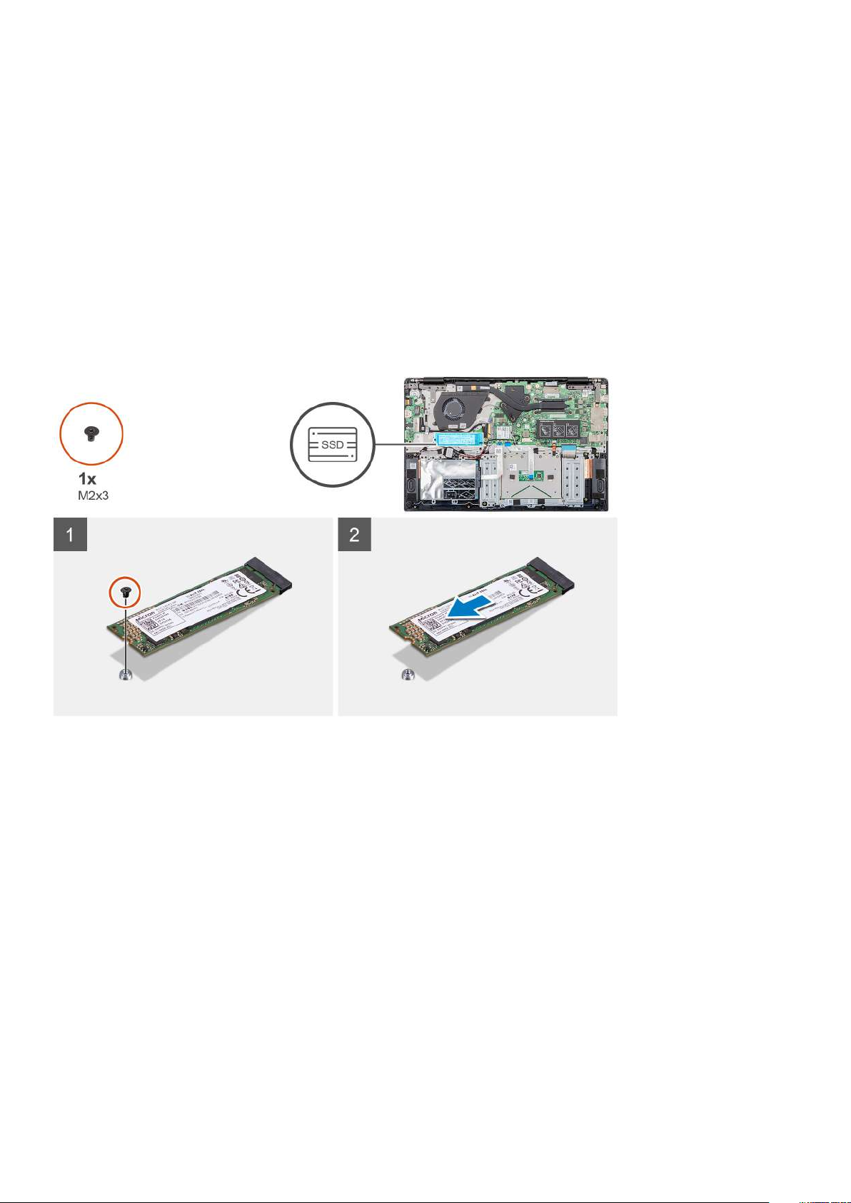
Removing the M.2 2280 solid-state drive...................................................................................................................21
Replacing the SSD support bracket.............................................................................................................................21
Installing M.2 2230 solid-state drive........................................................................................................................... 22
Installing M.2 2242 solid-state drive............................................................................................................................23
Installing M.2 2280 solid-state drive........................................................................................................................... 24
WLAN card...........................................................................................................................................................................25
Removing the WLAN card............................................................................................................................................25
Installing the WLAN card.............................................................................................................................................. 26
Coin-cell battery.................................................................................................................................................................. 27
Removing the coin-cell battery....................................................................................................................................27
Installing the coin-cell battery...................................................................................................................................... 28
Speakers............................................................................................................................................................................... 29
Removing the speakers................................................................................................................................................ 29
Installing the speakers...................................................................................................................................................30
Input and output board....................................................................................................................................................... 32
Removing the input and output board........................................................................................................................32
Installing the input and output board.......................................................................................................................... 33
Heatsink—discrete............................................................................................................................................................. 34
Removing the heatsink assembly-discrete.................................................................................................................34
Contents 3
Page 4

Installing the heatsink assembly-discrete................................................................................................................... 35
Heatsink—UMA.................................................................................................................................................................. 36
Removing the heatsink assembly-UMA......................................................................................................................36
Installing the heatsink assembly-UMA........................................................................................................................ 37
System fan........................................................................................................................................................................... 38
Removing the system fan.............................................................................................................................................38
Installing the system fan............................................................................................................................................... 39
Touchpad...............................................................................................................................................................................41
Removing the touchpad................................................................................................................................................ 41
Installing the touchpad..................................................................................................................................................42
Power-adapter port............................................................................................................................................................ 43
Removing the power-adapter port..............................................................................................................................43
Installing the power-adapter port................................................................................................................................44
System board.......................................................................................................................................................................45
Removing the system board........................................................................................................................................ 45
Installing the system board...........................................................................................................................................47
Power button.......................................................................................................................................................................50
Removing the power button........................................................................................................................................50
Installing the power button........................................................................................................................................... 51
Power button with fingerprint reader...............................................................................................................................52
Removing the power button with fingerprint reader................................................................................................52
Installing the power button with fingerprint reader.................................................................................................. 53
Display assembly..................................................................................................................................................................55
Removing the display assembly...................................................................................................................................55
Installing the display assembly..................................................................................................................................... 58
Palmrest assembly............................................................................................................................................................... 61
Replacing the palmrest assembly................................................................................................................................. 61
3 System setup.............................................................................................................................64
Boot menu............................................................................................................................................................................64
Navigation keys....................................................................................................................................................................64
Boot Sequence.................................................................................................................................................................... 65
System setup options......................................................................................................................................................... 65
Overview........................................................................................................................................................................ 65
Boot options...................................................................................................................................................................66
System information....................................................................................................................................................... 66
Video............................................................................................................................................................................... 68
Security...........................................................................................................................................................................68
Passwords...................................................................................................................................................................... 69
Secure boot.................................................................................................................................................................... 70
Performance...................................................................................................................................................................70
Power management....................................................................................................................................................... 71
Wireless........................................................................................................................................................................... 72
POST behavior............................................................................................................................................................... 72
Virtualization support.................................................................................................................................................... 72
Maintenance...................................................................................................................................................................73
System logs.................................................................................................................................................................... 73
Updating the BIOS in Windows ........................................................................................................................................ 73
Updating BIOS on systems with BitLocker enabled..................................................................................................74
Updating your system BIOS using a USB flash drive................................................................................................ 74
4
Contents
Page 5

System and setup password..............................................................................................................................................75
Assigning a system setup password............................................................................................................................75
Deleting or changing an existing system setup password........................................................................................76
4 Troubleshooting......................................................................................................................... 77
Enhanced Pre-Boot System Assessment (ePSA) diagnostics...................................................................................... 77
Running the ePSA diagnostics..................................................................................................................................... 77
Diagnostics............................................................................................................................................................................77
M-BIST............................................................................................................................................................................78
L-BIST............................................................................................................................................................................. 78
System diagnostic lights..................................................................................................................................................... 78
WiFi power cycle..................................................................................................................................................................79
5 Getting help...............................................................................................................................80
Contacting Dell.................................................................................................................................................................... 80
Contents 5
Page 6

1
Working on your computer
Safety instructions
Prerequisites
Use the following safety guidelines to protect your computer from potential damage and to ensure your personal safety. Unless otherwise
noted, each procedure included in this document assumes that the following conditions exist:
• You have read the safety information that shipped with your computer.
• A component can be replaced or, if purchased separately, installed by performing the removal procedure in reverse order.
About this task
NOTE: Disconnect all power sources before opening the computer cover or panels. After you finish working inside the
computer, replace all covers, panels, and screws before connecting to the power source.
WARNING: Before working inside your computer, read the safety information that shipped with your computer. For
additional safety best practices information, see the Regulatory Compliance Homepage
CAUTION: Many repairs may only be done by a certified service technician. You should only perform troubleshooting and
simple repairs as authorized in your product documentation, or as directed by the online or telephone service and
support team. Damage due to servicing that is not authorized by Dell is not covered by your warranty. Read and follow
the safety instructions that came with the product.
CAUTION: To avoid electrostatic discharge, ground yourself by using a wrist grounding strap or by periodically touching
an unpainted metal surface at the same time as touching a connector on the back of the computer.
CAUTION: Handle components and cards with care. Do not touch the components or contacts on a card. Hold a card by
its edges or by its metal mounting bracket. Hold a component such as a processor by its edges, not by its pins.
CAUTION: When you disconnect a cable, pull on its connector or on its pull-tab, not on the cable itself. Some cables
have connectors with locking tabs; if you are disconnecting this type of cable, press in on the locking tabs before you
disconnect the cable. As you pull connectors apart, keep them evenly aligned to avoid bending any connector pins. Also,
before you connect a cable, ensure that both connectors are correctly oriented and aligned.
NOTE: The color of your computer and certain components may appear differently than shown in this document.
Turning off your computer — Windows 10
About this task
CAUTION:
computer or remove the side cover.
Steps
1. Click or tap .
To avoid losing data, save and close all open files and exit all open programs before you turn off your
2. Click or tap and then click or tap Shut down.
6 Working on your computer
Page 7

NOTE: Ensure that the computer and all attached devices are turned off. If your computer and attached devices did
not automatically turn off when you shut down your operating system, press and hold the power button for about 6
seconds to turn them off.
Before working inside your computer
About this task
To avoid damaging your computer, perform the following steps before you begin working inside the computer.
Steps
1. Ensure that you follow the Safety Instruction.
2. Ensure that your work surface is flat and clean to prevent the computer cover from being scratched.
3. Turn off your computer.
4. Disconnect all network cables from the computer.
CAUTION: To disconnect a network cable, first unplug the cable from your computer and then unplug the cable from
the network device.
5. Disconnect your computer and all attached devices from their electrical outlets.
6. Press and hold the power button while the computer is unplugged to ground the system board.
NOTE: To avoid electrostatic discharge, ground yourself by using a wrist grounding strap or by periodically touching
an unpainted metal surface at the same time as touching a connector on the back of the computer.
After working inside your computer
About this task
After you complete any replacement procedure, ensure that you connect any external devices, cards, and cables before turning on your
computer.
Steps
1. Connect any telephone or network cables to your computer.
CAUTION:
computer.
2. Connect your computer and all attached devices to their electrical outlets.
3. Turn on your computer.
4. If required, verify that the computer works correctly by running ePSA diagnostics.
To connect a network cable, first plug the cable into the network device and then plug it into the
Working on your computer
7
Page 8
Removing and installing components
Recommended tools
The procedures in this document require the following tools:
• Phillips #0 screwdriver
• Phillips #1 screwdriver
• Plastic scribe
NOTE: The #0 screw driver is for screws 0-1 and the #1 screw driver is for screws 2-4
Screw List
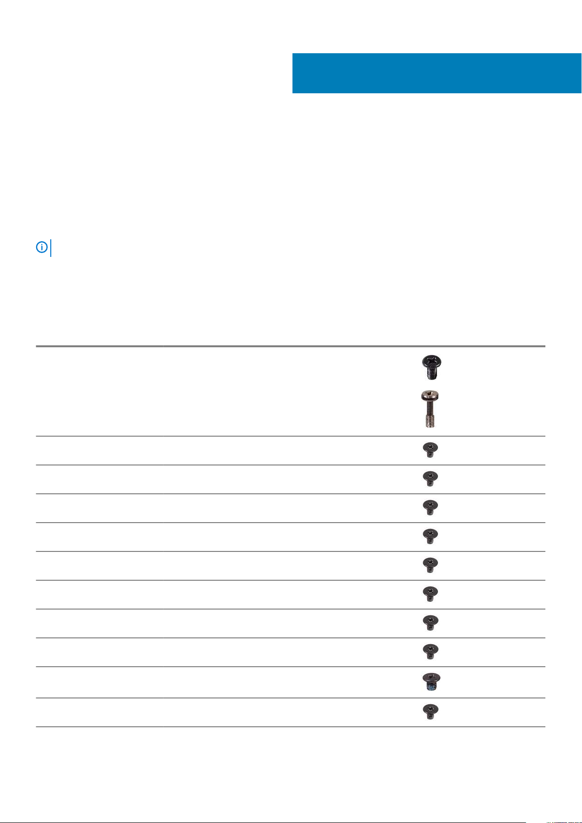
The following table shows the screw list and the images for different components.
Table 1. Screw Size List
Component Screw type Quantity Image
2
Base cover M2.5x5
M2X8 (captive screws)
Battery M2x3 4
WLAN M2x3 1
System fan M2x3 2
DC-In M2x3 1
SSD M2x3 1
Input output board M2x3 2
USB Type-C bracket M2x3 2
7
2
HDD assembly M2x3 4
HDD bracket M3x3 4
Power button M2x3 2
8 Removing and installing components
Page 9
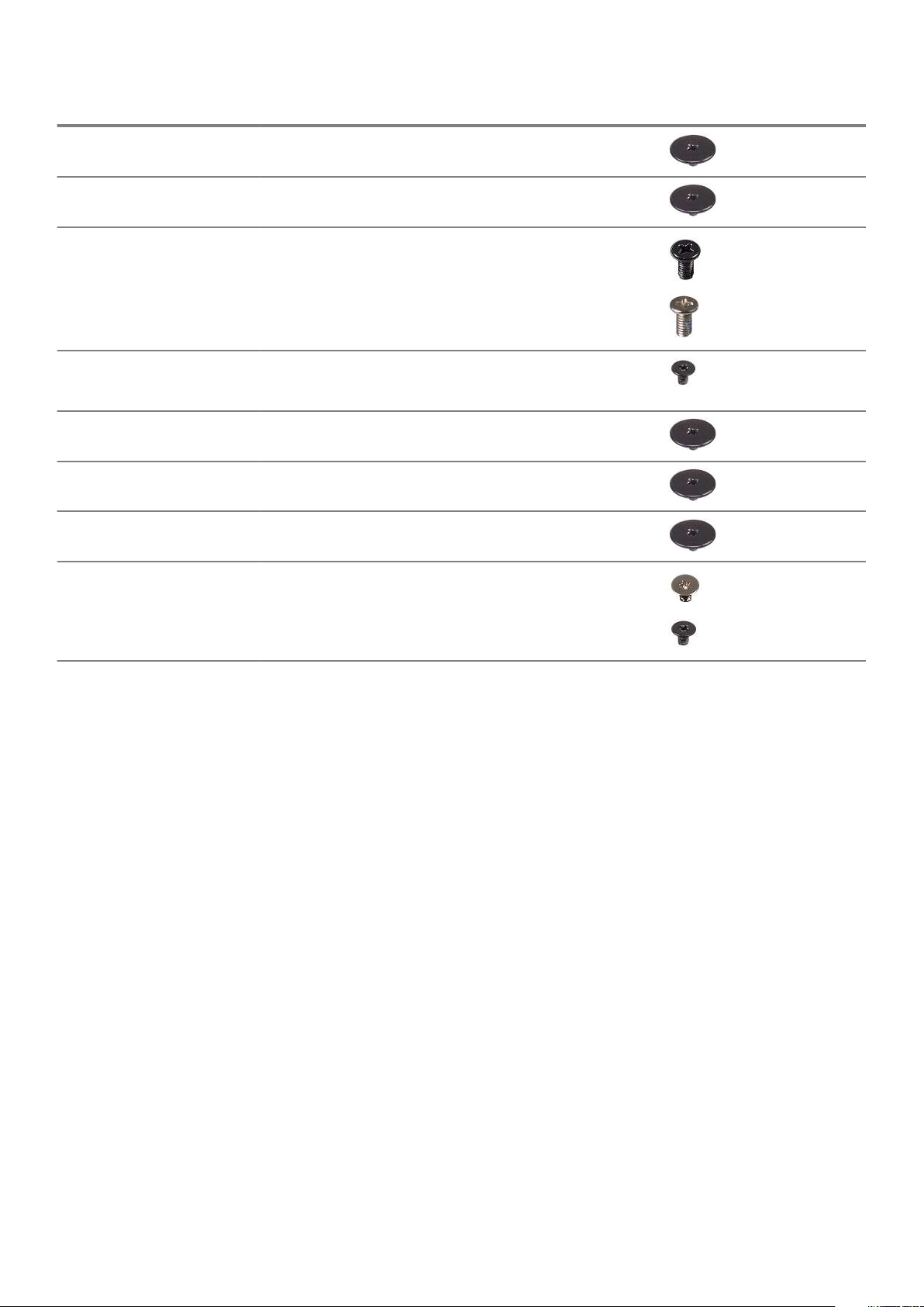
Component Screw type Quantity Image
Touchpad button bracket M2x2 (Big Head) 3
Touchpad board M2x2 (Big Head) 4
Hinge plate M2.5x5
M2x4
Heatsink - UMA
Heatsink - Discrete
System board M2x2 (Big head) 5
Fingerprint board M2x2 (Big Head) 2
Power button board M2x2 (Big Head) 2
Display Hinges M2.5x2.5 (Big head)
M2x3
M2x3
M2x3
4
2
4
7
4
2
Base cover
Removing the base cover
Prerequisites
1. Follow the procedure in Before working inside your computer.
About this task
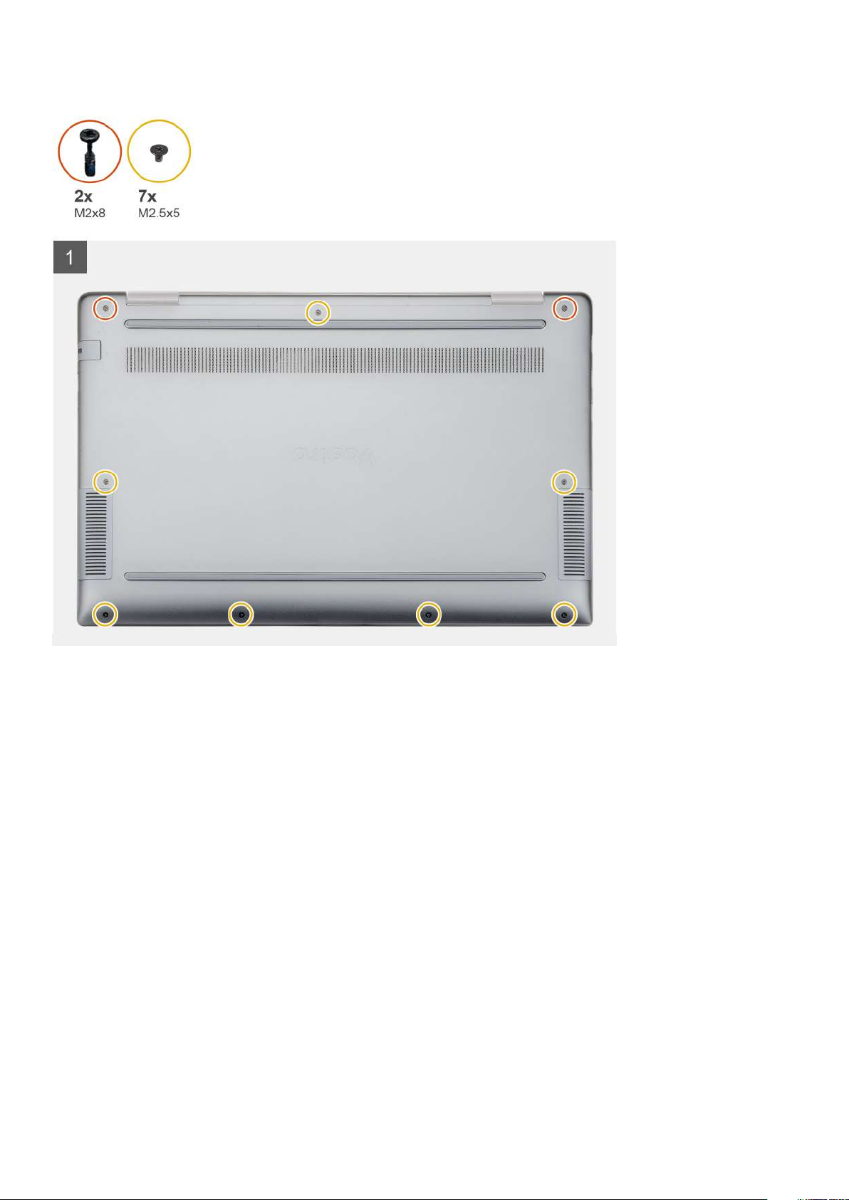
The figure indicates the location of the base cover and provides a visual representation of the removal procedure.
Removing and installing components
9
Page 10
10 Removing and installing components
Page 11
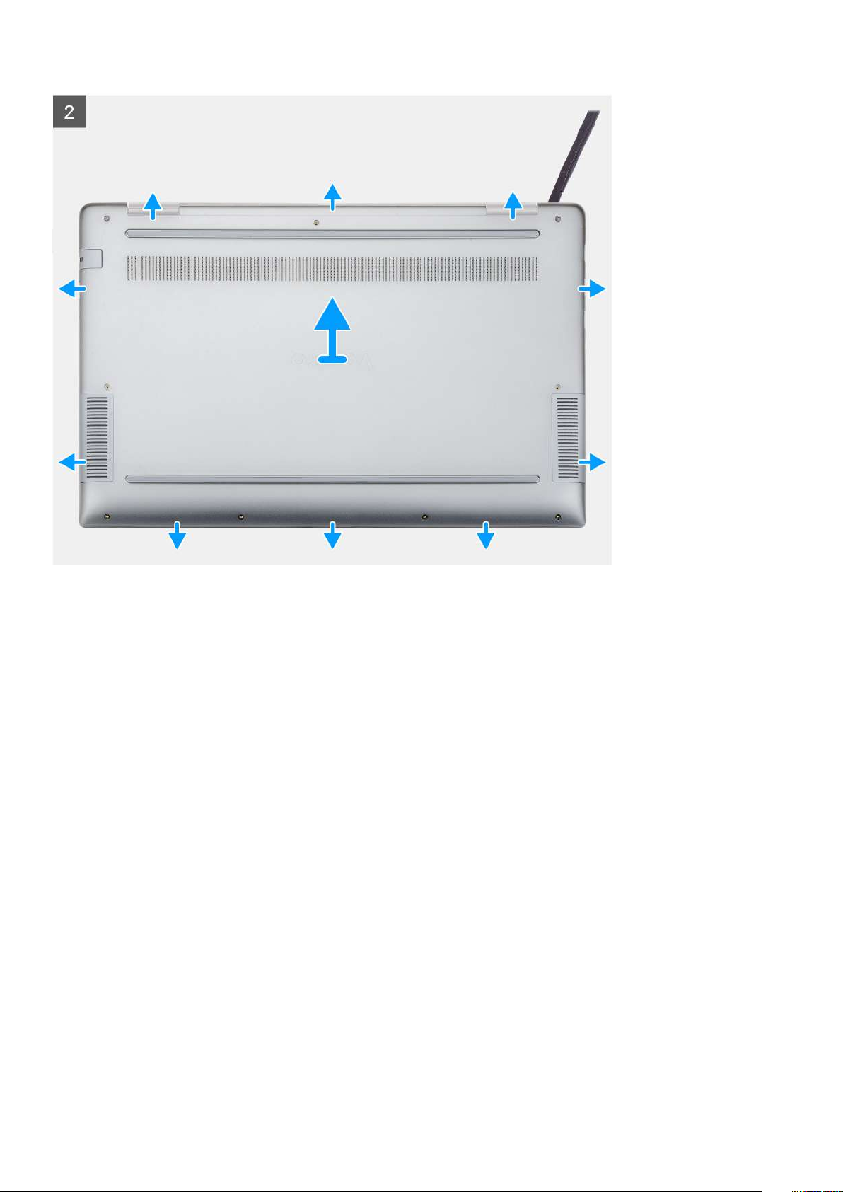
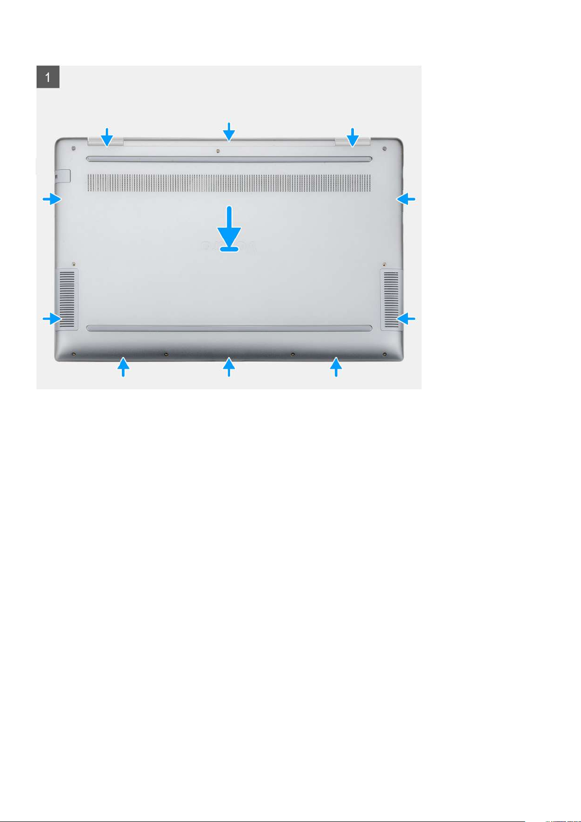
Steps
1. Remove the seven (M2.5x5) screws and loosen the two (M2x8) captive screws that secure the base cover to the computer.
2. Pry the base cover starting from the right hinge and work your way around.
3. Lift the base cover away from the computer.
Installing the base cover
Prerequisites
If you are replacing a component, remove the existing component before performing the installation procedure.
About this task
The figure indicates the location of the base cover and provides a visual representation of the installation procedure.
Removing and installing components
11
Page 12
12 Removing and installing components
Page 13
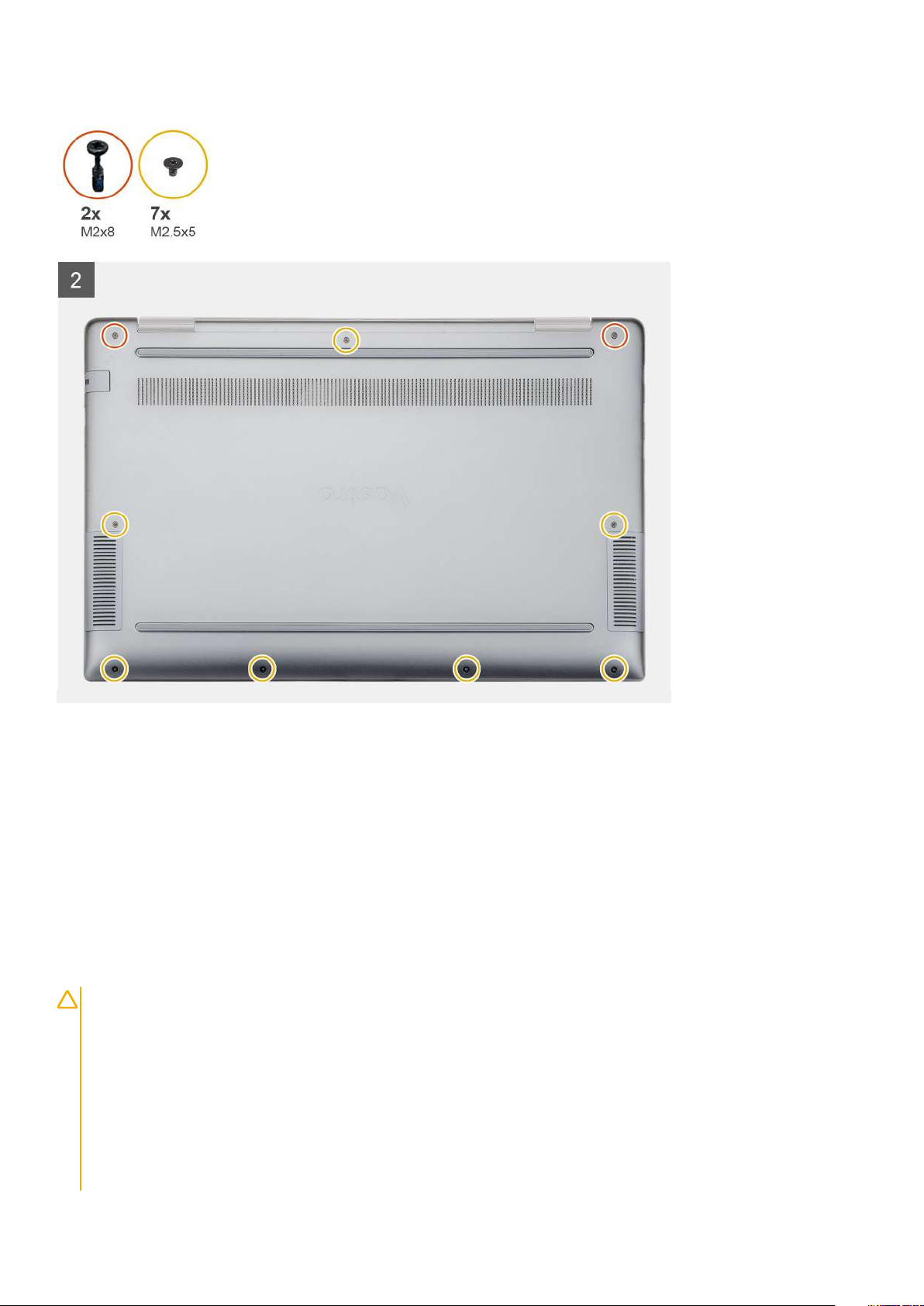
Steps
1. Place the base cover on the palmrest and keyboard assembly, and snap the base cover into place.
2. Replace the seven (M2.5x5) and tighten the two (M2x8) captive screws to secure the base cover to the computer.
Next steps
1. Follow the procedure in After working inside your computer.
Battery
Lithium-ion battery precautions
CAUTION:
• Exercise caution when handling Lithium-ion batteries.
• Discharge the battery as much as possible before removing it from the system. This can be done by disconnecting
the AC adapter from the system to allow the battery to drain.
• Do not crush, drop, mutilate, or penetrate the battery with foreign objects.
• Do not expose the battery to high temperatures, or disassemble battery packs and cells.
• Do not apply pressure to the surface of the battery.
• Do not bend the battery.
• Do not use tools of any kind to pry on or against the battery.
Removing and installing components 13
Page 14
• Ensure any screws during the servicing of this product are not lost or misplaced, to prevent accidental puncture or
damage to the battery and other system components.
• If a battery gets stuck in a device as a result of swelling, do not try to free it as puncturing, bending, or crushing a
Lithium-ion battery can be dangerous. In such an instance, contact for assistance and further instructions.
• If the battery gets stuck inside your computer as a result of swelling, do not try to release it as puncturing, bending,
or crushing a lithium-ion battery can be dangerous. In such an instance, contact Dell technical support for
assistance. See www.dell.com/contactdell.
• Always purchase genuine batteries from www.dell.com or authorized Dell partners and resellers.
Removing the battery
Prerequisites
1. Follow the procedure in Before working inside your computer.
2. Remove the base cover.
About this task
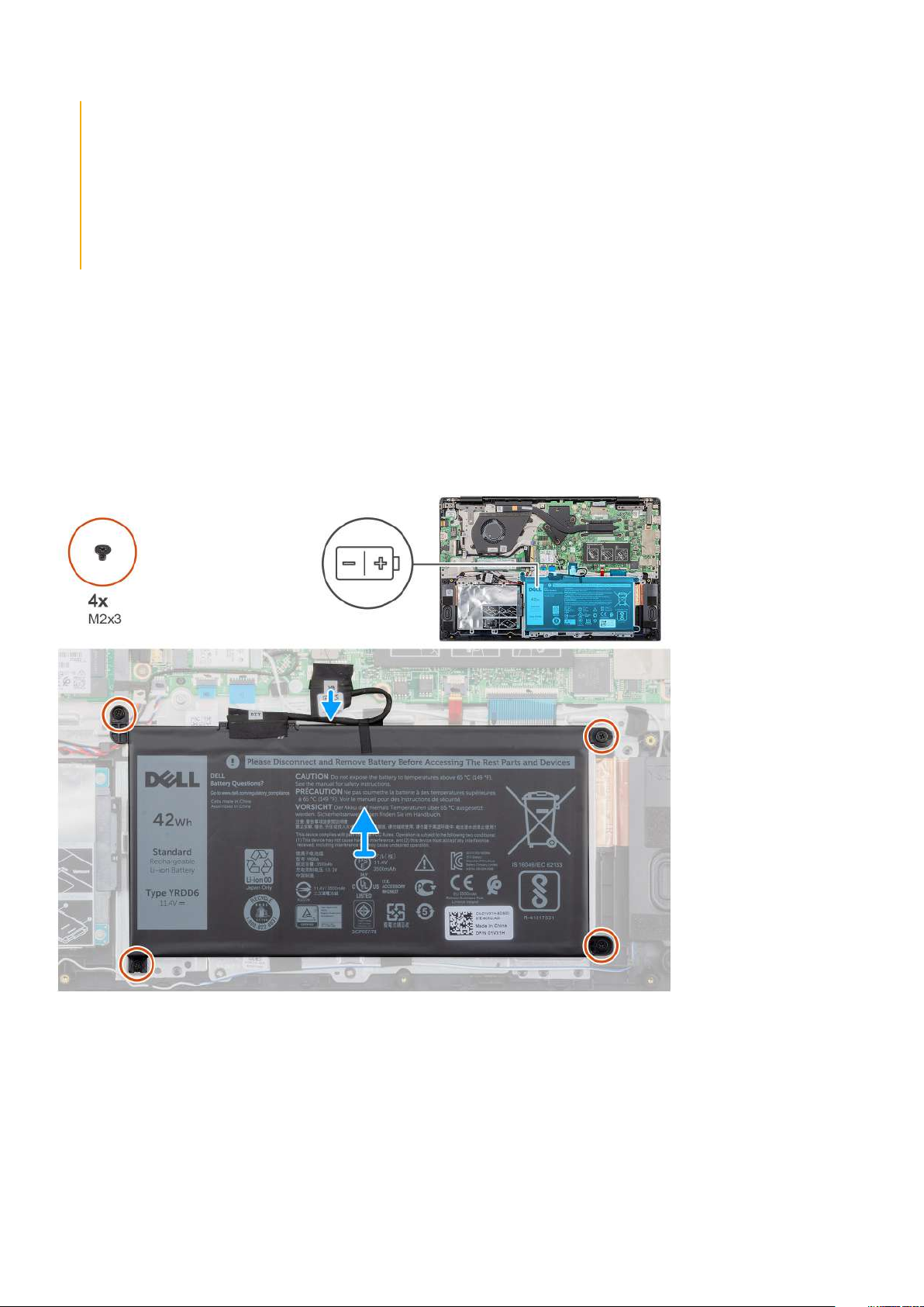
The figure indicates the location of the battery and provides a visual representation of the removal procedure.
Steps
1. Disconnect the battery cable from the system board.
2. Remove the four (M2x3) screws that secure the battery to the palmrest.
3. Lift the battery away from the computer.
Removing and installing components
14
Page 15
Installing the battery
Prerequisites
If you are replacing a component, remove the existing component before performing the installation procedure.
About this task
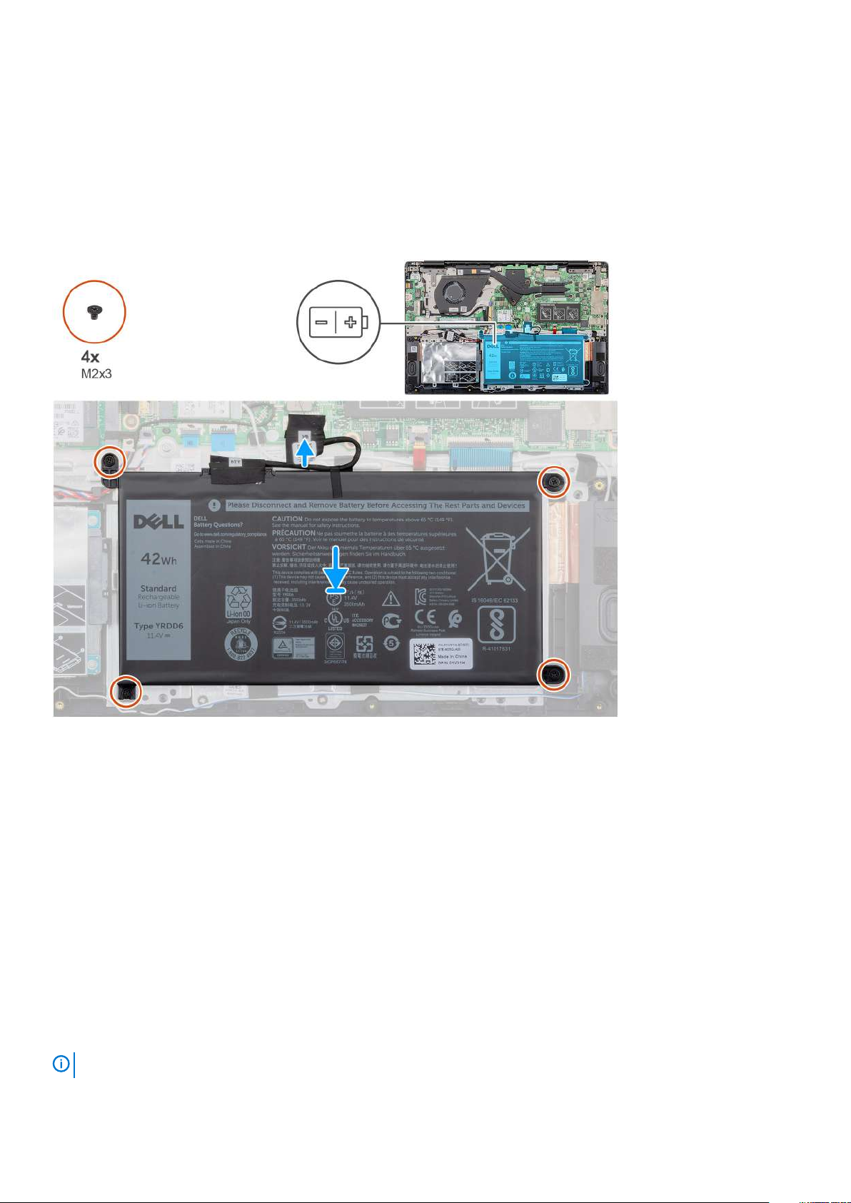
The figure indicates the location of the battery and provides a visual representation of the installation procedure.
Steps
1. Place the battery on the palmrest and align the screw holes on the battery with the screw holes on the palmrest.
2. Replace the four (M2x3) screws to secure the battery to the palmrest.
3. Connect the battery cable to the connector on the system board.
Next steps
1. Install the base cover.
2. Follow the procedure in After working inside your computer.
Memory modules
Removing the secondary memory module
Prerequisites
NOTE: Primary memory module is integrated into the system board.
Removing and installing components 15
Page 16
1. Follow the procedure in Before working inside your computer.
2. Remove the base cover.
3. Remove the battery.
About this task
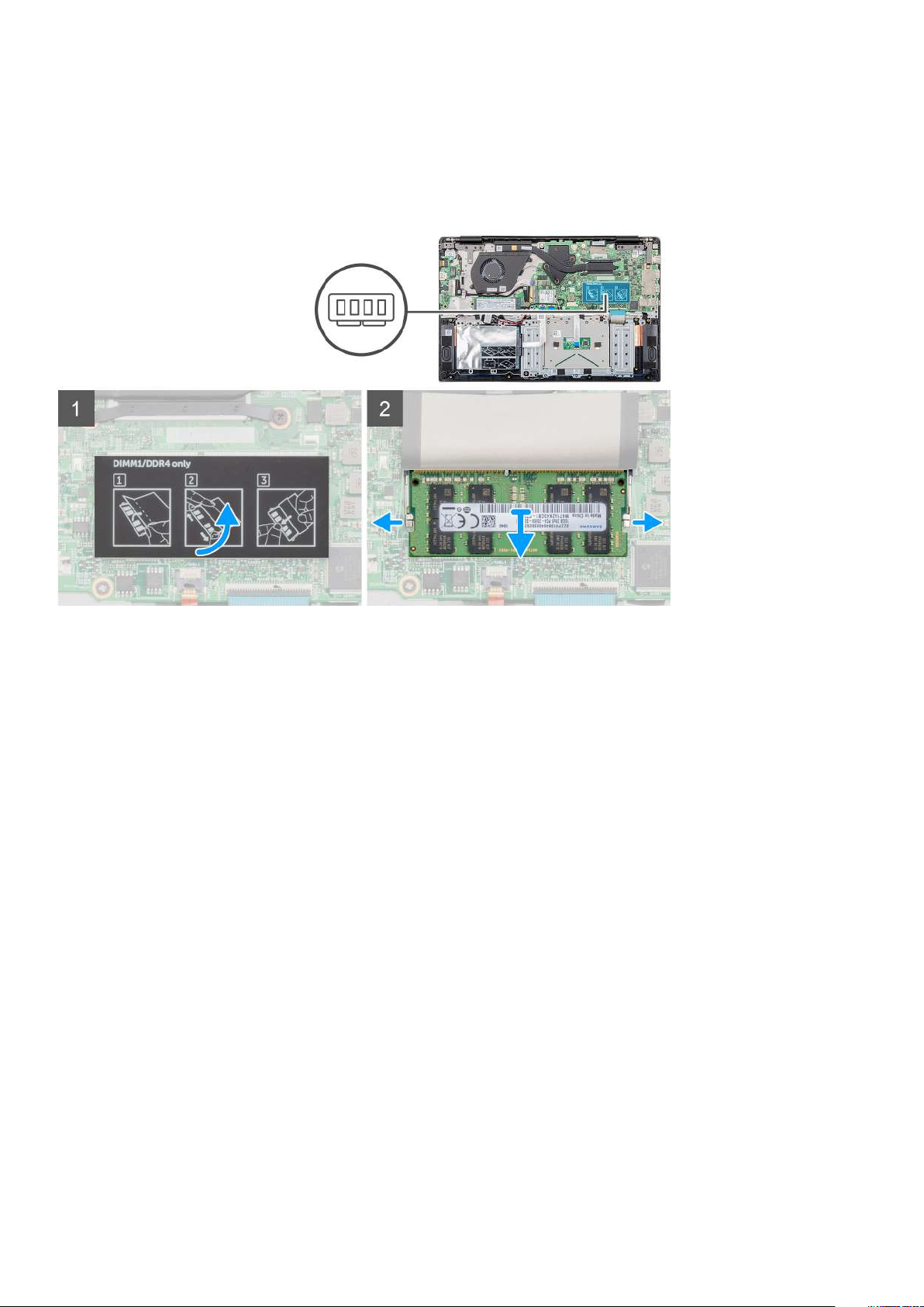
The figure indicates the location of the memory module and provides a visual representation of the removal procedure.
Steps
1. Peel the adhesive tape, above the memory module, to a 90-degree angle.
2. Using your finger tips gently pry the retention clips away from the memory module until the memory module pops up.
3. Slide and remove the memory module from the memory module slot on the system board.
Installing the secondary memory module
Prerequisites
If you are replacing a component, remove the existing component before performing the installation procedure.
About this task
The figure indicates the location of the memory module and provides a visual representation of the installation procedure.
16
Removing and installing components
Page 17
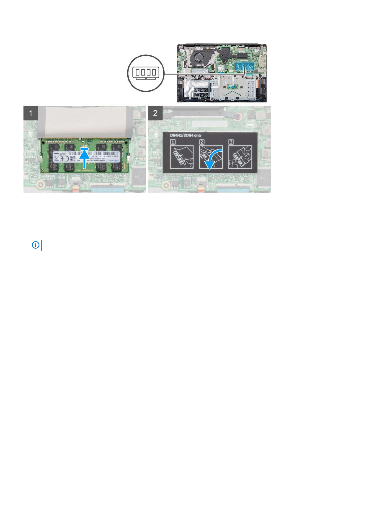
Steps
1. Align the notch on the memory module with the tab on the memory module slot.
2. Slide the memory module firmly into the slot at an angle.
3. Press the memory module down until it clicks into place.
NOTE: If you do not hear the click, remove the memory module and reinstall it.
4. Affix the adhesive tape above the memory module.
Next steps
1. Install the battery.
2. Install the base cover.
3. Follow the procedure in After working inside your computer.
Hard drive
Removing the hard drive
Prerequisites
1. Follow the procedure in Before working inside your computer.
2. Remove the base cover.
3. Remove the battery.
About this task
The figure indicates the location of the 2.5 in. hard-drive module and provides a visual representation of the removal procedure.
Removing and installing components
17
Page 18
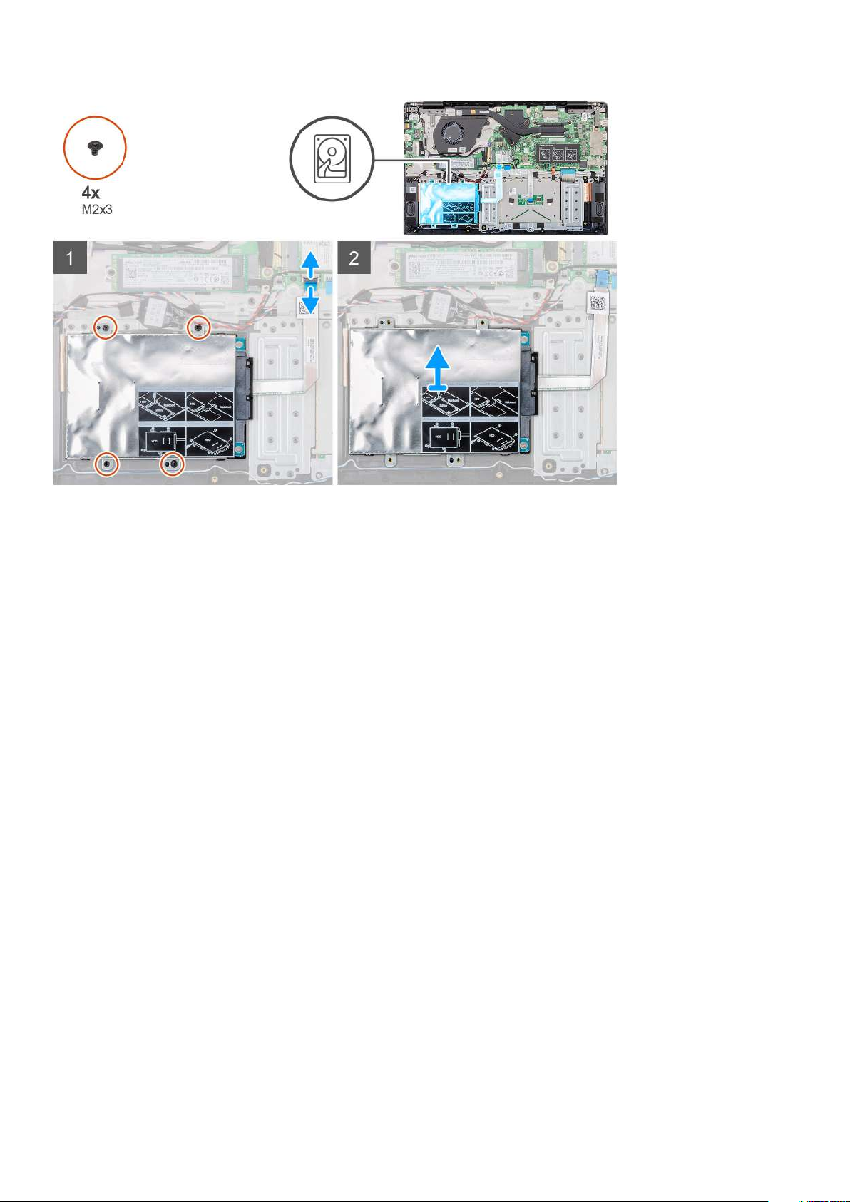
Steps
1. Release the latch and disconnect the hard-drive cable from the connector on the system board.
2. Remove the four (M2x3) screws that secure the hard-drive module to the palmrest assembly.
3. Slide the hard-drive module out from the computer.
Installing the hard drive
Prerequisites
If you are replacing a component, remove the existing component before performing the installation procedure.
About this task
The figure indicates the location of the 2.5 in. hard-drive module and provides a visual representation of the installation procedure.
18
Removing and installing components
Page 19
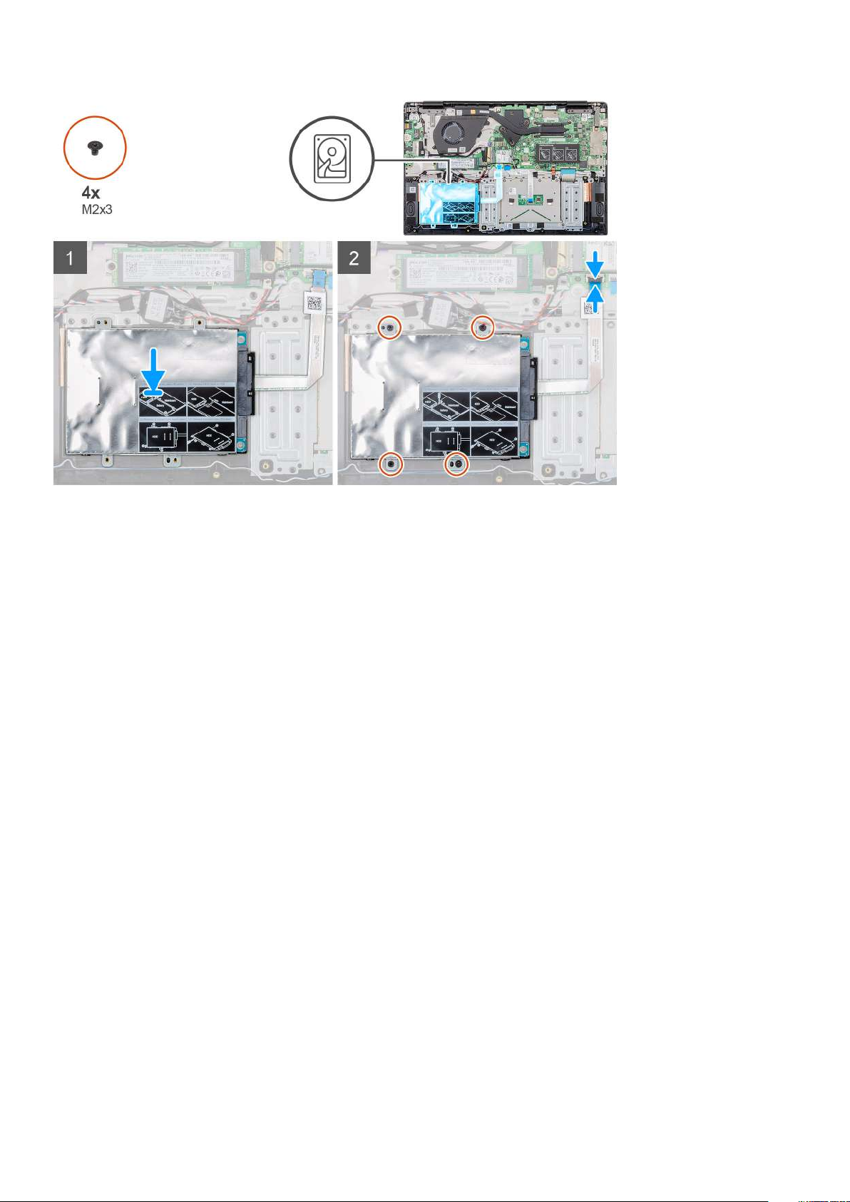
Steps
1. Place the hard-drive module on the system and align the screw holes on the hard drive module with the screw holes on the palmrest
assembly.
2. Replace the four (M2x3) screws to secure the hard-drive module to the palmrest assembly.
3. Connect the hard-drive cable to the connector on the system board and close the latch to secure the cable.
Next steps
1. Install the battery.
2. Install the base cover.
3. Follow the procedure in After working inside your computer.
Solid state drive
Removing the M.2 2230 solid-state drive
Prerequisites
1. Follow the procedure in Before working inside your computer.
2. Remove the base cover.
3. Remove the battery.
About this task
The figure indicates the location of the M.2 2230 solid-state drive and provides a visual representation of the removal procedure.
Removing and installing components
19
Page 20
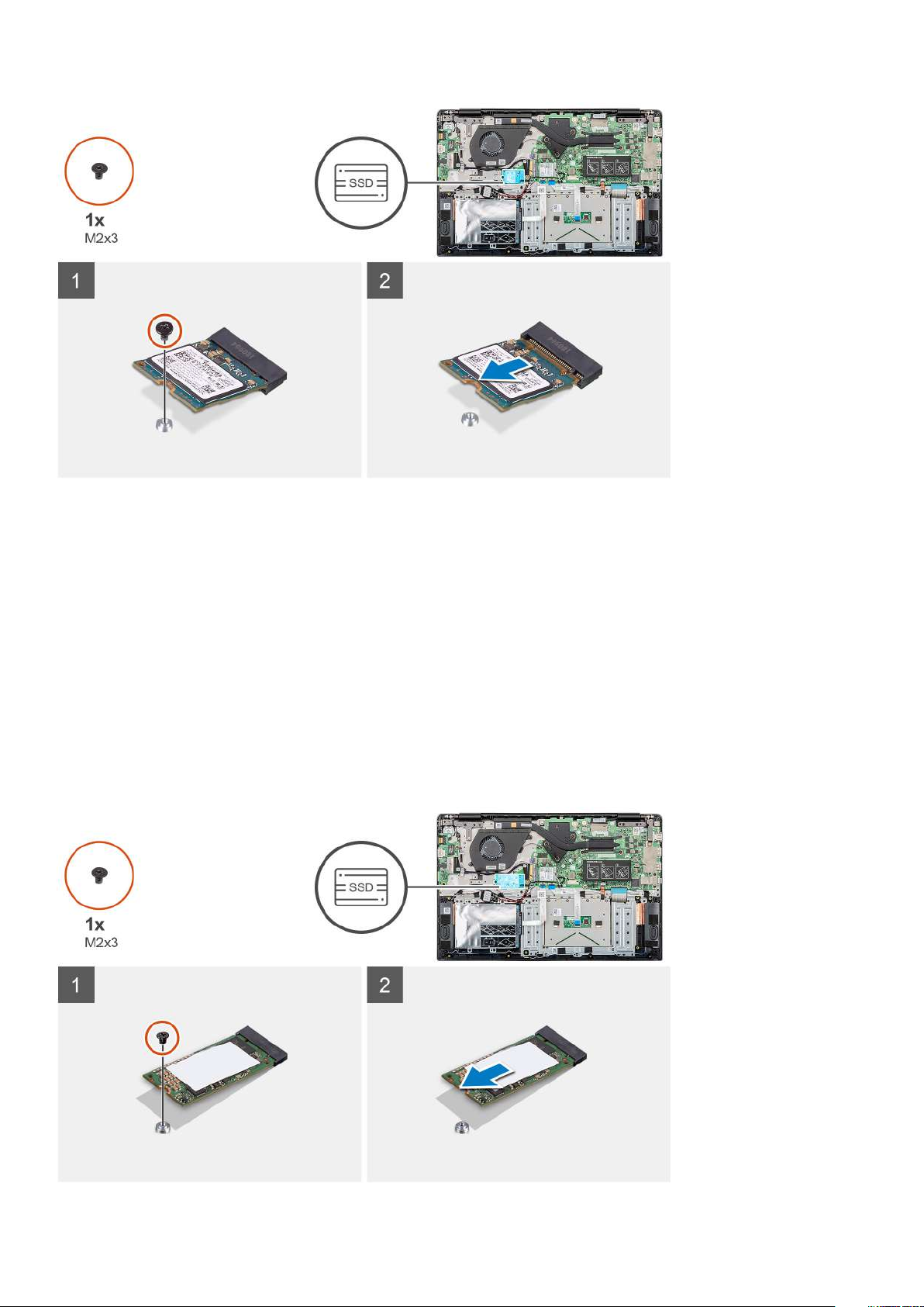
Steps
1. Remove the single (M2x3) screw that secures the solid-state module to the palmrest assembly.
2. Slide the solid-state module out from the M.2 slot.
Removing the M.2 2242 solid-state drive
Prerequisites
1. Follow the procedure in Before working inside your computer.
2. Remove the base cover.
3. Remove the battery.
About this task
The figure indicates the location of the M.2 2242 solid-state drive and provides a visual representation of the removal procedure.
20
Removing and installing components
Page 21
Steps
1. Remove the single (M2x3) screw that secures the solid-state module to the palmrest assembly.
2. Slide the solid-state module out from the M.2 slot.
Removing the M.2 2280 solid-state drive
Prerequisites
1. Follow the procedure in Before working inside your computer.
2. Remove the base cover.
3. Remove the battery.
About this task
The figure indicates the location of the M.2 2280 solid-state drive and provides a visual representation of the removal procedure.
Steps
1. Remove the single (M2x3) screw that secures the solid-state module to the palmrest assembly.
2. Slide the solid-state module out from the M.2 slot.
Replacing the SSD support bracket
Prerequisites
1. Follow the procedure in Before working inside your computer.
2. Remove the base cover.
3. Remove the battery.
4. Remove the M.2 2230 SSD or M.2 2242 SSD or M.2 2280 SSD.
About this task
The figure indicates the location of the SSD support bracket and provides a visual representation of the replace procedure.
Removing and installing components
21
Page 22
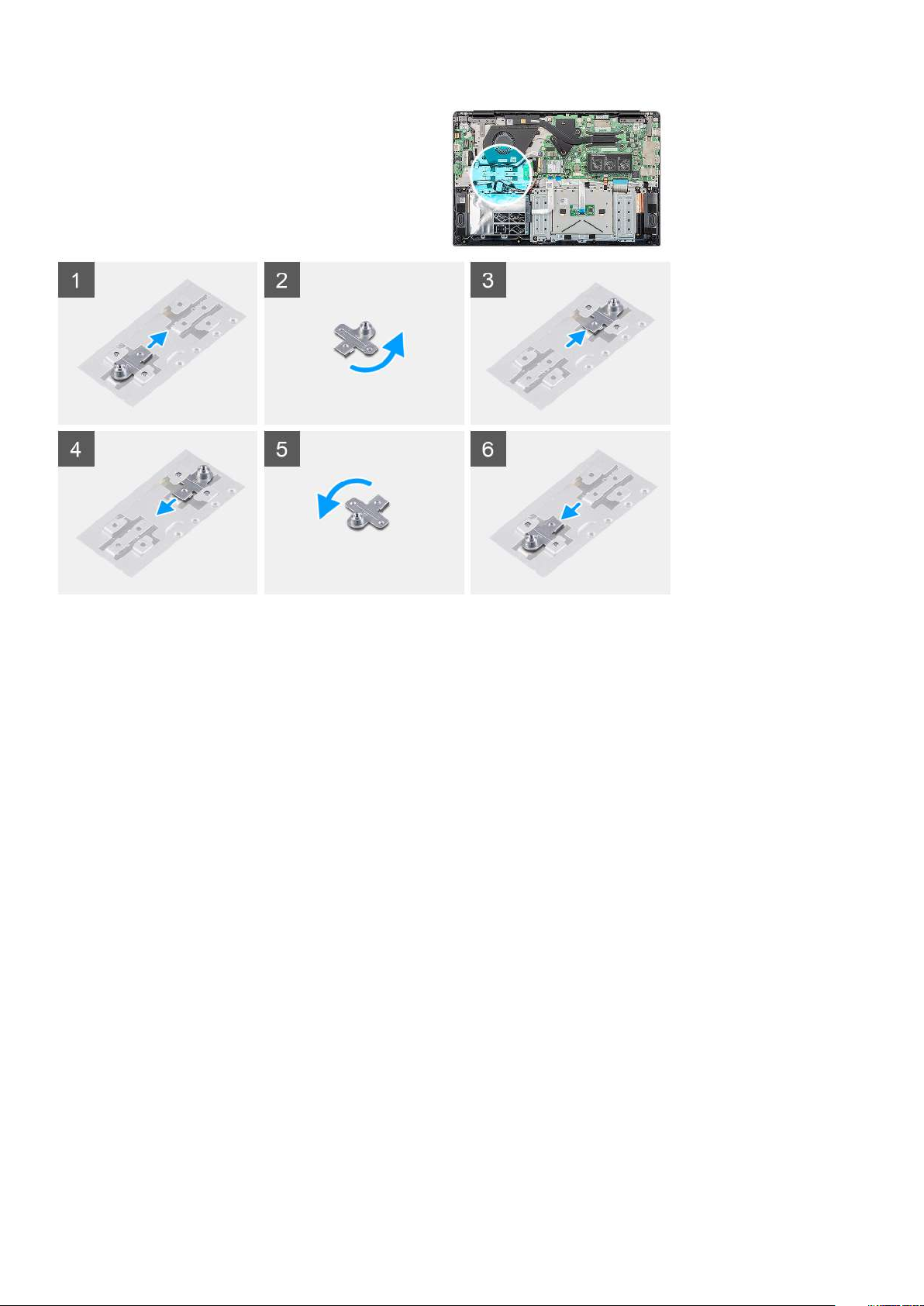
Steps
1. Slide and remove the SSD support bracket from the support bracket slot.
2. Depending on the type of solid-state drive (M.2 2230/ M.2 2242/ M.2 2280), align and insert the SSD support bracket into the
support bracket slot.
3. Install the solid-state drive.
Installing M.2 2230 solid-state drive
Prerequisites
If you are replacing a component, remove the existing component before performing the installation procedure.
About this task
The figure indicates the location of the M.2 2230 solid-state drive and provides a visual representation of the installation procedure.
Removing and installing components
22
Page 23
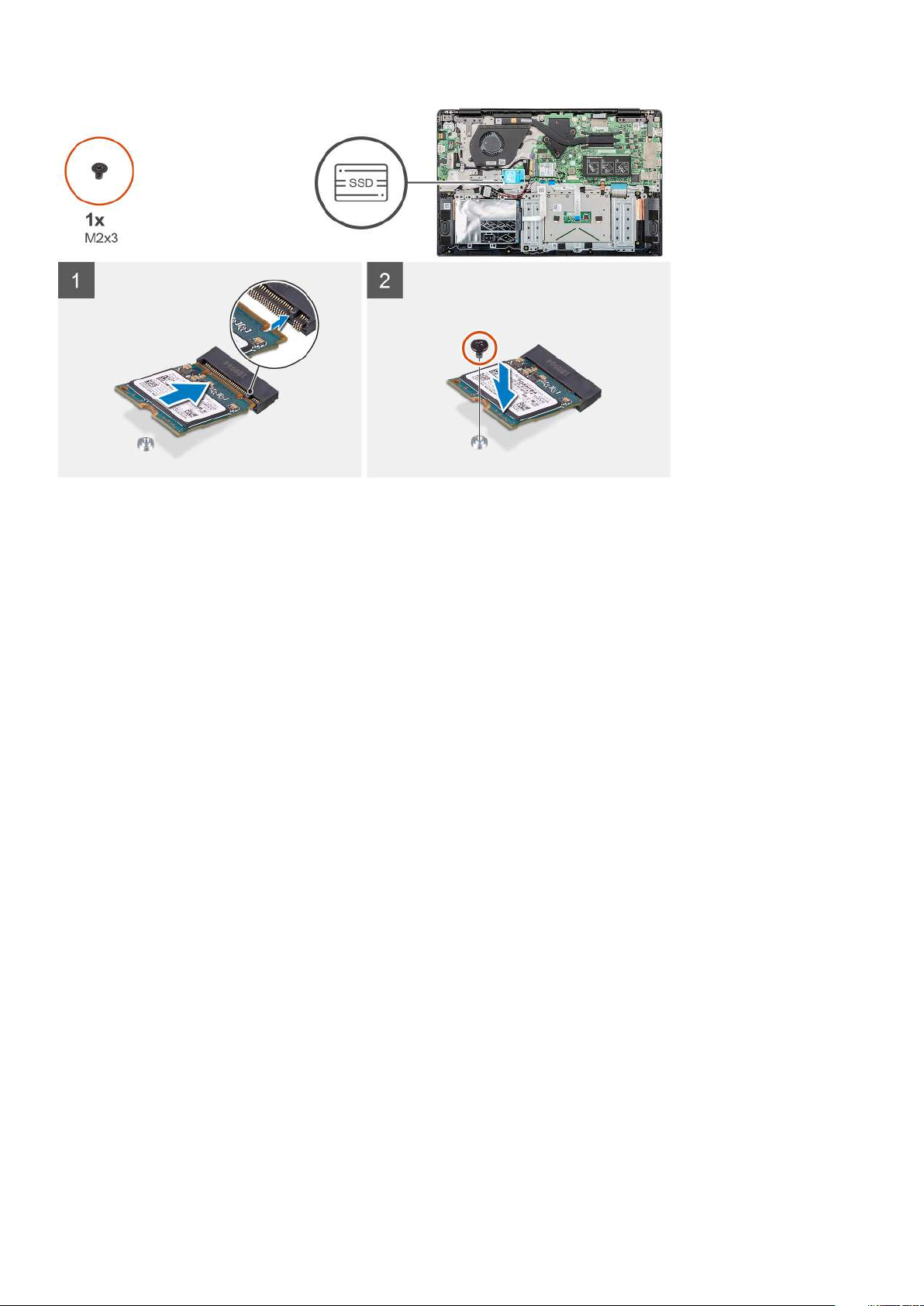
Steps
1. Align and slide the solid-state drive into the slot.
2. Replace the single (M2x3) screw to secure the solid-state drive module to the palmrest and keyboard assembly.
Next steps
1. Install the battery.
2. Install the base cover.
3. Follow the procedure in After working inside your computer.
Installing M.2 2242 solid-state drive
Prerequisites
If you are replacing a component, remove the existing component before performing the installation procedure.
About this task
The figure indicates the location of the M.2 2242 solid-state drive and provides a visual representation of the installation procedure.
Removing and installing components
23
Page 24

Steps
1. Align and slide the solid-state drive into the M.2 slot.
2. Replace the single (M2x3) screw to secure the solid-state drive module to the palmrest assembly.
Next steps
1. Install the battery.
2. Install the base cover.
3. Follow the procedure in After working inside your computer.
Installing M.2 2280 solid-state drive
Prerequisites
If you are replacing a component, remove the existing component before performing the installation procedure.
About this task
The figure indicates the location of the M.2 2280 solid-state drive and provides a visual representation of the installation procedure.
24
Removing and installing components
Page 25

Steps
1. Align and slide the solid-state drive into the M.2 slot.
2. Replace the single (M2x3) screw to secure the solid-state drive module to the palmrest assembly.
Next steps
1. Install the battery.
2. Install the base cover.
3. Follow the procedure in After working inside your computer.
WLAN card
Removing the WLAN card
Prerequisites
1. Follow the procedure in Before working inside your computer.
2. Remove the base cover.
3. Remove the battery.
About this task
The figure indicates the location of the WLAN card and provides a visual representation of the removal procedure.
Removing and installing components
25
Page 26

Steps
1. Remove the single (M2x3) screw that secures the WLAN bracket to the computer.
2. Remove the WLAN bracket.
3. Disconnect the WLAN antenna cables from the WLAN module.
4. Slide and remove the WLAN card from the WLAN card slot.
Installing the WLAN card
Prerequisites
If you are replacing a component, remove the existing component before performing the installation procedure.
About this task
The figure indicates the location of the WLAN card and provides a visual representation of the installation procedure.
Removing and installing components
26
Page 27

Steps
1. Align the notch on the WLAN card with the tab on the WLAN-card slot and insert the WLAN card at an angle into the WLAN-card
slot.
2. Connect the WLAN antenna cables to the WLAN card.
3. Align and place the WLAN-card bracket to secure the WLAN card to the system board.
4. Replace the single (M2x3) screw to secure the WLAN card to the system board.
Next steps
1. Install the battery.
2. Install the base cover.
3. Follow the procedure in After working inside your computer.
Coin-cell battery
Removing the coin-cell battery
Prerequisites
1. Follow the procedure in Before working inside your computer.
2. Remove the base cover.
3. Remove the battery.
Removing and installing components
27
Page 28

About this task
The figure indicates the location of the coin-cell and provides a visual representation of the removal procedure.
Steps
1. Disconnect the coin-cell battery cable from the system board.
2. Remove the coin-cell battery cable from the routing guide.
3. Peel the coin-cell battery off the palmrest assembly.
Installing the coin-cell battery
Prerequisites
If you are replacing a component, remove the existing component before performing the installation procedure.
About this task
The figure indicates the location of the coin-cell and provides a visual representation of the installation procedure.
28
Removing and installing components
Page 29

Steps
1. Adhere the coin-cell battery to the slot on the palmrest assembly.
2. Route the coin-cell battery cable through the routing guide.
3. Connect the coin-cell battery cable to the system board.
Next steps
1. Install the battery.
2. Install the base cover.
3. Follow the procedure in After working inside your computer.
Speakers
Removing the speakers
Prerequisites
1. Follow the procedure in Before working inside your computer.
2. Remove the base cover.
3. Remove the battery.
About this task
The figure indicates the location of the speakers and provides a visual representation of the removal procedure.
Removing and installing components
29
Page 30

Steps
1. Locate the speakers on your computer.
2. Disconnect the speaker cable from the connector on the system board.
3. Peel the adhesive tape that secures the speaker cable.
4. Unroute the speaker cables from the retention clips on the computer.
5. Lift the speakers out of the computer.
Installing the speakers
Prerequisites
If you are replacing a component, remove the existing component before performing the installation procedure.
About this task
The figure indicates the location of the speakers and provides a visual representation of the installation procedure.
Removing and installing components
30
Page 31

Steps
1. Locate the speaker slot on your computer.
2. Align and place the speakers in the slot on your computer.
3. Connect the speaker cable to the connector on the system board.
4. Route the speaker cables through the retention clips on your computer.
5. Adhere the adhesive tape to secure the speaker cable.
Next steps
1. Install the battery.
2. Install the base cover.
3. Follow the procedure in After working inside your computer.
Removing and installing components
31
Page 32

Input and output board
Removing the input and output board
Prerequisites
1. Follow the procedure in Before working inside your computer.
2. Remove the base cover.
3. Remove the battery.
About this task
The figure indicates the location of the input and output board and provides a visual representation of the removal procedure.
Steps
1. Locate the input and output board on your computer.
2. Lift the latch and disconnect the input and output board cable from the connector on the system board.
3. Unroute the input and output board cables from the retention clips on the computer.
4. Remove the two (M2x3) screws that secure the input and output board to the palmrest assembly.
Removing and installing components
32
Page 33

5. Lift the input and output board out of the computer.
Installing the input and output board
Prerequisites
If you are replacing a component, remove the existing component before performing the installation procedure.
About this task
The figure indicates the location of the input and output board and provides a visual representation of the installation procedure.
Steps
1. Align and place the input and output board in the slot on your computer.
2. Replace the two (M2x3) screws to secure the input and output board to the palmrest assembly.
3. Connect the input and output board cable to the connector on the system board.
4. Route the input and output board cables through the retention clips on your computer.
Next steps
1. Install the battery.
Removing and installing components
33
Page 34

2. Install the base cover.
3. Follow the procedure in After working inside your computer.
Heatsink—discrete
Removing the heatsink assembly-discrete
Prerequisites
1. Follow the procedure in Before working inside your computer.
2. Remove the base cover.
3. Remove the battery.
About this task
The figure indicates the location of the heatsink assembly and provides a visual representation of the removal procedure.
Steps
1. Locate the heatsink assembly on your computer.
Removing and installing components
34
Page 35

2. Remove the seven (M2x3) screws that secure the heatsink assembly to the system board.
NOTE: Remove the screws in the order of the callout numbers [1, 2, 3, 4, 5, 6, 7] as indicated on the heatsink.
3. Lift the heatsink assembly out of the computer.
Installing the heatsink assembly-discrete
Prerequisites
If you are replacing a component, remove the existing component before performing the installation procedure.
About this task
The figure indicates the location of the heatsink and provides a visual representation of the installation procedure.
Steps
1. Locate the heatsink assembly slot on your computer.
2. Align and place the heatsink assembly into the slot.
3. Replace the seven (M2x3) screws to secure the heatsink assembly to the system board.
NOTE: Replace the screws as per the callout on the heatsink.
Removing and installing components 35
Page 36

Next steps
1. Install the battery.
2. Install the base cover.
3. Follow the procedure in After working inside your computer.
Heatsink—UMA
Removing the heatsink assembly-UMA
Prerequisites
1. Follow the procedure in Before working inside your computer.
2. Remove the base cover.
3. Remove the battery.
About this task
The figure indicates the location of the heatsink and provides a visual representation of the removal procedure.
36 Removing and installing components
Page 37

Steps
1. Locate the heatsink assembly on your computer.
2. Remove the four (M2x3) screws that secure the heatsink assembly to the computer.
NOTE: Remove the screws as per the callout on the heatsink module.
3. Lift the heatsink assembly out of the computer.
Installing the heatsink assembly-UMA
Prerequisites
If you are replacing a component, remove the existing component before performing the installation procedure.
About this task
The figure indicates the location of the heatsink and provides a visual representation of the installation procedure.
Steps
1. Locate the heatsink assembly slot on your computer.
2. Align and place the heatsink assembly into the slot of your computer.
Removing and installing components
37
Page 38

3. Replace the four (M2x3) screws to secure the heatsink assembly to the system board.
NOTE: Install the screws as per the callout on the heatsink.
Next steps
1. Install the battery.
2. Install the base cover.
3. Follow the procedure in After working inside your computer.
System fan
Removing the system fan
Prerequisites
1. Follow the procedure in Before working inside your computer.
2. Remove the base cover.
3. Remove the battery.
About this task
The figure indicates the location of the system fan and provides a visual representation of the removal procedure.
38
Removing and installing components
Page 39

Steps
1. Lift the latch and disconnect the input and output board cable from the connector on the system board.
2. Unroute the input and output board cable from the retention clips.
3. Disconnect the system fan cable from the connector on the system board.
4. Remove the two (M2x3) screws that secure the system fan to the palmrest assembly.
5. Lift the system fan off the palmrest assembly.
Installing the system fan
Prerequisites
If you are replacing a component, remove the existing component before performing the installation procedure.
About this task
The figure indicates the location of the system fan and provides a visual representation of the installation procedure.
Removing and installing components
39
Page 40

Steps
1. Locate the system fan slot on your computer.
2. Align and place the system fan into the slot on the palmrest assembly.
3. Replace the two (M2x3) screws to secure the system fan to the palmrest assembly.
4. Connect the system fan cable to the connector on the system board.
5. Route the input and output board cable through the retention clip and connect the input and output board cable to the connector on
the system board.
Next steps
1. Install the battery.
2. Install the base cover.
3. Follow the procedure in After working inside your computer.
Removing and installing components
40
Page 41

Touchpad
Removing the touchpad
Prerequisites
1. Follow the procedure in Before working inside your computer.
2. Remove the base cover.
3. Remove the battery.
About this task
The figure indicates the location of the touchpad and provides a visual representation of the removal procedure.
Steps
1. Locate the touchpad on your computer.
2. Peel the adhesive that secures the speaker cable to the touchpad bracket.
3. Remove the three (M2x2) screws that secure the touchpad bracket to the touchpad.
4. Remove the touchpad bracket away from the computer.
Removing and installing components
41
Page 42

5. Lift the latch and disconnect the touchpad cable from the connector on the system board.
6. Peel the adhesive that secures the touchpad to the palmrest and keyboard assembly.
7. Remove the four (M2x2) screws that secure the touchpad to the palmrest and keyboard assembly.
8. Lift the touchpad out of the computer.
Installing the touchpad
Prerequisites
If you are replacing a component, remove the existing component before performing the installation procedure.
About this task
The figure indicates the location of the touchpad and provides a visual representation of the installation procedure.
Steps
1. Locate the touchpad slot on your computer.
2. Align and place the touchpad into the slot on your computer.
3. Replace the four (M2x2) screws to secure the touchpad to the plamrest.
4. Connect the touchpad cable to the connector on the system board and secure the latch.
Removing and installing components
42
Page 43

5. Adhere the adhesive to secure the touchpad to the palmrest.
6. Align and place the touchpad bracket.
7. Replace the three (M2x2) screws to secure the touchpad bracket to the touchpad.
8. Adhere the adhesive to route the speaker cable.
Next steps
1. Install the battery.
2. Install the base cover.
3. Follow the procedure in After working inside your computer.
Power-adapter port
Removing the power-adapter port
Prerequisites
1. Follow the procedure in Before working inside your computer.
2. Remove the base cover.
3. Remove the battery.
About this task
The figure indicates the location of the power-adapter and provides a visual representation of the removal procedure.
Removing and installing components
43
Page 44

Steps
1. Locate the power-adapter port on your computer.
2. Remove the three (M2.5x5) screws that secure the left display hinge to the palmrest assembly.
3. Partially lift the left hinge.
4. Disconnect the power-adapter cable from the connector on the system board.
5. Remove the single (M2x5) screw that secures the power-adapter port to the palmrest.
6. Lift the power-adapter port from the computer.
Installing the power-adapter port
Prerequisites
If you are replacing a component, remove the existing component before performing the installation procedure.
About this task
The figure indicates the location of the power-adapter port and provides a visual representation of the installation procedure.
Steps
1. Locate the power-adapter slot on your computer.
2. Insert the power-adapter port into the slot on the system board.
3. Replace the single (M2x5) screw to secure the power-adapter port to the palmrest assembly.
4. Connect the power-adapter cable to the connector on the system board.
Removing and installing components
44
Page 45

5. Close the left hinge.
6. Replace the three (M2.5x5) screws that secure the left hinge to the system board.
Next steps
1. Install the battery.
2. Install the base cover.
3. Follow the procedure in After working inside your computer.
System board
Removing the system board
Prerequisites
1. Follow the procedure in Before working inside your computer.
2. Remove the base cover.
3. Remove the battery.
4. Remove the M.2 2230 SSD or M.2 2242 SSD or M.2 2280 SSD.
5. Remove the memory.
6. Remove the WLAN.
7. Remove the heatsink-discrete or heatsink- UMA.
8. Remove the power-adapter port.
About this task
The figure indicates the location of the system board and provides a visual representation of the removal procedure.
Removing and installing components
45
Page 46

46 Removing and installing components
Page 47

Steps
1. Locate the system board on your computer.
2. Lift the latch and disconnect the input and output board cable from the connector on the system board.
3. Lift the latch and disconnect the power button cable from the connector on the system board.
4. Peel the adhesive tape above the display cable connector.
5. Lift the latch and disconnect the display cable from the connector on the system board.
6. Remove the WLAN antenna cables.
7. Disconnect the coin-cell battery cable and the speaker cable from the connectors on the system board.
8. Lift the latch and disconnect the hard drive cable, touchpad cable, keyboard backlit cable and the keyboard cable from the connectors
on the system board.
9. Remove the five (M2x4) and two (M2x5) screws that secure the system board to the plamrest assembly.
10. Lift the system board off the palmrest and keyboard assembly.
Installing the system board
Prerequisites
If you are replacing a component, remove the existing component before performing the installation procedure.
About this task
The figure indicates the location of the system board and provides a visual representation of the installation procedure.
Removing and installing components
47
Page 48

48 Removing and installing components
Page 49

Steps
1. Locate the system board slot on your computer.
2. Align the screw holes on the system board with the screw holes on the palmrest assembly.
3. Replace the five (M2x4) and two (M2x5) screws to secure the system board to the palmrest assembly.
4. Connect the input and output board cable to the connector on the system board and close the latch.
5. Connect the power button cable to the connector on the system board and close the latch.
6. Connect the display cable to the connector on the system board and close the latch.
7. Adhere the adhesive tape above the display cable connector.
8. Connect the coin-cell battery cable and the speaker cable to the connectors on the system board.
9. Connect the hard drive cable, touchpad cable, keyboard backlit cable and the keyboard cable to the connectors on the system board
and close the latch.
Next steps
1. Install the power-adapter port.
2. Install the heatsink-discrete or heatsink-UMA.
3. Install the WLAN card.
4. Install the memory.
5. Install the M.2 2230 SSD or M.2 2242 SSD or M.2 2280 SSD.
6. Install the battery.
Removing and installing components
49
Page 50

7. Install the base cover.
8. Follow the procedure in After working inside your computer.
Power button
Removing the power button
Prerequisites
1. Follow the procedure in Before working inside your computer.
2. Remove the base cover.
3. Remove the battery.
4. Remove the system fan.
5. Remove the input and output board.
About this task
The figure indicates the location of the power button and provides a visual representation of the removal procedure.
50 Removing and installing components
Page 51

Steps
1. Locate the power button on your computer.
2. Remove the three (M2.5x5) screws that secure the right display hinge to the palmrest assembly.
3. Lift the right display hinge.
4. Lift the latch and disconnect the power button cable from the connector on the system board.
5. Peel the adhesive tape above the power button.
6. Remove the two (M2x2) screws and the two (M2x3) screws that secure the power button to the palmrest assembly.
7. Lift the power button out of the computer.
Installing the power button
Prerequisites
If you are replacing a component, remove the existing component before performing the installation procedure.
About this task
The figure indicates the location of the power button and provides a visual representation of the installation procedure.
Removing and installing components 51
Page 52

Steps
1. Locate the power button slot on your computer.
2. Align and place the power button into the slot on your computer.
3. Replace the two (M2x2) screws and the two (M2x3) screws to secure the power button to the palmrest assembly.
4. Adhere the adhesive tape above the power button.
5. Connect the power button cable to the connector on the system board and close the latch.
6. Close the right display hinge and replace the three (M2.5x5) screws to secure the right display hinge to the palmrest assembly.
Next steps
1. Install the Input and output board.
2. Install the system fan.
3. Install the battery.
4. Install the base cover.
5. Follow the procedure in After working inside your computer.
Power button with fingerprint reader
Removing the power button with fingerprint reader
Prerequisites
1. Follow the procedure in Before working inside your computer.
2. Remove the base cover.
3. Remove the battery.
4. Remove the system fan.
5. Remove the input and output board.
About this task
The figure indicates the location of the power button with fingerprint reader and provides a visual representation of the removal
procedure.
52
Removing and installing components
Page 53

Steps
1. Locate the power button with fingerprint reader on your computer.
2. Remove the three (M2.5x5) screws that secure the right display hinge to the palmrest assembly.
3. Lift the right display hinge.
4. Lift the latch and disconnect the power button cable from the connector on the system board.
5. Disconnect the fingerprint reader cable from the connector on the power button cable.
6. Remove the two (M2x2) screws that secure the power button bracket to the palmrest assembly.
7. Remove the two (M2x3) screws that secure the power button to the palmrest assembly
8. Lift the power button with fingerprint reader off the palmrest assembly.
Installing the power button with fingerprint reader
Prerequisites
If you are replacing a component, remove the existing component before performing the installation procedure.
About this task
The figure indicates the location of the power button with fingerprint and provides a visual representation of the installation procedure.
Removing and installing components
53
Page 54

Steps
1. Locate the power button with fingerprint slot on your computer.
2. Align and place the power button with fingerprint into the slot on your computer.
3. Replace the two (M2x3) screws to secure the power button with fingerprint to the palmrest assembly.
4. Replace the two (M2x2) screws to secure the power button bracket to the palmrest assembly.
5. Connect the fingerprint reader cable to the connector on the power button cable.
6. Connect the power button cable to the connector on the system board.
7. Close the right display hinge and replace the three (M2.5x5) screws to secure the right display hinge to the palmrest assembly.
Next steps
1. Install the Input and output board.
2. Install the system fan.
3. Install the battery.
4. Install the base cover.
5. Follow the procedure in After working inside your computer.
Removing and installing components
54
Page 55

Display assembly
Removing the display assembly
Prerequisites
1. Follow the procedure in Before working inside your computer.
2. Remove the base cover.
3. Remove the battery.
4. Remove the system fan.
About this task
The figure indicates the location of the display assembly and provides a visual representation of the removal procedure.
Removing and installing components 55
Page 56

56 Removing and installing components
Page 57

Removing and installing components 57
Page 58

Steps
1. Peel the tape that secures the display cable connector to the system board.
2. Open the latch and disconnect the display cable from the system board.
3. Remove the four (M2.5x2.5 (Big head)) screws and two (M2x3) screws that secure the left and right display hinges to the chassis of
your computer.
4. Open the display hinges at an angle of 90 degrees.
5. Gently slide and lift the palmrest assembly off the display assembly.
Installing the display assembly
Prerequisites
If you are replacing a component, remove the existing component before performing the installation procedure.
About this task
The figure indicates the location of the component and provides a visual representation of the installation procedure.
Removing and installing components
58
Page 59

Removing and installing components 59
Page 60

60 Removing and installing components
Page 61

Steps
1. Place the display assembly on a clean and flat surface.
2. Align and place the palmrest and keyboard assembly on the display assembly.
3. Using the alignment posts, close the left and right display hinges.
4. Replace the four (M2.5x2.5 (Big head)) screws and two (M2x3) screws to secure the left and right display hinges to the chassis of
the computer.
5. Connect the display cable to the system board and adhere the tape to secure the display cable.
Next steps
1. Install the system fan.
2. Install the battery.
3. Install the base cover.
4. Follow the procedure in After working inside your computer.
Palmrest assembly
Replacing the palmrest assembly
Prerequisites
1. Follow the procedure in Before working inside your computer.
2. Remove the base cover.
3. Remove the battery.
4. Remove the hard drive.
5. Remove the coin-cell battery.
Removing and installing components
61
Page 62

6. Remove the speakers
7. Remove the M.2 2230 SSD or M.2 2242 SSD or M.2 2280 SSD.
8. Remove the memory.
9. Remove the WLAN.
10. Remove the input and output board.
11. Remove the system fan.
12. Remove the power-adapter port.
13. Remove the touchpad.
14. Remove the system board.
NOTE: The system board can be removed and installed together with the heat sink attached, when replacing the
palm-rest assembly. This simplifies the procedure and avoids breaking the thermal bond between system board and
heat sink.
15. Remove the power button or power button with fingerprint reader.
16. Remove the display assembly.
About this task
After performing the preceding steps, you are left with the palmrest.
Next steps
1. Install the display assembly.
2. Install the power button or power button with fingerprint reader.
3. Install the system board.
4. Install the touchpad.
5. Install the power-adapter port.
6. Install the system fan.
7. Install the input and output board.
8. Install the WLAN card.
9. Install the memory.
10. Install the M.2 2230 SSD or M.2 2242 SSD or M.2 2280 SSD.
11. Install the speakers
12. Install the coin-cell battery.
13. Install the hard drive.
14. Install the battery.
15. Install the base cover.
Removing and installing components
62
Page 63

16. Follow the procedure in After working inside your computer.
Removing and installing components 63
Page 64

3
System setup
CAUTION: Unless you are an expert computer user, do not change the settings in the BIOS Setup program. Certain
changes can make your computer work incorrectly.
NOTE: Before you change BIOS Setup program, it is recommended that you write down the BIOS Setup program screen
information for future reference.
Use the BIOS Setup program for the following purposes:
• Get information about the hardware installed in your computer, such as the amount of RAM and the size of the hard drive.
• Change the system configuration information.
• Set or change a user-selectable option, such as the user password, type of hard drive installed, and enabling or disabling base devices.
Topics:
• Boot menu
• Navigation keys
• Boot Sequence
• System setup options
• Updating the BIOS in Windows
• System and setup password
Boot menu
Press <F12> when the Dell logo appears to initiate a one-time boot menu with a list of the valid boot devices for the system. Diagnostics
and BIOS Setup options are also included in this menu. The devices listed on the boot menu depend on the bootable devices in the system.
This menu is useful when you are attempting to boot to a particular device or to bring up the diagnostics for the system. Using the boot
menu does not make any changes to the boot order stored in the BIOS.
The options are:
• UEFI Boot:
• Windows Boot Manager
•
• Other Options:
• BIOS Setup
• BIOS Flash Update
• Diagnostics
• Change Boot Mode Settings
Navigation keys
NOTE:
restart the system.
Keys Navigation
For most of the System Setup options, changes that you make are recorded but do not take effect until you
Up arrow Moves to the previous field.
Down arrow Moves to the next field.
Enter Selects a value in the selected field (if applicable) or follow the link in the field.
Spacebar Expands or collapses a drop-down list, if applicable.
64 System setup
Page 65

Keys Navigation
Tab Moves to the next focus area.
Esc Moves to the previous page until you view the main screen. Pressing Esc in the main screen displays a message
that prompts you to save any unsaved changes and restarts the system.
Boot Sequence
Boot Sequence allows you to bypass the System Setup–defined boot device order and boot directly to a specific device (for example:
optical drive or hard drive). During the Power-on Self Test (POST), when the Dell logo appears, you can:
• Access System Setup by pressing F2 key
• Bring up the one-time boot menu by pressing F12 key
The one-time boot menu displays the devices that you can boot from including the diagnostic option. The boot menu options are:
• Removable Drive (if available)
• STXXXX Drive
NOTE: XXX denotes the SATA drive number.
• Optical Drive (if available)
• SATA Hard Drive (if available)
• Diagnostics
NOTE: Choosing Diagnostics, will display the ePSA diagnostics screen.
The boot sequence screen also displays the option to access the System Setup screen.
System setup options
NOTE: Depending on the and its installed devices, the items listed in this section may or may not appear.
Overview
Table 2. Overview
Option Description
Vostro 5590 Displays the following information:
• BIOS Version, Service Tag, Asset Tag, Ownership Tag, Manufacture Date, Ownership Date,
Express Service Code, and the Signed Firmware Update.
Battery Displays the battery status, Level, State, health and whether the AC adapter is installed.
Processor Displays the Processor Type, Core Count, Microcode Version, Maximum Clock Speed, Intel Hyper-
Threading capable, Minimum Clock Speed, Processor ID, Current Clock Speed, Minimum Clock
Speed, Processor L2 Cache, 64-Bit Technology, Current Clock Speed, and the Processor L3 Cache.
Memory Displays the Memory Installed, Memory Available, Memory Speed, Memory Channel Mode, Memory
Technology, DIMM_SLOT 1, and DIMM_SLOT 2
Devices Displays the Panel type, Video Controller, Video Memory, Wi-Fi Device, Native Resolution, Video
BIOS Version, Audio Controller, Bluetooth Device, LOM MAC Address, and the dGPU Video
controller.
.
System setup
65
Page 66

Boot options
Table 3. Boot options
Option Description
Boot sequence Displays the following information:
• Windows Boot Manager
• UEFI Hard Drive
• ONBOARD NIC (IPV4)
• ONBOARD NIC (IPV6)
Add/Remove/View Boot Devices Allows you to:
• Add Boot Option
• Remove Boot Option
• View
UEFI Boot Path Security Controls whether or not the system will prompt the user to enter the admin password (if set)
when booting to a UEFI boot path device from the F12 boot menu.
• Never
• Always
• Always Except Internal HDD
System information
Table 4. System Configuration
Option Description
Date/Time This option controls the system date and time. Changes to the date/time take effect immediately.
• Date format: MM/DD/YYYY
• Time format: HH/MM/SS 24 hour format. You can switch between 12 hr and 24 hr clock.
Network controller configuration Displays the following information:
• Integrated NIC: If enabled, UEFI networking protocols are installed and available, allowing pre-OS
and early OS networking features to use any enabled NICs. This option controls:
• Disabled
• Enabled
• Enabled with PXE
• Enable UEFI Network Stack: (enabled by default)
Storage Interface Displays the following:
• Port Enablement: This page allows you to select the onboard drives you would like to enable.
• SATA-0 (enabled by default)
• M.2 PCIe SSD-0/SATA-2 (enabled by default)
SATA operatoin Allows you to set the operating mode of the integrated SATA hard drive controller.
• Disabled
• AHCI
• RAID on (enabled by default)
66 System setup
Page 67

Option Description
Drive information Displays the following information:
• SATA-0
• Type
• Device
• M.2 PCIe SSD-0/SATA-2
• Type
• Device
Enable SMART Reporting If SMART Reporting is enabled, hard drive errors for integrated drives will be reported during system
startup.
Enable Audio Allows you to enable or disable the integrated audio controller. The option Enable Audio is selected
by default.
• Enable Microphone
• Enable Internal Speaker
Both the options are selected by default.
USB Configuration
Miscellaneous Devices
Keyboard illumination
Keyboard Backlit Timeout on AC This feature defines the timeout value for the keyboard backlight when an AC adapter is plugged
When USB Boot Support is enabled, bootable USB mass storage devices can boot through the boot
sequence or boot menu. If disabled, the bootable USB mass storage devices are prevented from
booting through the boot sequence and boot menu, but USB ports are functional in an OS
environment:
• Enable USB Boot Support
• Enable External USB Ports
Allows you to enable or disable the following devices:
• Enable Camera (enabled by default)
Sets the keyboard illumination settings. To change these settings during normal use, press <Fn>
+<F5>. The brightness level can be set from 0% to 100%:
• Disabled
• Dim
• Bright
into the system.
• 5 sec
• 10 sec-enabled by default
• 15 sec
• 30 sec
• 1 min
• 5 min
• 15 min
• Never
Keyboard Backlight Timeout on
Battery
This feature defines the timeout value for the keyboard backlight when the system is running only on
battery power.
• 5 sec
• 10 sec-enabled by default
• 15 sec
• 30 sec
• 1 min
• 5 min
• 15 min
• Never
System setup 67
Page 68

Video
Allows you to set the display brightness depending up on the power source—On Battery and On AC. The LCD brightness is independent
for battery and AC adapter. It can be set using the slider.
Table 5. Video
Option Description
Brightness on battery power Set the screen brightness when running on battery power
Brightness on AC power Set the screen brightness when running on AC power
Security
Table 6. Security
Option Description
Enable Admin Setup Lockout This feature gives administrators control over how their users can or cannot access BIOS Setup.
With an admin password set and this option On, BIOS Setup cannot be seen without the admin
password. With an admin password set and this option Off, BIOS Setup can be entered and items
viewed in the locked mode.
Password Bypass When enabled, this always prompts for system and internal hard drive passwords when powered on
from the Off state.
• Disabled (enabled by default)
• Reboot Bypass
Enable Non-Admin Password
Changes
Non-Admin Setup Changes This option lets you determine whether changes to the setup option are permitted when an
UEFI Capsule Firmware Updates This option controls whether this system allows BIOS updates via UEFI capsule update packages.
Password Bypass This option lets you bypass the System (Boot) Password and the internal HDD password prompts
Password Change This option lets you determine whether changes to the System and Hard Disk passwords are
UEFI Capsule Firmware Updates This option controls whether this system allows BIOS updates via UEFI capsule update packages.
Allow Wireless Switch Changes: This option lets you change the system and hard drive password
without the need for admin password (Disabled by default).
Administrator password is set.
This option is selected by default. Disabling this option will block BIOS updates from services such as
Microsoft Windows Update and Linux Vendor Firmware Service (LVFS)
during a system restart.
• Disabled — Always prompt for the system and internal HDD password when they are set. This
option is enabled by default.
• Reboot Bypass — Bypass the password prompts on Restarts (warm boots).
NOTE: The system will always prompt for the system and internal HDD passwords
when powered on from the off state (a cold boot). Also, the system will always prompt
for passwords on any module bay HDDs that may be present.
permitted when an administrator password is set.
Allow Non-Admin Password Changes - This option is enabled by default.
This option is selected by default. Disabling this option will block BIOS updates from services such as
Microsoft Windows Update and Linux Vendor Firmware Service (LVFS)
68 System setup
Page 69

Option Description
TPM 2.0 Security On Allows you to control whether the Trusted Platform Module (TPM) is visible to the operating
system.
• TPM On (default)
• Clear
• PPI Bypass for Enable Commands
• PPI Bypass for Disable Commands
• PPI Bypass for Clear Commands
• Attestation Enable (default)
• Key Storage Enable (default)
• SHA-256 (default)
Choose any one option:
• Disabled
• Enabled (default)
Absolute This field lets you Enable, Disable or Permanently Disable the BIOS module interface of the optional
Absolute Persistence Module service from Absolute Software.
• Enabled - This option is selected by default.
• Disabled
• Permanently Disabled
Intel SGX Allows you to provide a secured environment for running code/storing sensitive information in the
context of the main OS. This option is not set by default.
• Disabled
• Enabled
• Software Control - This option is selected by default.
SMM Security Mitigation Allows you to enable or disable additional UEFI SMM Security Mitigation protections. This option is
not set by default.
Passwords
Table 7. Passwords
Option Description
Enable Strong Passords Allows stricter rules for admin and system passwords.
SPassword configuration
Admin Password This field lets you set, change, or delete the administrator (admin) password. The admin password
System Password This fields allows you to set the System password.
Enable master password lockout This field disables the master password support. Hard disk passwords need to be cleared before
• Admin Password Min
• Admin Password max
• System Password Min
• System Password Max
enables several security features.
the setting can be changed. This option is disabled by default.
System setup 69
Page 70

Secure boot
Table 8. Secure Boot
Option Description
Secure Boot Enable Allows you to enable or disable Secure Boot feature
• Secure Boot Enable
Option is not selected. For Secure Boot to be enabled, the system needs to be in UEFI boot mode.
Secure Boot Mode Allows you to modify the behavior of Secure Boot to allow evaluation or enforcement of UEFI
driver signatures.
• Deployed Mode (default)
• Audit Mode
Expert key Management Allows you to manipulate the security key databases only if the system is in Custom Mode. The
Enable Custom Mode option is disabled by default. The options are:
• PK (default)
• KEK
• db
• dbx
If you enable the Custom Mode, the relevant options for PK, KEK, db, and dbx appear. The
options are:
• Save to File- Saves the key to a user-selected file
• Replace from File- Replaces the current key with a key from a user-selected file
• Append from File- Adds a key to the current database from a user-selected file
• Delete- Deletes the selected key
• Reset All Keys- Resets to default setting
• Delete All Keys- Deletes all the keys
NOTE: If you disable the Custom Mode, all the changes made will be erased and the
keys will restore to default settings.
Performance
Table 9. Performance
Option Description
Multi Core Support
Intel SpeedStep
Enable C-States Control
This field allows you to change the number of CPU cores available
to the OS.
• All Cores—Default
Allows you to enable or disable the Intel SpeedStep mode of
processor.
• Enable Intel SpeedStep
This option is set by default.
Allows you to enable or disable the CPU's ability to enter and exit
low power states.
• C states
This option is set by default.
70 System setup
Page 71

Option Description
Intel TurboBoost
Intel Hyper-Threading Technology
Allows you to enable or disable the Intel TurboBoost mode of the
processor.
• Enable Intel TurboBoost Technology
This option is set by default.
Allows you to enable or disable the multiple threads to run on each
core.
• ON
Power management
Table 10. Power management
Options Descriptions
Auto On Time
Block Sheep
Allows you to set the time at which the computer must turn on
automatically. The options are:
• Disabled
• Every Day
• Weekdays
• Select Days
This options lets you to block entering Sleep (S3) mode in the
operating system . Disabled by default.
Battery Charge Configuration
Enable Advanced Battery Charge Configuration
Peak Shift This option enables you to minimize the AC power consumption
Intel Speed Shift Technology This option is used to enable Intel Speed Shift Technology support.
Lid Behaviour
Allows you to select the charging mode for the battery. This
functionality allows the system to run on battery during peak power
usage hours. The options are:
• Adaptive—enabled by default
• Standard—Fully charges your battery at a standard rate.
• ExpressCharge—The battery charges over a shorter time using
Dell’s fast charging technology.
• Primarily AC use
• Custom
This option enables you to maximize the battery health. By enabling
this option, your system uses the standard charging algorithm and
other techniques, during the non work hours to improve the
battery health.
Enable Advanced Battery Charge Mode- is disabled
during the peak power times of day. After you enable this option,
your system runs only in battery even if the AC is attached.
• Enable peak shift—is disabled
Default setting: Enabled
• System input while lid closed: This setting allows system to
maintain functionality of keyboard and touchpad. Disabled by
default.
• Power on Lid open: This setting allows the system to power up
from the off state whenever the lid is open or closed. Enabled
by default.
System setup 71
Page 72

Wireless
Allows you to enable or disable the internal wireless devices. All the options are enabled by default.
Table 11. Wireless
Options Descriptions
WLAN Allows enabling/disabling of internal WLAN device
Bluetooth Allows enabling/disabling of internal Bluetooth device
POST behavior
Option Description
Adapter Warnings Allows you to enable or disable the system setup (BIOS) warning messages when you use certain power adapters.
Default setting: Enable Adapter Warnings
Numlock Enable Allows you to enable the Numlock option when the computer boots.
Enable Network. This option is enabled by default.
Fn Lock Options
Fastboot Allows you to speed up the boot process by bypassing some of the compatibility steps. The options are:
Extended BIOS
POST Time
Full Screen Log
Warnings and
errors
Allows you to let hot key combinations Fn + Esc toggle the primary behavior of F1–F12, between their standard
and secondary functions. If you disable this option, you cannot toggle dynamically the primary behavior of these
keys. The available options are:
• Fn Lock—enabled by default
• Lock Mode Disable/Standard—enabled by default
• Lock Mode Enable/Secondary
• Minimal
• Thorough—enabled by default
• Auto
Allows you to create an extra preboot delay. The options are:
• 0 seconds—enabled by default.
• 5 seconds
• 10 seconds
• Enable Full Screen Logo—not enabled
• Prompt on warnings and errors—enabled by default
• Continue on warnings
• Continue on warnings and errors
Virtualization support
Table 12. Virtualization support
Options Descriptions
Intel Virtualization Technology This field specifies whether a virtual Machine Monitor (VMM) can
utilize the conditional hardware capabilities provided by Intel
Virtualization Technology.
Enable Intel Virtualization Technology—enabled by default.
72 System setup
Page 73

Options Descriptions
VT for Direct I/O Enables or disables the Virtual Machine Monitor (VMM) from
utilizing the additional hardware capabilities provided by Intel®
Virtualization technology for direct I/O.
Enable VT for Direct I/O - enabled by default.
Maintenance
Table 13. Maintenance
Options Descriptions
Asset Tag Allows you to create a system asset tag if an asset tag is not
already set. This option is not set by default.
Service Tag Displays the Service Tag of your computer.
BIOS Recovery from Hard Drive This feature allows the system to recover from a bad BIOS image,
as long as the Boot Block portionis intact and functioning. This is
enabled by default.
• BIOS Auto-recovery: BIOS Auto-recovery automatically
recovers BIOS without user action. The default option is
disabled.
Start Data Wipe If enabled, BIOS will queue up a data wipe cycle for storage devices
connected to the systm board on the next reboot. This is disabled
by default.
Allow BIOS Downgrade This field controls flashing of the system firmware to a previous
revision. This is enabled by default.
System logs
Option Description
BIOS Events Allows you to view and clear the System Setup (BIOS) POST events.
Thermal Events Allows you to view and clear the System Setup (Thermal) events.
Power Events Allows you to view and clear the System Setup (Power) events.
Updating the BIOS in Windows
Prerequisites
It is recommended to update your BIOS (System Setup), when you replace the system board or if an update is available.
About this task
NOTE:
BIOS update is completed.
If BitLocker is enabled, it must be suspended prior to updating the system BIOS, and then re-enabled after the
Steps
1. Restart the computer.
2. Go to Dell.com/support.
• Enter the Service Tag or Express Service Code and click Submit.
• Click Detect Product and follow the instructions on screen.
3. If you are unable to detect or find the Service Tag, click Choose from all products.
System setup
73
Page 74

4. Choose the Products category from the list.
NOTE: Choose the appropriate category to reach the product page
5. Select your computer model and the Product Support page of your computer appears.
6. Click Get drivers and click Drivers and Downloads.
The Drivers and Downloads section opens.
7. Click Find it myself.
8. Click BIOS to view the BIOS versions.
9. Identify the latest BIOS file and click Download.
10. Select your preferred download method in the Please select your download method below window, click Download File.
The File Download window appears.
11. Click Save to save the file on your computer.
12. Click Run to install the updated BIOS settings on your computer.
Follow the instructions on the screen.
Updating BIOS on systems with BitLocker enabled
CAUTION: If BitLocker is not suspended before updating the BIOS, the next time you reboot the system it will not
recognize the BitLocker key. You will then be prompted to enter the recovery key to progress and the system will ask for
this on each reboot. If the recovery key is not known this can result in data loss or an unnecessary operating system re-
install. For more information on this subject, see Knowledge Article: https://www.dell.com/support/article/sln153694
Updating your system BIOS using a USB flash drive
About this task
If the system cannot load into Windows but there is still a need to update the BIOS, download the BIOS file using another system and save
it to a bootable USB Flash Drive.
NOTE:
www.dell.com/support/article/sln143196/
Steps
1. Download the BIOS update .EXE file to another system.
2. Copy the file e.g. O9010A12.EXE onto the bootable USB Flash drive.
3. Insert the USB Flash drive into the system that requires the BIOS update.
4. Restart the system and press F12 when the Dell Splash logo appears to display the One Time Boot Menu.
5. Using arrow keys, select USB Storage Device and click Return.
6. The system will boot to a Diag C:\> prompt.
7. Run the file by typing the full filename e.g. O9010A12.exe and press Return.
8. The BIOS Update Utility will load, follow the instructions on screen.
You will need to use a bootable USB Flash drive. Please refer to the following article for further details: https://
74
System setup
Page 75

Figure 1. DOS BIOS Update Screen
System and setup password
Table 14. System and setup password
Password type Description
System password Password that you must enter to log on to your system.
Setup password Password that you must enter to access and make changes to the
BIOS settings of your computer.
You can create a system password and a setup password to secure your computer.
CAUTION: The password features provide a basic level of security for the data on your computer.
CAUTION: Anyone can access the data stored on your computer if it is not locked and left unattended.
NOTE: System and setup password feature is disabled.
Assigning a system setup password
Prerequisites
You can assign a new System or Admin Password only when the status is in Not Set.
About this task
To enter the system setup, press F2 immediately after a power-on or re-boot.
Steps
1. In the System BIOS or System Setup screen, select Security and press Enter.
The Security screen is displayed.
2. Select System/Admin Password and create a password in the Enter the new password field.
Use the following guidelines to assign the system password:
• A password can have up to 32 characters.
• The password can contain the numbers 0 through 9.
• Only lower case letters are valid, upper case letters are not allowed.
System setup
75
Page 76

• Only the following special characters are allowed: space, (”), (+), (,), (-), (.), (/), (;), ([), (\), (]), (`).
3. Type the system password that you entered earlier in the Confirm new password field and click OK.
4. Press Esc and a message prompts you to save the changes.
5. Press Y to save the changes.
The computer reboots.
Deleting or changing an existing system setup password
Prerequisites
Ensure that the Password Status is Unlocked (in the System Setup) before attempting to delete or change the existing System and/or
Setup password. You cannot delete or change an existing System or Setup password, if the Password Status is Locked.
About this task
To enter the System Setup, press F2 immediately after a power-on or reboot.
Steps
1. In the System BIOS or System Setup screen, select System Security and press Enter.
The System Security screen is displayed.
2. In the System Security screen, verify that Password Status is Unlocked.
3. Select System Password, alter or delete the existing system password and press Enter or Tab.
4. Select Setup Password, alter or delete the existing setup password and press Enter or Tab.
NOTE:
the System and/or Setup password, confirm the deletion when prompted.
5. Press Esc and a message prompts you to save the changes.
6. Press Y to save the changes and exit from System Setup.
The computer reboot.
If you change the System and/or Setup password, re-enter the new password when prompted. If you delete
76
System setup
Page 77

4
Troubleshooting
Enhanced Pre-Boot System Assessment (ePSA) diagnostics
About this task
The ePSA diagnostics (also known as system diagnostics) performs a complete check of your hardware. The ePSA is embedded with the
BIOS and is launched by the BIOS internally. The embedded system diagnostics provides a set of options for particular devices or device
groups allowing you to:
• Run tests automatically or in an interactive mode
• Repeat tests
• Display or save test results
• Run thorough tests to introduce additional test options to provide extra information about the failed device(s)
• View status messages that inform you if tests are completed successfully
• View error messages that inform you of problems encountered during testing
NOTE:
terminal when the diagnostic tests are performed.
Some tests for specific devices require user interaction. Always ensure that you are present at the computer
Running the ePSA diagnostics
Steps
1. Turn on your computer.
2. As the computer boots, press the F12 key as the Dell logo appears.
3. On the boot menu screen, select the Diagnostics option.
4. Click the arrow at the bottom left corner.
Diagnostics front page is displayed.
5. Click the arrow in the lower-right corner to go to the page listing.
The items detected are listed.
6. To run a diagnostic test on a specific device, press Esc and click Yes to stop the diagnostic test.
7. Select the device from the left pane and click Run Tests.
8. If there are any issues, error codes are displayed.
Note the error code and validation number and contact Dell.
Diagnostics
Table 15. Diagnostics
M-BIST L-BIST
Purpose of diagnostic tool Evaluates the health condition of the
system board to have further
resolution on "No Power", "No Post",
and "No Video" symptom and reduce
repeated dispatches.
Trigger Pressing M key and Power button Integrated into the single LED error code diagnostic.
Checks if the system board is supplying power to the
LCD display by performing an LCD Power Rail test, which
allows for isolation of "No Video" symptom to Mainboard,
LCD or Cable.
Automatically initiated during POST.
Troubleshooting 77
Page 78

M-BIST L-BIST
Indicator of fault Battery LED light with "Solid Amber" Battery indicator LED blink error code [Amber, White] =
[2,8]
Repair instruction Indicates a problem with the system
board.
Indicates a problem with the system board.
M-BIST
M-BIST is the system board's built-in self-test diagnostics tool that improves the diagnostics accuracy of system board embedded
controller (EC) failures. M-BIST can be manually initiated before POST.
NOTE: M-BIST can be manually initiated before POST(Power On Self Test).
How to run M-BIST?
M-BIST must be initiated on the system from a power-off state that is either connected to AC power or with battery only.
1. Press and hold both the M key on the keyboard and the power button to initiate M-BIST.
2. With both the M key and thepower button that is held down, the battery indicator LED may exhibit two states.
a. OFF: No fault detected with the system board.
b. SOLID AMBER: Indicates a problem with the system board.
L-BIST
L-BIST (LCD Power Rail Test) is an enhancement to the single LED error code diagnostics and is automatically initiated during POST. LBIST will check the LCD power rail. If there is no power being supplied to the LCD (i.e., the L-BIST circuit fails), the battery status LED will
flash an error code [2,8].
NOTE: If L-BIST fails, LCD-BIST cannot function as there is no power being supplied to the LCD.
Running the L-BIST
1. Press the power button to start up the system.
2. If the system does not start up normally, look at the battery status LED. If the battery status LED flashes an error code [2,8], there is a
failure on the LCD power rail of the system board, hence there is no power supplied to the LCD.
3. Replace the system board in this case.
System diagnostic lights
Battery-status light
Indicates the power and battery-charge status.
Solid white — Power adapter is connected and the battery has more than 5 percent charge.
Amber — Computer is running on battery and the battery has less than 5 percent charge.
Off
• Power adapter is connected and the battery is fully charged.
• Computer is running on battery and the battery has more than 5 percent charge.
• Computer is in sleep state, hibernation, or turned off.
The power and battery-status light blinks amber along with beep codes indicating failures.
For example, the power and battery-status light blinks amber two times followed by a pause, and then blinks white three times followed by
a pause. This 2,3 pattern continues until the computer is turned off indicating no memory or RAM is detected.
The following table shows different power and battery-status light patterns and associated problems.
Troubleshooting
78
Page 79

Table 16. LED codes
Diagnostic light codes Problem description
2,1 Processor failure
2,2 System board: BIOS or ROM (Read-Only Memory) failure
2,3 No memory or RAM (Random-Access Memory) detected
2,4 Memory or RAM (Random-Access Memory) failure
2,5 Invalid memory installed
2,6 System-board or chipset error
2,7 Display failure
2,8 LCD power rail failure. Replace system board
3,1 Coin-cell battery failure
3,2 PCI, video card/chip failure
3,3 Recovery image not found
3,4 Recovery image found but invalid
3,5 Power-rail failure
3,6 System BIOS Flash incomplete
3,7 Management Engine (ME) error
Camera status light: Indicates whether the camera is in use.
• Solid white — Camera is in use.
• Off — Camera is not in use.
Caps Lock status light: Indicates whether Caps Lock is enabled or disabled.
• Solid white — Caps Lock enabled.
• Off — Caps Lock disabled.
WiFi power cycle
About this task
If your computer is unable to access the internet due to WiFi connectivity issues a WiFi power cycle procedure may be performed. The
following procedure provides the instructions on how to conduct a WiFi power cycle:
NOTE: Some ISPs (Internet Service Providers) provide a modem/router combo device.
Steps
1. Turn off your computer.
2. Turn off the modem.
3. Turn off the wireless router.
4. Wait for 30 seconds.
5. Turn on the wireless router.
6. Turn on the modem.
7. Turn on your computer.
Troubleshooting
79
Page 80

5
Getting help
Topics:
• Contacting Dell
Contacting Dell
Prerequisites
NOTE: If you do not have an active Internet connection, you can find contact information on your purchase invoice,
packing slip, bill, or Dell product catalog.
About this task
Dell provides several online and telephone-based support and service options. Availability varies by country and product, and some services
may not be available in your area. To contact Dell for sales, technical support, or customer service issues:
Steps
1. Go to Dell.com/support.
2. Select your support category.
3. Verify your country or region in the Choose a Country/Region drop-down list at the bottom of the page.
4. Select the appropriate service or support link based on your need.
80 Getting help
 Loading...