

Page 1

Dell™ PowerVault™ Modular Disk 3000i
Systems Installation Guide
www.dell.com | support.dell.com
Page 2

Notes, Notices
NOTE: A NOTE indicates important information that helps you make better use of
your computer.
NOTICE: A NOTICE indicates either potential damage to hardware or loss of data
and tells you how to avoid the problem.
____________________
Information in this document is subject to change without notice.
© 2008 Dell Inc. All rights reserved.
Reproduction in any manner whatsoever without the written permission of Dell Inc. is strictly
forbidden.
Trademarks used in this text: Dell, the DELL logo, and PowerVault are trademarks of Dell Inc.; Intel
and Pentium are registered trademarks of Intel Corporation; SUSE is a registered trademark of Novell
Inc. in the United States and other countries; Microsoft, Windows, and Windows Server are either
registered trademarks or trademarks of Microsoft Corporation in the United States and other countries;
Red Hat and Red Hat Enterprise Linux are registered trademarks of Red Hat Inc. in the United States
and other countries.
Other trademarks and trade names may be used in this document to refer to either the entities claiming
the marks and names or their products. Dell Inc. disclaims any proprietary interest in trademarks and
trade names other than its own.
February 2008
Page 3

Contents
1 Introduction . . . . . . . . . . . . . . . . . . . . . . . . . . . . . . . . . 7
System Requirements . . . . . . . . . . . . . . . . . . . . . . . . . . . . . . . 7
Management Station Hardware Requirements
. . . . . . . . . . . . . . . 7
Introduction to Storage Arrays
. . . . . . . . . . . . . . . . . . . . . . . . . . . 8
2 Hardware Installation . . . . . . . . . . . . . . . . . . . . . . . . . . 9
Storage Configuration Planning . . . . . . . . . . . . . . . . . . . . . . . . . . 9
About the Enclosure Connections
Cabling the Enclosure
. . . . . . . . . . . . . . . . . . . . . . . . . . . . . . 10
Redundancy vs. Nonredundancy
Direct-Attached Solutions
Network-Attached Solutions
Attaching MD1000 Expansion Enclosures
Expanding with Previously Configured MD1000 Enclosures
Expanding with New MD1000 Enclosures
. . . . . . . . . . . . . . . . . . . . . . . . . 9
. . . . . . . . . . . . . . . . . . . . . . 10
. . . . . . . . . . . . . . . . . . . . . . . . . 10
. . . . . . . . . . . . . . . . . . . . . . . . 13
. . . . . . . . . . . . . . . . . . . . 15
. . . . . . . . 16
. . . . . . . . . . . . . . . . . 17
3 Software Installation . . . . . . . . . . . . . . . . . . . . . . . . . . . 19
System Assembly and Startup . . . . . . . . . . . . . . . . . . . . . . . . . . 19
Install the iSCSI Initiator Software (iSCSI-attached Host Servers Only)
Installing the iSCSI Initiator on a Windows Host Server
Installing the iSCSI Initiator on a Linux Host Server
. . . . . . . . . . 20
. . . . . . . . . . . . 20
. . . . 19
Installing MD Storage Software
. . . . . . . . . . . . . . . . . . . . . . . . . 23
Installing MD Storage Software on an iSCSI-attached Host
Server (Windows)
. . . . . . . . . . . . . . . . . . . . . . . . . . . . . . 23
Installing MD Storage Software on an iSCSI-attached Host
Server (Linux)
. . . . . . . . . . . . . . . . . . . . . . . . . . . . . . . . 25
Installing a Dedicated Management Station (Windows and Linux)
. . . . 27
Contents 3
Page 4

Documentation for Windows Systems. . . . . . . . . . . . . . . . . . . . . . 28
Viewing Resource CD Contents
Installing the Manuals
. . . . . . . . . . . . . . . . . . . . . . . 28
. . . . . . . . . . . . . . . . . . . . . . . . . . . 28
Documentation for Linux Systems
Viewing Resource CD Contents
Installing the Manuals
. . . . . . . . . . . . . . . . . . . . . . . . 29
. . . . . . . . . . . . . . . . . . . . . . . 29
. . . . . . . . . . . . . . . . . . . . . . . . . . . 30
4 Array Setup and iSCSI Configuration . . . . . . . . . . . . . . . . 31
Before You Start . . . . . . . . . . . . . . . . . . . . . . . . . . . . . . . . . 31
Terminology
iSCSI Configuration Worksheet
Configuring iSCSI on your Storage Array
Using iSNS
Step 1: Discover the Storage Array (Out-of-band management only)
Default Management Port Settings
Automatic Storage Array Discovery
Manual Storage Array Discovery
Set Up the Array
Step 2: Configure the iSCSI Ports on the Storage Array
Step 3: Perform Target Discovery from the iSCSI Initiator
If you are using Windows Server 2003 or Windows Server 2008
GUI version
If you are using Windows Server 2008 Core Version
If you are using Linux Server
If you are using RHEL 5 or SLES 10 SP1
. . . . . . . . . . . . . . . . . . . . . . . . . . . . . . . . . 31
. . . . . . . . . . . . . . . . . . . . . . . 32
. . . . . . . . . . . . . . . . . . 35
. . . . . . . . . . . . . . . . . . . . . . . . . . . . . . . . . . . . 35
. . . . . . 36
. . . . . . . . . . . . . . . . . . . . . 36
. . . . . . . . . . . . . . . . . . . . 36
. . . . . . . . . . . . . . . . . . . . . . 36
. . . . . . . . . . . . . . . . . . . . . . . . . . . . . . 37
. . . . . . . . . . . . . 39
. . . . . . . . . . . 40
. . . . . . . . . . . . . . . . . . . . . . . . . . . . . . . . . 40
. . . . . . . . . . . . 40
. . . . . . . . . . . . . . . . . . . . . . . . 41
. . . . . . . . . . . . . . . . . . 42
4 Contents
Step 4: Configure Host Access
. . . . . . . . . . . . . . . . . . . . . . . . . 44
Understanding CHAP Authentication
What is CHAP?
Target CHAP
Mutual CHAP
CHAP Definitions
How CHAP Is Set Up
. . . . . . . . . . . . . . . . . . . . . . . . . . . . . . . 45
. . . . . . . . . . . . . . . . . . . . . . . . . . . . . . . . 45
. . . . . . . . . . . . . . . . . . . . . . . . . . . . . . . . 45
. . . . . . . . . . . . . . . . . . . . . . . . . . . . . . 46
. . . . . . . . . . . . . . . . . . . . . . . . . . . . 46
. . . . . . . . . . . . . . . . . . . . . . 45
Page 5

Step 5: Configure CHAP Authentication on the Storage Array (optional). . . . 47
Configuring Target CHAP Authentication on the Storage Array
Configuring Mutual CHAP Authentication on the Storage Array
. . . . . . 47
. . . . . . 48
Step 6: Configure CHAP Authentication on the Host Server (optional)
. . . . . 49
If you are using Windows Server 2003 or Windows Server 2008
GUI version
If you are using Windows Server 2008 Core Version
If you are using Linux Server
If you are using RHEL 5 or SLES 10 SP1
If you are using SLES10 SP1 via the GUI
Step 7: Connect to the Target Storage Array from the Host Server
If you are using Windows Server 2003 or Windows Server 2008 GUI
If you are using Windows Server 2008 Core Version
If you are using a Linux Server
Viewing the status of your iSCSI connections
Step 8: (Optional) Set Up In-Band Management
Premium Features
Troubleshooting Tools
. . . . . . . . . . . . . . . . . . . . . . . . . . . . . . . . . 49
. . . . . . . . . . . . 50
. . . . . . . . . . . . . . . . . . . . . . . . 50
. . . . . . . . . . . . . . . . . . 52
. . . . . . . . . . . . . . . . . . 53
. . . . . . . 54
. . . 54
. . . . . . . . . . . . 55
. . . . . . . . . . . . . . . . . . . . . . . 56
. . . . . . . . . . . . . . . 57
. . . . . . . . . . . . . . . . 58
. . . . . . . . . . . . . . . . . . . . . . . . . . . . . . . . 59
. . . . . . . . . . . . . . . . . . . . . . . . . . . . . . 59
5 Uninstalling Software. . . . . . . . . . . . . . . . . . . . . . . . . . . 61
Uninstalling From Windows . . . . . . . . . . . . . . . . . . . . . . . . . . . 61
Uninstalling From Linux
. . . . . . . . . . . . . . . . . . . . . . . . . . . . . 62
6 Guidelines for Configuring Your Network for iSCSI . . . . . . 63
Windows Host Setup. . . . . . . . . . . . . . . . . . . . . . . . . . . . . . . 63
Linux Host Setup
Configuring TCP/IP on Linux using DHCP (root users only)
. . . . . . . . . . . . . . . . . . . . . . . . . . . . . . . . . 64
. . . . . . . . 65
Configuring TCP/IP on Linux using a Static IP address
(root users only)
. . . . . . . . . . . . . . . . . . . . . . . . . . . . . . . 65
Index . . . . . . . . . . . . . . . . . . . . . . . . . . . . . . . . . . . . . . . . . 67
Contents 5
Page 6

6 Contents
Page 7

Introduction
This guide outlines the steps for configuring the Dell™ PowerVault™ Modular Disk 3000i
(MD3000i). The guide also covers installing the MD Storage Manager software, installing and
configuring the Microsoft
PowerVault MD3000i Resource CD. Other information provided includes system requirements,
storage array organization, initial software startup and verification, and discussions of utilities and
premium features.
MD Storage Manager enables an administrator to configure and monitor storage arrays for optimum
usability. MD Storage Manager operates on both Microsoft
systems and can send alerts about storage array error conditions by either e-mail or Simple Network
Management Protocol (SNMP). These alerts can be set for instant notification or at regular intervals.
System Requirements
Before installing and configuring the MD3000i hardware and MD Storage Manager software, ensure
that the operating system is supported and minimum system requirements are met. For more
information, refer to the Dell™ PowerVault™ MD3000i Support Matrix available on
support.dell.com.
Management Station Hardware Requirements
A management station uses MD Storage Manager to configure and manage storage arrays across the
network. Any system designated as a management station must be an x86-based system that meets
the following minimum requirements:
•Intel® Pentium® or equivalent CPU (133 MHz or faster)
• 128 MB RAM (256 MB recommended)
• 120 MB disk space available
• Administrator or equivalent permissions
• Minimum display setting of 800 x 600 pixels with 256 colors (1024 x 768 pixels with 16-bit color
recommended)
®
iSCSI and Linux initiators, and accessing documentation from the
®
Windows® and Linux operating
Introduction 7
Page 8

Introduction to Storage Arrays
A storage array includes various hardware components, such as physical disks, RAID controller modules,
fans, and power supplies, gathered into enclosures. An enclosure containing physical disks accessed
through RAID controller modules is called a RAID enclosure.
One or more host servers attached to the storage array can access the data on the storage array. You can
also establish multiple physical paths between the host(s) and the storage array so that loss of any single
path (through failure of a host server port, for example) does not result in total loss of access to data on the
storage array.
The storage array is managed by MD Storage Manager software running either on a host server or a
dedicated management station. On a host server system, MD Storage Manager and the storage array
communicate management requests and event information directly via iSCSI ports. On a dedicated
management station, MD Storage Manager communicates with the storage array either through an
Ethernet connection on the RAID controller modules or via the host agent installed on the host server.
Using MD Storage Manager, you configure the physical disks in the storage array into logical components
called disk groups, then divide the disk groups into virtual disks. You can make as many disk groups and
virtual disks as your storage array configuration and hardware permit. Disk groups are created in the
unconfigured capacity of a storage array, while virtual disks are created in the free capacity of a disk
group.
Unconfigured capacity is comprised of the physical disks not already assigned to a disk group. When a
virtual disk is created using unconfigured capacity, a disk group is automatically created. If the only
virtual disk in a disk group is deleted, the disk group is also deleted. Free capacity is space in a disk group
that has not been assigned to a virtual disk.
Data is written to the physical disks in the storage array using RAID technology. RAID levels define the
way in which data is written to physical disks. Different RAID levels offer different levels of accessibility,
redundancy, and capacity. You can set a specified RAID level for each disk group and virtual disk on your
storage array.
You can also provide an additional layer of data redundancy by creating disk groups that have a RAID
level other than 0. Hot spares can automatically replace physical disks marked as Failed.
For more information on using RAID and managing data in your storage solution, see the Dell™
PowerVault™ Modular Disk Storage Manager User’s Guide.
8 Introduction
Page 9

Hardware Installation
This chapter provides guidelines for planning the physical configuration of your Dell™ PowerVault™
MD3000i storage array and for connecting one or more hosts to the array. For complete information
on hardware configuration, see the Dell™ PowerVault™ MD3000i Hardware Owner’s Manual.
Storage Configuration Planning
Consider the following items before installing your storage array:
• Evaluate data storage needs and administrative requirements.
• Calculate availability requirements.
• Decide the frequency and level of backups, such as weekly full backups with daily partial backups.
• Consider storage array options, such as password protection and e-mail alert notifications for error
conditions.
• Design the configuration of virtual disks and disk groups according to a data organization plan.
For example, use one virtual disk for inventory, a second for financial and tax information, and a
third for customer information.
• Decide whether to allow space for hot spares, which automatically replace failed physical disks.
• If you will use premium features, consider how to configure virtual disk copies and snapshot
virtual disks.
About the Enclosure Connections
The RAID array enclosure is connected to an iSCSI-enabled host server via one or two RAID
controller modules. The RAID controller modules are identified as RAID controller module 0 and
RAID controller module 1 (see the PowerVault MD3000i Hardware Owner’s Manual for more
information).
Each RAID controller module contains two iSCSI In port connectors that provide direct connections
to the host server or switches. iSCSI In port connectors are labeled In-0 and In-1(see the PowerVault
MD3000i Hardware Owner’s Manual for more information).
Each MD3000i RAID controller module also contains an Ethernet management port and a SAS Out
port connector. The Ethernet management port allows you to install a dedicated management
station (server or standalone system). The SAS Out port allows you to connect the RAID enclosure
to an optional expansion enclosure (MD1000) for additional storage capacity.
Hardware Installation 9
Page 10

Cabling the Enclosure
You can connect up to 16 hosts and two expansion enclosures to the storage array.
To plan your configuration, complete the following tasks:
1
Evaluate your data storage needs and administrative requirements.
2
Determine your hardware capabilities and how you plan to organize your data.
3
Calculate your requirements for the availability of your data.
4
Determine how you plan to back up your data.
The iSCSI interface provides many versatile host-to-controller configurations. For the purposes of this
manual, the most conventional topologies are described. The figures in this chapter are grouped
according to the following general categories:
• Direct-attached solutions
• Network-attached (SAN) solutions
Redundancy vs. Nonredundancy
Nonredundant configurations, configurations that provide only a single data path from a host to the
RAID enclosure, are recommended only for non-critical data storage. Path failure from a failed or
removed cable, a failed NIC, or a failed or removed RAID controller module results in loss of host access
to storage on the RAID enclosure.
Redundancy is established by installing separate data paths between the host and the storage array, in
which each path is to different RAID controller modules. Redundancy protects the host from losing
access to data in the event of path failure, because both RAID controllers can access all the disks in the
storage array.
Direct-Attached Solutions
You can cable from the Ethernet ports of your host servers directly to your MD3000i RAID controller
iSCSI ports. Direct attachments support single path configurations (for up to four servers) and dual path
data configurations (for up to two servers) for both single and dual controller modules.
Single Path Data Configurations
With a single path configuration, a group of heterogeneous clients can be connected to the MD3000i
RAID controller through a single physical Ethernet port. Because there is only the single port, there is no
redundancy (although each iSCSI portal supports multiple connections). This configuration is
supported for both single controller and dual controller modes.
Figure 2-1 and Figure 2-2 show the supported nonredundant cabling configurations to MD3000i RAID
controller modules using the single path data configuration. Figure 2-1 shows a single controller array
configuration. Figure 2-2 shows how four standalone servers are supported in a dual controller array
configuration.
10 Hardware Installation
Page 11
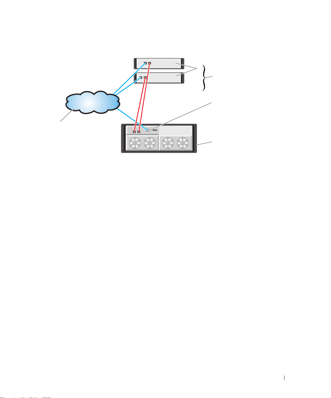
Figure 2-1. One or Two Direct-Attached Servers (or Two-Node Cluster), Single-Path Data, Single Controller (Simplex)
2
1
Management traffic
3
5
4
1 standalone (one or
two) host server
4 MD3000i RAID
Enclosure (single
controller)
2 two-node cluster 3 Ethernet
management port
5 corporate, public or
private network
Hardware Installation 11
Page 12
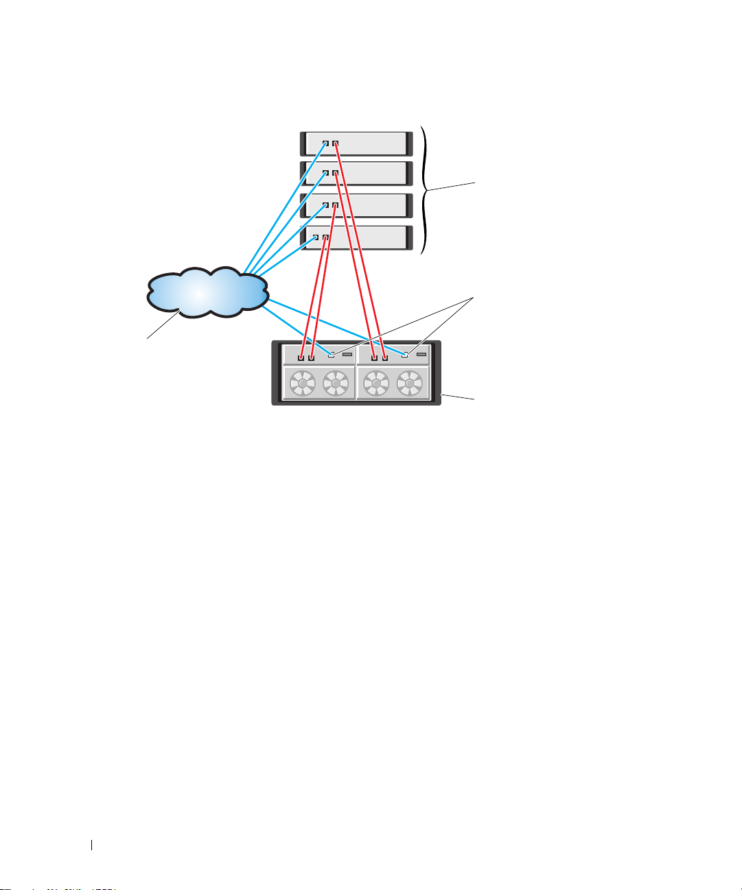
Figure 2-2. Up to Four Direct-Attached Servers, Single-Path Data, Dual Controllers (Duplex)
1
Management traffic
2
4
3
1 standalone (up to
four) host server
4 corporate, public or
private network
2 Ethernet management
port (2)
3 MD3000i RAID
Enclosure (dual
controllers)
Dual Path Data Configuration
In Figure 2-3, up to two servers are directly attached to the MD3000i RAID controller module. If the host
server has a second Ethernet connection to the array, it can be attached to the iSCSI ports on the array’s
second controller. This configuration provides improved availability by allowing two separate physical
paths for each host, which ensures full redundancy if one of the paths fail.
12 Hardware Installation
Page 13
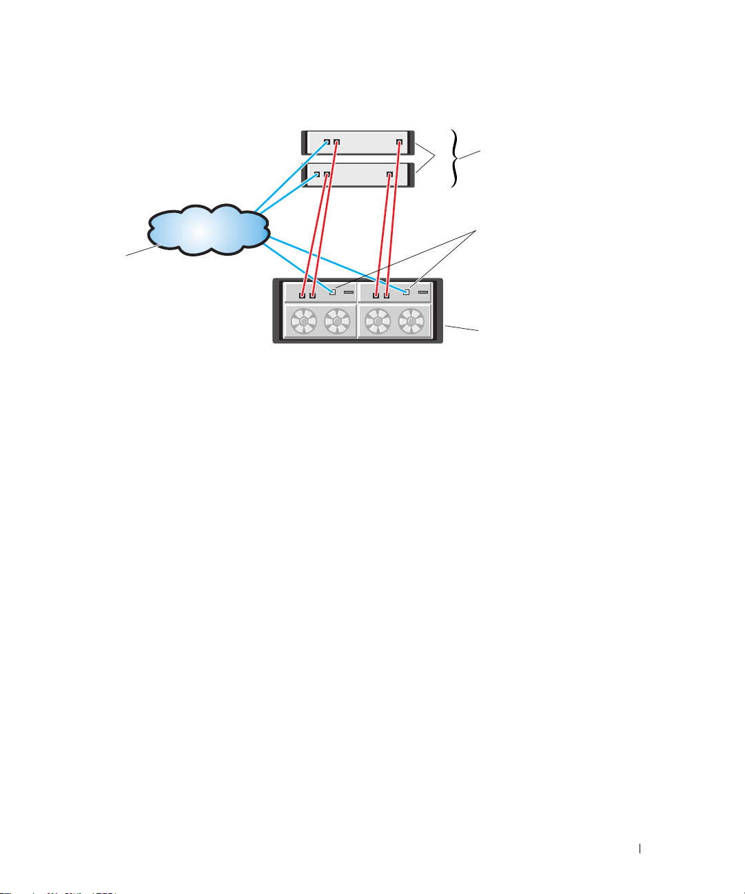
Figure 2-3. One or Two Direct-Attached Servers (or Two-Node Cluster), Dual-Path Data, Dual Controllers (Duplex)
1
5
1 standalone (one or
two) host server
4 MD3000i RAID
Enclosure (dual
controllers)
2 two-node cluster 3 Ethernet
5 corporate, public or
private network
2
3
4
management port
(2)
Network-Attached Solutions
You can also cable your host servers to the MD3000i RAID controller iSCSI ports through an IP storage
area network (SAN) industry-standard 1GB Ethernet switch. By using an IP SAN "cloud" Ethernet
switch, the MD3000i RAID controller can support up to 16 hosts simultaneously with multiple
connections per session. This solution supports either single- or dual-path data configurations, as well as
either single or dual controller modules.
Figure 2-4 shows how up to 16 standalone servers can be attached (via multiple sessions) to a single
MD3000i RAID controller module through a network. Hosts that have a second Ethernet connection to
the network allow two separate physical paths for each host, which ensures full redundancy if one of the
paths fail. Figure 2-5 shows how the same number of hosts can be similarly attached to a dual MD3000i
RAID controller array configuration.
Hardware Installation 13
Page 14
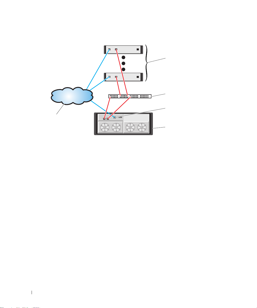
Figure 2-4. Up to 16 SAN-Configured Servers, Single-Path Data, Single Controller (Simplex)
1
2
3
5
4
1 up to 16 standalone
host servers
4 MD3000i RAID
Enclosure (single
controller)
2 IP SAN (Gigabit
Ethernet switch)
5 corporate, public or
private network
3 Ethernet
management port
14 Hardware Installation
Page 15
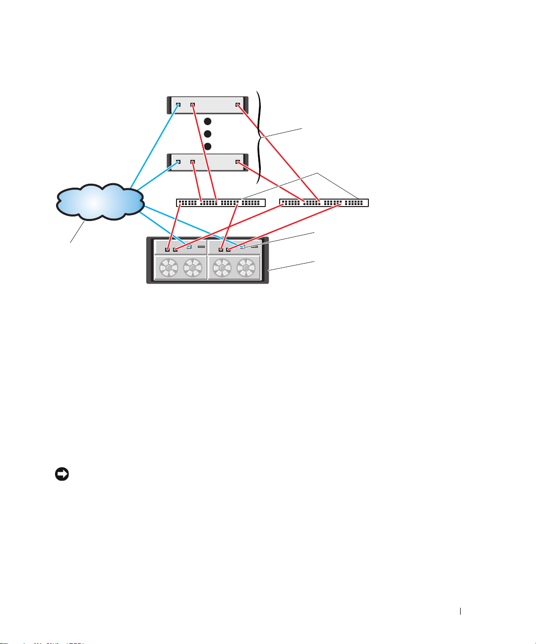
Figure 2-5. Up to 16 Dual SAN-Configured Servers, Dual-Path Data, Dual Controllers (Duplex)
1
2
3
5
4
1 up to 16 standalone
host servers
4 MD3000i RAID
Enclosure (dual
controllers)
2 IP SAN (dual Gigabit
Ethernet switches)
5 corporate, public or
private network
3 Ethernet
management port
(2)
Attaching MD1000 Expansion Enclosures
One of the features of the MD3000i is the ability to add up to two MD1000 expansion enclosures for
additional capacity. This expansion increases the maximum physical disk pool to 45 3.5" SAS and/or
SATA II physical disks.
As described in the following sections, you can expand with either a brand new MD1000 or an MD1000
that has been previously configured in a direct-attach solution with a PERC 5/E system.
NOTICE: Ensure that all MD1000 expansion enclosures being connected to the MD3000i are first updated to the
latest Dell MD1000 EMM Firmware (available from support.dell.com). Dell MD1000 EMM Firmware versions prior to
A03 are not supported in an MD3000i array; attaching an MD1000 with unsupported firmware causes an uncertified
condition to exist on the array. See the following procedure for more information.
Hardware Installation 15
Page 16

Expanding with Previously Configured MD1000 Enclosures
Use this procedure if your MD1000 is now directly attached to and configured on a Dell PERC 5/E
system. Data from virtual disks created on a PERC 5 SAS controller cannot be directly migrated to an
MD3000i or to an MD1000 expansion enclosure connected to an MD3000i.
NOTICE: If an MD1000 that was previously attached to PERC 5 SAS controller is used as an expansion enclosure
to an MD3000i, the physical disks of the MD1000 enclosure will be reinitialized and data will be lost. All data on the
MD1000 must be backed up before attempting the expansion.
Perform the following steps to attach previously configured MD1000 expansion enclosures to the MD3000i:
Back up all data on the MD1000 enclosure(s).
1
2
While the enclosure is still attached to the PERC 5 controller, upgrade the MD1000 firmware to
version A03 or above. Windows systems users can reference the
users can reference the
3
Before adding the MD1000 enclosure(s), make sure the MD3000i software is installed and up to date.
For more information, refer to the
support.dell.com
a
Install or update (to the latest version available on
.
DUP.bin
package.
Dell™ PowerVault™ MD3000i Support Matrix
support.dell.com
each host server. Install or update (to the latest version available on
multipath drivers on each host server. The multipath drivers are bundled with Modular Disk
Storage Management install. On Windows systems, the drivers are automatically installed when a
Full or Host selection is made.
b
Using the MD Storage Manager, update the MD3000i RAID controller firmware to the latest
version available on
Controller Module Firmware
RAID Controller Module NVSRAM
4
Stop I/O and turn off all systems:
a
Stop all I/O to the array and turn off affected host systems attached to the MD3000i.
b
Turn off the MD3000i.
c
Turn off the MD1000 enclosure(s).
5
Referencing the applicable configuration for your rack (Figure 2-1 through Figure 2-5), cable the
support.dell.com (Support→
) and the NVSRAM (
).
Download Firmware→
Support→
MD1000 enclosure(s) to the MD3000i.
DUP.exe
package; for Linux kernels,
available on
) the MD Storage Manager on
support.dell.com
Download RAID
Download Firmware→
) the
Download
16 Hardware Installation
Page 17

6
Turn on attached units:
a
Turn on the MD1000 expansion enclosure(s). Wait for the enclosure status LED to light blue.
b
Turn on the MD3000i and wait for the status LED to indicate that the unit is ready:
• If the status LEDs light a solid amber, the MD3000i is still coming online.
• If the status LEDs are blinking amber, there is an error that can be viewed using the
MD Storage Manager.
• If the status LEDs light a solid blue, the MD3000i is ready.
c
After the MD3000i is online and ready, turn on any attached host systems.
7
After the MD1000 is configured as the expansion enclosure to the MD3000i, restore the data that was
backed up in step 1.
After they are online, the MD1000 enclosures are available for use within the MD3000i system.
Expanding with New MD1000 Enclosures
Perform the following steps to attach new MD1000 expansion enclosures to the MD3000i:
1
Before adding the MD1000 enclosure(s), make sure the MD3000i software is installed and up to date.
For more information, refer to the
support.dell.com
a
Install or update (to the latest version available on
.
each host server.
b
Install or update (to the latest version available on
each host server.
c
Using the MD Storage Manager, update the MD3000i RAID controller firmware
(
Support→Download Firmware→
NVSRAM (
2
Stop I/O and turn off all systems:
a
Stop all I/O to the array and turn off affected host systems attached to the MD3000i.
b
Turn off the MD3000i.
c
Turn off any MD1000 enclosures in the affected system.
3
Referencing the applicable configuration for your rack (Figure 2-1 through Figure 2-5), cable the
Support→
MD1000 enclosure(s) to the MD3000i.
Dell™ PowerVault™ MD3000i Support Matrix
support.dell.com
support.dell.com
Download RAID Controller Module Firmware
Download Firmware→
Download RAID Controller Module NVSRAM
available on
) the MD Storage Manager on
) the multipath drivers on
) and the
).
Hardware Installation 17
Page 18

4
Turn on attached units:
a
Turn on the MD1000 expansion enclosure(s). Wait for the enclosure status LED to light blue.
b
Turn on the MD3000i and wait for the status LED to indicate that the unit is ready:
• If the status LEDs light a solid amber, the MD3000i is still coming online.
• If the status LEDs are blinking amber, there is an error that can be viewed using the
MD Storage Manager.
• If the status LEDs light a solid blue, the MD3000i is ready.
c
After the MD3000i is online and ready, turn on any attached host systems.
5
Using the MD Storage Manager, update all attached MD1000 firmware if it is out of date:
a
Select
b
Check the
Support→
Download Firmware→
Select All
check box so that all attached MD1000 enclosures are updated at the same
Download Environmental (EMM) Card Firmware
time (each takes approximately 8 minutes to update).
.
18 Hardware Installation
Page 19

Software Installation
The MD3000i Resource CD contains all documentation pertinent to MD3000i hardware and
MD Storage Manager software. It also includes software and drivers for both Linux and
Microsoft
The MD3000i Resource CD contains a readme.txt file covering changes to the software, updates,
fixes, patches, and other important data applicable to both Linux and Windows operating systems.
The readme.txt file also specifies requirements for accessing documentation, information regarding
versions of the software on the CD, and system requirements for running the software.
For more information on supported hardware and software for Dell™ PowerVault™ systems, refer to
the Dell™ PowerVault™ MD3000i Support Matrix located at support.dell.com.
Dell recommends installing all the latest updates available at support.dell.com.
System Assembly and Startup
Use the following procedure to assemble and start your system for the first time:
1
2
3
4
5
®
Windows® operating systems.
Install the NIC(s) in each host server that you attach to the MD3000i Storage Array, unless the
NIC was factory installed. For general information on setting up your IP addresses, see
for Configuring Your Network for iSCSI
Cable the storage array to the host server(s), either directly or via a switch.
Cable the Ethernet management ports on the storage array to either the management network
(iSCSI-attached host server) or dedicated management station (non-iSCSI).
Power on the storage array and wait for the status LED to turn blue.
Start up each host server that is cabled to the storage array.
.
Guidelines
Install the iSCSI Initiator Software (iSCSI-attached Host Servers Only)
To configure iSCSI later in this document (see "Array Setup and iSCSI Configuration"), you must
install the Microsoft iSCSI initiator on any host server that will access your storage array before you
install the MD Storage Manager software.
NOTE: Windows Server® 2008 contains a built-in iSCSI initiator. If your system is running Windows
Server 2008, you do not need to install the iSCSI initiator as shown in this section. Skip directly to "Installing
MD Storage Software."
Software Installation 19
Page 20

Depending on whether you are using a Windows Server 2003 operating system or a Linux operating
system, refer to the following steps for downloading and installing the iSCSI initiator.
Installing the iSCSI Initiator on a Windows Host Server
1
Refer to the
Dell™ PowerVault™ MD3000i Support Matrix
on
support.dell.com
for the latest version
and download location of the Microsoft iSCSI Software Initiator software.
2
From the host server, download the iSCSI Initiator software.
3
Once the installation begins and the
Initiator Service
4
DO NOT select
NOTICE: Make sure the Microsoft MPIO Multitpathing Support for iSCSI option is NOT selected. Using this option
will cause the iSCSI initiator setup to function improperly.
5
Accept the license agreement and finish the install.
NOTE: If you are prompted to do so, reboot your system.
and
Software Initiator
Microsoft MPIO Multitpathing Support for iSCSI
Microsoft iSCSI Initiator Installation
.
.
setup panel appears, select
Installing the iSCSI Initiator on a Linux Host Server
Follow the steps in this section to install the iSCSI initiator on a Linux server.
NOTE: All appropriate Linux iSCSI initiator patches are installed using the MD3000i Resource CD during MD
Storage Manager Software installation.
Installing the iSCSI Initiator on a RHEL 4 System
You can install the iSCSI initiator software on Red Hat® Enterprise Linux® 4 systems either during or
after operating system installation.
To install the iSCSI initiator during RHEL 4 installation:
1
When the
to be installed
2
In the
Package Installation Defaults
Servers
option. Click
list, select the
Next
Network Servers
screen is displayed, select the
to go to the
Server applications.
3
Select the
4
Click OK, then
To install the iSCSI initiator after RHEL 4 installation:
1
From the desktop, click
Group Selection
2
In the
iscsi-initiator-utils - iSCSI daemon and utility programs
Next
to continue with the installation.
Applications→ System Settings→ Add Remove Applications
screen is displayed.
Servers
list, select the
Network Servers
Server applications.
20 Software Installation
Package Group Selection
package and click
package and click
Details
Details
Customize the set of Packages
screen.
to display a list of Network
option.
. The
Package
to display a list of Network
Page 21

3
Select the
4
Click
Installing the iSCSI Initiator on a RHEL 5 System
iscsi-initiator-utils - iSCSI daemon and utility programs
Close
, then
Update
.
NOTE: Depending upon your installation method, the system will ask for the required source to install the
package.
option.
You can install the iSCSI initiator software on Red Hat Enterprise Linux 5 systems either during or after
operating system installation. With this version of the Linux software, you can also elect to install the
iSCSI initiator after the operating system installation via the command line.
To install the iSCSI initiator during RHEL 5 installation:
1
When the
2
Click
3
Select
4
Click
5
Select the
6
Click OK, then
To install the iSCSI initiator after RHEL 5 installation:
1
From the desktop, select
Package Installation Defaults
Next
to go to the
Base System
Optional Packages
iscsi-initiator-utils
Next
Package Group Selection
, then select the
.
option.
to continue with the installation.
Applications→ Add/Remove Software
screen is displayed, select the
screen.
Base
option.
Customize now
. The
Package Manager
option.
screen is
displayed.
2
In the
Package Manager
3
Search for
4
When it is displayed, select the
5
Click
iscsi-initiator-utils
Apply
.
screen, select the
iscsi-initiator-utils
Search
.
tab.
option.
NOTE: Depending upon your installation method, the system will ask for the required source to install the
package.
NOTE: This method might not work if network access is not available to a Red Hat Network repository.
To install the iSCSI initiator after RHEL 5 installation via the command line:
Insert the RHEL 5 installation CD 1 or DVD. If your media is not automounted, you must manual
1
mount it. The
2
Run the following command:
iscsi-initiatorutils.rpm
file is located in the Server or Client subdirectory.
rpm -i /path/to/media/Server/iscsi-initiatorutils.rpm
Software Installation 21
Page 22

Installing the iSCSI Initiator on a SLES 9 System
You can install the iSCSI initiator software on SUSE® Linux Enterprise Servers (SLES) 9 SP3 systems
either during or after operating system installation.
To install the iSCSI initiator during SLES 9 installation:
1
At the
YaST Installation Settings
2
Click
3
4
Software
Select
Various Linux Tools
Click
Accept
, then select
.
If a dependencies window is displayed, click
To install the iSCSI initiator after SLES 9 installation:
1
From the
2
Select
3
In the Search box, enter
4
When the
5
Click on
6
If no dependencies are found, click
Installing the iSCSI Initiator on a SLES 10 SP1 System
Start
menu, select
Software
, then
Install and Remove Software
linux-iscsi
linux-iscsi
module is displayed, select it.
Check Dependencies
screen, click
Detailed Selection
, then select
System YaST
Change
to see a complete list of packages.
linux-iscsi
Continue
.
.
.
and proceed with the installation.
.
.
to determine if any dependencies exist.
Accept
.
You can install the iSCSI initiator software on SUSE Linux Enterprise Server Version 10 systems either
during or after operating system installation.
To install the iSCSI initiator during SLES 10 SP1 installation:
1
At the
YaST Installation Settings
2
Click
Software
3
In the Search box, enter
4
When the
5
Click
Accept
6
If a dialog box regarding dependencies appears, click
Installing the iSCSI initiator after SLES 10 SP1 installation:
1
Select
Desktop→ YaS T→ Software→ Software Management
2
Select
Search
3
In the Search box, enter
, then select
open-iscsi
.
.
iscsi
and
yast2-iscsi-client
iscsi
Search
.
.
screen, click
.
modules are displayed, select them.
Change
22 Software Installation
.
Continue
.
and proceed with installation.
Page 23

4
When the
5
Click
open-iscsi
Accept
and
yast2-iscsi-client
modules are displayed, select them.
.
Installing MD Storage Software
The MD3000i Storage Software provides the host-based storage agent, multipath driver, and MD
Storage Manager application used to operate and manage the storage array solution. The MD Storage
Manager application is installed on a host server to configure, manage, and monitor the storage array.
When installing from the CD, three installation types are available:
•
Typical (Full installation)
software. It includes the necessary host-based storage agent, multipath driver, and MD Storage
Manager software. Select this option if you plan to use MD Storage Manager on the host server to
configure, manage, and monitor the storage array.
•
Management Station
to configure, manage, and monitor the storage array. Select this option if you plan to us MD Storage
Manager to manage the storage array from a standalone system that is connected to the storage
array only via the Ethernet management ports.
•
Host
— This package installs the necessary storage agent and multipath driver on a host server
connected to the storage array. Select this option on all host servers that are connected to a storage
array but will NOT use MD Storage Manager for any storage array management tasks.
NOTE: Dell recommends using the Host installation type if the host server is running Windows Server 2008
Core version.
— This package installs both the management station and host server
—
This package installs the MD Storage Manager software, which is needed
Installing MD Storage Software on an iSCSI-attached Host Server (Windows)
To install MD Storage Manager on a Windows system, you must have administrative privileges to install
MD Storage Manager files and program packages to the C:\Program Files\Dell\MD Storage Manager
directory.
NOTE: A minimum version of the Storport driver must be installed on the host server before installing the MD
Storage Manager software. A hotfix with the minimum supported version of the Storport driver is located in the
\windows\Windows_2003_2008\hotfixes directory on the MD3000i Resource CD. The MD Storage Manager
installation will test for the minimum Storport version and will require you to install it before proceeding.
Complete the following steps to install MD Storage Manager on an iSCSI-connected host server:
1
Close all other programs before installing any new software.
2
Insert the CD, if necessary, and navigate to the main menu.
NOTE: If the host server is running Windows Server 2008 Core version, navigate to the CD drive and run the
setup.bat utility.
3
From the main menu, select
The Installation Wizard appears.
Install MD3000i Storage Software
.
Software Installation 23
Page 24

4
Click
Next
.
5
Accept the terms of the License Agreement, and click
Next
.
The screen shows the default installation path.
6
Click
Next
to accept the path, or enter a new path and click
7
Select an installation type:
Next
.
• Typical (Full installation) — This package installs both the management station and host software.
It includes the necessary host-based storage agent, multipath driver, and MD Storage Manager
software. Select this option if you plan to use MD Storage Manager on the host server to configure,
manage, and monitor the storage array.
OR
• Host — This package installs the necessary storage agent and multipath driver on a host server
connected to the storage array. Select this option on all hosts that are connected to a storage array
but will NOT use MD Storage Manager for any storage array management tasks.
NOTE: Dell recommends using the Host installation type if the host server is running Windows Server 2008
Core version.
8
Click
Next
.
9
If the
Overwrite Warning
dialog appears, click OK. The software currently being installed
automatically replaces any existing versions of MD Storage Manager.
10
If you selected Typical (full) installation in step 6, a screen appears asking whether to restart the event
monitor automatically or manually after rebooting. You should configure only one system (either a host
or a management station) to automatically restart the event monitor.
NOTE: The event monitor notifies the administrator of problem conditions with the storage array. MD Storage
Manager can be installed on more than one system, but running the event monitor on multiple systems can
cause multiple alert notifications to be sent for the same error condition. To avoid this issue, enable the event
monitor only on a single system that monitors your storage arrays. For more information on alerts, the event
monitor, and manually restarting the event monitor, see the User’s Guide.
11
The
Pre-Installation Summary
space, and the available disk space. If the installation path is correct, click
12
When the installation completes, click
13
A screen appears asking if you want to restart the system now. Select
system myself
14
If you are setting up a cluster host, double-click the
in the
windows\utility
each node.
NOTE: Windows clustering is only supported on Windows Server 2003 and Windows Server 2008.
24 Software Installation
screen appears, showing the installation destination, the required disk
Install
.
Done
.
No, I will restart my
.
MD3000i Stand Alone to Cluster.reg
file located
directory of the MD3000i Resource CD. This merges the file into the registry of
Page 25

If you are reconfiguring a cluster node into a stand alone host, double-click the
Stand Alone.reg
file located in the
windows\utility
directory of the MD3000i Resource CD. This
MD3000i Cluster to
merges the file into the host registry.
NOTE: These registry files set the host up for the correct failback operation.
15
If you have third-party applications that use the Microsoft Volume Shadow-copy Service (VSS) or Virtual
Disk Service (VDS) Application Programming Interface (API), install the VDS_VSS package located in
the
windows\VDS_VSS
directory on the MD3000i Resource CD. Separate versions for 32-bit and 64-bit
operating systems are provided. The VSS and VDS provider will engage only if it is needed.
16
Set the path for the command line interface (CLI), if required. See the
MD Storage Manager CLI Guide
for more information.
17
Install MD Storage Manager on all other Windows hosts attached to the MD3000i array.
18
If you have not yet cabled your MD3000i Storage Array, do so at this time.
19
After the MD3000i has initialized, reboot each host attached to the array.
NOTE: If you are not installing MD Storage Manager directly from the Resource CD (for example, if you are instead
installing MD Storage Manager from a shared network drive), you must manually apply iSCSI updates to the
Windows system registry. To apply these updates, go to the \windows\Windows_2003_2008\iSCSI_reg_changer
directory on the Resource CD and run the iSCSi_reg_changer_Win2k3.bat or iSCSi_reg_changer_Win2k8.bat file.
The iSCSI Initiator must be installed before you make these updates.
Installing MD Storage Software on an iSCSI-attached Host Server (Linux)
MD Storage Manager can be installed and used only on Linux distributions that utilize the RPM Package
Manager format, such as Red Hat
/opt/dell/mdstoragemanager directory.
®
or SUSE®. The installation packages are installed by default in the
NOTE: Root privileges are required to install the software.
Follow these steps to install MD Storage Manager software on an iSCSI-connected host server:
1
Close all other programs before installing any new software.
2
Insert the CD. For some Linux installations, when you insert a CD into a drive, a screen appears asking
Yes
if you want to run the CD. Select
script in the top directory or, from within a terminal window, run
if the screen appears. Otherwise, double-click on the
./install.sh
from the
linux
on the CD.
NOTE: On RHEL 5 operating systems, CDs are automounted with the -noexec mount option. This option does
not allow you to run any executable directly from the CD. To complete this step, you must unmount the CD,
then manually remount it. Then, you can run these executables. The command to unmount the CD-ROM is:
umount CD_device_node
The command to manually mount CD is:
mount CD_device_node mount_directory
Software Installation 25
autorun
directory
Page 26

3
At the CD main menu, type
2
and press
Enter
.
The installation wizard appears.
4
Click
Next
.
5
Accept the terms of the License Agreement and click
6
Select an installation type:
Next
.
• Typical (Full installation) — This package installs both the management station and host options.
It includes the necessary host-based storage agent, multipath driver, and MD Storage Manager
software. Select this option if you plan to use MD Storage Manager on the host server to configure,
manage, and monitor the storage array.
OR
• Host — This package installs the necessary storage agent and multipath driver on a host server
connected to the storage array. Select this option on all hosts that are connected to a storage array
but will NOT use MD Storage Manager for any storage array management tasks.
7
Click
Next
.
8
If the
Overwrite Warning
dialog appears, click OK. The software currently being installed
automatically replaces any existing versions of MD Storage Manager.
9
The
Multipath Warning
driver. If this screen appears, click
dialog box may appear to advise that this installation requires an RDAC MPP
OK
. Installation instructions for the RDAC MPP driver are given in
step 13.
10
If you selected Typical (full) installation in step 6, a screen appears asking whether to restart the event
monitor automatically or manually after rebooting. You should configure only one system (either a host
or a management station) to automatically restart the event monitor.
NOTE: The event monitor notifies the administrator of problem conditions with the storage array. MD Storage
Manager can be installed on more than one system, but running the event monitor on multiple systems can
cause multiple alert notifications to be sent for the same error condition. To avoid this issue, enable the event
monitor only on a single system which monitors your MD3000i arrays. For more information on alerts, the
event monitor, and manually restarting the event monitor, see the User’s Guide.
11
The
Pre-Installation Summary
space, and the available disk space. If the installation path is correct, click
12
When the installation completes, click
13
At the
install the multi-pathing driver [y/n]?
14
When the RDAC driver installation is complete, quit the menu and restart the system.
15
Install MD Storage Manager on all other hosts attached to the MD3000i array.
16
Reboot each host attached to the array.
26 Software Installation
screen appears showing the installation destination, the required disk
Install
.
Done
.
prompt, answer y (yes).
Page 27

Installing a Dedicated Management Station (Windows and Linux)
Optionally, you can manage your storage array over the network via a dedicated system attached to the
array via the Ethernet management port. If you choose this option, follow these steps to install MD
Storage Manager on that dedicated system.
1
(Windows) From the CD main menu, select
2
(Linux) From the CD main menu, type
The Installation Wizard appears.
3
Click
Next
.
4
Accept the terms of the License Agreement and click
5
Click
Next
to accept the default installation path (Windows), or enter a new path and click
6
Select
Management Station
as the installation type. This option installs only the MD Storage
Manager software used to configure, manage and monitor a MD3000i storage array.
7
Click
Next
.
8
If the
Overwrite Warning
dialog appears, click OK. The software currently being installed
automatically replaces any existing versions of MD Storage Manager.
9
A screen appears asking whether to restart the event monitor automatically or manually after
rebooting. You should configure only one system (either a host or a management station) to
automatically restart the event monitor.
NOTE: The event monitor notifies the administrator of problem conditions with the storage array. MD Storage
Manager can be installed on more than one system, but running the event monitor on multiple systems can
cause multiple alert notifications to be sent for the same error condition. To avoid this issue, enable the event
monitor only on a single system that monitors your MD3000i arrays. For more information on alerts, the event
monitor, and manually restarting the event monitor, see the MD Storage Manager User’s Guide.
10
The
Pre-Installation Summary
screen appears showing the installation destination, the required disk
space, and the available disk space. If the installation path is correct, click
11
When the installation completes, click
A screen appears asking if you want to restart the system now.
Install MD3000i Storage Software
2
and press <Enter>.
Next
.
Done
.
Install
.
Next
.
.
12
Restart the system.
13
Set the path for the command line interface (CLI), if required. See the
Guide
for more information.
MD Storage Manager CLI
Software Installation 27
Page 28

Documentation for Windows Systems
Viewing Resource CD Contents
1
Insert the CD. If autorun is disabled, navigate to the CD and double-click
NOTE: On a server running Windows Server 2008 Core version, navigate to the CD and run the setup.bat
utility. Only the MD3000i Readme can be viewed on Windows Server 2008 Core versions. Other MD3000i
documentation cannot be viewed or installed.
A screen appears showing the following items:
a
View MD3000i Readme
b
Install MD3000i Storage Software
c
Install MD3000i Documentation
d
iSCSI Setup Instructions
2
To view the
The
readme.txt
3
Close the window after viewing the file to return to the menu screen.
4
To view the manuals from the CD, open the HTML versions from the
Installing the Manuals
1
Insert the CD, if necessary, and select
A second screen appears.
readme.txt
file, click the first bar.
file appears in a separate window.
Install MD3000i Documentation
setup.exe
/docs/
folder on the CD.
in the main menu.
.
2
Click
Next
.
3
Accept the License Agreement and click
4
Select the installation location or accept the default and click
5
Click
Install
.
The installation process begins.
6
When the process completes, click
7
To view the installed documents, go to
NOTE: The MD3000i Documentation cannot be installed on Windows Server 2008 Core versions.
28 Software Installation
Next
.
Finish
to return to the main menu.
My Computer
and navigate to the installation location.
Next
.
Page 29

Documentation for Linux Systems
Viewing Resource CD Contents
1
Insert the CD.
For some Linux distributions, a screen appears asking if you want to run the CD. Select
screen appears. If no screen appears, execute
2
A menu screen appears showing the following items:
1 View MD3000i Readme
2 Install MD3000i Storage Software
3 Install Multi-pathing Driver
4 Install MD3000i Documentation
5 View MD3000i Documentation
6 iSCSI Setup Instructions
7 Dell Support
8 View End User License Agreement
./install.sh
within the
linux
folder on the CD.
Yes
if the
If you want to view the
3
file appears in a separate window. Close the window after viewing the file to return to the menu screen.
The
4
To view another document, type
A second menu screen appears with the following selections:
MD3000i Owner's Manual
MD3000i Installation Guide
MD Storage Manager CLI Guide
MD Storage Manager User's Guide
NOTE: To view the documents from the CD, you must have a web browser installed on the system.
5
Type the number of the document you want and press <Enter>.
The document opens in a browser window.
6
Close the document when you are finished. The system returns to the documentation menu described
in step 4.
7
Select another document or type
menu screen.
readme.txt
5
q
file, type
1
and press <Enter>.
and press <Enter>.
and press <Enter> to quit. The system returns to the main
Software Installation 29
Page 30

Installing the Manuals
1
Insert the CD, if necessary, and from the menu screen, type
2
A screen appears showing the default location for installation. Press <Enter> to accept the path
shown, or enter a different path and press <Enter>.
3
When installation is complete, press any key to return to the main menu.
4
To view the installed documents, open a browser window and navigate to the installation directory.
5
and press <Enter>.
30 Software Installation
Page 31

Array Setup and iSCSI Configuration
To use the storage array, you must configure iSCSI on both the host server(s) and the storage array.
Step-by-step instructions for configuring iSCSI are described in this section. However, before
proceeding here, you must have already installed the Microsoft iSCSI initiator and the MD Storage
Manager software. If you have not, refer to Software Installation and complete those procedures
before attempting to configure iSCSI.
NOTE: Although some of these steps shown in this section can be performed in MD Storage Manager
from a management station, the iSCSI initiator must be installed and configured on each host server.
Before You Start
Before you begin configuring iSCSI, you should fill out the iSCSI Configuration Worksheet
(Table 4-2 and Table 4-3). Gathering this type of information about your network prior to starting
the configuration steps should help you complete the process in less time.
NOTE: If you are running Windows Server 2008 and elect to use IPv6, use Table 4-3 to define your
settings on the host server and storage array controller iSCSI ports. IPv6 is not supported on storage
array controller management ports.
Terminology
The table below outlines the terminology used in the iSCSI configuration steps later in this section.
Table 4-1. Standard Terminology Used in iSCSI Configuration
Term Definition
CHAP (Challenge Handshake
Authentication Protocol)
host or host server A server connected to the storage array via iSCSI ports.
host server port iSCSI port on the host server used to connect it to the storage
iSCSI initiator The iSCSI-specific software installed on the host server that
An optional security protocol used to control access to an iSCSI
storage system by restricting use of the iSCSI data ports on both
the host server and storage array. For more information on the
types of CHAP authentication supported, see Understanding
CHAP Authentication.
array.
controls communications between the host server and the storage
array.
Setting Up Your iSCSI Storage Array 31
Page 32

Table 4-1. Standard Terminology Used in iSCSI Configuration (continued)
Term Definition
iSCSI host port The iSCSI port (two per controller) on the storage array.
iSNS (Microsoft Internet Storage
Naming Service)
management station The system from which you manage your host server/storage array
storage array The enclosure containing the storage data accessed by the host
target An iSCSI port on the storage array that accepts and responds to
An automated discovery, management and configuration tool
used by some iSCSI devices.
configuration.
server.
requests from the iSCSI initiator installed on the host server.
iSCSI Configuration Worksheet
The iSCSI Configuration Worksheet (Table 4-2 or Table 4-3) helps you plan your configuration.
Recording host server and storage array IP addresses at a single location will help you configure your
setup faster and more efficiently.
Guidelines for Configuring Your Network for iSCSI provides general network setup guidelines for both
Windows and Linux environments. It is recommended that you review these guidelines before
completing the worksheet.
32 Setting Up Your iSCSI Storage Array
Page 33

Table 4-2. iSCSI Configuration Worksheet (IPv4 settings)
A
B
192.168.130.101 (In 0 default)
192.168.131.101 (In 1 default)
192.168.128.101 (Mgmt network port)
If you need additional space for more than one host server, use an additional sheet.
A
iSCSI port 1
iSCSI port 2
iSCSI port 3
iSCSI port 4
Management port
Static IP address (host server)
____ . ____ . ____ . ____
____ . ____ . ____ . ____
____ . ____ . ____ . ____
____ . ____ . ____ . ____
____ . ____ . ____ . ____
cntl. 0
cntl. 1
host server
MD3000i
192.168.128.102
(Mgmt network port)
192.168.131.102 (In 1 default)
192.168.130.102 (In 0 default)
Subnet
(should be different for each NIC)
____ . ____ . ____ . ____
____ . ____ . ____ . ____
____ . ____ . ____ . ____
____ . ____ . ____ . ____
____ . ____ . ____ . ____
Mutual CHAP
Secret
Target CHAP
Secret
Default gateway
____ . ____ . ____ . ____
____ . ____ . ____ . ____
____ . ____ . ____ . ____
____ . ____ . ____ . ____
____ . ____ . ____ . ____
Management port
B
Static IP address (storage array)
iSCSI controller 0, In 0
iSCSI controller 0, In 1
Management port, cntrl. 0
iSCSI controller 1, In 0
iSCSI controller 1, In 1
Management port, cntrl. 1
____ . ____ . ____ . ____
____ . ____ . ____ . ____
____ . ____ . ____ . ____
____ . ____ . ____ . ____
____ . ____ . ____ . ____
____ . ____ . ____ . ____
____ . ____ . ____ . ____
____ . ____ . ____ . ____
Subnet
____ . ____ . ____ . ____
____ . ____ . ____ . ____
____ . ____ . ____ . ____
____ . ____ . ____ . ____
____ . ____ . ____ . ____
____ . ____ . ____ . ____
Setting Up Your iSCSI Storage Array 33
____ . ____ . ____ . ____
Default gateway
____ . ____ . ____ . ____
____ . ____ . ____ . ____
____ . ____ . ____ . ____
____ . ____ . ____ . ____
____ . ____ . ____ . ____
____ . ____ . ____ . ____
Page 34

Table 4-3. iSCSI Configuration Worksheet (IPv6 settings)
A
cntl. 0
B
host server
cntl. 1
MD3000i
If you need additional space for more than one host server, use an additional sheet.
Host iSCSI port 1
A
Link Local IP Address
Routable IP Address
Subnet Prefix
Gateway
B
________________________
________________________
________________________
________________________
iSCSI controller 0, In 0
IP Address
Routable IP Address 1
Routable IP Address 2
Router IP Address
iSCSI controller 0, In 1
IP Address
Routable IP Address 1
Routable IP Address 2
Router IP Address
iSCSI controller 1, In 0
IP Address
Routable IP Address 1
Routable IP Address 2
Router IP Address
iSCSI controller 1, In 1
IP Address
Routable IP Address 1
Routable IP Address 2
Router IP Address
FE80 : 0000 : 0000 : 0000 : ____ : ____ : ____ : ____
____ : ____ : ____ : ____ : ____ : ____ : ____ : ____
____ : ____ : ____ : ____ : ____ : ____ : ____ : ____
____ : ____ : ____ : ____ : ____ : ____ : ____ : ____
FE80 : 0000 : 0000 : 0000 : ____ : ____ : ____ : ____
____ : ____ : ____ : ____ : ____ : ____ : ____ : ____
____ : ____ : ____ : ____ : ____ : ____ : ____ : ____
____ : ____ : ____ : ____ : ____ : ____ : ____ : ____
FE80 : 0000 : 0000 : 0000 : ____ : ____ : ____ : ____
____ : ____ : ____ : ____ : ____ : ____ : ____ : ____
____ : ____ : ____ : ____ : ____ : ____ : ____ : ____
____ : ____ : ____ : ____ : ____ : ____ : ____ : ____
FE80 : 0000 : 0000 : 0000 : ____ : ____ : ____ : ____
____ : ____ : ____ : ____ : ____ : ____ : ____ : ____
____ : ____ : ____ : ____ : ____ : ____ : ____ : ____
____ : ____ : ____ : ____ : ____ : ____ : ____ : ____
Host iSCSI port 2
Link Local IP Address
Routable IP Address
Subnet Prefix
Gateway
Mutual CHAP
Secret
Target CHAP
Secret
________________________
________________________
________________________
________________________
34 Setting Up Your iSCSI Storage Array
Page 35

Configuring iSCSI on Your Storage Array
The following sections contains step-by-step instructions for configuring iSCSI on your storage array.
However, before beginning, it is important to understand where each of these steps occur in relation to
your host server/storage array environment.
Table 4-4 below shows each specific iSCSI configuration step and where it occurs.
Table 4-4. Host Server vs. Storage Array
This step is performed on the HOST SERVER using
the Microsoft or Linux iSCSI Initiator:
Step 3: Perform target discovery from the iSCSI
initiator
Step 6: (Optional) Configure CHAP
authentication on the host server
Step 7: Connect to the storage array from the host
server
This step is performed on the STORAGE ARRAY
using MD Storage Manager:
Step 1: Discover the storage array
Step 2: Configure the iSCSI ports on the storage
array
Step 4: Configure host access
Step 5: (Optional) Configure CHAP
authentication on the storage array
Step 8: (Optional) Set up in-band management
Using iSNS
iSNS (Internet Storage Naming Service) Server, supported only on Windows iSCSI environments,
eliminates the need to manually configure each individual storage array with a specific list of initiators
and target IP addresses. Instead, iSNS automatically discovers, manages, and configures all iSCSI devices
in your environment.
For more information on iSNS, including installation and configuration, see www.microsoft.com.
Setting Up Your iSCSI Storage Array 35
Page 36

Step 1: Discover the Storage Array (Out-of-band management only)
Default Management Port Settings
By default, the
your storage array is unable to get IP configuration from a DHCP server, it will timeout after ten seconds
and fall back to a default static IP address. The default IP configuration is:
Controller 0: IP: 192.168.128.101 Subnet Mask: 255.255.255.0
Controller 1: IP: 192.168.128.102 Subnet Mask: 255.255.255.0
You can discover the storage array automatically or manually. Choose one and complete the steps below.
Automatic Storage Array Discovery
1
Launch MD Storage Manager.
If this is the first storage array to be set up, the
2
Choose
It may take several minutes for the discovery process to complete. Closing the discovery status window
before the discovery process completes will cancel the discovery process.
storage array
NOTE: No default gateway is set.
NOTE: If DHCP is not used, initial configuration of the management station must be performed on the same
physical subnet as the storage array. Additionally, during initial configuration, at least one network adapter
must be configured on the same IP subnet as the storage array’s default management port (192.168.128.101 or
192.168.128.102). After initial configuration (management ports are configured using MD Storage Manager),
the management station’s IP address can be changed back to its previous settings.
NOTE: This procedure applies to out-of-band management only. If you choose to set up in-band
management, you must complete this step and then refer to Step 8: (Optional) Set Up In-Band Management.
Automatic
management ports will be set to DHCP configuration. If the controller(s) on
Add New Storage Array
window appears.
and click OK.
After discovery is complete, a confirmation screen appears. Click
Manual Storage Array Discovery
1
Launch MD Storage Manager.
If this is the first storage array to be set up, the
2
Select
Manual
3
Select
Out-of-band management
storage array controller.
4
Click
Add
Out-of-band management should now be successfully configured.
After discovery is complete, a confirmation screen appears. Click
36 Setting Up Your iSCSI Storage Array
and click OK.
.
Close
to close the screen.
Add New Storage Array
window appears.
and enter the host server name(s) or IP address(es) of the iSCSI
Close
to close the screen.
Page 37

Set Up the Array
1
When discovery is complete, the name of the first storage array found appears under the
in MD Storage Manager.
2
The default name for the newly discovered storage array is
the down arrow next to that name and choose
3
Click the
information about each task, see the
Table 4-5. Initial Storage Array Setup Tasks
Tas k
Rename the storage array.
NOTE: If you need to physically
find the device, click Blink the
storage array on the Initial Setup
Tasks dialog box or click the Tools
tab and choose Blink. Lights on the
front of the storage array blink
intermittently to identify the array.
Dell recommends blinking storage
arrays to ensure that you are
working on the correct enclosure.
Initial Setup Tasks
option to see links to the remaining post-installation tasks. For more
User’s Guide.
NOTE: Before configuring the storage array, check the status icons on the Summary tab to make sure the
enclosures in the storage array are in an Optimal status. For more information on the status icons,
see Troubleshooting Tools.
Purpose Information Needed
To provide more a meaningful
name than the software-assigned
label of Unnamed.
Unnamed
Perform these tasks in the order shown in Table 4-5.
Unnamed
. If another name appears, click
in the drop-down list.
A unique, clear name with no more
than 30 characters that may include
letters, numbers, and no special
characters other than underscore (_),
minus (–), or pound sign (#).
NOTE: MD Storage Manager does not
check for duplicate names. Names are
not case sensitive.
Summary
tab
Set a storage array password. To restrict unauthorized access,
MD Storage Manager asks for a
password before changing the
configuration or performing a
destructive operation.
A case-sensitive password that meets
the security requirements of your
enterprise.
Setting Up Your iSCSI Storage Array 37
Page 38

Table 4-5. Initial Storage Array Setup Tasks (continued)
Purpose Information Needed
Tas k
Set the management port IP
addresses on each controller.
To set the management port IP
addresses to match your public
network configuration. Although
DHCP is supported, static IP
addressing is recommended.
In MD Storage Manager, select
Initial Setup Tasks
Ethernet Management Ports, then
specify the IP configuration for each
management port on the storage
array controllers.
NOTE: If you change a management
port IP address, you may need to
update your management station
configuration and/or repeat storage
array discovery.
Set up alert notifications.
Set up e-mail alerts.
Set up SNMP alerts.
NOTE: The Status area in the
Summary tab shows if alerts have
been set for the selected array.
To arrange to notify individuals (by
e-mail) and/or storage management
stations (by SNMP) when a storage
array component degrades or fails,
or an adverse environmental
condition occurs.
E-mail — Sender (sender’s SMTP
gateway and e-mail address) and
recipients (fully qualified e-mail
addresses)
SNMP — (1) A community name, a
known set of storage management
stations set by administrator as an
ASCII string in the management
console (default: "public"), and (2)
a trap destination, IP address or host
name of a management console
running an SNMP service
→
Configure
38 Setting Up Your iSCSI Storage Array
Page 39

Step 2: Configure the iSCSI Ports on the Storage Array
By default, the iSCSI ports on the storage array are set to the following IPv4 settings:
Controller 0, Port 0: IP: 192.168.130.101 Subnet Mask: 255.255.255.0 Port: 3260
Controller 0, Port 1: IP: 192.168.131.101 Subnet Mask: 255.255.255.0 Port: 3260
Controller 1, Port 0: IP: 192.168.130.102 Subnet Mask: 255.255.255.0 Port: 3260
Controller 1, Port 1: IP: 192.168.131.102 Subnet Mask: 255.255.255.0 Port: 3260
NOTE: No default gateway is set.
To configure the iSCSI ports on the storage array, complete the following steps:
1
From MD Storage Manager, click the
2
Configure the iSCSI ports on the storage array.
NOTE: Using static IPv4 addressing is recommended, although DHCP is supported.
NOTE: IPv4 is enabled by default on the iSCSI ports. You must enable IPv6 to configure IPv6 addresses.
NOTE: IPv6 is supported only on controllers that will connect to host servers running Windows Server 2008.
The following settings are available (depending on your specific configuration) by clicking the
Advanced
button:
• Virtual LAN (VLAN) support
A VLAN is a network of different systems that behave as if they are connected to the same
segments of a local area network (LAN) and are supported by the same switches and routers.
When configured as a VLAN, a device can be moved to another location without being
reconfigured. To use VLAN on your storage array, obtain the VLAN ID from your network
administrator and enter it here.
iSCSI
tab, then select
Configure iSCSI Host Ports
.
• Ethernet priority
This parameter is set to determine a network access priority.
• TCP listening port
The port number the controller on the storage array uses to listen for iSCSI logins from host server
iSCSI initiators.
NOTE: The TCP listening port for the iSNS server is the port number the storage array controller uses to
connect to an iSNS server. This allows the iSNS server to register the iSCSI target and portals of the storage
array so that the host server initiators can identify them.
• Jumbo frames
Jumbo Ethernet frames are created when the maximum transmission units (MTUs) are larger than
1500 bytes per frame. This setting is adjustable port-by-port.
3
To enable ICMP PING responses for all ports, select
4
Click OK when all iSCSI storage array port configurations are complete.
5
Test the connection by performing a ping command on each iSCSI storage array port.
Enable ICMP PING responses
Setting Up Your iSCSI Storage Array 39
.
Page 40

Step 3: Perform Target Discovery from the iSCSI Initiator
This step identifies the iSCSI ports on the storage array to the host server. Select the set of steps in one
of the following sections (Windows or Linux) that corresponds to your operating system.
If you are using Windows Server 2003 or Windows Server 2008 GUI version
1
Click
Start→
Tools
→ iSCSI Initiator
2
Click the
3
Under
storage array.
4
If the iSCSI storage array uses a custom TCP port, change the
5
Click
Advanced
•
•
•
•
NOTE: IPSec is not supported.
Click OK to exit the
Programs→
Discovery
Target Portals
and set the following values on the
Local Adapter
Source IP
Data Digest and Header Digest
information be compiled during transmission to assist in troubleshooting.
CHAP logon information
at this point, unless you are adding the storage array to a SAN that has target CHAP already
configured.
: The source IP address of the host you want to connect with.
Microsoft iSCSI Initiator
.
tab.
, click
Add
and enter the
: Must be set to
: Leave this option unselected and do not enter CHAP information
Advanced
menu, and OK again to exit the
or
Start→
IP address or DNS name
General
Microsoft iSCSI Initiator
: Optionally, you can specify that a digest of data or header
All Programs→
of the iSCSI port on the
Port
number. The default is 3260.
tab:
.
Add Target Portals
Administrative
screen.
6
To ex i t t he
If you plan to configure CHAP authentication
port at this point. Stop here and go to the next step, Step 4: Configure Host Access.
If you do not plan to configure CHAP authentication
iSCSI ports on the storage array.
Discovery
tab, click OK.
If you are using Windows Server 2008 Core Version
1
Set the iSCSI initiator service to start automatically:
sc \\<server_name> config msiscsi start= auto
Start the iSCSI service:
2
sc start msiscsi
Add a target portal:
3
iscsicli QAddTargetPortal <IP_address_of_iSCSI_port_on_storage
array>
40 Setting Up Your iSCSI Storage Array
, do not perform discovery on more than one iSCSI
, repeat step 1 thorough step 6 (above) for all
Page 41

If you are using Linux Server
Configuration of the iSCSI initiator for Red Hat® Enterprise Linux® version 4 and SUSE® Linux
Enterprise Server 9 distributions is performed by modifying the /etc/iscsi.conf file, which is installed by
default when you install MD Storage Manager. You can edit the file directly, or replace the default file
with a sample file included on the MD3000i Resource CD.
To use the sample file included on the CD:
1
Save the default
2
Copy the appropriate sample file from
3
Rename the sample file to
4
Edit the
IP addresses assigned to the iSCSI ports on your storage array:
For example, if your MD3000i has two iSCSI controllers (four iSCSI ports), you will need to add four
IP addresses:
iscsi.conf
/etc/iscsi.conf
file and replace the IP address entries shown for
file by naming it to another name of your choice.
iscsi.conf
/linux/etc
.
on the CD to
/etc/iscsi.conf
DiscoveryAddress=
.
with the
DiscoveryAddress=
DiscoveryAddress=
DiscoveryAddress=
DiscoveryAddress=
If you elect not to use the sample file on the CD, edit the existing default
in the previous example.
5
Edit (or add) the following entries to the
HeaderDigest=never
DataDigest=never
LoginTimeout=15
IdleTimeout=15
PingTimeout=5
ConnFailTimeout=144
AbortTimeout=10
ResetTimeout=30
Continuous=no
InitialR2T=no
<your_storage_array_IP_address>
<your_storage_array_IP_address>
<your_storage_array_IP_address>
<your_storage_array_IP_address>
/etc/iscsi.conf
file:
/etc/iscsi.conf
file as shown
ImmediateData=yes
MaxRecvDataSegmentLength=65536
Setting Up Your iSCSI Storage Array 41
Page 42

FirstBurstLength=262144
MaxBurstLength=16776192
Restart the iSCSI daemon by executing the following command from the console:
6
/etc/init.d/iscsi restart
Verify that the server can connect to the storage array by executing this command from a console:
7
iscsi -ls
If successful, an iSCSI session has been established to each iSCSI port on the storage array. Sample
output from the command should look similar to this:
********************************************************************
SFNet iSCSI Driver Version ...4:0.1.11-3(02-May-2006)
********************************************************************
TARGET NAME : iqn.1984-05.com.dell:powervault.6001372000f5f0e600000000463b9292
TARGET ALIAS :
HOST ID : 2
BUS ID : 0
TARGET ID : 0
TARGET ADDRESS : 192.168.0.110:3260,1
SESSION STATUS : ESTABLISHED AT Wed May 9 18:20:27 CDT 2007
SESSION ID : ISID 00023d000001 TSIH 5
********************************************************************
TARGET NAME : iqn.1984-05.com.dell:powervault.6001372000f5f0e600000000463b9292
TARGET ALIAS :
HOST ID : 3
BUS ID : 0
TARGET ID : 0
TARGET ADDRESS : 192.168.0.111:3260,1
SESSION STATUS : ESTABLISHED AT Wed May 9 18:20:28 CDT 2007
SESSION ID : ISID 00023d000002 TSIH 4
If you are using RHEL 5 or SLES 10 SP1
Configuration of the iSCSI initiator for RHEL version 5 and SLES 10 SP1 distributions is done by
modifying the /etc/iscsi/iscsid.conf file, which is installed by default when you install MD Storage
Manager. You can edit the file directly, or replace the default file with a sample file included on the
MD3000i Resource CD.
To use the sample file included on the CD:
1
Save the default
2
Copy the appropriate sample file from
3
Rename the sample file to
42 Setting Up Your iSCSI Storage Array
/etc/iscsi/iscsid.conf
iscsid.conf
file by naming it to another name of your choice.
/linux/etc
on the CD to
/etc/iscsi/iscsid.conf
.
.
Page 43

4
Edit the following entries in the
a
Edit (or verify) that the
b
Edit (or verify) that the
/etc/iscsi/iscsid.conf
node.startup = manual
file:
line is disabled.
node.startup = automatic
line is enabled. This will enable
automatic startup of the service at boot time.
c
Verify that the following time-out value is set to
144
:
node.session.timeo.replacement_timeout = 144
d
Save and close the
5
From the console, restart the iSCSI service with the following command:
/etc/iscsi/iscsid.conf
file.
service iscsi start
Verify that the iSCSI service is running during boot using the following command from the console:
6
chkconfig iscsi on
To display the available iscsi targets at the specified IP address, use the following command:
7
iscsiadm –m discovery –t st -p <
After target discovery, use the following command to manually login:
8
IP_address_of_iSCSI_port
>
iscsiadm -m node –l
This logon will be performed automatically at startup if automatic startup is enabled.
9
Manually log out of the session using the following command:
iscsiadm -m node -T <initiator_username> -p <target_ip> -u
Setting Up Your iSCSI Storage Array 43
Page 44

Step 4: Configure Host Access
This step specifies which host servers will access virtual disks on the storage array. You should perform
this step:
• before mapping virtual disks to host servers
• any time you connect new host servers to the storage array
1
Launch MD Storage Manager.
2
Click on the
3
At
Enter host name
This can be an informal name, not necessarily a name used to identify the host server to the network.
4
In the
Click
5
If your iSCSI initiator shows up in the list of
Add
click
– In Windows, the iSCSI initiator name can be found on the
Properties
– In Linux, the iSCSI initiator name can be found in the
iscsi-iname
Click
6
Choose whether or not the host server will be part of a host server group that will share access to the
same virtual disks as other host servers. Select
Click
Configure
Select host type
Next
.
Next
Next
and then
.
.
Next.
window.
command.
tab, then select
, enter the host server to be available to the storage array for virtual disk mapping.
drop-down menu, select the host type.
Otherwise, click
Configure Host Access (Manual)
Known iSCSI initiators
New
and enter the
Yes
only if the host is part of a Microsoft cluster.
iSCSI initiator name
etc/initiatorname.iscsi file
, make sure it is highlighted and
General
tab of the
.
.
iSCSI Initiator
or by using the
7
Click
Finish
.
44 Setting Up Your iSCSI Storage Array
Page 45

Understanding CHAP Authentication
Before proceeding to either Step 5: Configure CHAP Authentication on the Storage Array (optional) or
Step 6: Configure CHAP Authentication on the Host Server (optional), it would be useful to gain an
overview of how CHAP authentication works.
What is CHAP?
Challenge Handshake Authentication Protocol (CHAP) is an optional iSCSI authentication method
where the storage array (target) authenticates iSCSI initiators on the host server. Two types of CHAP are
supported: target CHAP and mutual CHAP.
Target CHAP
In target CHAP, the storage array authenticates all requests for access issued by the iSCSI initiator(s) on
the host server via a CHAP secret. To set up target CHAP authentication, you enter a CHAP secret on
the storage array, then configure each iSCSI initiator on the host server to send that secret each time it
attempts to access the storage array.
Mutual CHAP
In addition to setting up target CHAP, you can set up mutual CHAP in which both the storage array and
the iSCSI initiator authenticate each other. To set up mutual CHAP, you configure the iSCSI initiator
with a CHAP secret that the storage array must send to the host sever in order to establish a connection.
In this two-way authentication process, both the host server and the storage array are sending
information that the other must validate before a connection is allowed.
CHAP is an optional feature and is not required to use iSCSI. However, if you do not configure CHAP
authentication, any host server connected to the same IP network as the storage array can read from and
write to the storage array.
NOTE: If you elect to use CHAP authentication, you should configure it on both the storage array (using MD
Storage Manager) and the host server (using the iSCSI initiator) before preparing virtual disks to receive data.
If you prepare disks to receive data before you configure CHAP authentication, you will lose visibility to the
disks once CHAP is configured.
Setting Up Your iSCSI Storage Array 45
Page 46

CHAP Definitions
To summarize the differences between target CHAP and mutual CHAP authentication, see Table 4-6.
Table 4-6. CHAP Types Defined
CHAP Type Description
Target CHAP Sets up accounts that iSCSI initiators use to connect to the target
storage array. The target storage array then authenticates the iSCSI
initiator.
Mutual CHAP Applied in addition to target CHAP, mutual CHAP sets up an account
that a target storage array uses to connect to an iSCSI initiator. The
iSCSI initiator then authenticates the target.
How CHAP Is Set Up
The next two steps in your iSCSI configuration, Step 5: Configure CHAP Authentication on the Storage
Array (optional) and Step 6: Configure CHAP Authentication on the Host Server (optional), offer step-by-
step procedures for setting up CHAP on your storage array and host server.
46 Setting Up Your iSCSI Storage Array
Page 47

Step 5: Configure CHAP Authentication on the Storage Array (optional)
If you are configuring CHAP authentication of any kind (either target-only or target and mutual), you
must complete this step and Step 6: Configure CHAP Authentication on the Host Server (optional).
If you are not configuring any type of CHAP, skip these steps and go to Step 7: Connect to the Target
Storage Array from the Host Server.
NOTE: If you choose to configure mutual CHAP authentication, you must first configure target CHAP.
Remember, in terms of iSCSI configuration, the term target always refers to the storage array.
Configuring Target CHAP Authentication on the Storage Array
1
From MD Storage Manager, click the
Make a selection based on the following:
Table 4-7. CHAP Settings
Selection Description
None This is the default selection. If None is the only selection, the storage array will
allow an iSCSI initiator to log on without supplying any type of CHAP
authentication.
None and
CHAP
CHAP If CHAP is selected and None is deselected, the storage array will require CHAP
The storage array will allow an iSCSI initiator to log on with or without CHAP
authentication.
authentication before allowing access.
iSCSI
tab, then
Change Target Authentication
.
2
To configure a CHAP secret, select
3
Enter the
Secret
Target CHAP secret (or Generate Random Secret)
and click OK.
CHAP
and select
CHAP Secret
, confirm it in
.
Confirm Target CHAP
Although the storage array allows sizes from 12 to 57 characters, many initiators only support CHAP
secret sizes up to 16 characters (128-bit).
NOTE: Once entered, a CHAP secret is not retrievable. Make sure you record the secret in an accessible
place. If Generate Random Secret is used, copy and past the secret into a text file for future reference since
the same CHAP secret will be used to authenticate any new host servers you may add to the storage array. If
you forget this CHAP secret, you must disconnect all existing hosts attached to the storage array and repeat
the steps in this chapter to re-add them.
4
Click OK.
Setting Up Your iSCSI Storage Array 47
Page 48

Configuring Mutual CHAP Authentication on the Storage Array
The initiator secret must be unique for each host server that connects to the
be the same as the target CHAP secret.
1
From MD Storage Manager, click on the
Permissions
2
Select an initiator on the host server and click the
3
Enter the
NOTE: In some cases, an initiator CHAP secret may already be defined in your configuration. If so, use it
4
Click
NOTE: To remove a CHAP secret, you must delete the host initiator and re-add it.
.
Initiator CHAP secret
here.
Close
.
, confirm it in
iSCSI
tab, then select
CHAP Secret
Enter Mutual Authentication
.
Confirm initiator CHAP secret
storage array
, and click OK.
and must not
48 Setting Up Your iSCSI Storage Array
Page 49

Step 6: Configure CHAP Authentication on the Host Server (optional)
If you configured CHAP authentication in Step 5: Configure CHAP Authentication on the Storage Array
(optional), complete the following steps. If not, skip to Step 7: Connect to the Target Storage Array from
the Host Server.
Select the set of steps in one of the following sections (Windows or Linux) that corresponds to your
operating system.
If you are using Windows Server 2003 or Windows Server 2008 GUI version
1
Click
Start→
Tools
→
2
If you are NOT using mutual CHAP authentication:
• skip to the step 4 below
3
If you are using mutual CHAP authentication:
• click the
• select
•at
4
Click the
5
Under
The iSCSI port you configured on the storage array during target discovery should disappear. You will
reset this IP address under CHAP authentication in the steps that immediately follow.
Programs→
iSCSI Initiator
General
Secret
Enter a secure secret
Discovery
Target Portals
.
tab
tab.
, select the IP address of the iSCSI port on the storage array and click
Microsoft iSCSI Initiator
, enter the mutual CHAP secret you entered for the storage array
or
Start→ All Programs→ Administrative
Remove
.
6
Under
Target Portals
storage array (removed above).
7
Click
Advanced
•
Local Adapter
Source IP
•
•
Data Digest and Header Digest
information be compiled during transmission to assist in troubleshooting.
•
CHAP logon information
entered (for the host server) on the storage array.
•
Perform mutual authentication
option.
NOTE: IPSec is not supported.
, click
and set the following values on the
: The source IP address of the host you want to connect with.
Add
and re-enter the
: Should always be set to
: Optionally, you can specify that a digest of data or header
: Enter the target CHAP authentication username and secret you
: If mutual CHAP authentication is configured, select this
IP address or DNS name
General
Microsoft iSCSI Initiator
tab:
Setting Up Your iSCSI Storage Array 49
of the iSCSI port on the
.
Page 50

8
Click OK.
If discovery session failover is desired, repeat step 5 and step 6 (in this step) for all iSCSI ports on the
storage array. Otherwise, single-host port configuration is sufficient.
NOTE: If the connection fails, make sure that all IP addresses are entered correctly. Mistyped IP addresses
are a common cause of connection problems.
If you are using Windows Server 2008 Core Version
1
Set the iSCSI initiator services to start automatically (if not already set):
sc \\<server_name> config msiscsi start= auto
Start the iSCSI service (if necessary):
2
sc start msiscsi
If you are not using mutual CHAP authentication, skip to step 4.
3
4
Enter the mutual CHAP secret you entered for the storage array:
iscsicli CHAPSecret <
Remove the target portal that you configured on the storage array during target discovery:
5
iscsicli RemoveTargetPortal <
You will reset this IP address under CHAP authentication in the following steps.
6
Add the target portal with CHAP defined:
iscsicli QAddTargetPortal
<
IP_address_of_iSCSI_port_on_storage_array
[
CHAP_password
]
secret
>
IP_address
> <
TCP_listening_port
> [
CHAP_username
>
]
where
CHAP_username
[
[
CHAP_password
]
is the initiator name
]
is the target CHAP secret
If discovery session failover is desired, repeat step 5 for all iSCSI ports on the storage array. Otherwise,
single-host port configuration is sufficient.
If you are using Linux Server
1
Edit the
after each
in Step 4: Configure Host Access, and the
5: Configure CHAP Authentication on the Storage Array (optional).
For example, your edited
DiscoveryAddress=172.168.10.6
OutgoingUsername=iqn.1987-05.com.cisco:01.742b2d31b3e
50 Setting Up Your iSCSI Storage Array
/etc/iscsi.conf
file to add an
DiscoveryAddress=
/etc/iscsi.conf
OutgoingUsername=
entry.
OutgoingUsername
OutgoingPassword
file might look like this:
and
OutgoingPassword=
entry
is the iSCSI initiator name entered
is the CHAP secret created in Step
Page 51

OutgoingPassword=0123456789abcdef
DiscoveryAddress=172.168.10.7
OutgoingUsername=iqn.1987-05.com.cisco:01.742b2d31b3e
OutgoingPassword=0123456789abcdef
DiscoveryAddress=172.168.10.8
OutgoingUsername=iqn.1987-05.com.cisco:01.742b2d31b3e
OutgoingPassword=0123456789abcdef
DiscoveryAddress=172.168.10.9
OutgoingUsername=iqn.1987-05.com.cisco:01.742b2d31b3e
OutgoingPassword=0123456789abcdef
If you are using Mutual CHAP authentication on Linux Server
If you are configuring Mutual CHAP authentication in Linux, you must also add an
IncomingUsername= and IncomingPassword= entry after each OutgoingPassword= entry.
The IncomingUsername is the iSCSI target name, which can be viewed in MD Storage Manager by
accessing the iSCSI tab and clicking Change Target Identification.
For example, your edited
DiscoveryAddress=172.168.10.6
OutgoingUsername=iqn.1987-05.com.cisco:01.742b2d31b3e
OutgoingPassword=0123456789abcdef
IncomingUsername=iqn.1984-05.com.dell:powervault.6001372000f5f0e600000000463b9292
IncomingPassword=abcdef0123456789
DiscoveryAddress=172.168.10.7
OutgoingUsername=iqn.1987-05.com.cisco:01.742b2d31b3e
OutgoingPassword=0123456789abcdef
IncomingUsername=iqn.1984-05.com.dell:powervault.6001372000f5f0e600000000463b9292
IncomingPassword=abcdef0123456789
DiscoveryAddress=172.168.10.8
OutgoingUsername=iqn.1987-05.com.cisco:01.742b2d31b3e
OutgoingPassword=0123456789abcdef
IncomingUsername=iqn.1984-05.com.dell:powervault.6001372000f5f0e600000000463b9292
IncomingPassword=abcdef0123456789
DiscoveryAddress=172.168.10.9
OutgoingUsername=iqn.1987-05.com.cisco:01.742b2d31b3e
OutgoingPassword=0123456789abcdef
IncomingUsername=iqn.1984-05.com.dell:powervault.6001372000f5f0e600000000463b9292
IncomingPassword=abcdef0123456789
/etc/iscsi.conf
file might look like this:
Setting Up Your iSCSI Storage Array 51
Page 52

If you are using RHEL 5 or SLES 10 SP1
1
To enable CHAP (optional), the following line needs to be enabled in your
node.session.auth.authmethod = CHAP
2
To set a username and password for CHAP authentication of the initiator by the target(s), edit the
following lines as shown:
node.session.auth.username = <
iscsi_initiator_username
/etc/iscsi/iscsid.conf
>
file.
node.session.auth.password = <
If you are using Mutual CHAP authentication, you can set the username and password for CHAP
3
authentication of the target(s) by the initiator by editing the following lines:
node.session.auth.username_in= <
node.session.auth.password_in = <
To set up discovery session CHAP authentication, first uncomment the following line:
4
discovery.sendtargets.auth.authmethod = CHAP
Set a username and password for a discovery session CHAP authentication of the initiator by the
5
target(s) by editing the following lines:
discovery.sendtargets.auth.username = <
discovery.sendtargets.auth.password = <
6
To set the username and password for discovery session CHAP authentication of the target(s) by the
initiator for Mutual CHAP, edit the following lines:
discovery.sendtargets.auth.username = <
discovery.sendtargets.auth.password_in = <
As a result of steps 1 through 6, the final configuration contained in the
7
look like this:
node.session.auth.authmethod = CHAP
CHAP_initiator_password
iscsi_target_username
CHAP_target_password
iscsi_initiator_username
CHAP_initiator_password
iscsi_target_username
CHAP_target_password
/etc/iscsi/iscsid.conf
>
>
>
>
file might
>
>
>
node.session.auth.username = iqn.2005-03.com.redhat01.78b1b8cad821
node.session.auth.password = password_1
node.session.auth.username_in= iqn.1984-
05.com.dell:powervault.123456
node.session.auth.password_in = test1234567890
discovery.sendtargets.auth.authmethod = CHAP
discovery.sendtargets.auth.username = iqn.2005-
03.com.redhat01.78b1b8cad821
52 Setting Up Your iSCSI Storage Array
Page 53

discovery.sendtargets.auth.password = password_1
discovery.sendtargets.auth.username = iqn.1984-
05.com.dell:powervault.123456
discovery.sendtargets.auth.password_in = test1234567890
If you are using SLES10 SP1 via the GUI
1
Select
Desktop→ Ya ST→ iSCSI Initiator
2
Click
Service Start
3
Select
Discovered Targets
4
Enter the IP address of the port.
5
Click
Next
.
6
Select any target that is not logged in and click
7
Choose one:
• If you are not using CHAP authentication, select
or
• If you are using CHAP authentication, enter the CHAP username and password. To enable
Mutual CHAP, select and enter the Mutual CHAP username and password.
8
Repeat step 7 for each target until at least one connection is logged in for each controller.
9
Go to
Connected Targets
10
Verify that the targets are connected and show a status of
, then select
, then select
.
When Booting
.
.
Discovery
.
Log in
.
No Authentication
true
. Proceed to step 8.
.
Setting Up Your iSCSI Storage Array 53
Page 54

Step 7: Connect to the Target Storage Array from the Host Server
If you are using Windows Server 2003 or Windows Server 2008 GUI
1
Click
Start→
Tools
→
2
Click the
If previous target discovery was successful, the
Targets
3
Click
Log On
4
Select
5
Select
6
Click
Advanced
•
•
•
•
•
•
Programs→
iSCSI Initiator
Targets
tab.
.
.
Automatically restore this connection when the system boots
Enable multi-path
and configure the following settings under the
Local Adapter
Source IP
Target Portal
connect to.
Data Digest and Header Digest
information be compiled during transmission to assist in troubleshooting.
CHAP logon information
the
Perform mutual authentication
option.
: The source IP address of the host server you want to connect from.
Target secret
Microsoft iSCSI Initiator
.
.
: Must be set to
: Select the iSCSI port on the storage array controller that you want to
.
Microsoft iSCSI Initiator
: Optionally, you can specify that a digest of data or header
: If CHAP authentication is required, select this option and enter
: If mutual CHAP authentication is configured, select this
or
Start→ All Programs→ Administrative
iqn
of the storage array should be displayed under
.
General
tab:
.
NOTE: IPSec is not supported.
7
Click OK.
To support storage array controller failover, the host server must be connected to at least one iSCSI
port on each controller. Repeat step 3 through step 8 for each iSCSI port on the storage array that you
want to establish as failover targets (the
connected to).
NOTE: To enable the higher throughput of multipathing I/O, the host server must connect to both iSCSI ports
on each controller, ideally from separate host-side NICs. Repeat step 3 through step 7 for each iSCSI port on
each controller. If using a duplex MD3000i configuration, then LUNs should also be balanced between the
controllers.
The
Status
field on the
8
Click OK to close the Microsoft iSCSI initiator.
NOTE: MD3000i supports only round robin load-balancing policies.
54 Setting Up Your iSCSI Storage Array
Ta r g et s
tab should now display as
Target Portal
address will be different for each port you
Connected
.
Page 55

If you are using Windows Server 2008 Core Version
1
Set the iSCSI initiator services to start automatically (if not already set):
sc \\<server_name> config msiscsi start= auto
2
Start the iSCSI service (if necessary):
sc start msiscsi
3
Log on to the target:
iscsicli PersistentLoginTarget <
<
Target_Portal_Address
Login_Flags> * * * * * <Username
<
<
Mapping_Count
where
<
Target_Name
ListTargets
<
Report_To_PNP
<
Target_Portal_Address
to.
<
TCP_Port_Number_Of_Target_Portal
<
Login_Flags
than one session to be logged in to a target at one time.
>
>
is the target name as displayed in the target list. Use the
command to display the target list.
>
is T, which exposes the LUN to the operating system as a storage device.
>
is
0x2
> <
TCP_Port_Number_Of_Target_Portal> * * *
>
is the IP address of the iSCSI port on the controller being logged in
to enable multipathing for the target on the initiator. This value allows more
Target_Name
> <
Password
>
is
3260
.
> <
Report_To_PNP
> <
Authtype> *
iscsicli
>
<
Username
<
Password
<
Authtype
NOTE: <Username>, <Password> and <Authtype> are optional parameters. They can be replaced with an
asterisk (*) if CHAP is not used.
<
Mapping_Count
required.
* * * An asterisk (*) represents the default value of a parameter.
For example, your logon command might look like this:
iscsicli PersistentLoginTarget
iqn.1984-05.com.dell:powervault.6001372000ffe333000000004672edf2
3260 T 192.168.130.101 * * * 0x2 * * * * * * * * * 0
>
is the initiator name.
>
is the target CHAP secret.
>
is either 0 for no authentication, 1 for Target CHAP, or 2 for Mutual CHAP.
>
is 0, indicating that no mappings are specified and no further parameters are
Setting Up Your iSCSI Storage Array 55
Page 56

To view active sessions to the target, use the following command:
iscsicli SessionList
To support storage array controller failover, the host server must be connected to at least one iSCSI
port on each controller. Repeat step 3 for each iSCSI port on the storage array that you want to
establish as a failover target. (The
Target_Portal_Address
will be different for each port you
connect to).
PersistentLoginTarget
To establish immediate login to the target, substitute
PersistentLoginTarget
does not initiate a login to the target until after the system is rebooted.
LoginTarget
for
.
NOTE: Refer to the Microsoft iSCSI Software Initiator 2.x User’s Guide for more information about the
commands used in the previous steps. For more information about Windows Server 2008 Server Core, refer to
the Microsoft Developers Network (MSDN). Both resources are available at www.microsoft.com.
If you are using a Linux Server
If you configured CHAP authentication in the previous steps, you must restart iSCSI from the Linux
command line as shown below. If you did not configure CHAP authentication, you do not need to restart
iSCSI.
/etc/init.d/iscsi restart
Verify that the host server is able to connect to the storage array by running the iscsi -ls command as you
did in target discovery. If the connection is successful, an iSCSI session will be established to each iSCSI
port on the storage array.
Sample output from the command should look similar to this:
*******************************************************************************
SFNet iSCSI Driver Version ...4:0.1.11-3(02-May-2006)
*******************************************************************************
TARGET NAME : iqn.1984-05.com.dell:powervault.6001372000f5f0e600000000463b9292
TARGET ALIAS :
HOST ID : 2
BUS ID : 0
TARGET ID : 0
TARGET ADDRESS : 192.168.0.110:3260,1
SESSION STATUS : ESTABLISHED AT Wed May 9 18:20:27 CDT 2007
SESSION ID : ISID 00023d000001 TSIH 5
*******************************************************************************
TARGET NAME : iqn.1984-05.com.dell:powervault.6001372000f5f0e600000000463b9292
TARGET ALIAS :
HOST ID : 3
BUS ID : 0
TARGET ID : 0
TARGET ADDRESS : 192.168.0.111:3260,1
56 Setting Up Your iSCSI Storage Array
Page 57

SESSION STATUS : ESTABLISHED AT Wed May 9 18:20:28 CDT 2007
SESSION ID : ISID 00023d000002 TSIH 4
*******************************************************************************
Viewing the status of your iSCSI connections
In MD Storage Manager, clicking the iSCSI tab and then Configure iSCSI Host Ports will show the
status of each iSCSI port you attempted to connect and the configuration state of all IP addresses. If
either displays Disconnected or Unconfigured, respectively, check the following and repeat the iSCSI
configuration steps:
• Are all cables securely attached to each port on the host server and storage array?
• Is TCP/IP correctly configured on all target host ports?
• Is CHAP set up correctly on both the host server and the storage array?
To review optimal network setup and configuration settings, see Guidelines for Configuring Your Network
for iSCSI.
Setting Up Your iSCSI Storage Array 57
Page 58

Step 8: (Optional) Set Up In-Band Management
Out-of-band management (see Step 1: Discover the Storage Array (Out-of-band management only)) is the
recommended method for managing the storage array. However, to optionally set up in-band
management, use the steps shown below.
The default iSCSI host port IPv4 addresses are shown below for reference:
Controller 0, Port 0: IP: 192.168.130.101
Controller 0, Port 1: IP: 192.168.131.101
Controller 1, Port 0: IP: 192.168.130.102
Controller 1, Port 1: IP: 192.168.131.102
NOTE: The management station you are using must be configured for network communication to the same IP
subnet as the MD3000i host ports.
NOTE: By default, the MD3000i host ports are not IPv6 enabled. To use IPv6 for in-band management, you
must first connect either out-of-band, or in-band using the default IPv4 addresses. Once this is done, you can
enable IPv6 and begin step 1 below using the IPv6 addresses.
1
Establish an iSCSI session to the MD3000i RAID storage array.
2
In either Windows or Linux, restart the SMagent service.
3
Launch MD Storage Manager.
If this is the first storage array to be set up for management, the
appear. Otherwise, click
4
Select
Manual
5
Select
In-band management
is running the MD Storage Manager software.
6
Click
Add
In-band management should now be successfully configured.
and click OK.
.
New
.
and enter the host server name(s) or IP address(es) of the host server that
Add New Storage Array
window will
58 Setting Up Your iSCSI Storage Array
Page 59

Premium Features
If you purchased premium features for your storage array, you can set them up at this point. Click
Tools→ View/Enable Premium Features or View and Enable Premium Features on the Initial Setup
Ta s ks dialog box to review the features available.
Advanced features supported by MD Storage Manager include:
• Snapshot Virtual Disk
• Virtual Disk Copy
To install and enable these premium features, you must first purchase a feature key file for each feature
and then specify the storage array that will host them. The Premium Feature Activation Card that shipped
in the same box as your storage array gives instructions for this process.
For more information on using these premium features, see the User’s Guide.
Troubleshooting Tools
The MD Storage Manager establishes communication with each managed array and determines the
current array status. When a problem occurs on a storage array, MD Storage Manager provides several
ways to troubleshoot the problem:
• Recovery Guru — The Recovery Guru diagnoses critical events on the storage array and recommends
step-by-step recovery procedures for problem resolution. To access the Recovery Guru using MD
Storage Manager, click
the
Status
area of the
• Storage Array Profile — The Storage Array Profile provides an overview of your storage array
configuration, including firmware versions and the current status of all devices on the storage array.
To access the Storage Array Profile, click
viewed by clicking the
Summary
• Status Icons — Status icons identify the six possible health status conditions of the storage array.
For every non-Optimal status icon, use the Recovery Guru to detect and troubleshoot the problem.
– Optimal — Every component in the managed array is in the desired working condition.
– Needs Attention — A problem exists with the managed array that requires intervention to
– Fixing — A Needs Attention condition has been corrected and the managed array is currently
– Unresponsive — The storage management station cannot communicate with the array, one
– Contacting Device — MD Storage Manager is establishing contact with the array.
tab.
correct it.
changing to an Optimal status.
controller, or both controllers in the storage array. Wait at least five minutes for the storage array to
return to an Optimal status following a recovery procedure.
Support→
Summary
Storage array profile
Recover from Failure
page.
Support→
link in the
. The Recovery Guru can also be accessed from
View storage array profile
Hardware Components
. The profile can also be
area of the
Setting Up Your iSCSI Storage Array 59
Page 60

– Needs Upgrade — The storage array is running a level of firmware that is no longer supported by
MD Storage Manager.
• Support Information Bundle — The
storage array data, such as profile and event log information, to a file that you can send if you seek
technical assistance for problem resolution. It is helpful to generate this file before you contact Dell
support with MD3000i-related issues.
Gather Support Information
link on the
Support
tab saves all
60 Setting Up Your iSCSI Storage Array
Page 61

Uninstalling Software
The following sections contain information on how to uninstall MD Storage Manager software from
both host and management station systems.
Uninstalling From Windows
Use the Change/Remove Program feature to uninstall MD Storage Manager from a
Microsoft
1
2
3
4
Use the following procedure to uninstall MD Storage Manager on Windows Server® 2008 GUI
versions:
1
2
3
4
Use the following procedure to uninstall MD Storage Manager on Windows Server 2008 Core
versions:
1
2
®
Windows® operating systems other than Windows Server 2008:
From the Control Panel, double-click
Select MD Storage Manager from the list of programs.
Click
Change/Remove
The
Uninstall Complete
Select
Yes
to restart the system, and then click
From the
Select
Click
The
Select
Navigate to the
Dell_MD_Storage_Manager
From the installation directory, type (command is case sensitive):
Uninstall Dell_MD_Storage_Manager
Control Panel
MD Storage Manager
Uninstall/Change
Uninstall Complete
Yes
to restart the system, then click
NOTE: By default, MD Storage Manager is installed in the \Program Files\Dell\MD Storage Manager
directory. If another directory was used during installation, navigate to that directory before beginning
the uninstall procedure.
, and follow the prompts to complete the uninstallation process.
window appears.
, double-click
from the list of programs.
, then follow the prompts to complete the uninstallation process.
window appears.
\Program Files\Dell\MD Storage Manager\Uninstall
directory.
Add or Remove Programs
Done
.
Programs and Features
Done
.
.
.
and press
Enter
.
Uninstalling Software 61
Page 62

3
From the
4
Select
Uninstall
Yes
to restart the system, then click
window, click
Next
and follow the on-screen instructions.
Done
.
Uninstalling From Linux
Use the following procedure to uninstall MD Storage Manager from a Linux system.
By default, MD Storage Manager is installed in the
1
directory was used during installation, navigate to that directory before beginning the Uninstall
procedure.
2
From the installation directory, type
./uninstall_dell_mdstoragemanager
and press <Enter>.
3
From the
While the software is uninstalling, the
complete, the
4
Click
Done
Uninstall
.
window, click
Uninstall Complete
Next
, and follow the instructions that appear on the screen.
Uninstall
window is displayed.
/opt/dell/mdstoragemanager
window is displayed. When the uninstall procedure is
directory. If another
62 Uninstalling Software
Page 63

Guidelines for Configuring Your Network for iSCSI
This section gives general guidelines for setting up your network environment and IP addresses for
use with the iSCSI ports on your host server and storage array. Your specific network environment
may require different or additional steps than shown here, so make sure you consult with your system
administrator before performing this setup.
Windows Host Setup
If you are using a Windows host network, the following section provides a framework for preparing
your network for iSCSI.
To set up a Windows host network, you must configure the IP address and netmask of each iSCSI
port connected to the storage array. The specific steps depend on whether you are using a Dynamic
Host Configuration Protocol (DHCP) server, static IP addressing, Domain Name System (DNS)
server, or Windows Internet Name Service (WINS) server.
NOTE: The server IP addresses must be configured for network communication to the same IP subnet
as the storage array management and iSCSI ports.
If using a DHCP server
1
On the
Manage network connections
2
Right-click the network connection you want to configure and select
3
On the
select
4
Select
Control Panel
General
Internet Protocol (TCP/IP)
Obtain an IP address automatically
, select
tab (for a local area connection) or the
Network connections
.
, and then click
or
Properties
, then OK.
Network and Sharing Center
Properties
Networking
tab (for all other connections),
.
. Then click
If using Static IP addressing
1
On the
Manage network connections
2
Right-click the network connection you want to configure and select
3
On the
select
Control Panel
General
Internet Protocol (TCP/IP)
, select
tab (for a local area connection) or the
Network connections
.
, and then click
or
Network and Sharing Center
Networking
Properties
. Then click
Properties
tab (for all other connections),
.
Network Configuration Guidelines 63
.
Page 64

4
Select
Use the following IP address
addresses.
If using a DNS server
1
On the
Manage network connections
2
Right-click the network connection you want to configure and select
3
On the
select
4
Select
addresses and click
If using a WINS server
1
On the
2
Right-click the network connection you want to configure and select
3
On the
select
4
Select
5
In the
6
To enable use of the
lookup
7
To specify the location of the file that you want to import into the
LMHOSTS
8
Enable or disable NetBIOS over TCP/IP.
Control Panel
General
Internet Protocol (TCP/IP)
Obtain DNS server address automatically
NOTE: If you are using a DHCP server to allocate WINS server IP addresses, you do not need to add WINS
server addresses.
Control Panel
General
Internet Protocol (TCP/IP)
Advanced
TCP/IP WINS server
.
and then select the file in the
, select
tab (for a local area connection) or the
OK
.
, select
tab (for a local area connection) or the
, then the
WINS
window, type the IP address of the WINS server and click
Lmhosts
and enter the IP address, subnet mask, and default gateway
Network connections
.
, and then click
Network connections
, and then click
tab, and click
file to resolve remote NetBIOS names, select
Open
or
Network and Sharing Center
Networking
Properties
or enter the preferred and alternate DNS server IP
.
Networking
Properties
Add
.
dialog box
. Then click
Properties
tab (for all other connections),
.
Properties
tab (for all other connections),
.
Lmhosts
.
.
Enable LMHOSTS
file, select
Add
.
Import
If using Windows 2008 Core Version
On a server running Windows 2008 Core version, use the netsh interface command to configure the
iSCSI ports on the host server.
Linux Host Setup
If you are using a Linux host network, the following section provides a framework for preparing your
network for iSCSI.
To set up a Linux host network, you must configure the IP address and netmask of each iSCSI port
connected to the storage array. The specific steps depend on whether you are configuring TCP/IP using
Dynamic Host Configuration Protocol (DHCP) or configuring TCP/IP using a static IP address.
64 Network Configuration Guidelines
Page 65

NOTE: The server IP addresses must be configured for network communication to the same IP subnet as the
storage array management and iSCSI ports.
Configuring TCP/IP on Linux using DHCP (root users only)
1
Edit the
NETWORKING=yes
HOSTNAME=mymachine.mycompany.com
/etc/sysconfig/network
file as follows:
Edit the configuration file for the connection you want to configure, either
2
scripts/ifcfg-ethX
(for RHEL) or
/etc/sysconfig/network/ifcfg-eth-id-
XX:XX:XX:XX:XX (for
BOOTPROTO=dhcp
Also, verify that an IP address and netmask are
3
Restart network services using the following command:
not
defined.
/etc/init.d/network restart
Configuring TCP/IP on Linux using a Static IP address (root users only)
1
Edit the
NETWORKING=yes
HOSTNAME=mymachine.mycompany.com
GATEWAY=255.255.255.0
Edit the configuration file for the connection you want to configure, either
2
scripts/ifcfg-ethX
BOOTPROTO=static
BROADCAST=192.168.1.255
IPADDR=192.168.1.100
NETMASK=255.255.255.0
/etc/sysconfig/network
(for RHEL) or
file as follows:
/etc/sysconfig/network/ifcfg-eth-id-
XX:XX:XX:XX:XX (for
/etc/sysconfig/network-
SUSE).
/etc/sysconfig/network-
SUSE).
NETWORK=192.168.1.0
ONBOOT=yes
TYPE=Ethernet
HWADDR=XX:XX:XX:XX:XX:XX
GATEWAY=192.168.1.1
Restart network services using the following command:
3
/etc/init.d/network restart
Network Configuration Guidelines 65
Page 66

66 Network Configuration Guidelines
Page 67

Index
A
alerts, 38
C
cabling, 9-10
diagrams, 11
direct attached, 10
enclosure, 10
redundancy and
nonredundancy, 10
single path, 10
CHAP, 45
mutual, 45
target, 45
cluster host
setting up, 24
cluster node
reconfiguring, 25
D
disk group, 8
documentation, 28
manuals, 28, 30
E
enclosure connections, 9
event monitor, 24-26
expansion, 15
H
hot spares, 8-9
I
initial storage array setup, 35
alerts, 38
password, 37
renaming, 37
set IP addresses, 37
installation
Linux, 25
Windows, 23-27
installing iSCSI, 31
Linux host and server, 41
Windows host and server, 36
iSCSI, 31
terminology, 31
worksheet, 32
iSCSI configuration
configuring ports, 39
connect from host server, 54
discovery, 36
host access, 44
in-band management, 58
set CHAP on host server, 49
set CHAP on storage array, 47
target discovery, 40
iSCSI configuration
worksheet, 33-34
iSCSI initiator, 19
installing on Windows, 20
iSCSI management, 36
installing dedicated
management station, 27
iSNS, 35
L
Linux, 19, 29, 62
M
MD Storage Manager, 23
installing on Linux, 25
installing on Windows, 23
N
network configuration, 63
DHCP, 63
DNS, 64
Linux, 64
static IP, 63
WINS, 64
P
password, 37
post-installation
configuration, 37
Premium Features, 59
premium features, 9
Index 67
Page 68

R
U
RAID, 8
RDAC MPP driver, 26
readme, 28-29
Recovery Guru, 59
Resource CD, 19, 25, 29-30
S
Snapshot Virtual Disk, 9, 59
status, 37, 60
status icons, 37, 59
storage array, 8
Storage Array Profile, 59
storage configuration and
planning, 9
T
troubleshooting, 59
uninstalling
Windows, 61
V
virtual disk, 8-9
Virtual Disk Copy, 9, 59
Volume Shadow-copy Service
See VSS
VSS, 25
W
Windows, 19, 28, 61
68 Index
 Loading...