

Page 1

Dell EMC PowerEdge R640
Installation and Service Manual
Regulatory Model: E39S Series
Regulatory Type: E39S001
Page 2

Notes, cautions, and warnings
NOTE: A NOTE indicates important information that helps you make better use of your product.
CAUTION: A CAUTION indicates either potential damage to hardware or loss of data and tells you how to avoid the problem.
WARNING: A WARNING indicates a potential for property damage, personal injury, or death.
Copyright © 2017 Dell Inc. or its subsidiaries. All rights reserved. Dell, EMC, and other trademarks are trademarks of Dell Inc. or its subsidiaries. Other
trademarks may be trademarks of their respective owners.
2017 - 07
Rev. A00
Page 3

Contents
1 PowerEdge R640 system overview................................................................................................................ 8
Supported congurations for PowerEdge R640............................................................................................................8
Front view of the system.................................................................................................................................................10
Left control panel view............................................................................................................................................... 11
Right control panel view............................................................................................................................................ 14
Back view of the system................................................................................................................................................. 16
NIC indicator codes.................................................................................................................................................... 17
Power supply unit indicator codes............................................................................................................................18
Hard drive indicator codes..............................................................................................................................................20
LCD panel.......................................................................................................................................................................... 21
Viewing Home screen.................................................................................................................................................21
Setup menu................................................................................................................................................................ 22
View menu.................................................................................................................................................................. 22
Locating Service Tag of your system.............................................................................................................................22
2 Documentation resources............................................................................................................................ 24
3 Technical specications............................................................................................................................... 26
System dimensions.......................................................................................................................................................... 27
Chassis weight................................................................................................................................................................. 28
Processor specications................................................................................................................................................. 28
PSU specications...........................................................................................................................................................28
System battery specications........................................................................................................................................ 28
Expansion bus specications..........................................................................................................................................29
Memory specications.................................................................................................................................................... 29
Storage controller specications....................................................................................................................................29
Hard drive specications.................................................................................................................................................29
Hard drives..................................................................................................................................................................29
Optical drive................................................................................................................................................................30
Ports and connectors specications............................................................................................................................. 30
USB ports................................................................................................................................................................... 30
NIC ports......................................................................................................................................................................31
Serial port.....................................................................................................................................................................31
VGA ports....................................................................................................................................................................31
IDSDM/vFlash card................................................................................................................................................... 32
Environmental specications.......................................................................................................................................... 32
Standard operating temperature..............................................................................................................................33
Expanded operating temperature............................................................................................................................ 34
Particulate and gaseous contamination specications..........................................................................................36
4 Initial system setup and conguration..........................................................................................................38
Setting up your system................................................................................................................................................... 38
Dell EMC PowerEdge R640 Installation and Service Manual
Contents
3
Page 4

iDRAC conguration........................................................................................................................................................38
Options to set up iDRAC IP address........................................................................................................................38
Log in to iDRAC..........................................................................................................................................................39
Options to install the operating system.........................................................................................................................39
Methods to download rmware and drivers...........................................................................................................39
Downloading drivers and rmware.......................................................................................................................... 40
5 Pre-operating system management applications.......................................................................................... 41
Options to manage the pre-operating system applications.........................................................................................41
System Setup....................................................................................................................................................................41
Viewing System Setup.............................................................................................................................................. 42
System Setup details.................................................................................................................................................42
System BIOS...............................................................................................................................................................43
iDRAC Settings utility................................................................................................................................................62
Device Settings..........................................................................................................................................................63
Dell Lifecycle Controller...................................................................................................................................................63
Embedded system management............................................................................................................................. 63
Boot Manager...................................................................................................................................................................63
Viewing Boot Manager..............................................................................................................................................63
Boot Manager main menu........................................................................................................................................ 64
One-shot BIOS boot menu.......................................................................................................................................64
System Utilities...........................................................................................................................................................64
PXE boot...........................................................................................................................................................................64
6 Installing and removing system components................................................................................................65
Safety instructions...........................................................................................................................................................65
Before working inside your system................................................................................................................................65
After working inside your system...................................................................................................................................65
Recommended tools........................................................................................................................................................66
Front bezel (optional)......................................................................................................................................................66
Removing the optional front bezel...........................................................................................................................66
Installing the optional front bezel............................................................................................................................. 67
System cover....................................................................................................................................................................68
Removing the system cover.....................................................................................................................................68
Installing the system cover.......................................................................................................................................69
Backplane cover...............................................................................................................................................................70
Removing the backplane cover................................................................................................................................70
Installing the backplane cover...................................................................................................................................71
Inside the system............................................................................................................................................................. 72
Air shroud..........................................................................................................................................................................75
Removing the air shroud...........................................................................................................................................75
Installing the air shroud..............................................................................................................................................76
Cooling fans...................................................................................................................................................................... 77
Removing a cooling fan............................................................................................................................................. 77
Installing a cooling fan................................................................................................................................................78
System memory............................................................................................................................................................... 79
Dell EMC PowerEdge R640 Installation and Service Manual
4
Contents
Page 5

General memory module installation guidelines.......................................................................................................81
NVDIMM-N memory module installation guidelines ..............................................................................................81
Mode-specic guidelines...........................................................................................................................................83
Removing a memory module....................................................................................................................................84
Installing a memory module...................................................................................................................................... 85
NVDIMM-N battery.........................................................................................................................................................86
Removing the NVDIMM-N battery......................................................................................................................... 86
Installing the NVDIMM-N battery............................................................................................................................87
Processors and heat sinks.............................................................................................................................................. 88
Removing a processor and heat sink module.........................................................................................................88
Removing the processor from the processor and heat sink module...................................................................89
Installing the processor into a processor and heat sink module............................................................................91
Installing a processor and heat sink module........................................................................................................... 93
Expansion cards and expansion card risers.................................................................................................................. 94
Expansion bus specications....................................................................................................................................94
Removing an expansion card riser..........................................................................................................................100
Installing an expansion card riser............................................................................................................................102
Removing an expansion card from the expansion card riser.............................................................................. 105
Installing an expansion card into expansion card riser......................................................................................... 108
IDSDM/vFlash card (optional)........................................................................................................................................111
Removing the micro SD card....................................................................................................................................111
Installing the micro SD card..................................................................................................................................... 112
Removing the optional IDSDM/vFlash card...........................................................................................................112
Installing the optional IDSDM/vFlash card.............................................................................................................113
Network daughter card.................................................................................................................................................. 114
Removing the network daughter card....................................................................................................................114
Installing the network daughter card......................................................................................................................115
Integrated storage controller card.................................................................................................................................116
Removing the integrated storage controller card..................................................................................................116
Installing the integrated storage controller card....................................................................................................118
Hard drives.......................................................................................................................................................................119
Removing a hard drive blank....................................................................................................................................119
Installing a hard drive blank..................................................................................................................................... 120
Removing a hard drive..............................................................................................................................................121
Installing a hard drive................................................................................................................................................122
Removing the hard drive from the hard drive carrier...........................................................................................123
Installing a hard drive into the hard drive carrier...................................................................................................123
Hard drive backplane......................................................................................................................................................124
Removing the hard drive backplane ......................................................................................................................124
Installing the hard drive backplane ........................................................................................................................126
Removing the 2.5 inch hard drive backplane (rear)............................................................................................. 127
Installing the 2.5 inch hard drive backplane (rear)............................................................................................... 128
Cable routing.............................................................................................................................................................130
Hard drive cage (rear)....................................................................................................................................................134
Removing the rear hard drive cage........................................................................................................................134
Dell EMC PowerEdge R640 Installation and Service Manual
Contents
5
Page 6

Installing the rear hard drive cage.......................................................................................................................... 135
System battery............................................................................................................................................................... 136
Replacing the system battery................................................................................................................................. 136
USB module.....................................................................................................................................................................137
Removing the USB module..................................................................................................................................... 137
Installing the USB module........................................................................................................................................138
Internal USB memory key (optional)............................................................................................................................139
Replacing optional internal USB memory key....................................................................................................... 140
Optical drive (optional).................................................................................................................................................. 140
Removing the optical drive......................................................................................................................................140
Installing the optical drive.........................................................................................................................................141
Power supply units......................................................................................................................................................... 142
Hot spare feature......................................................................................................................................................142
Removing a power supply unit blank......................................................................................................................142
Installing a power supply unit blank........................................................................................................................143
Removing a power supply unit................................................................................................................................143
Installing a power supply unit.................................................................................................................................. 144
Wiring instructions for a DC power supply unit....................................................................................................145
System board..................................................................................................................................................................147
Removing the system board....................................................................................................................................147
Installing the system board......................................................................................................................................148
Trusted Platform Module...............................................................................................................................................150
Replacing the Trusted Platform Module.................................................................................................................151
Initializing TPM for BitLocker users........................................................................................................................ 151
Initializing the TPM 1.2 for TXT users....................................................................................................................152
Control panel...................................................................................................................................................................152
Removing the left control panel............................................................................................................................. 152
Installing the left control panel................................................................................................................................153
Removing the right control panel........................................................................................................................... 154
Installing the right control panel............................................................................................................................. 155
7 Using system diagnostics............................................................................................................................157
Dell Embedded System Diagnostics.............................................................................................................................157
Running the Embedded System Diagnostics from Boot Manager.....................................................................157
Running the Embedded System Diagnostics from the Dell Lifecycle Controller.............................................. 157
System diagnostic controls..................................................................................................................................... 158
8 Jumpers and connectors ........................................................................................................................... 159
System board jumper settings...................................................................................................................................... 159
System board jumpers and connectors.......................................................................................................................160
Disabling forgotten password........................................................................................................................................ 161
9 Getting help............................................................................................................................................... 163
Receiving automated support with SupportAssist ....................................................................................................163
Contacting Dell............................................................................................................................................................... 163
Documentation feedback.............................................................................................................................................. 164
Dell EMC PowerEdge R640 Installation and Service Manual
6
Contents
Page 7

Accessing system information by using QRL..............................................................................................................164
Quick Resource Locator for R640..........................................................................................................................164
Dell EMC PowerEdge R640 Installation and Service Manual
Contents
7
Page 8

PowerEdge R640 system overview
The PowerEdge R640 is a 1U rack server that supports up to:
• Two Intel Xeon Processor Scalable Family processors
• 8 x 2.5 inch hard drives or 4 x 3.5 inch hard drives on the front panel, or 10 x 2.5 inch hard drives on the front panel with optional
support for 2 X 2.5 inch hard drives on the back panel
• 24 DIMM slots
• Two AC or DC redundant power supply units
Topics:
• Supported congurations for PowerEdge R640
• Front view of the system
• Back view of the system
• Hard drive indicator codes
• LCD panel
• Locating Service Tag of your system
1
Supported congurations for PowerEdge R640
The PowerEdge R640 system supports the following congurations:
8 Dell EMC PowerEdge R640 Installation and Service Manual
PowerEdge R640 system overview
Page 9
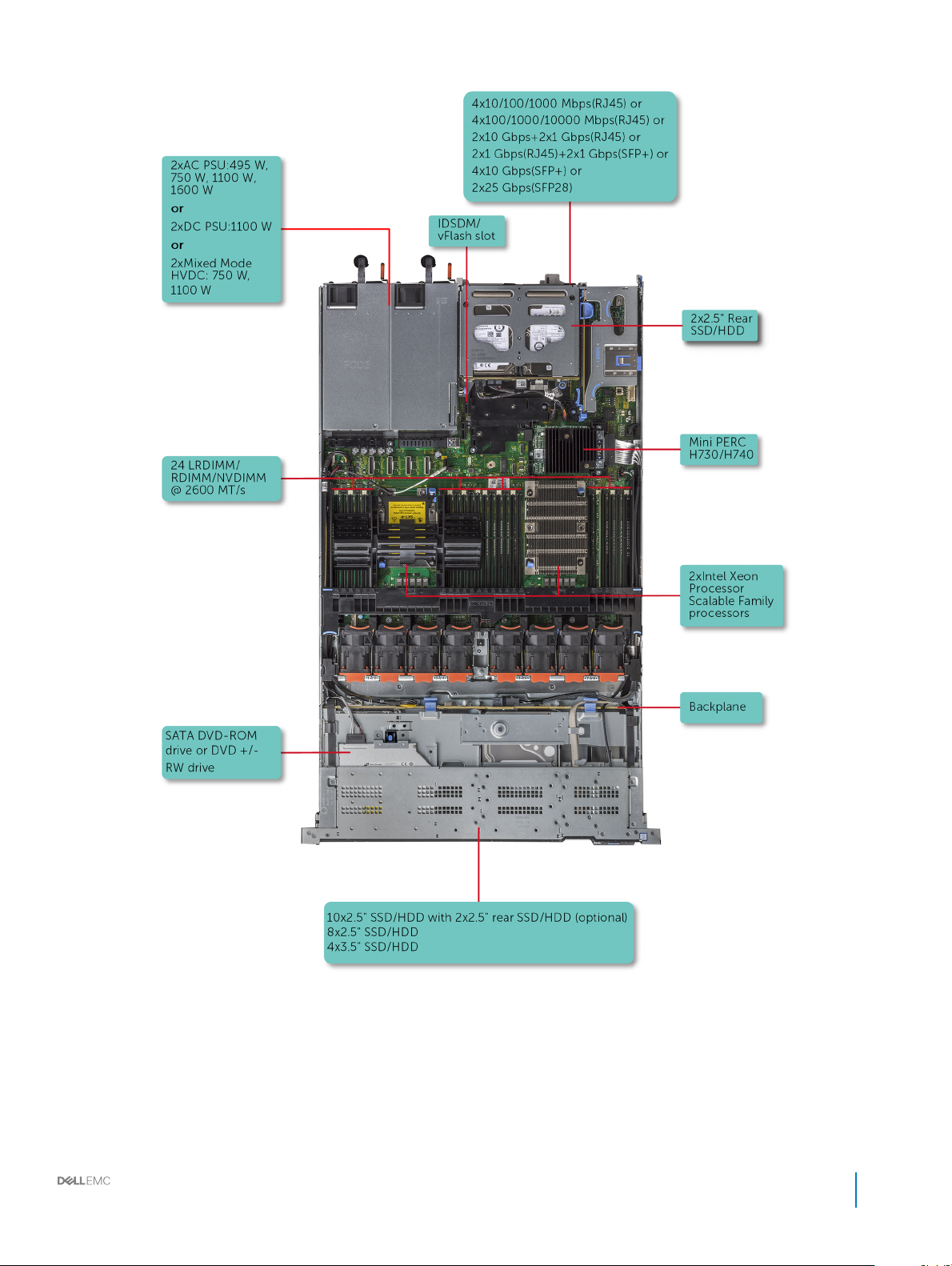
Figure 1. Supported congurations for PowerEdge R640
Dell EMC PowerEdge R640 Installation and Service Manual
PowerEdge R640 system overview
9
Page 10
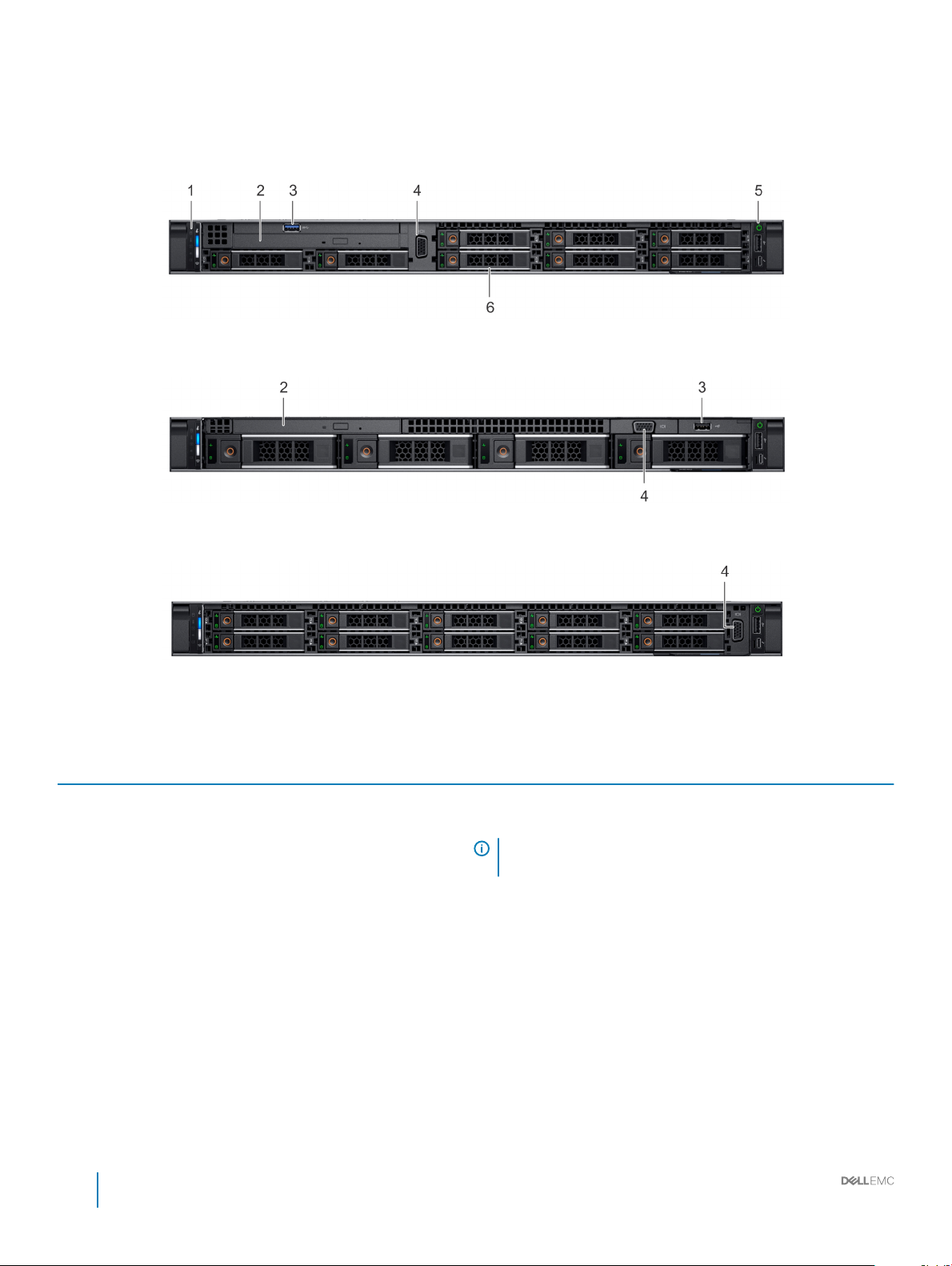
Front view of the system
The front view displays the features available on the front of the system.
Figure 2. Front view of 8 x 2.5 inch hard drive system
Figure 3. Front view of 4 x 3.5 inch hard drive system
Figure 4. Front view of 10 x 2.5 inch hard drive system
Table 1. Features available on the front of the system
Item Ports, panels, and slots Icon Description
1 Left control panel N/A
2 Optical drive (optional) N/A One optional slim SATA DVD-ROM drive or DVD+/-RW drive.
Contains the system health and system ID, status LED, and the
iDRAC Quick Sync 2 (wireless) indicator.
NOTE: The iDRAC Quick Sync 2 indicator is available only on
certain congurations.
• Status LED: Enables you to identify any failed hardware
components. There are up to ve status LEDs and an overall
system health LED (Chassis health and system ID) bar. For more
information, see the Status LED indicators section.
• Quick Sync 2 (wireless): Indicates a Quick Sync enabled system.
The Quick Sync feature is optional. This feature allows
management of the system by using mobile devices. This feature
aggregates hardware or rmware inventory and various system
level diagnostic and error information that can be used in
troubleshooting the system. For more information, see the
Integrated Dell Remote Access Controller User’s Guide at
Dell.com/idracmanuals.
10 Dell EMC PowerEdge R640 Installation and Service Manual
PowerEdge R640 system overview
Page 11
Item Ports, panels, and slots Icon Description
NOTE: DVD devices are data only.
3 USB port (optional)
4 VGA port
5 Right control panel N/A Contains the power button, USB port, iDRAC Direct micro port, and
6 Hard drive slots N/A
The USB port is USB 3.0 compliant.
Enables you to connect a display device to the system. For more
information, see the Technical specications section.
the iDRAC Direct status LED.
Enable you to install hard drives that are supported on your system.
For more information about hard drives, see the Technical
specications section.
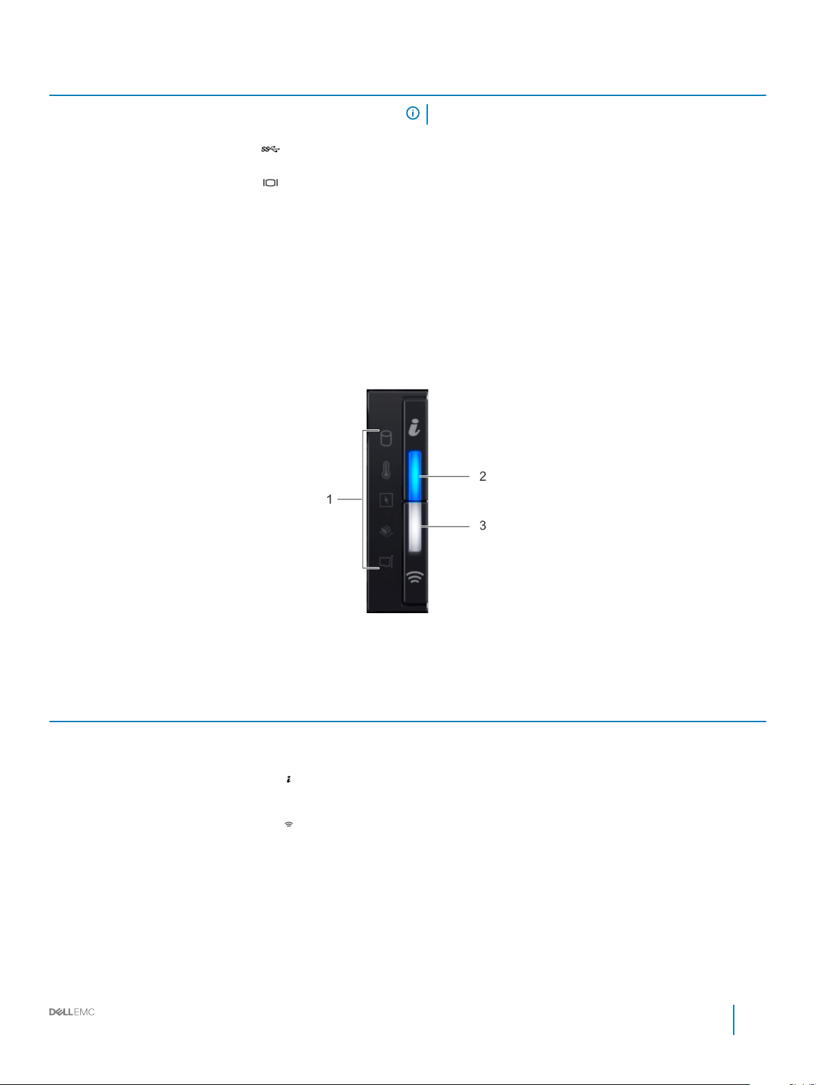
Left control panel view
Figure 5. Left control panel with optional iDRAC Quick Sync 2.0 indicator
Table 2. Left control panel
Item Indicator or button Icon Description
1 Status LED indicators N/A
2 System health and system
ID indicator
3 iDRAC Quick Sync 2
wireless indicator (optional)
Indicate the status of the system. For more information, see the
Status LED indicators section.
Indicates the system health. For more information, see the System
health and system ID indicator codes section.
Indicates if the iDRAC Quick Sync 2 wireless option is activated. The
Quick Sync 2 feature allows management of the system using mobile
devices. This feature aggregates hardware/rmware inventory and
various system level diagnostic/error information that can be used in
troubleshooting the system. You can access system inventory, Dell
Lifecycle Controller logs or system logs, system health status, and
also congure iDRAC, BIOS, and networking parameters. You can also
launch the virtual Keyboard, Video, and Mouse (KVM) viewer and
virtual Kernel based Virtual Machine (KVM), on a supported mobile
device. For more information, see the Integrated Dell Remote Access
Controller User's Guide at Dell.com/idracmanuals.
Dell EMC PowerEdge R640 Installation and Service Manual
11
PowerEdge R640 system overview
Page 12

Status LED indicators
NOTE: The status LED indicators are always o and only turns on to a solid amber if any error
occurs.
Table 3. Status LED indicators and descriptions
Icon Description Condition Corrective action
Drive indicator The indicator turns solid amber if
there is a drive error.
Temperature
indicator
Electrical indicator The indicator turns solid amber if the
Memory indicator The indicator turns solid amber if a
The indicator turns solid amber if the
system experiences a thermal error
(for example, the ambient
temperature is out of range or there is
a fan failure).
system experiences an electrical error
(for example, voltage out of range, or
a failed power supply unit (PSU) or
voltage regulator).
memory error occurs.
• Check the System Event Log to determine if the drive
has an error.
• Run the appropriate Online Diagnostics test. Restart
the system and run embedded diagnostics (ePSA).
• If the drives are congured in a RAID array, restart the
system, and enter the host adapter conguration
utility program.
Ensure that none of the following conditions exist:
• A cooling fan has been removed or has failed.
• System cover, air shroud, memory module blank, or
back ller bracket is removed.
• Ambient temperature is too high.
• External airow is obstructed.
If the problem persists, see the Getting help section.
Check the System Event Log or system messages for the
specic issue. If it is due to a problem with the PSU,
check the LED on the PSU. Reseat the PSU. If the
problem persists, see the Getting help section.
Check the System Event Log or system messages for the
location of the failed memory. Reseat the memory
module. If the problem persists, see the Getting help
section.
PCIe indicator The indicator turns solid amber if a
PCIe card experiences an error.
12 Dell EMC PowerEdge R640 Installation and Service Manual
PowerEdge R640 system overview
Restart the system. Update any required drivers for the
PCIe card. Reinstall the card. If the problem persists, see
the Getting help section.
NOTE: For more information about the
supported PCIe cards, see the Expansion card
installation guidelines section.
Page 13

System health and system ID indicator codes
The system health and system ID indicator is located on the left control panel of your system.
Figure 6. System health and system ID indicators
Table 4. System health and system ID indicator codes
System health and system ID indicator code Condition
Solid blue Indicates that the system is turned on, system is healthy, and system
ID mode is not active. Press the system health and system ID button
to switch to system ID mode.
Blinking blue Indicates that the system ID mode is active. Press the system health
and system ID button to switch to system health mode.
Solid amber Indicates that the system is in fail-safe mode. If the problem persists,
see the Getting help section.
Blinking amber Indicates that the system is experiencing a fault. Check the System
Event Log or the LCD panel, if available on the bezel, for specic error
message. For more information about error messages, see the Dell
Event and Error Messages Reference Guide at Dell.com/
openmanagemanuals > OpenManage software.
iDRAC Quick Sync 2 indicator codes
iDRAC Quick Sync 2 module (optional) is located on the left control panel of your system.
Figure 7. iDRAC Quick Sync 2 indicators
Table 5. iDRAC Quick Sync 2 indicators and descriptions
iDRAC Quick Sync 2 indicator
code
O (default state) Indicates that the iDRAC Quick Sync 2
Solid white Indicates that iDRAC Quick Sync 2 is ready
Condition Corrective action
If the LED fails to turn on, reseat the left control panel
feature is turned o. Press the iDRAC Quick
Sync 2 button to turn on the iDRAC Quick
Sync 2 feature.
to communicate. Press the iDRAC Quick
Sync 2 button to turn o.
ex cable and check again. If the problem persists,
see the Getting help section.
If the LED fails to turn o, restart the system. If the
problem persists, see the Getting help section.
Dell EMC PowerEdge R640 Installation and Service Manual
PowerEdge R640 system overview
13
Page 14
iDRAC Quick Sync 2 indicator
code
Blinks white rapidly Indicates data transfer activity. If the indicator continues to blink indenitely, see the
Condition Corrective action
Getting help section.
Blinks white slowly Indicates that rmware update is in
progress.
Blinks white ve times rapidly and
then turns o
Solid amber Indicates that the system is in fail-safe
Blinking amber Indicates that the iDRAC Quick Sync 2
Indicates that the iDRAC Quick Sync 2
feature is disabled.
mode.
hardware is not responding properly.
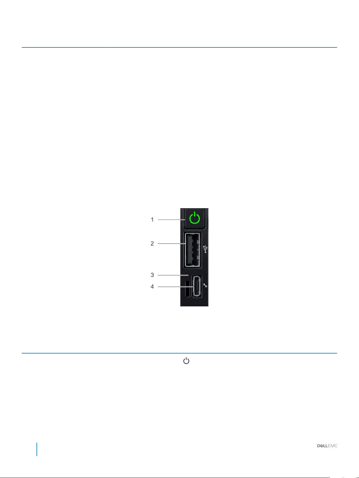
Right control panel view
If the indicator continues to blink indenitely, see the
Getting help section.
Check if iDRAC Quick Sync 2 feature is congured to
be disabled by iDRAC. If the problem persists, see the
Getting help section. For more information, see
Integrated Dell Remote Access Controller User's
Guide at Dell.com/idracmanuals or Dell
OpenManage Server Administrator User’s Guide at
Dell.com/openmanagemanuals.
Restart the system. If the problem persists, see the
Getting help section.
Restart the system. If the problem persists, see the
Getting help section.
Figure 8. Right control panel
Table 6. Right control panel
Item Indicator or button Icon Description
1 Power button
14 Dell EMC PowerEdge R640 Installation and Service Manual
PowerEdge R640 system overview
Indicates if the system is turned
on or o. Press the power
button to manually turn on or o
the system.
Page 15

Item Indicator or button Icon Description
NOTE: Press the power
button to gracefully shut
down an ACPI-compliant
operating system.
2 USB port
3 iDRAC Direct LED N/A The iDRAC Direct LED indicator
4 iDRAC Direct port
The USB ports are 4-pin, 2.0compliant. These ports enable
you to connect USB devices to
the system.
lights up to indicate that the
iDRAC Direct port is actively
connected to a device. For more
information, see the iDRAC
Direct LED indicator codes
section.
The iDRAC Direct port is micro
USB 2.0-compliant. This port
enables you to access the iDRAC
Direct features. For more
information, see the iDRAC
User’s Guide at Dell.com/
idracmanuals.
iDRAC Direct LED indicator codes
The iDRAC Direct LED indicator lights up to indicate that the port is connected and is being used as a part of the iDRAC subsystem.
You can congure iDRAC Direct by using a USB to micro USB (type AB) cable, which you can connect to your laptop or tablet. The
following table describes iDRAC Direct activity when the iDRAC Direct port is active:
Table 7. iDRAC Direct LED indicator codes
iDRAC Direct LED
indicator code
Solid green for two seconds Indicates that the laptop or tablet is connected.
Flashing green (on for two
seconds and o for two
seconds)
Turns o Indicates that the laptop or tablet is unplugged.
Condition
Indicates that the laptop or tablet connected is recognized.
Dell EMC PowerEdge R640 Installation and Service Manual
15
PowerEdge R640 system overview
Page 16
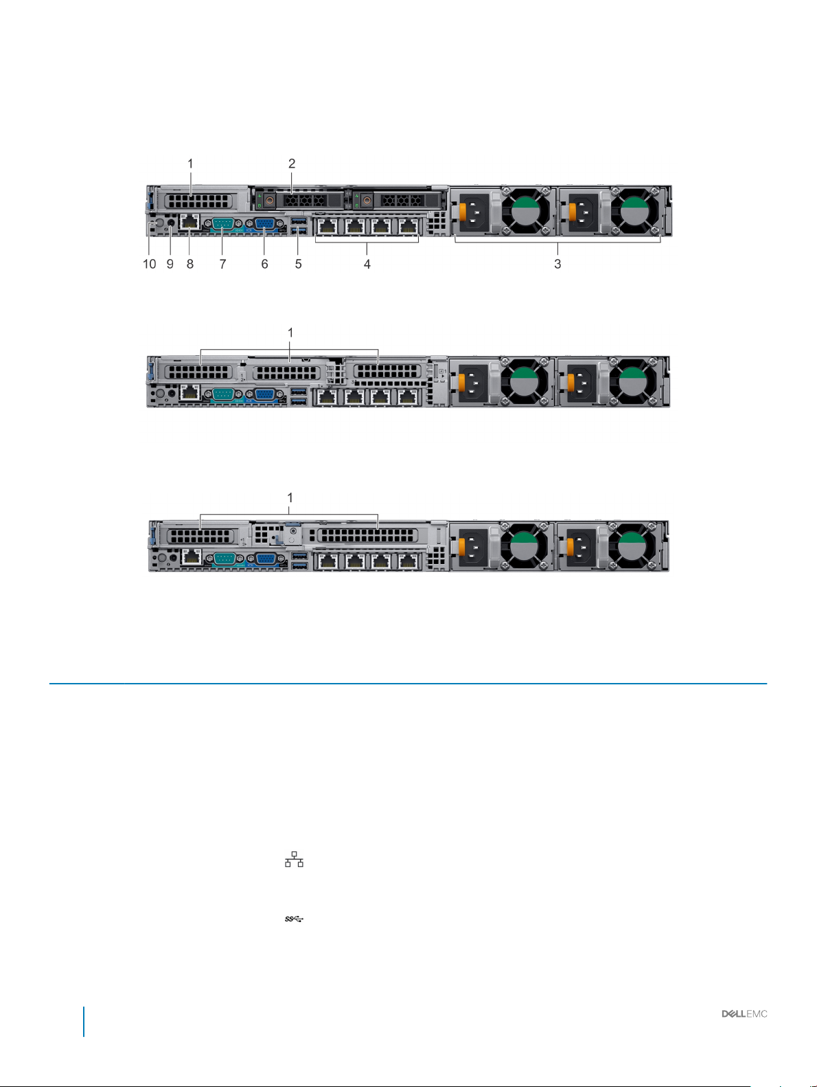
Back view of the system
The back view displays the features available on the back of the system.
Figure 9. Back view of 2 x 2.5 inch hard drives with 1 PCIe expansion slot
Figure 10. Back view of system with 3 PCIe expansion slots
Figure 11. Back view of system with 2 PCIe expansion slots
Table 8. 2 X 2.5 inch hard drive system with 1 PCIe expansion slot
Item Ports, panels, or slots Icon Description
1 PCIe expansion card slot(s) N/A
2 Hard drive slots N/A
3 Power supply unit (2) N/A For more information about the PSU congurations, see the Technical
4 NIC port (4)
5 USB 3.0 port
The expansion slot(s) enable you to connect PCI Express expansion
cards. For more information on the expansion cards that are supported
on your system, see the Expansion card guidelines.
Enable you to install hard drives that are supported on your system. For
more information about hard drives, see the Technical specications
section.
Specications section
The NIC ports that are integrated on the network daughter card (NDC)
provide network connectivity. For more information about the supported
congurations, see the Technical specications section.
The USB ports are 9-pin and 3.0-compliant. These ports enable you to
connect USB devices to the system.
16 Dell EMC PowerEdge R640 Installation and Service Manual
PowerEdge R640 system overview
Page 17
Item Ports, panels, or slots Icon Description
6 VGA port
Enables you to connect a display device to the system. For more
information, see the Technical specications section.
7 Serial port
8 iDRAC9 Enterprise port
9 CMA power port N/A The Cable Management Arm (CMA) power port enables you to connect
10 System identication button
Enables you to connect a serial device to the system. For more
information, see the Technical specications section.
Enables you to remotely access iDRAC. For more information, see the
iDRAC User’s Guide at Dell.com/idracmanuals.
to the CMA.
The System Identication (ID) button is available on the front and back of
the systems. Press the button to identify a system in a rack by turning on
the system ID button. You can also use the system ID button to reset
iDRAC and to access BIOS using the step through mode.
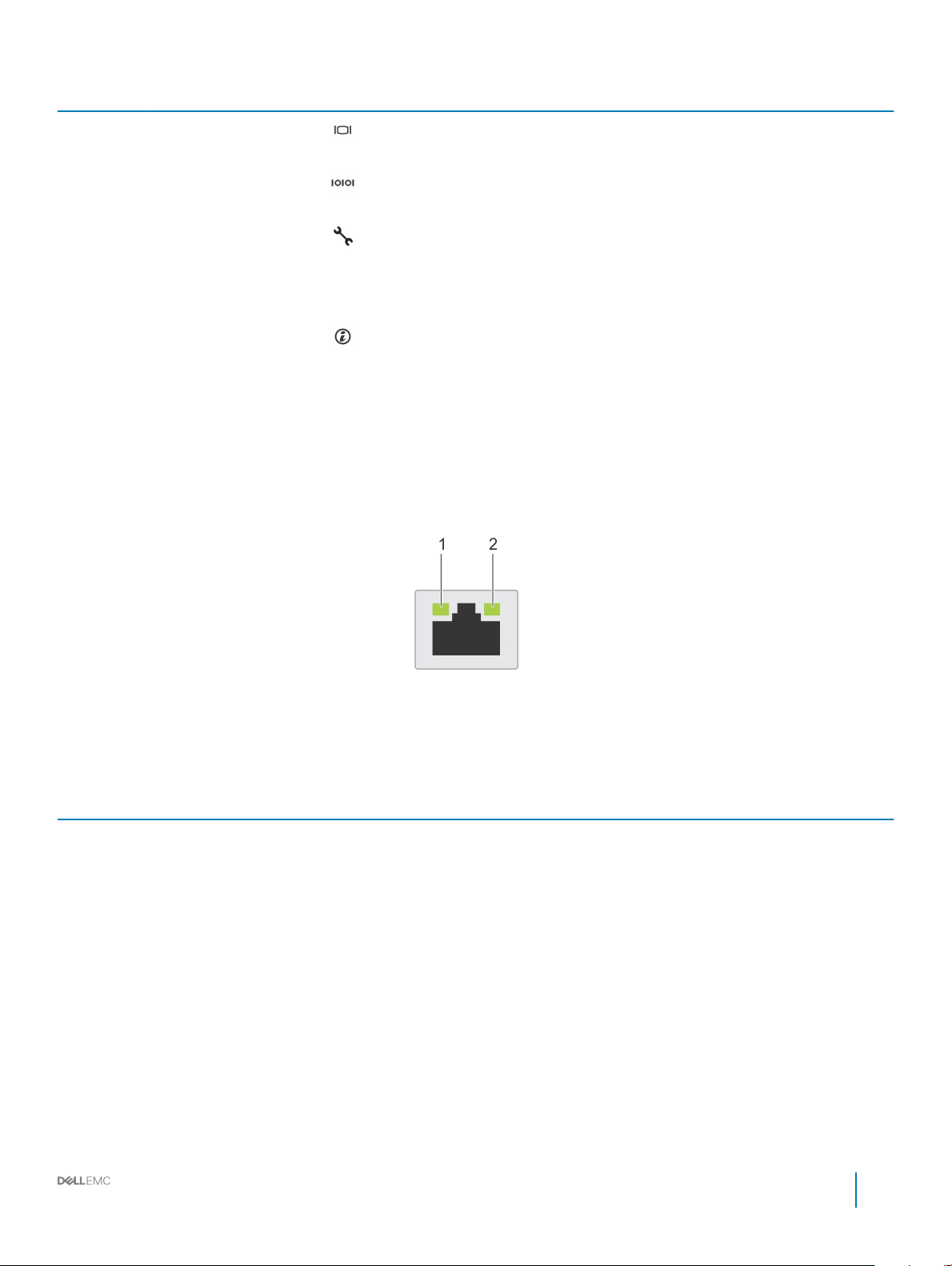
NIC indicator codes
Each NIC on the back panel has indicators that provide information about the activity and link status. The activity LED indicator indicates if
data is owing through the NIC, and the link LED indicator indicates the speed of the connected network.
Figure 12. NIC indicator codes
1
link LED indicator 2 activity LED indicator
Table 9. NIC indicator codes
Status Condition
Link and activity indicators are o The NIC is not connected to the network.
Link indicator is green and activity indicator is blinking green The NIC is connected to a valid network at its maximum port speed and
data is being sent or received.
Link indicator is amber and activity indicator is blinking
green
Link indicator is green and activity indicator is o The NIC is connected to a valid network at its maximum port speed and
Link indicator is amber and activity indicator is o The NIC is connected to a valid network at less than its maximum port
Link indicator is blinking green and activity is o NIC identify is enabled through the NIC conguration utility.
The NIC is connected to a valid network at less than its maximum port
speed and data is being sent or received.
data is not being sent or received.
speed and data is not being sent or received.
Dell EMC PowerEdge R640 Installation and Service Manual
PowerEdge R640 system overview
17
Page 18
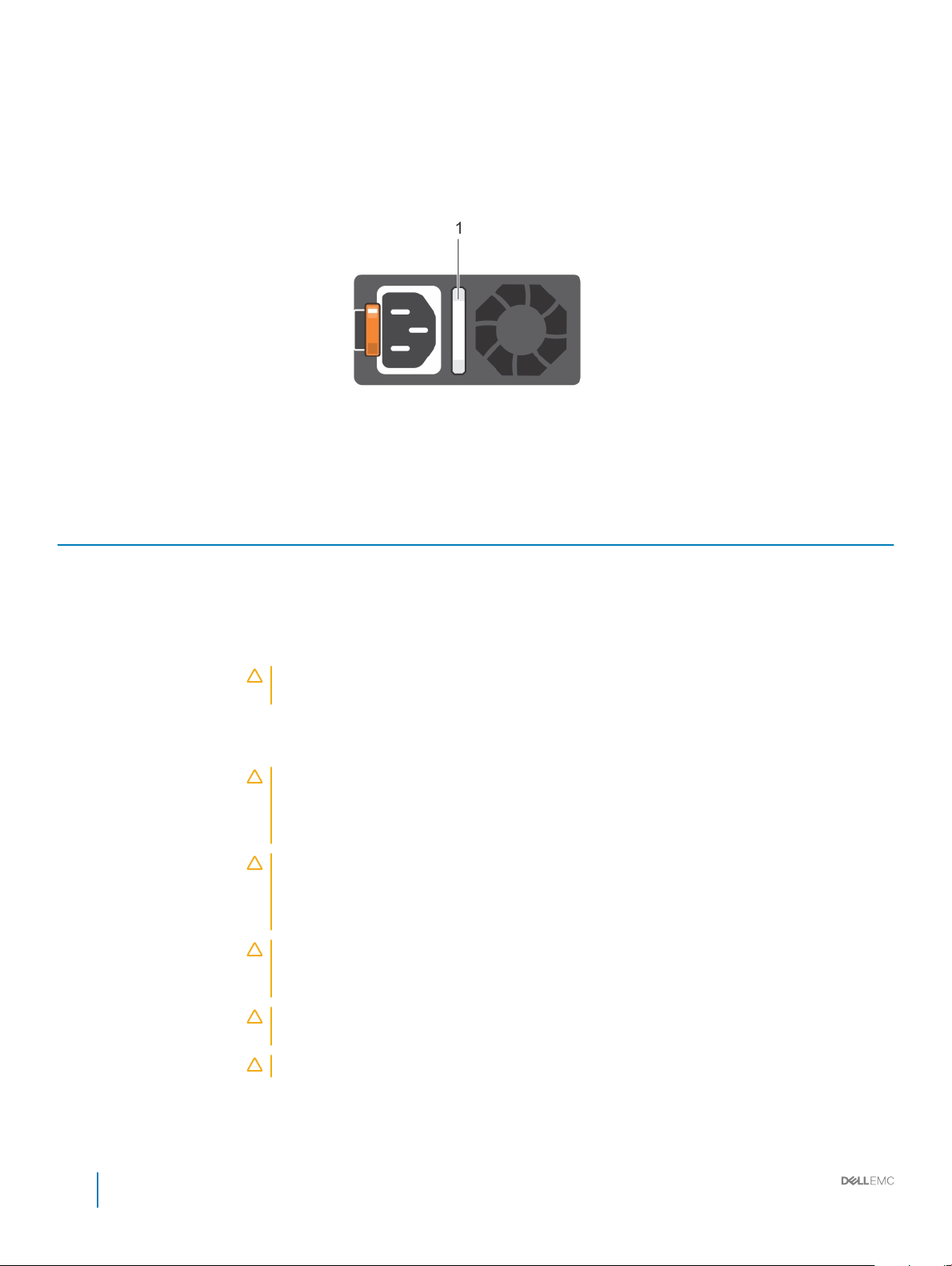
Power supply unit indicator codes
AC power supply units (PSUs) have an illuminated translucent handle that serves as an indicator and DC PSUs have an LED that serves as
an indicator. The indicator shows whether power is present or a power fault has occurred.
Figure 13. AC PSU status indicator
1 AC PSU status indicator/handle
Table 10. AC PSU status indicator codes
Power indicator codes Condition
Green A valid power source is connected to the PSU and the PSU is operational.
Blinking amber Indicates a problem with the PSU.
Not illuminated Power is not connected to the PSU.
Blinking green When the rmware of the PSU is being updated, the PSU handle blinks green.
CAUTION: Do not disconnect the power cord or unplug the PSU when updating rmware. If
rmware update is interrupted, the PSUs do not function.
Blinking green and turns o When hot-plugging a PSU, the PSU handle blinks green ve times at a rate of 4 Hz and turns o. This
indicates a PSU mismatch with respect to eciency, feature set, health status, or supported voltage.
CAUTION: If two PSUs are installed, both the PSUs must have the same type of label; for
example, Extended Power Performance (EPP) label. Mixing PSUs from previous generations of
PowerEdge servers is not supported, even if the PSUs have the same power rating. This results
in a PSU mismatch condition or failure to turn the system on.
CAUTION: When correcting a PSU mismatch, replace only the PSU with the blinking indicator.
Swapping the PSU to make a matched pair can result in an error condition and unexpected
system shutdown. To change from a high output conguration to a low output conguration or
vice versa, you must turn o the system.
CAUTION: AC PSUs support both 240 V and 120 V input voltages with the exception of Titanium
PSUs, which support only 240 V. When two identical PSUs receive dierent input voltages, they
can output dierent wattages, and trigger a mismatch.
CAUTION: If two PSUs are used, they must be of the same type and have the same maximum
output power.
CAUTION: Combining AC and DC PSUs is not supported and triggers a mismatch.
18 Dell EMC PowerEdge R640 Installation and Service Manual
PowerEdge R640 system overview
Page 19
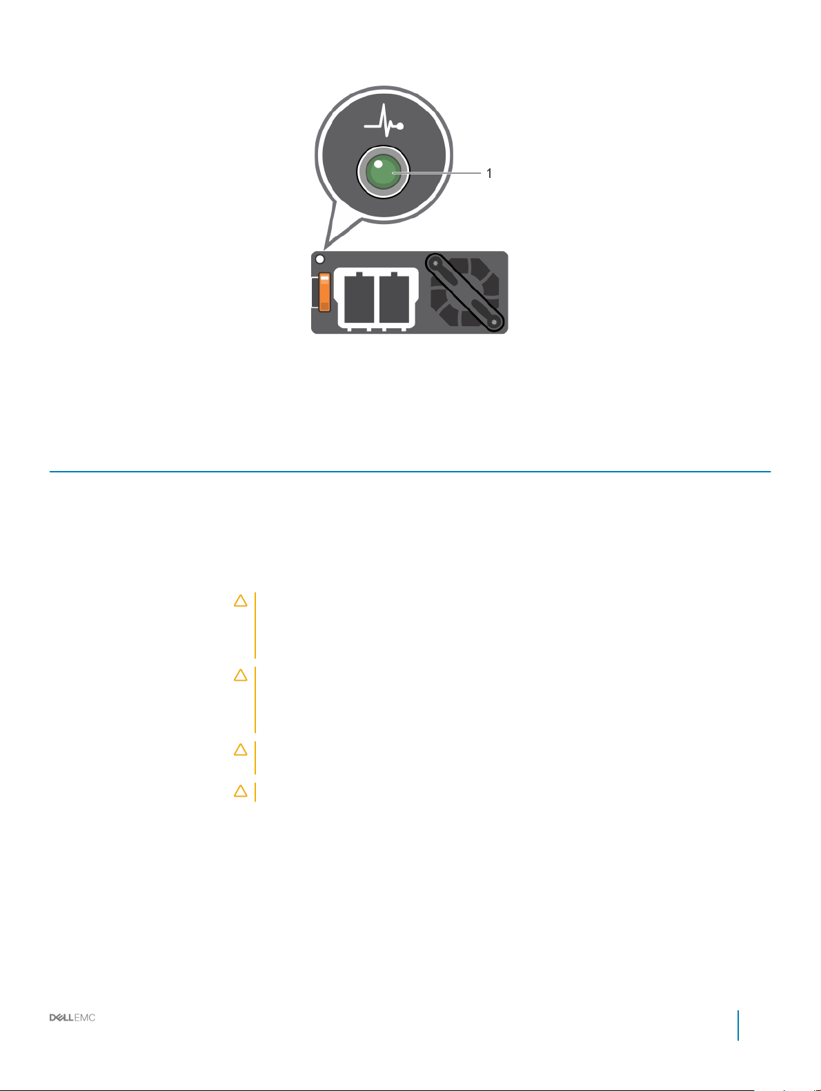
Figure 14. DC PSU status indicator
1 DC PSU status indicator
Table 11. DC PSU status indicator codes
Power indicator codes Condition
Green A valid power source is connected to the PSU and the PSU is operational.
Blinking amber Indicates a problem with the PSU.
Not illuminated Power is not connected to the PSU.
Blinking green When hot-plugging a PSU, the PSU indicator blinks green. This indicates that there is a PSU mismatch
with respect to eciency, feature set, health status, or supported voltage.
CAUTION: If two PSUs are installed, both the PSUs must have the same type of label; for
example, Extended Power Performance (EPP) label. Mixing PSUs from previous generations
of PowerEdge servers is not supported, even if the PSUs have the same power rating. This
results in a PSU mismatch condition or failure to turn the system on.
CAUTION: When correcting a PSU mismatch, replace only the PSU with the blinking
indicator. Swapping the PSU to make a matched pair can result in an error condition and
unexpected system shutdown. To change from a High Output conguration to a Low Output
conguration or vice versa, you must turn o the system.
CAUTION: If two PSUs are used, they must be of the same type and have the same
maximum output power.
CAUTION: Combining AC and DC PSUs is not supported and triggers a mismatch.
Dell EMC PowerEdge R640 Installation and Service Manual
PowerEdge R640 system overview
19
Page 20
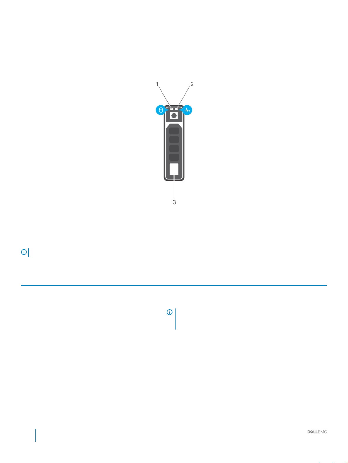
Hard drive indicator codes
Each hard drive carrier has an activity LED indicator and a status LED indicator. The indicators provide information about the current status
of the hard drive. The activity LED indicator indicates whether the hard drive is currently in use or not. The status LED indicator indicates
the power condition of the drive.
Figure 15. Hard drive indicators
1
hard drive activity LED indicator 2 hard drive status LED indicator
3 hard drive
NOTE: If the hard drive is in the Advanced Host Controller Interface (AHCI) mode, the status LED indicator does not turn on.
Table 12. Hard drive indicator codes
Hard drive status indicator code Condition
Flashes green twice per second Identifying drive or preparing for removal.
O Drive ready for removal.
NOTE: The drive status indicator remains o until all drives are
initialized after the system is turned on. Drives are not ready
for removal during this time.
Flashes green, amber, and then turns o Predicted drive failure.
Flashes amber four times per second Drive failed.
Flashes green slowly Drive rebuilding.
Solid green Drive online.
Flashes green for three seconds, amber for three seconds, and
then turns o after six seconds
Rebuild stopped.
20 Dell EMC PowerEdge R640 Installation and Service Manual
PowerEdge R640 system overview
Page 21
LCD panel
The LCD panel provides system information, status, and error messages to indicate if the system is functioning correctly or requires
attention. The LCD panel can be used to congure or view the system’s iDRAC IP address. For more information about error messages, see
the Dell Event and Error Messages Reference Guide at Dell.com/openmanagemanuals > OpenManage software.
The LCD panel is available only on the optional LCD bezel. The optional LCD bezel is hot pluggable.
The statuses and conditions of the LCD panel are outlined here:
• The LCD backlight is white during normal operating conditions.
• When the system needs attention, the LCD backlight turns amber, and displays an error code followed by descriptive text.
NOTE: If the system is connected to a power source and an error is detected, the LCD turns amber regardless of whether
the system is turned on or o.
• When the system turns o and there are no errors, LCD enters the standby mode after ve minutes of inactivity. Press any button on
the LCD to turn it on.
• If the LCD panel stops responding, remove the bezel and reinstall it. If the problem persists, see the Getting help section.
• The LCD backlight remains o if LCD messaging is turned o using the iDRAC utility, the LCD panel, or other tools.
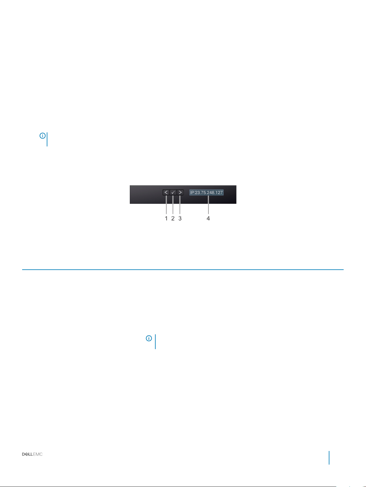
Figure 16. LCD panel features
Table 13. LCD panel features
Item Button or display Description
1 Left Moves the cursor back in one-step increments.
2 Select Selects the menu item highlighted by the cursor.
3 Right Moves the cursor forward in one-step increments.
During message scrolling:
• Press and hold the right button to increase scrolling speed.
• Release the button to stop.
NOTE: The display stops scrolling when the button is released. After 45
seconds of inactivity, the display starts scrolling.
4 LCD display Displays system information, status, and error messages or iDRAC IP address.
Viewing Home screen
The Home screen displays user-congurable information about the system. This screen is displayed during normal system operation when
there are no status messages or errors. When the system turns o and there are no errors, LCD enters the standby mode after ve
minutes of inactivity. Press any button on the LCD to turn it on.
1 To view the Home screen, press one of the three navigation buttons (Select, Left, or Right).
2 To navigate to the Home screen from another menu, complete the following steps:
Dell EMC PowerEdge R640 Installation and Service Manual
21
PowerEdge R640 system overview
Page 22

a Press and hold the navigation button till the up arrow is displayed.
b Navigate to the Home icon using the up arrow .
c Select the Home icon.
d On the Home screen, press the Select button to enter the main menu.
Setup menu
NOTE: When you select an option in the Setup menu, you must conrm the option before proceeding to the next
action.
Option Description
iDRAC Select DHCP or Static IP to congure the network mode. If Static IP is selected, the available elds are IP,
Subnet (Sub), and Gateway (Gtw). Select Setup DNS to enable DNS and to view domain addresses. Two
separate DNS entries are available.
Set error Select SEL to view LCD error messages in a format that matches the IPMI description in the SEL. This enables you
to match an LCD message with an SEL entry.
Select Simple to view LCD error messages in a simplied user-friendly description. For more information about
error messages, see the Dell Event and Error Messages Reference Guide at Dell.com/openmanagemanuals >
OpenManage software.
Set home Select the default information to be displayed on the Home screen. See View menu section for the options and
option items that can be set as the default on the Home screen.
View menu
NOTE
: When you select an option in the View menu, you must conrm the option before proceeding to the next
action.
Option Description
iDRAC IP Displays the IPv4 or IPv6 addresses for iDRAC9. Addresses include DNS (Primary and Secondary), Gateway, IP,
and Subnet (IPv6 does not have Subnet).
MAC Displays the MAC addresses for iDRAC, iSCSI, or Network devices.
Name Displays the name of the Host, Model, or User String for the system.
Number Displays the Asset tag or the Service tag for the system.
Power Displays the power output of the system in BTU/hr or Watts. The display format can be congured in the Set
home submenu of the Setup menu.
Temperature Displays the temperature of the system in Celsius or Fahrenheit. The display format can be congured in the Set
home submenu of the Setup menu.
Locating Service Tag of your system
You can identify your system using the unique Express Service Code and Service Tag. Pull out the information tag in front of the system to
view the Express Service Code and Service Tag. Alternatively, the information may be on a sticker on the chassis of the system. The mini
Enterprise Service Tag (EST) is found on the back of the system. This information is used by Dell to route support calls to the appropriate
personnel.
22
Dell EMC PowerEdge R640 Installation and Service Manual
PowerEdge R640 system overview
Page 23
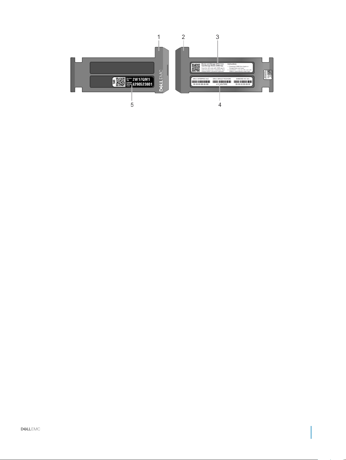
Figure 17. Locating Service Tag of your system
1 information tag (top view) 2 information tag (back view)
3 OpenManage Mobile (OMM) label 4 iDRAC MAC address and iDRAC secure password label
5 Service Tag
Dell EMC PowerEdge R640 Installation and Service Manual
PowerEdge R640 system overview
23
Page 24

Documentation resources
This section provides information about the documentation resources for your system.
Table 14. Additional documentation resources for your system
Task Document Location
Setting up your system
For more information about installing and securing
the system into a rack, see the rack documentation
included with your rack solution.
Dell.com/poweredgemanuals
2
For information about setting up and turning on the
system, see the Getting Started Guide document
that is shipped with your system.
Conguring your system For information about the iDRAC features,
conguring and logging in to iDRAC, and managing
your system remotely, see the Integrated Dell
Remote Access Controller User's Guide.
For information about installing the operating
system, see the operating system documentation.
For information about understanding Remote
Access Controller Admin (RACADM)
subcommands and supported RACADM interfaces,
see the RACADM Command Line Reference Guide
for iDRAC.
For information about updating drivers and
rmware, see the Methods to download rmware
and drivers section in this document.
Managing your system For information about systems management
software oered by Dell, see the Dell OpenManage
Systems Management Overview Guide.
For information about setting up, using, and
troubleshooting OpenManage, see the Dell
OpenManage Server Administrator User’s Guide.
Dell.com/poweredgemanuals
Dell.com/idracmanuals
Dell.com/operatingsystemmanuals
Dell.com/idracmanuals
To download drivers: Dell.com/support/drivers
Dell.com/openmanagemanuals
Dell.com/openmanagemanuals
For information about installing, using, and
troubleshooting Dell OpenManage Essentials, see
the Dell OpenManage Essentials User’s Guide.
For information about installing and using Dell
SupportAssist, see the Dell EMC SupportAssist
Enterprise User’s Guide.
For understanding the features of Dell Lifecycle
Controller, see the Dell Lifecycle Controller User’s
Guide.
24 Dell EMC PowerEdge R640 Installation and Service Manual
Documentation resources
Dell.com/openmanagemanuals
Dell.com/serviceabilitytools
Dell.com/idracmanuals
Page 25

Task Document Location
For information about partner programs enterprise
systems management, see the OpenManage
Connections Enterprise Systems Management
documents.
Working with the Dell
PowerEdge RAID controllers
Understanding event and error
messages
Troubleshooting your system For information about identifying and
For information about understanding the features
of the Dell PowerEdge RAID controllers (PERC),
Software RAID controllers, or BOSS card and
deploying the cards, see the Storage controller
documentation.
For information about checking the event and error
messages generated by the system rmware and
agents that monitor system components, see the
Dell Event and Error Messages Reference Guide.
troubleshooting the PowerEdge server issues, see
the Server Troubleshooting Guide.
Dell.com/openmanagemanuals
Dell.com/storagecontrollermanuals
Dell.com/openmanagemanuals > OpenManage
software
Dell.com/poweredgemanuals
Dell EMC PowerEdge R640 Installation and Service Manual
Documentation resources
25
Page 26

Technical specications
The technical and environmental specications of your system are outlined in this section.
Topics:
• System dimensions
• Chassis weight
• Processor specications
• PSU specications
• System battery specications
• Expansion bus specications
• Memory specications
• Storage controller specications
• Hard drive specications
• Ports and connectors specications
• Environmental specications
3
26 Dell EMC PowerEdge R640 Installation and Service Manual
Technical specications
Page 27
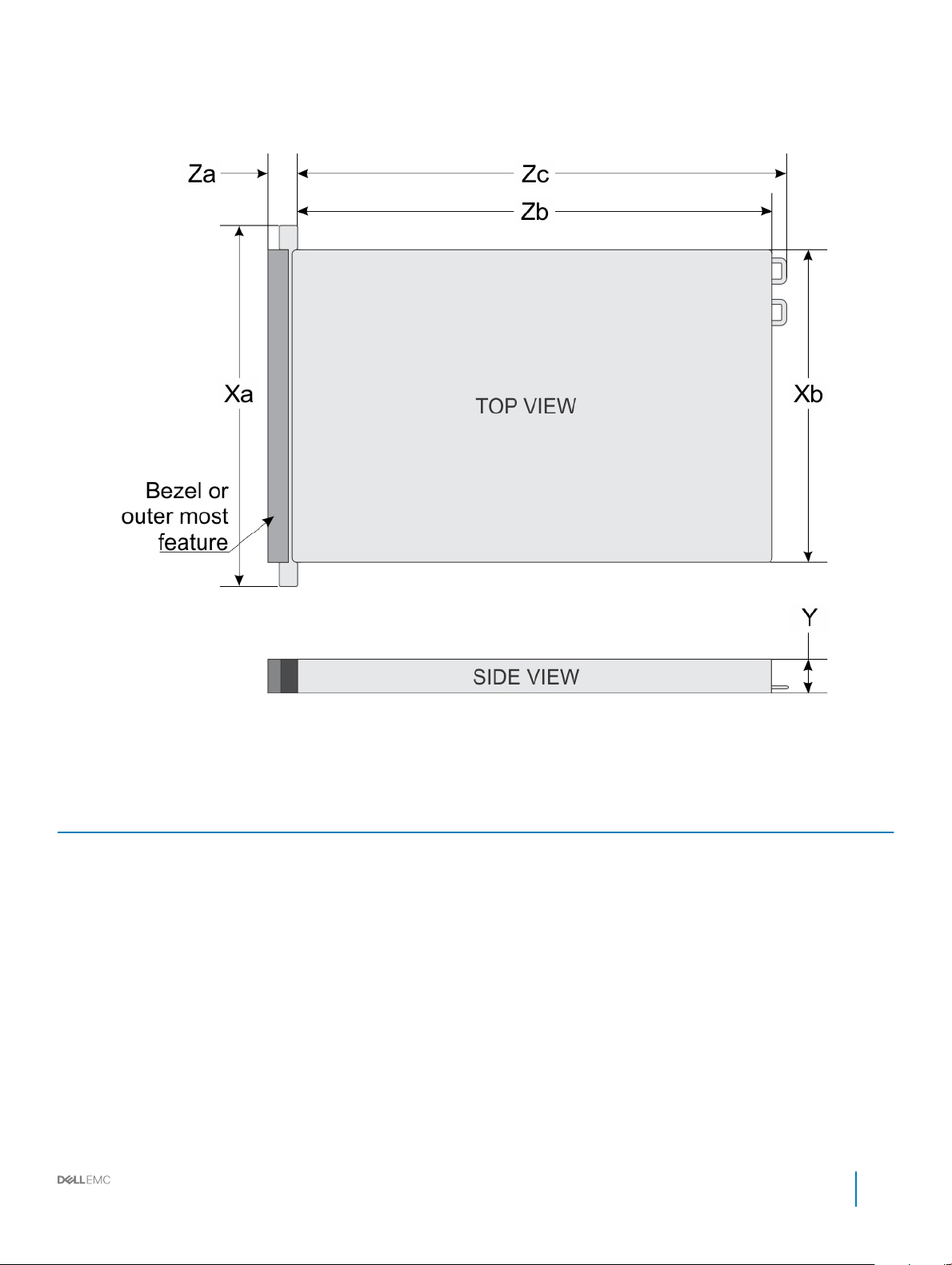
System dimensions
Figure 18. System dimensions
Table 15. Dimensions
System Xa Xb Y Za (with
4 x 3.5 inch
or
10 x 2.5 inches
8 x 2.5 inch 482.0 mm
482.0 mm
(18.97
inches)
(18.97
inches)
434.0 mm
(17.08 inches)
434.0 mm
(17.08 inches)
42.8 mm
(1.68 inches)
42.8 mm
(1.68 inches)
bezel)
35.84 mm
(1.41 inches)
35.84 mm
(1.41 inches)
Dell EMC PowerEdge R640 Installation and Service Manual
Za (without
bezel)
22.0 mm
(0.87 inches)
22.0 mm
(0.87 inches)
*
Zb
733.82 mm
(29.61 inches)
683.05 mm
(26.89 inches)
Technical specications
Zc
772.67
mm
(30.42
inches)
721.91
(28.42
inches)
27
Page 28

Chassis weight
Table 16. Chassis weight
System Maximum weight (with all hard drives/SSDs)
PowerEdge R640 21.9 kg
(48.28 lbs)
Processor specications
The PowerEdge R640 system supports two Intel Xeon Processor Scalable Family processors.
PSU specications
The PowerEdge R640 system supports up to two AC or DC power supply units (PSUs).
Table 17. PSU specications
PSU Class Heat dissipation
495 W AC Platinum 1908 BTU/hr 50/60 Hz 100–240 V AC, autoranging
750 W AC Platinum 2891 BTU/hr 50/60 Hz 100–240 V AC, autoranging
750 W AC Titanium 2843 BTU/hr 50/60 Hz 200–240 V AC, autoranging
750 W Mixed Mode
HVDC (for China
only)
1100 W DC Gold 4416 BTU/hr 50/60 Hz –(48–60) V DC
1100 W Mixed Mode
HVDC (for China
and Japan only)
1100 W AC Platinum 4100 BTU/hr 50/60 Hz 100–240 V AC, autoranging
1600 W AC 6000 BTU/hr 50/60 Hz 100–240 V AC, autoranging
NOTE: If a system with 1100 W AC or HVDC PSU operates from 100 to 120V, the power rating per PSU is derated to 1050 W.
NOTE: If a system with 1600 W PSUs operates from 100 to 120 V, then the power rating per PSU is derated to 800 W.
NOTE: Heat dissipation is calculated using the PSU wattage rating.
NOTE: This system is also designed to connect to the IT power systems with a phase to phase voltage not exceeding 230 V.
Platinum 4100 BTU/hr 50/60 Hz 100–240 V AC and 200–380 V DC
(maximum)
2891 BTU/hr 50/60 Hz 100–240 V AC and 240 V DC
Frequency Voltage
System battery specications
The PowerEdge R640 system supports CR 2032 lithium coin cell system battery.
28
Dell EMC PowerEdge R640 Installation and Service Manual
Technical specications
Page 29

Expansion bus specications
The PowerEdge R640 system supports PCI express (PCIe) generation 3 expansion cards, which are installed on the system, using
expansion card risers. This system supports 1A, 2A, 1B, and 2B expansion card risers.
Memory specications
Table 18. Memory specications
Memory module
sockets
Twenty four 288pins
NOTE: 8 GB RDIMMs and NVDIMM-N must not be mixed.
NOTE: Minimum of two CPUs are required for any conguration that supports NVDIMM-
N.
Architecture Memory capacity Minimum RAM Maximum RAM
2667 MT/s DDR4 RDIMMs and
LRDIMMs with support for
memory optimized operation
64 GB quad rank
(LRDIMMs)
8 GB single rank
(RDIMMs)
16 GB or 32 GB dual rank
(RDIMMs)
16 GB (NVDIMM-N)
208 GB with dual
processors
32 GB (minimum
LRDIMM size) with
single processor
8 GB with dual
processors (minimum
one memory module per
processor)
Not supported with
single processor
576 GB with dual
processors
LRDIMM: up to 786 GB
with single processor
LRDIMM: up to 1536 GB
with dual processors
RDIMM: up to 384 GB
with single processor
RDIMM: up to 786 GB
with dual processors
Not supported with
single processor
Storage controller specications
The PowerEdge R640 system supports:
• Internal storage controller cards: PowerEdge RAID Controller (PERC) H330, PERC H730P, PERC H740P, HBA330, S140, and Boot
Optimized Server Storage (BOSS-S1).
• External storage controller cards: PERC H840 and 12Gbps SAS HBA.
Hard drive specications
The PowerEdge R640 supports SAS, SATA, Nearline SAS hard drives or solid state drives and an optional optical drive.
Hard drives
The PowerEdge R640 system supports SAS, SATA, Nearline SAS hard drives or SSDs.
Dell EMC PowerEdge R640 Installation and Service Manual
Technical specications
29
Page 30

Table 19. Supported hard drive options for the PowerEdge R640 system
Ten drive systems with two rear hard drives Up to ten 2.5 inch, hot swappable SAS, SATA, SAS/SATA SSD, or Nearline SAS hard
drives with up to 2 x 2.5 inch hot swappable SAS, SATA, SAS/SATA SSD, or Nearline
SAS hard drives supported at the back of the system.
Eight drive systems Up to eight 2.5 inch, hot swappable SAS, SATA, SAS/SATA SSD, or Nearline SAS
hard drives
Four drive systems with two rear drives Up to four 3.5 inch, hot swappable hard drives with up to 2 x 2.5 inch hot swappable
SAS, SATA, SAS/SATA SSD, or Nearline SAS hard drives supported at the back of
the system.
Optical drive
Certain congurations of the system support one optional SATA DVD-ROM drive or DVD+/-RW drive.
NOTE: The optical drive is supported in both 4 x 3.5 and 8 x 2.5 inch hard drive systems.
Ports and connectors specications
The PowerEdge R640 supports USB ports, NIC ports, VGA ports, serial connector, and an IDSDM/vFlash card that supports an optional
ash memory card and one internal dual SD module.
USB ports
The PowerEdge R640 system supports:
• USB 2.0-compliant port on the front panel
• Micro USB 2.0-compliant port in the front panel
NOTE
: The micro USB 2.0-compliant port on the front panel can only be used as an iDRAC Direct or a management port.
• USB 3.0-compliant ports on the back panel
NOTE
: One optional USB 3.0-compliant port on the front panel for 4 x 3.5 and 8 x 2.5 inch hard drive systems.
• Internal USB 3.0-compliant port
The following table provides more information about the USB specications:
Table 20. USB
System Front panel Back panel Internal
Four hard drive systems One 4-pin, USB 2.0-compliant
Eight hard drive systems One 4-pin, USB 2.0-compliant
specications
ports
One 5-pin micro USB 2.0
management port
ports
Two 9-pin, USB 3.0-compliant
ports
N/A N/A
Two 9-pin, USB 3.0-compliant
ports
N/A
N/A
One 5-pin micro USB 2.0
management port
30 Dell EMC PowerEdge R640 Installation and Service Manual
Technical specications
N/A N/A
Page 31

System Front panel Back panel Internal
Ten hard drive systems One 4-pins, USB 2.0-compliant
port
One 5-pin micro USB 2.0
management port
Two 9-pin, USB 3.0-compliant
ports
N/A N/A
One 9-pin, USB 3.0-compliant
ports
NIC ports
The PowerEdge R640 system supports four Network Interface Controller (NIC) ports on the back panel, which are available in the
following congurations:
• Four RJ-45 ports that support 10, 100 and 1000 Mbps
• Four RJ-45 ports that support 100 M, 1 G and 10 Gbps
• Four RJ-45 ports, where two ports support maximum of 10 G and the other two ports maximum of 1 Gbps
• Two RJ-45 ports that support up to 1 Gbps and 2 SFP+ ports that support up to 10 Gbps
• Four SFP+ ports that support up to 10 Gbps
• Two SFP28 ports that support up to 25 Gbps
NOTE: You can install up to three PCIe add-on NIC cards.
Serial port
The PowerEdge R640 system supports one serial port on the back panel. This port is a 9-pin connector, Data Terminal Equipment (DTE),
16550-compliant.
VGA ports
The Video Graphic Array (VGA) port enables you to connect the system to a VGA display. The PowerEdge R640 system supports one 15pin VGA port on the front and back of system.
Video specications
The PowerEdge R640 system supports integrated VGA controller with 4 MB SPI capacity.
Table 21. Supported video resolution options
Resolution Refresh rate (Hz) Color depth (bits)
640 x 480 60, 70 8, 16, 32
800 x 600 60, 75, 85 8, 16, 32
1024 x 768 60, 75, 85 8, 16, 32
1152 x 864 60, 75, 85 8, 16, 32
1280 x 1024 60, 75 8, 16, 32
1440 x 900 60 8, 16, 32
1920 x 1200 60 8, 16, 32
Dell EMC PowerEdge R640 Installation and Service Manual
31
Technical specications
Page 32

IDSDM/vFlash card
The PowerEdge R640 system supports Internal Dual SD module (IDSDM) and vFlash card. In the 14th generation of PowerEdge servers,
IDSDM and vFlash card are combined into a single module, and are available in the following options:
• vFlash or
• vFlash and IDSDM
The IDSDM/vFlash card can be connected in a Dell-proprietary PCIe x1 slot using a USB 3.0 interface to host. IDSDM/vFlash module
supports two micro SD cards for IDSDM and one card for vFlash. Micro SD cards capacity for IDSDM are 16, 32, or 64 GB, while for vFlash
the microSD card capacity is 16 GB.
NOTE: One IDSDM card slot is dedicated for redundancy.
NOTE: It is recommended to use Dell branded micro SD cards associated with the IDSDM/vFlash congured
systems.
Environmental specications
NOTE: For additional information about environmental measurements for specic system congurations, see Dell.com/
environmental_datasheets.
Table 22. Temperature specications
Temperature Specications
Storage –40°C to 65°C (–40°F to 149°F)
Continuous operation (for altitude less than 950 m or 3117
ft)
Fresh air For information about fresh air, see Expanded Operating Temperature
Maximum temperature gradient (operating and storage) 20°C/h (68°F/h)
Table 23. Relative humidity specications
Relative humidity Specications
Storage 5% to 95% RH with 33°C (91°F) maximum dew point. Atmosphere must be
Operating 10% to 80% relative humidity with 29°C (84.2°F) maximum dew point.
10°C to 35°C (50°F to 95°F) with no direct sunlight on the equipment.
NOTE: Maximum of 205 W, 28 core processor is supported in
systems with eight 2.5 inch processor direct attached PCIe SSD
drives, and three PCIe slot chassis.
NOTE: Certain congurations may have ambient temperature
restrictions. For more information see the Ambient temperature
limitations section.
section.
non-condensing at all times.
32 Dell EMC PowerEdge R640 Installation and Service Manual
Technical specications
Page 33

Table 24. Maximum vibration specications
Maximum vibration Specications
Operating 0.26 G
Storage 1.88 G
Table 25. Maximum shock specications
Maximum shock Specications
Operating Six consecutively executed shock pulses in the positive and negative x, y,
and z axes of 6 G for up to 11 ms.
Storage Six consecutively executed shock pulses in the positive and negative x, y,
and z axes (one pulse on each side of the system) of 71 G for up to 2 ms.
Table 26. Maximum altitude specications
Maximum altitude Specications
Operating
Storage 12,000 m (39,370 ft)
Table 27. Operating temperature de-rating specications
Operating temperature de-rating Specications
3048 m (10,000 ft)
at 5 Hz to 350 Hz (all operation orientations).
rms
at 10 Hz to 500 Hz for 15 min (all six sides tested).
rms
Up to 35°C (95°F) Maximum temperature is reduced by 1°C/300 m (1°F/547 ft) above 950 m
(3,117 ft).
35°C to 40°C (95°F to 104°F) Maximum temperature is reduced by 1°C/175 m (1°F/319 ft) above 950 m
(3,117 ft).
40°C to 45°C (104°F to 113°F) Maximum temperature is reduced by 1°C/125 m (1°F/228 ft) above 950 m
(3,117 ft).
Standard operating temperature
Table 28. Standard operating temperature
Standard operating temperature Specications
Continuous operation (for altitude less than 950 m or 3117
ft)
specications
10°C to 35°C (50°F to 95°F) with no direct sunlight on the equipment.
Dell EMC PowerEdge R640 Installation and Service Manual
Technical specications
33
Page 34

Expanded operating temperature
Table 29. Expanded operating temperature specications
Expanded operating temperature Specications
Continuous operation 5°C–40°C at 5% to 85% RH with 29°C dew point.
NOTE: Outside the standard operating temperature (10°C–35°C),
the system can operate continuously in temperatures as low as 5°C
and as high as 40°C.
For temperatures between 35°C–40°C, de-rate maximum allowable
temperature by 1°C per 175 m above 950 m (1°F per 319 ft).
≤ 1% of annual operating hours –5°C–45°C at 5% to 90% RH with 29°C dew point.
NOTE: Outside the standard operating temperature (10°C–35°C),
the system can operate down to –5°C or up to 45°C for a
maximum of 1% of its annual operating hours.
For temperatures between 40°C and 45°C, de-rate maximum allowable
temperature by 1°C per 125 m above 950 m (1°F per 228 ft).
NOTE: When operating in the expanded temperature range, system performance may be impacted.
NOTE: When operating in the expanded temperature range, ambient temperature warnings may be reported on the LCD panel
and in the System Event Log.
Expanded operating temperature restrictions
• Do not perform a cold startup below 5°C.
• The operating temperature specied is for a maximum altitude of 3050 m (10,000 ft).
• 150 W/8 C, 165 W/12 C and higher wattage processor(TDP>165 W) are not supported.
• Redundant power supply unit is required.
• Non-Dell qualied peripheral cards and/or peripheral cards greater than 25 W are not supported.
• PCIe SSD is not supported.
• 3DX Point DIMMs and NVDIMMs-N are not supported.
• Rear installed drives are not supported
• Tape backup unit is not supported.
34
Dell EMC PowerEdge R640 Installation and Service Manual
Technical specications
Page 35

Thermal restrictions
The following table lists the congurations required for ecient cooling.
Table 30. Thermal restrictions conguration
Conguration Number
PowerEdge
R640 (2.5 inch
hard drives x
10)
PowerEdge
R640 (2.5 inch
hard drives x 10
with NVMe
drives)
PowerEdge
R640
(2.5 inch hard
drives x 8)
(3.5 inch hard
drives x 4)
of
processo
rs
1 One 1U standard heat
2 Two 1U standard heat
2 Two 1U standard heat
1 One 1U standard heat
Heatsink Processor/
sink for CPU ≤ 165 W
One 1U 2-pipe heat sink
for CPU=200/205 W
and 150 W/165 W FO*
sink for CPU ≤ 165 W
Two 1U 2-pipe heat sink
for CPU=200/205 W
and 150 W/165 W FO*
sink for CPU ≤ 165 W
Two 1U 2-pipe heat sink
for CPU=200/205 W
and 150 W/165 W FO*
sink for CPU ≤ 165 W
One 1U 2-pipe heat sink
for CPU=150 W/165 W
FO*
One 1U 2-pipe heat sink
for CPU=200/205 W
DIMM blank
Not required Required for
Required Eight high performance
Not required Eight standard fans
Not required Required 22 blanks Eight high performance
No Required for
DIMM
blanks
processor 1
Required 22 blanks Eight high performance
processor 1
Maximum number of
DIMM blanks
11 blanks Five standard fans
11 blanks Five standard fans
Fan
fans
fans
fans
2 Two 1U standard heat
sink for CPU ≤ 165 W
Two 1U 2-pipe heat sink
for CPU=150 W/165 W
Two 1U 2-pipe heat sink
for CPU=200/205 W
NOTE: *165 W and 150 W FO includes Intel Xeon Gold 6146 and 6144 processors.
Yes Eight high performance
No Required 22 blanks Eight standard fans
Dell EMC PowerEdge R640 Installation and Service Manual
fans
Eight high performance
fans
35
Technical specications
Page 36

Ambient temperature limitations
The following table lists congurations that require ambient temperature less than 35°C.
NOTE: The ambient temperature limit must be adhered to ensure proper cooling and to avoid excess processor throttling, which
may impact system performance.
Table 31. Conguration based ambient temperature restrictions
System Front Backplane Processor Thermal
PowerEdge R640
10 x 2.5 inch SAS/
SATA hard drives
8 x 2.5 inch SAS/SATA
hard drives
4 x 3.5 inch SAS/SATA
hard drives
10 x 2.5 inch SAS/
SATA and NVMe
drives(4, 8, or 10)
Design Power
200 W, 205 W 2 pipe 1U high
165 W, 200 W, 205 W2 pipe 1U high
Processor Heat Sink Fan Type Ambient Restriction
performance
performance
High performance
fan
High performance
fan
30°C
30°C
Particulate and gaseous contamination specications
The following table denes the limitations that help avoid any equipment damage or failure from particulate and gaseous contamination. If
the levels of particulate or gaseous pollution exceed the specied limitations and result in equipment damage or failure, you may need to
rectify the environmental conditions. Remediation of environmental conditions is the responsibility of the customer.
Table 32. Particulate contamination
Particulate contamination Specications
specications
Air ltration Data center air ltration as dened by ISO Class 8 per ISO 14644-1 with a
95% upper condence limit.
NOTE: This condition applies to data center environments only. Air
ltration requirements do not apply to IT equipment designed to be
used outside a data center, in environments such as an oce or
factory oor.
NOTE: Air entering the data center must have the MERV11 or
MERV13 ltration.
Conductive dust Air must be free of conductive dust, zinc whiskers, or other conductive
particles.
NOTE: This condition applies to data center and non-data center
environments.
Corrosive dust
36 Dell EMC PowerEdge R640 Installation and Service Manual
Technical specications
• Air must be free of corrosive dust.
• Residual dust present in the air must have a deliquescent point less than
60% relative humidity.
Page 37

Particulate contamination Specications
NOTE: This condition applies to data center and non-data center
environments.
Table 33. Gaseous contamination specications
Gaseous contamination Specications
Copper coupon corrosion rate <300 Å/month per Class G1 as dened by ANSI/ISA71.04-1985.
Silver coupon corrosion rate <200 Å/month as dened by AHSRAE TC9.9.
NOTE: Maximum corrosive contaminant levels measured at ≤50% relative humidity.
Dell EMC PowerEdge R640 Installation and Service Manual
Technical specications
37
Page 38

Initial system setup and conguration
Setting up your system
Complete the following steps to set up your system:
1 Unpack the system.
2 Install the system into the rack. For more information about installing the system into the rack, see your Rail Installation Guide at
Dell.com/poweredgemanuals.
3 Connect the peripherals to the system.
4 Connect the system to its electrical outlet.
5 Turn the system on by pressing the power button or by using iDRAC.
6 Turn on the attached peripherals.
For more information about setting up your system, see your Getting Started Guide shipped with your system.
Related links
iDRAC conguration
Options to set up iDRAC IP address
4
iDRAC conguration
The Integrated Dell Remote Access Controller (iDRAC) is designed to make system administrators more productive and improve the overall
availability of Dell systems. iDRAC alerts administrators to system issues, helps them perform remote system management, and reduces the
need for physical access to the system.
Options to set up iDRAC IP address
You must congure the initial network settings based on your network infrastructure to enable the communication to and from iDRAC.
You must use the default iDRAC IP address 192.168.0.120 to congure the initial network settings, including setting up DHCP or a static IP
for iDRAC. You can set up the IP address by using one of the following interfaces:
Interfaces
iDRAC Settings
utility
Dell Deployment
Toolkit
Dell Lifecycle
Controller
CMC Web interface See Dell Chassis Management Controller Firmware User’s Guide at Dell.com/esmmanuals
Document/Section
See Dell Integrated Dell Remote Access Controller User's Guide at Dell.com/idracmanuals
See Dell Deployment Toolkit User’s Guide at Dell.com/openmanagemanuals
See Dell Lifecycle Controller User’s Guide at Dell.com/idracmanuals
Chassis or Server
LCD panel
38 Dell EMC PowerEdge R640 Installation and Service Manual
Initial system setup and conguration
See the LCD panel section
Page 39

Interfaces Document/Section
iDRAC Direct and
Quick Sync 2
(optional)
NOTE: To access iDRAC, ensure that you connect the Ethernet cable to the iDRAC direct port. You can also access iDRAC
through the shared LOM mode, if you have opted for a system that has the shared LOM mode enabled.
See Dell Integrated Dell Remote Access Controller User's Guide at Dell.com/idracmanuals
Log in to iDRAC
You can log in to iDRAC as:
• iDRAC user
• Microsoft Active Directory user
• Lightweight Directory Access Protocol (LDAP) user
If you have opted for secure default access to iDRAC, the iDRAC secure default password is available on the back of the system
Information tag. If you have not opted for secure default access to iDRAC, then the default user name and password are root and
calvin. You can also log in by using Single Sign-On or Smart Card.
NOTE: You must have the iDRAC credentials to log in to iDRAC.
NOTE: Ensure that you change the default user name and password after setting up the iDRAC IP address.
For more information about logging in to the iDRAC and iDRAC licenses, see the latest Integrated Dell Remote Access Controller User's
Guide at Dell.com/idracmanuals.
You can also access iDRAC by using RACADM. For more information, see the RACADM Command Line Interface Reference Guide at
Dell.com/idracmanuals.
Options to install the operating system
If the system is shipped without an operating system, install the supported operating system by using one of the following resources:
Table 34. Resources to install the operating system
Resources Location
Systems Management Tools and Documentation media Dell.com/operatingsystemmanuals
Lifecycle Controller Dell.com/idracmanuals
OpenManage Deployment Toolkit Dell.com/openmanagemanuals
Dell certied VMware ESXi Dell.com/virtualizationsolutions
Supported operating systems on PowerEdge systems Dell.com/ossupport
Installation and How-to videos for supported operating systems on
PowerEdge systems
Methods to download rmware and drivers
Supported Operating Systems for Dell PowerEdge Systems
You can download the rmware and drivers by using any of the following methods:
Dell EMC PowerEdge R640 Installation and Service Manual
39
Initial system setup and conguration
Page 40

Table 35. Firmware and drivers
Methods Location
From the Dell Support site Dell.com/support/home
Using Dell Remote Access Controller Lifecycle Controller (iDRAC
with LC)
Using Dell Repository Manager (DRM) Dell.com/openmanagemanuals
Using Dell OpenManage Essentials (OME) Dell.com/openmanagemanuals
Using Dell Server Update Utility (SUU) Dell.com/openmanagemanuals
Using Dell OpenManage Deployment Toolkit (DTK) Dell.com/openmanagemanuals
Dell.com/idracmanuals
Downloading drivers and rmware
Dell recommends that you download and install the latest BIOS, drivers, and systems management rmware on your system.
Prerequisites
Ensure that you clear the web browser cache before downloading the drivers and rmware.
Steps
1 Go to Dell.com/support/drivers.
2 In the Drivers & Downloads section, type the Service Tag of your system in the Enter a Service Tag or product ID box, and then click
Submit.
NOTE
: If you do not have the Service Tag, select Detect Product to allow the system to automatically detect your
Service Tag, or click View products, and navigate to your product.
3 Click Drivers & Downloads.
The drivers that are applicable to your selection are displayed.
4 Download the drivers to a USB drive, CD, or DVD.
40
Dell EMC PowerEdge R640 Installation and Service Manual
Initial system setup and conguration
Page 41

Pre-operating system management applications
You can manage basic settings and features of a system without booting to the operating system by using the system rmware.
Topics:
• Options to manage the pre-operating system applications
• System Setup
• Dell Lifecycle Controller
• Boot Manager
• PXE boot
Options to manage the pre-operating system applications
Your system has the following options to manage the pre-operating system applications:
5
• System Setup
• Dell Lifecycle Controller
• Boot Manager
• Preboot Execution Environment (PXE)
Related links
System Setup
Dell Lifecycle Controller
Boot Manager
PXE boot
System Setup
By using the System Setup screen, you can congure the BIOS settings, iDRAC settings, and device settings of your system.
: Help text for the selected eld is displayed in the graphical browser by default. To view the help text in the text browser,
NOTE
press F1.
You can access system setup by using two methods:
• Standard graphical browser—The browser is enabled by default.
• Text browser—The browser is enabled by using Console Redirection.
Related links
System Setup details
Viewing System Setup
Dell EMC PowerEdge R640 Installation and Service Manual
Pre-operating system management applications
41
Page 42

Viewing System Setup
To view the System Setup screen, perform the following steps:
1 Turn on, or restart your system.
2 Press F2 immediately after you see the following message:
F2 = System Setup
NOTE: If your operating system begins to load before you press F2, wait for the system to nish booting, and then
restart your system and try again.
Related links
System Setup
System Setup details
System Setup details
The System Setup Main Menu screen details are explained as follows:
Option Description
System BIOS Enables you to congure BIOS settings.
iDRAC Settings Enables you to congure the iDRAC settings.
The iDRAC settings utility is an interface to set up and congure the iDRAC parameters by using UEFI (Unied
Extensible Firmware Interface). You can enable or disable various iDRAC parameters by using the iDRAC settings
utility. For more information about this utility, see Integrated Dell Remote Access Controller User’s Guide at
Dell.com/idracmanuals.
Device Settings Enables you to congure device settings.
Related links
System Setup
iDRAC Settings utility
Device Settings
Viewing System Setup
42
Dell EMC PowerEdge R640 Installation and Service Manual
Pre-operating system management applications
Page 43

System BIOS
You can use the System BIOS screen to edit specic functions such as boot order, system password, setup password, set the SATA and
PCIe NVMe RAID mode, and enable or disable USB ports.
Related links
System BIOS Settings details
Boot Settings
Network Settings
System Information
Memory Settings
Processor Settings
SATA Settings
Integrated Devices
Serial Communication
System Prole Settings
Miscellaneous Settings
iDRAC Settings utility
Device Settings
System Security
Viewing System BIOS
Viewing System BIOS
To view the System BIOS screen, perform the following steps:
1 Turn on, or restart your system.
2 Press F2 immediately after you see the following message:
F2 = System Setup
NOTE
: If your operating system begins to load before you press F2, wait for the system to nish booting, and then
restart your system and try again.
3 On the System Setup Main Menu screen, click System BIOS.
System BIOS Settings details
The System BIOS Settings screen details are explained as follows:
Option
System Information Species information about the system such as the system model name, BIOS version, and Service Tag.
Memory Settings Species information and options related to the installed memory.
Processor Settings Species information and options related to the processor such as speed and cache size.
SATA Settings Species options to enable or disable the integrated SATA controller and ports.
NVMe Settings Species options to change the NVMe settings. If the system contains the NVMe drives that you want to
Boot Settings Species options to specify the Boot mode (BIOS or UEFI). Enables you to modify UEFI and BIOS boot settings.
Description
congure in a RAID array, you must set both this eld and the Embedded SATA eld on the SATA Settings menu
to RAID mode. You might also need to change the Boot Mode setting to UEFI. Otherwise, you should set this eld
to Non-RAID mode.
Dell EMC PowerEdge R640 Installation and Service Manual
Pre-operating system management applications
43
Page 44

Option Description
Network Settings Species options to manage the UEFI network settings and boot protocols.
Legacy network settings are managed from the Device Settings menu.
Integrated Devices Species options to manage integrated device controllers and ports, species related features and options.
Serial
Communication
System Prole
Settings
System Security Species options to congure the system security settings, such as system password, setup password, Trusted
Redundant OS
Settings
Miscellaneous
Settings
Species options to manage the serial ports, its related features and options.
Species options to change the processor power management settings, memory frequency.
Platform Module (TPM) security, and UEFI secure boot. It also manages the power button on the system.
Species the options to congure the Redundant OS settings.
Species options to change the system date and time.
System Information
You can use the System Information screen to view system properties such as Service Tag, system model name, and the BIOS version.
Viewing System Information
To view the System Information screen, perform the following steps:
1 Turn on, or restart your system.
2 Press F2 immediately after you see the following message:
F2 = System Setup
NOTE
: If your operating system begins to load before you press F2, wait for the system to nish booting, and then
restart your system and try again.
3 On the System Setup Main Menu screen, click System BIOS.
4 On the System BIOS screen, click System Information.
System Information details
The System Information screen details are explained as follows:
Option
System Model
Name
System BIOS
Version
System
Management
Engine Version
System Service Tag Species the system Service Tag.
Description
Species the system model name.
Species the BIOS version installed on the system.
Species the current version of the Management Engine rmware.
44 Dell EMC PowerEdge R640 Installation and Service Manual
Pre-operating system management applications
Page 45

Option Description
System
Manufacturer
System
Manufacturer
Contact
Information
System CPLD
Version
UEFI Compliance
Version
Species the name of the system manufacturer.
Species the contact information of the system manufacturer.
Species the current version of the system complex programmable logic device (CPLD) rmware.
Species the UEFI compliance level of the system rmware.
Memory Settings
You can use the Memory Settings screen to view all the memory settings and enable or disable specic memory functions, such as system
memory testing and node interleaving.
Viewing Memory Settings
To view the Memory Settings screen, perform the following steps:
1 Turn on, or restart your system.
2 Press F2 immediately after you see the following message:
F2 = System Setup
NOTE
: If your operating system begins to load before you press F2, wait for the system to nish booting, and then
restart your system and try again.
3 On the System Setup Main Menu screen, click System BIOS.
4 On the System BIOS screen, click Memory Settings.
Memory Settings details
The Memory Settings screen details are explained as follows:
Option
System Memory
Size
System Memory
Type
System Memory
Speed
System Memory
Voltage
Video Memory Species the amount of video memory.
System Memory
Testing
Memory Operating
Mode
Description
Species the memory size in the system.
Species the type of memory installed in the system.
Species the system memory speed.
Species the system memory voltage.
Species whether the system memory tests are run during system boot. Options are Enabled and Disabled. This
option is set to Disabled by default.
Species the memory operating mode. The options available are Optimizer Mode, Single Rank Spare Mode, Multi
Rank Spare Mode, Mirror Mode, and Dell Fault Resilient Mode. This option is set to Optimizer Mode by default.
Dell EMC PowerEdge R640 Installation and Service Manual
Pre-operating system management applications
45
Page 46

Option Description
NOTE: The Memory Operating Mode option can have dierent default and available options based on
the memory conguration of your system.
NOTE: The Dell Fault Resilient Mode option establishes an area of memory that is fault resilient. This
mode can be used by an operating system that supports the feature to load critical applications or
enables the operating system kernel to maximize system availability.
Current State of
Memory Operating
Mode
Node Interleaving Species if Non-Uniform Memory Architecture (NUMA) is supported. If this eld is set to Enabled, memory
Opportunistic SelfRefresh
Persistent Memory This eld controls Persistent Memory on the system.
Species the current state of the memory operating mode.
interleaving is supported if a symmetric memory conguration is installed. If the eld is set to Disabled, the system
supports NUMA (asymmetric) memory congurations. This option is set to Disabled by default.
Enables or disables opportunistic self-refresh feature. This option is set to Disabled by default.
Persistent Memory details
The Persistent Memory screen details are explained as follows:
Option
Persistent Memory Enables or disables persistency for NVDIMM-N. If this option is set to O, persistency for all NVDIMM-N is
NVDIMM-N ReadOnly
NVDIMM-N
Factory Reset and
Secure Erase All
Dimms
NVDIMM-N
Interleave
Battery Status Indicates if the NVDIMM-N battery is ready. Battery Status can display one of the following states:
Description
disabled and is not presented to OS (data is not preserved). If this option is set to Non-Volatile DIMM, persistency
for all NVDIMM-N is enabled and presented to OS (data is preserved). This option is set to Non-Volatile DIMM by
default.
Enables or disables the read-only option for the NVDIMM-N. If set to Enable, all NVDIMM-N is forced to read-only.
Read-only is intended to be for debug or maintenance when customers would like to access the NVDIMM-N data
and also to lock it from being updated. This option is set to Disable by default.
Enables or disables clearing data on the NVDIMM-N. If set to Enable, all data on the NVDIMM-N is lost. This
option is used to remove data on the NVDIMM-N, repurpose your system. This option is set to Disable by default.
Enables or disables interleaving on NVDIMM-N. Volatile RDIMM interleaving policy is not aected by this option.
This option is set to Disable by default.
• Present-Ready
• Present-Oine
• Not-Ready
The following settings are applicable for every NVDIMM-N present in the system.
NVDIMM-N
Memory Location
NVDIMM-N
Memory Size
NVDIMM-N
Memory Speed
NVDIMM-N
Memory Firmware
version
46 Dell EMC PowerEdge R640 Installation and Service Manual
Pre-operating system management applications
Species the location of the NVDIMM-N in each channel.
Species information on the capacity of the NVDIMM-N.
Species information on the speed of the NVDIMM-N.
Species information on the current rmware version on the NVDIMM-N.
Page 47

Option Description
NVDIMM-N
Memory Serial
Number
NVDIMM-N
Factory Reset and
Secure Erase
Species information on the serial number of the NVDIMM-N.
Enables clearing data on specic NVDIMM-N and results in loss of data on that specic NVDIMM-N.
Processor Settings
You can use the Processor Settings screen to view the processor settings, and perform specic functions such as enabling virtualization
technology, hardware prefetcher, logical processor idling, and opportunistic self-refresh.
Viewing Processor Settings
To view the Processor Settings screen, perform the following steps:
1 Turn on, or restart your system.
2 Press F2 immediately after you see the following message:
F2 = System Setup
NOTE
: If your operating system begins to load before you press F2, wait for the system to nish booting, and then
restart your system and try again.
3 On the System Setup Main Menu screen, click System BIOS.
4 On the System BIOS screen, click Processor Settings.
Processor Settings details
The Processor Settings screen details are explained as follows:
Option
Logical Processor
CPU Interconnect
Speed
Description
Enables or disables the logical processors and displays the number of logical processors. If this option is set to
Enabled, the BIOS displays all the logical processors. If this option is set to Disabled, the BIOS displays only one
logical processor per core. This option is set to Enabled by default.
Enables you to govern the frequency of the communication links among the CPUs in the system.
NOTE: The standard and basic bin processors support lower link frequencies.
The options available are Maximum data rate, 10.4 GT/s, and 9.6 GT/s. This option is set to Maximum data rate
by default.
Maximum data rate indicates that the BIOS runs the communication links at the maximum frequency supported by
the processors. You can also select specic frequencies that the processors support, which can vary.
For best performance, you should select Maximum data rate. Any reduction in the communication link frequency
aects the performance of non-local memory accesses and cache coherency trac. In addition, it can slow access
to non-local I/O devices from a particular CPU.
Dell EMC PowerEdge R640 Installation and Service Manual
Pre-operating system management applications
47
Page 48

Option Description
However, if power saving considerations outweigh performance, you might want to reduce the frequency of the
CPU communication links. If you do this, you should localize memory and I/O accesses to the nearest NUMA node
to minimize the impact to system performance.
Virtualization
Technology
Adjacent Cache
Line Prefetch
Hardware
Prefetcher
DCU Streamer
Prefetcher
DCU IP Prefetcher Enables or disables the Data Cache Unit (DCU) IP prefetcher. This option is set to Enabled by default.
Sub NUMA Cluster Enables or disables the Sub NUMA Cluster. This option is set to Disabled by default.
Logical Processor
Idling
X2APIC Mode Enables or disables the X2APIC mode. This option is set to Disabled by default.
Dell Controlled
Turbo
Number of Cores
per Processor
Processor Core
Speed
Processor n
Enables or disables the virtualization technology for the processor. This option is set to Enabled by default.
Optimizes the system for applications that need high utilization of sequential memory access. This option is set to
Enabled by default. You can disable this option for applications that need high utilization of random memory
access.
Enables or disables the hardware prefetcher. This option is set to Enabled by default.
Enables or disables the Data Cache Unit (DCU) streamer prefetcher. This option is set to Enabled by default.
Enables you to improve the energy eciency of a system. It uses the operating system core parking algorithm and
parks some of the logical processors in the system which in turn allows the corresponding processor cores to
transition into a lower power idle state. This option can only be enabled if the operating system supports it. It is set
to Disabled by default.
Controls the turbo engagement. Enable this option only when System Prole is set to Disabled.
NOTE: Depending on the number of installed CPUs, there might be up to four processor listings.
Controls the number of enabled cores in each processor. This option is set to All by default.
Species the maximum core frequency of the processor.
NOTE: Depending on the number of CPUs, there might be up to four processors listed.
The following settings are displayed for each processor installed in the system:
Option Description
Family-ModelStepping
Brand Species the brand name.
Level 2 Cache Species the total L2 cache.
Level 3 Cache Species the total L3 cache.
Number of Cores Species the number of cores per processor.
Species the family, model, and stepping of the processor as dened by Intel.
SATA Settings
You can use the SATA Settings screen to view the SATA settings of SATA devices and enable SATA and PCIe NVMe RAID mode on your
system.
48
Dell EMC PowerEdge R640 Installation and Service Manual
Pre-operating system management applications
Page 49

Viewing SATA Settings
To view the SATA Settings screen, perform the following steps:
1 Turn on, or restart your system.
2 Press F2 immediately after you see the following message:
F2 = System Setup
NOTE: If your operating system begins to load before you press F2, wait for the system to nish booting, and then
restart your system and try again.
3 On the System Setup Main Menu screen, click System BIOS.
4 On the System BIOS screen, click SATA Settings.
SATA Settings details
The SATA Settings screen details are explained as follows:
Option
Embedded SATA Enables the embedded SATA option to be set to O, AHCI, or RAID modes. This option is set to AHCI by default.
Security Freeze
Lock
Write Cache Enables or disables the command for the embedded SATA drives during POST. This option is set to Disable by
Port n Sets the drive type of the selected device.
Description
Sends Security Freeze Lock command to the embedded SATA drives during POST. This option is applicable only
for AHCI mode. This option is set to Enable by default.
default.
For AHCI or RAID mode, BIOS support is always enabled.
Option Description
Model Species the drive model of the selected device.
Drive Type Species the type of drive attached to the SATA port.
Capacity Species the total capacity of the hard drive. This eld is undened for removable media
devices such as optical drives.
Boot Settings
You can use the Boot Settings screen to set the boot mode to either BIOS or UEFI. It also enables you to specify the boot order.
• UEFI: The Unied Extensible Firmware Interface (UEFI) is a new interface between operating systems and platform rmware. The
interface consists of data tables with platform related information, also boot and runtime service calls that are available to the operating
system and its loader. The following benets are available when the Boot Mode is set to UEFI:
• Support for hard drive partitions larger than 2 TB.
• Enhanced security (e.g., UEFI Secure Boot).
• Faster boot time.
• BIOS: The BIOS Boot Mode is the legacy boot mode. It is maintained for backward compatibility.
Dell EMC PowerEdge R640 Installation and Service Manual
Pre-operating system management applications
49
Page 50

Viewing Boot Settings
To view the Boot Settings screen, perform the following steps:
1 Turn on, or restart your system.
2 Press F2 immediately after you see the following message:
F2 = System Setup
NOTE: If your operating system begins to load before you press F2, wait for the system to nish booting, and then
restart your system and try again.
3 On the System Setup Main Menu screen, click System BIOS.
4 On the System BIOS screen, click Boot Settings.
Boot Settings details
The Boot Settings screen details are explained as follows:
Option
Boot Mode Enables you to set the boot mode of the system.
Boot Sequence
Retry
Hard-Disk Failover Species the hard drive that is booted in the event of a hard drive failure. The devices are selected in the Hard-
Boot Option
Settings
BIOS Boot Settings Enables or disables BIOS boot options.
UEFI Boot Settings Enables or disables UEFI Boot options.
Description
CAUTION: Switching the boot mode may prevent the system from booting if the operating system is
not installed in the same boot mode.
If the operating system supports UEFI, you can set this option to UEFI. Setting this eld to BIOS allows
compatibility with non-UEFI operating systems.
NOTE: Setting this eld to UEFI disables the BIOS Boot Settings menu.
Enables or disables the Boot Sequence Retry feature. If this option is set to Enabled and the system fails to boot,
the system re-attempts the boot sequence after 30 seconds. This option is set to Enabled by default.
Disk Drive Sequence on the Boot Option Setting menu. When this option is set to Disabled, only the rst hard
drive in the list is attempted to boot. When this option is set to Enabled, all hard drives are attempted to boot in
the order selected in the Hard-Disk Drive Sequence. This option is not enabled for UEFI Boot Mode. This option
is set to
Congures the boot sequence and the boot devices.
The Boot options include IPv4 PXE and IPv6 PXE. This option is set to IPv4 by default.
Disable by default.
NOTE: This option is enabled only if the boot mode is BIOS.
This option is set to UEFI by default.
NOTE: This option is enabled only if the boot mode is UEFI.
Choosing system boot mode
System Setup enables you to specify one of the following boot modes for installing your operating system:
• BIOS boot mode is the standard BIOS-level boot interface.
50
Dell EMC PowerEdge R640 Installation and Service Manual
Pre-operating system management applications
Page 51

• UEFI boot mode (the default), is an enhanced 64-bit boot interface.
If you have congured your system to boot to UEFI mode, it replaces the system BIOS.
1 From the System Setup Main Menu, click Boot Settings, and select Boot Mode.
2 Select the UEFI boot mode you want the system to boot into.
CAUTION: Switching the boot mode may prevent the system from booting if the operating system is not installed in
the same boot mode.
3 After the system boots in the specied boot mode, proceed to install your operating system from that mode.
NOTE: Operating systems must be UEFI-compatible to be installed from the UEFI boot mode. DOS and 32-bit operating systems
do not support UEFI and can only be installed from the BIOS boot mode.
NOTE: For the latest information about supported operating systems, go to Dell.com/ossupport.
Changing boot order
About this task
You may have to change the boot order if you want to boot from a USB key or an optical drive. The following instructions may vary if you
have selected BIOS for Boot Mode.
Steps
1 On the System Setup Main Menu screen, click System BIOS > Boot Settings > UEFI/BIOS Boot Settings > UEFI/BIOS Boot
Sequence.
2 Use the arrow keys to select a boot device, and use the plus (+) and minus (-) sign keys to move the device down or up in the order.
3 Click Exit, and then click Yes to save the settings on exit.
Network Settings
You can use the Network Settings screen to modify UEFI PXE, iSCSI, and HTTP boot settings. The network settings option is available
only in the UEFI mode.
: The BIOS does not control network settings in the BIOS mode. For the BIOS boot mode, the option ROM of the network
NOTE
controllers handles the network settings.
Viewing Network Settings
To view the Network Settings screen, perform the following steps:
1 Turn on, or restart your system.
2 Press F2 immediately after you see the following message:
F2 = System Setup
NOTE
: If your operating system begins to load before you press F2, wait for the system to nish booting, and then
restart your system and try again.
3 On the System Setup Main Menu screen, click System BIOS.
4 On the System BIOS screen, click Network Settings.
Dell EMC PowerEdge R640 Installation and Service Manual
Pre-operating system management applications
51
Page 52

Network Settings screen details
The Network Settings screen details are explained as follows:
Option Description
PXE Device n (n = 1
to 4)
PXE Device n
Settings(n = 1 to 4)
HTTP Device n (n =
1 to 4)
HTTP Device n
Settings (n = 1 to 4)
Enables or disables the device. When enabled, a UEFI PXE boot option is created for the device.
Enables you to control the conguration of the PXE device.
Enables or disables the device. When enabled, a UEFI HTTP boot option is created for the device.
Enables you to control the conguration of the HTTP device.
UEFI iSCSI Settings
You can use the iSCSI Settings screen to modify iSCSI device settings. The iSCSI Settings option is available only in the UEFI boot mode.
BIOS does not control network settings in the BIOS boot mode. For the BIOS boot mode, the option ROM of the network controller
handles the network settings.
Viewing UEFI iSCSI Settings
To view the UEFI iSCSI Settings screen, perform the following steps:
1 Turn on, or restart your system.
2 Press F2 immediately after you see the following message:
F2 = System Setup
NOTE
: If your operating system begins to load before you press F2, wait for the system to nish booting, and then
restart your system and try again.
3 On the System Setup Main Menu screen, click System BIOS.
4 On the System BIOS screen, click Network Settings.
5 On the Network Settings screen, click UEFI iSCSI Settings.
UEFI iSCSI Settings details
The UEFI iSCSI Settings screen details are explained as follows:
Option
iSCSI Initiator
Name
iSCSI Device1 Enables or disables the iSCSI device. When disabled, a UEFI boot option is created for the iSCSI device
iSCSI Device1
Settings
52 Dell EMC PowerEdge R640 Installation and Service Manual
Pre-operating system management applications
Description
Species the name of the iSCSI initiator (iqn format).
automatically.
Enables you to control the conguration of the iSCSI device.
Page 53

Integrated Devices
You can use the Integrated Devices screen to view and congure the settings of all integrated devices including the video controller,
integrated RAID controller, and the USB ports.
Viewing Integrated Devices
To view the Integrated Devices screen, perform the following steps:
1 Turn on, or restart your system.
2 Press F2 immediately after you see the following message:
F2 = System Setup
NOTE: If your operating system begins to load before you press F2, wait for the system to nish booting, and then
restart your system and try again.
3 On the System Setup Main Menu screen, click System BIOS.
4 On the System BIOS screen, click Integrated Devices.
Integrated Devices details
The Integrated Devices screen details are explained as follows:
Option
User Accessible
USB Ports
Internal USB Port Enables or disables the internal USB port. This option is set to Enabled by default.
Integrated RAID
Controller
Integrated Network
Card 1
I/OAT DMA Engine Enables or disables the I/O Acceleration Technology (I/OAT) option. I/OAT is a set of DMA features designed to
Embedded Video
Controller
Description
Congures the user accessible USB ports. Selecting Only Back Ports On disables the front USB ports; selecting
All Ports O disables all front and back USB ports; selecting All Ports O (Dynamic) disables all front and back
USB ports during POST and front ports can be enabled or disabled dynamically by authorized user without
resetting the system.
The USB keyboard and mouse still function in certain USB ports during the boot process, depending on the
selection. After the boot process is complete, the USB ports will be enabled or disabled as per the setting.
Enables or disables the integrated RAID controller. This option is set to Enabled by default.
Enables or disables the integrated network card (NDC). When set to Disabled, the NDC is not available to the
operating system (OS). This option is set to Enable by default.
NOTE: If set to Disabled (OS), the Integrated NICs might still be available for shared network access by
iDRAC.
accelerate network trac and lower CPU utilization. Enable only if the hardware and software support the feature.
Enables or disables the use of Embedded Video Controller as the primary display. When set to Enabled, the
Embedded Video Controller will be the primary display even if add-in graphic cards are installed. When set to
Disabled, an add-in graphics card will be used as the primary display. BIOS will output displays to both the primary
add-in video and the embedded video during POST and pre-boot environment. The embedded video will then be
disabled right before the operating system boots. This option is set to
NOTE: When there are multiple add-in graphic cards installed in the system, the rst card discovered
during PCI enumeration is selected as the primary video. You might have to re-arrange the cards in the
slots in order to control which card is the primary video.
Enabled by default.
Dell EMC PowerEdge R640 Installation and Service Manual
Pre-operating system management applications
53
Page 54

Option Description
Current State of
Embedded Video
Controller
SR-IOV Global
Enable
Internal SD Card
Port
Internal SD Card
Redundancy
Internal SD Primary
Card
OS Watchdog
Timer
Memory Mapped
I/O above 4 GB
Memory Mapped
I/O above Base
Slot Disablement Enables or disables the available PCIe slots on your system. The slot disablement feature controls the conguration
Displays the current state of the embedded video controller. The Current State of Embedded Video Controller
option is a read-only eld. If the Embedded Video Controller is the only display capability in the system (that is, no
add-in graphics card is installed), then the Embedded Video Controller is automatically used as the primary display
even if the Embedded Video Controller setting is set to Disabled.
Enables or disables the BIOS conguration of Single Root I/O Virtualization (SR-IOV) devices. This option is set to
Disabled by default.
Enables or disables the internal SD card port of the Internal Dual SD Module (IDSDM). This option is set to On by
default.
Congures the redundancy mode of the Internal Dual SD Module (IDSDM). When set to Mirror Mode, data is
written on both SD cards. After failure of either card and replacement of the failed card, the data of the active card
is copied to the oine card during the system boot.
When Internal SD Card Redundancy is set to Disabled, only the primary SD card is visible to the OS. This option is
set to Disabled by default.
When Redundancy is set to Disabled, either one of the SD card can be selected to present itself as mass storage
device by setting it to be primary card. By default primary SD card is selected to be SD Card 1. If SD Card 1 is not
present, then the controller will select SD Card 2 to be the primary SD card.
If your system stops responding, this watchdog timer aids in the recovery of your operating system. When this
option is set to Enabled, the operating system initializes the timer. When this option is set to Disabled (the
default), the timer does not have any eect on the system.
Enables or disables the support for the PCIe devices that need large amounts of memory. Enable this option only
for 64-bit operating systems. This option is set to Enabled by default.
When set to 12 TB, the system will map MMIO base to 12 TB. Enable this option for an OS that requires 44 bit
PCIe addressing. When set to 512 GB, the system will map MMIO base to 512 GB, and reduce the maximum
support for memory to less than 512 GB. Enable this option only for the 4 GPU DGMA issue. This option is set to
56 TB by default.
of the PCIe cards installed in the specied slot. Slots must be disabled only when the installed peripheral card
prevents booting into the operating system or causes delays in system startup. If the slot is disabled, both the
Option ROM and UEFI drivers are disabled. Only slots that are present on the system will be available for control.
Table 36. Slot Disablement
Option Description
Slot 1
Slot 3
Slot 4
Slot 5
Slot Bifurcation Allows Platform Default Bifurcation, Auto discovery of Bifurcation and Manual bifurcation Control. The default
is set to Platform Default Bifurcation. The slot bifurcation eld is accessible when set to Manual bifurcation
Control and is grayed out when set to Platform Default Bifurcation or Auto discovery of Bifurcation.
54 Dell EMC PowerEdge R640 Installation and Service Manual
Pre-operating system management applications
Enables or disables the PCIe slot 1. This option is set to
Enabled by default.
Enables or disables or only the boot driver is disabled
for the PCIe slot 3. This option is set to Enabled by
default.
Enables or disables or only the boot driver is disabled
for the PCIe slot 4. This option is set to Enabled by
default.
Enables or disables or only the boot driver is disabled
for the PCIe slot 5. This option is set to Enabled by
default.
Page 55

Option Description
Table 37. Slot Bifurcation
Option Description
Slot 1 Bifurcation
X4 or X8 or X4X4X4X8 or X8X4X4 Bifurcation
Slot 3 Bifurcation
Slot 4 Bifurcation
Slot 5 Bifurcation
X4 or X8 or X4X4X4X8 or X8X4X4 Bifurcation
X16 or X4 or X8 or X4X4X4X8 or X8X4X4 Bifurcation
X4 Bifurcation or X8 Bifurcation
Serial Communication
You can use the Serial Communication screen to view the properties of the serial communication port.
Viewing Serial Communication
To view the Serial Communication screen, perform the following steps:
1 Turn on, or restart your system.
2 Press F2 immediately after you see the following message:
F2 = System Setup
NOTE
: If your operating system begins to load before you press F2, wait for the system to nish booting, and then
restart your system and try again.
3 On the System Setup Main Menu screen, click System BIOS.
4 On the System BIOS screen, click Serial Communication.
Serial Communication details
The Serial Communication screen details are explained as follows:
Option
Serial
Communication
Serial Port Address Enables you to set the port address for serial devices. This option is set to Serial Device1=COM2, Serial Device
Description
Selects serial communication devices (Serial Device 1 and Serial Device 2) in BIOS. BIOS console redirection can
also be enabled, and the port address can be specied. This option is set to Auto by default.
2=COM1 by default.
NOTE: You can use only Serial Device 2 for the Serial Over LAN (SOL) feature. To use console
redirection by SOL, congure the same port address for console redirection and the serial device.
NOTE: Every time the system boots, the BIOS syncs the serial MUX setting saved in iDRAC. The serial
MUX setting can independently be changed in iDRAC. Loading the BIOS default settings from within
the BIOS setup utility may not always revert the serial MUX setting to the default setting of Serial
Device 1.
Dell EMC PowerEdge R640 Installation and Service Manual
Pre-operating system management applications
55
Page 56

Option Description
External Serial
Connector
Failsafe Baud Rate Species the failsafe baud rate for console redirection. The BIOS attempts to determine the baud rate
Remote Terminal
Type
Redirection After
Boot
Enables you to associate the External Serial Connector to Serial Device 1, Serial Device 2, or the Remote Access
Device by using this option. This option is set to Serial Device 1 by default.
NOTE: Only Serial Device 2 can be used for Serial Over LAN (SOL). To use console redirection by SOL,
congure the same port address for console redirection and the serial device.
NOTE: Every time the system boots, the BIOS syncs the serial MUX setting saved in iDRAC. The serial
MUX setting can independently be changed in iDRAC. Loading the BIOS default settings from within
the BIOS setup utility may not always revert this setting to the default setting of Serial Device 1.
automatically. This failsafe baud rate is used only if the attempt fails, and the value must not be changed. This
option is set to 115200 by default.
Sets the remote console terminal type. This option is set to VT 100/VT 220 by default.
Enables or disables the BIOS console redirection when the operating system is loaded. This option is set to
Enabled by default.
System Prole Settings
You can use the System Prole Settings screen to enable specic system performance settings such as power management.
Viewing System Prole Settings
To view the System Prole Settings screen, perform the following steps:
1 Turn on, or restart your system.
2 Press F2 immediately after you see the following message:
F2 = System Setup
NOTE
: If your operating system begins to load before you press F2, wait for the system to nish booting, and then
restart your system and try again.
3 On the System Setup Main Menu screen, click System BIOS.
4 On the System BIOS screen, click System Prole Settings.
System Prole Settings details
The System Prole Settings screen details are explained as follows:
Option
System Prole Sets the system prole. If you set the System Prole option to a mode other than Custom, the BIOS automatically
CPU Power
Management
Memory Frequency Sets the speed of the system memory. You can select Maximum Performance, Maximum Reliability, or a specic
Description
sets the rest of the options. You can only change the rest of the options if the mode is set to Custom.This option is
set to Performance Per Watt Optimized (DAPC) by default. DAPC is Dell Active Power Controller.
NOTE: All the parameters on the system prole setting screen are available only when the System
Prole option is set to Custom.
Sets the CPU power management. This option is set to System DBPM (DAPC) by default. DBPM is Demand-
Based Power Management.
speed. This option is set to Maximum Performance by default.
56 Dell EMC PowerEdge R640 Installation and Service Manual
Pre-operating system management applications
Page 57

Option Description
Turbo Boost Enables or disables the processor to operate in the turbo boost mode. This option is set to Enabled by default.
C1E Enables or disables the processor to switch to a minimum performance state when it is idle. This option is set to
Enabled by default.
C States Enables or disables the processor to operate in all available power states. This option is set to Enabled by default.
Write Data CRC Enables or disables the Write Data CRC. This option is set to Enabled by default.
Memory Patrol
Scrub
Memory Refresh
Rate
Uncore Frequency Enables you to select the Processor Uncore Frequency option.
Sets the memory patrol scrub frequency. This option is set to Standard by default.
Sets the memory refresh rate to either 1x or 2x. This option is set to 1x by default.
Dynamic mode enables the processor to optimize power resources across the cores and uncore during runtime.
The optimization of the uncore frequency to either save power or optimize performance is inuenced by the
setting of the Energy Eciency Policy option.
Energy Ecient
Policy
Number of Turbo
Boot Enabled Cores
for Processor 1
Monitor/Mwait Enables the Monitor/Mwait instructions in the processor. This option is set to Enabled for all system proles,
CPU Interconnect
Bus Link Power
Management
PCI ASPM L1 Link
Power
Management
Enables you to select the Energy Ecient Policy option.
The CPU uses the setting to manipulate the internal behavior of the processor and determines whether to target
higher performance or better power savings.
NOTE: If there are two processors installed in the system, you will see an entry for Number of Turbo
Boost Enabled Cores for Processor 2.
Controls the number of turbo boost enabled cores for Processor 1. The maximum number of cores is enabled by
default.
except Custom by default.
NOTE: This option can be disabled only if the C States option in the Custom mode is set to disabled.
NOTE: When C States is set to Enabled in the Custom mode, changing the Monitor/Mwait setting does
not impact the system power or performance.
Enables or disables the CPU Interconnect Bus Link Power Management. This option is set to Enabled by default.
Enables or disables the PCI ASPM L1 Link Power Management. This option is set to Enabled by default.
Dell EMC PowerEdge R640 Installation and Service Manual
Pre-operating system management applications
57
Page 58

System Security
You can use the System Security screen to perform specic functions such as setting the system password, setup password and disabling
the power button.
Viewing System Security
To view the System Security screen, perform the following steps:
1 Turn on, or restart your system.
2 Press F2 immediately after you see the following message:
F2 = System Setup
NOTE: If your operating system begins to load before you press F2, wait for the system to nish booting, and then
restart your system and try again.
3 On the System Setup Main Menu screen, click System BIOS.
4 On the System BIOS screen, click System Security.
System Security Settings details
The System Security Settings screen details are explained as follows:
Option
In-Band
Manageability
Interface
Intel AES-NI Improves the speed of applications by performing encryption and decryption by using the Advanced Encryption
System Password Sets the system password. This option is set to Enabled by default and is read-only if the password jumper is not
Setup Password Sets the setup password. This option is read-only if the password jumper is not installed in the system.
Password Status Locks the system password. This option is set to Unlocked by default.
TPM Security
TPM Information Changes the operational state of the TPM. This option is set to No Change by default.
TPM Status Species the TPM status.
TPM Command Controls the Trusted Platform Module (TPM). When set to None, no command is sent to the TPM. When set to
Description
When set to Disabled, this setting will hide the Management Engine's (ME), HECI devices, and the system's IPMI
devices from the operating system. This prevents the operating system from changing the ME power capping
settings, and blocks access to all in-band management tools. All management should be managed through out-ofband. This option is set to Enabled by default.
NOTE: BIOS update requires HECI devices to be operational and DUP updates require IPMI interface to
be operational. This setting needs to be set to Enabled to avoid updating errors.
Standard Instruction Set (AES-NI). This option is set to Enabled by default.
installed in the system.
NOTE: The TPM menu is available only when the TPM module is installed.
Enables you to control the reporting mode of the TPM. The TPM Security option is set to O by default. You can
only modify the TPM Status, TPM Activation, and the Intel TXT elds if the TPM Status eld is set to either On
with Pre-boot Measurements or On without Pre-boot Measurements.
Activate, the TPM is enabled and activated. When set to Deactivate, the TPM is disabled and deactivated. When
set to Clear, all the contents of the TPM are cleared. This option is set to None by default.
CAUTION: Clearing the TPM results in the loss of all keys in the TPM. The loss of TPM keys may aect
booting to the operating system.
58 Dell EMC PowerEdge R640 Installation and Service Manual
Pre-operating system management applications
Page 59

Option Description
This eld is read-only when TPM Security is set to O. The action requires an additional reboot before it can take
eect.
Intel(R) TXT Enables or disables the Intel Trusted Execution Technology (TXT) option. To enable the Intel TXT option,
virtualization technology and TPM Security must be enabled with Pre-boot measurements. This option is set to O
by default.
Power Button Enables or disables the power button on the front of the system. This option is set to Enabled by default.
AC Power Recovery Sets how the system behaves after AC power is restored to the system. This option is set to Last by default.
AC Power Recovery
Delay
User Dened Delay
(60 s to 240 s)
Sets the time delay for the system to power up after AC power is restored to the system. This option is set to
Immediate by default.
Sets the User Dened Delay option when the User Dened option for AC Power Recovery Delay is selected.
UEFI Variable
Access
Secure Boot Enables Secure Boot, where the BIOS authenticates each pre-boot image by using the certicates in the Secure
Secure Boot Policy When Secure Boot policy is set to Standard, the BIOS uses the system manufacturer’s key and certicates to
Secure Boot Policy
Summary
Secure Boot
Custom Policy
Settings
Provides varying degrees of securing UEFI variables. When set to Standard (the default), UEFI variables are
accessible in the operating system per the UEFI specication. When set to Controlled, selected UEFI variables are
protected in the environment and new UEFI boot entries are forced to be at the end of the current boot order.
Boot Policy. Secure Boot is set to Disabled by default.
authenticate pre-boot images. When Secure Boot policy is set to Custom, the BIOS uses the user-dened key and
certicates. Secure Boot policy is set to Standard by default.
Species the list of certicates and hashes that secure boot uses to authenticate images.
Congures the Secure Boot Custom Policy. To enable this option, set the Secure Boot Policy to Custom option.
Creating a system and setup password
Prerequisites
Ensure that the password jumper is enabled. The password jumper enables or disables the system password and setup password features.
For more information, see the System board jumper settings section.
: If the password jumper setting is disabled, the existing system password and setup password are deleted and you need
NOTE
not provide the system password to boot the system.
Steps
1 To enter System Setup, press F2 immediately after turning on or rebooting your system.
2 On the System Setup Main Menu screen, click System BIOS > System Security.
3 On the System Security screen, verify that Password Status is set to Unlocked.
4 In the System Password eld, type your system password, and press Enter or Tab.
A message prompts you to reenter the system password.
5 Reenter the system password, and click OK.
6 In the Setup Password eld, type your setup password and press Enter or Tab.
A message prompts you to reenter the setup password.
7 Reenter the setup password, and click OK.
8 Press Esc to return to the System BIOS screen. Press Esc again.
A message prompts you to save the changes.
: Password protection does not take eect until the system reboots.
NOTE
Dell EMC PowerEdge R640 Installation and Service Manual
Pre-operating system management applications
59
Page 60

Using your system password to secure your system
About this task
If you have assigned a setup password, the system accepts your setup password as an alternate system password.
Steps
1 Turn on or reboot your system.
2 Type the system password and press Enter.
Next steps
When Password Status is set to Locked, type the system password and press Enter when prompted at reboot.
NOTE: If an incorrect system password is typed, the system displays a message and prompts you to reenter your password. You
have three attempts to type the correct password. After the third unsuccessful attempt, the system displays an error message
that the system has stopped functioning and must be turned o. Even after you turn o and restart the system, the error
message is displayed until the correct password is entered.
Deleting or changing system and setup password
Prerequisites
: You cannot delete or change an existing system or setup password if the Password Status is set to Locked.
NOTE
Steps
1 To enter System Setup, press F2 immediately after turning on or restarting your system.
2 On the System Setup Main Menu screen, click System BIOS > System Security.
3 On the System Security screen, ensure that Password Status is set to Unlocked.
4 In the System Password eld, alter or delete the existing system password, and then press Enter or Tab.
5 In the Setup Password eld, alter or delete the existing setup password, and then press Enter or Tab.
If you change the system and setup password, a message prompts you to reenter the new password. If you delete the system and
setup password, a message prompts you to conrm the deletion.
6 Press Esc to return to the System BIOS screen. Press Esc again, and a message prompts you to save the changes.
Operating with setup password enabled
If Setup Password is set to Enabled, type the correct setup password before modifying the system setup options.
If you do not type the correct password in three attempts, the system displays the following message:
Invalid Password! Number of unsuccessful password attempts: <x> System Halted! Must power down.
Even after you turn o and restart the system, the error message is displayed until the correct password is typed. The following options are
exceptions:
• If System Password is not set to Enabled and is not locked through the Password Status option, you can assign a system password.
For more information, see the System Security Settings screen section.
• You cannot disable or change an existing system password.
: You can use the password status option with the setup password option to protect the system password from
NOTE
unauthorized changes.
60 Dell EMC PowerEdge R640 Installation and Service Manual
Pre-operating system management applications
Page 61

Redundant OS Control
You can use the Redundant OS Control screen to set the redundant OS info for redundant OS control. It enables you to set up a physical
recovery disk on your system.
Viewing Redundant OS Control
To view the Redundant OS Control screen, perform the following steps:
1 Turn on, or restart your system.
2 Press F2 immediately after you see the following message:
F2 = System Setup
NOTE: If your operating system begins to load before you press F2, wait for the system to nish booting, and then
restart your system and try again.
3 On the System Setup Main Menu screen, click System BIOS.
4 On the System BIOS screen, click Redundant OS Control.
Redundant OS Control screen details
The Redundant OS Control screen details are explained as follows:
Option
Redundant OS
Location
Redundant OS
State
Redundant OS Boot
Description
Enables you to select a backup disk from the following devices:
• None
• IDSDM
• SATA Ports in AHCI mode
• BOSS PCIe Cards (Internal M.2 Drives)
• Internal USB
NOTE: RAID congurations and NVMe cards not are included as BIOS does not have the ability to
distinguish between individual drives in those congurations.
NOTE: This option is disabled if Redundant OS Location is set to None.
When set to Visible, the backup disk is visible to the boot list and OS. When set to Hidden, the backup disk is
disabled and is not visible to the boot list and OS. This option is set to Visible by default.
NOTE: BIOS will disable the device in hardware, so it cannot be accessed by the OS.
NOTE: This option is disabled if Redundant OS Location is set to None or if Redundant OS State is set
to Hidden.
When set to Enabled, BIOS boots to the device specied in Redundant OS Location. When set to Disabled, BIOS
preserves the current boot list settings. This option is set to Enabled by default.
Dell EMC PowerEdge R640 Installation and Service Manual
Pre-operating system management applications
61
Page 62

Miscellaneous Settings
You can use the Miscellaneous Settings screen to perform specic functions such as updating the asset tag and changing the system
date and time.
Viewing Miscellaneous Settings
To view the Miscellaneous Settings screen, perform the following steps:
1 Turn on, or restart your system.
2 Press F2 immediately after you see the following message:
F2 = System Setup
NOTE: If your operating system begins to load before you press F2, wait for the system to nish booting, and then
restart your system and try again.
3 On the System Setup Main Menu screen, click System BIOS.
4 On the System BIOS screen, click Miscellaneous Settings.
Miscellaneous Settings details
The Miscellaneous Settings screen details are explained as follows:
Option
System Time Enables you to set the time on the system.
System Date Enables you to set the date on the system.
Asset Tag Species the asset tag and enables you to modify it for security and tracking purposes.
Keyboard NumLock Enables you to set whether the system boots with the NumLock enabled or disabled. This option is set to On by
F1/F2 Prompt on
Error
Load Legacy Video
Option ROM
Dell Wyse P25/P45
BIOS Access
Power Cycle
Request
Description
default.
NOTE: This option does not apply to 84-key keyboards.
Enables or disables the F1/F2 prompt on error. This option is set to Enabled by default. The F1/F2 prompt also
includes keyboard errors.
Enables you to determine whether the system BIOS loads the legacy video (INT 10H) option ROM from the video
controller. Selecting Enabled in the operating system does not support UEFI video output standards. This eld is
available only for UEFI boot mode. You cannot set the option to Enabled if UEFI Secure Boot mode is enabled.
Enables or disables the Dell Wyse P25/P45 BIOS Access. This option is set to Enabled by default.
Enables or disables the Power Cycle Request. This option is set to None by default.
iDRAC Settings utility
The iDRAC settings utility is an interface to set up and congure the iDRAC parameters by using UEFI. You can enable or disable various
iDRAC parameters by using the iDRAC settings utility.
: Accessing some of the features on the iDRAC settings utility needs the iDRAC Enterprise License upgrade.
NOTE
For more information about using iDRAC, see Dell Integrated Dell Remote Access Controller User's Guide at Dell.com/idracmanuals.
62
Dell EMC PowerEdge R640 Installation and Service Manual
Pre-operating system management applications
Page 63

Related links
Device Settings
System BIOS
Device Settings
Device Settings enables you to congure device parameters.
Related links
System BIOS
Dell Lifecycle Controller
Dell Lifecycle Controller (LC) provides advanced embedded systems management capabilities including system deployment, conguration,
update, maintenance, and diagnosis. LC is delivered as part of the iDRAC out-of-band solution and Dell system embedded Unied
Extensible Firmware Interface (UEFI) applications.
Related links
Embedded system management
Embedded system management
The Dell Lifecycle Controller provides advanced embedded system management throughout the system’s lifecycle. The Dell Lifecycle
Controller can be started during the boot sequence and can function independently of the operating system.
NOTE
: Certain platform congurations may not support the full set of features provided by the Dell Lifecycle
Controller.
For more information about setting up the Dell Lifecycle Controller, conguring hardware and rmware, and deploying the operating system,
see the Dell Lifecycle Controller documentation at Dell.com/idracmanuals.
Related links
Dell Lifecycle Controller
Boot Manager
The Boot Manager screen enables you to select boot options and diagnostic utilities.
Related links
Boot Manager main menu
System BIOS
Viewing Boot Manager
Viewing Boot Manager
About this task
To enter Boot Manager:
Steps
1 Turn on, or restart your system.
Enter the result of your step here (optional).
2 Press F11 when you see the following message:
F11 = Boot Manager
Dell EMC PowerEdge R640 Installation and Service Manual
Pre-operating system management applications
63
Page 64

If your operating system begins to load before you press F11, allow the system to complete the booting, and then restart your system
and try again.
Related links
Boot Manager
Boot Manager main menu
Boot Manager main menu
Menu item Description
Continue Normal
Boot
One-shot Boot
Menu
Launch System
Setup
Launch Lifecycle
Controller
System Utilities Enables you to launch System Utilities menu such as System Diagnostics and UEFI shell.
Related links
Boot Manager
Viewing Boot Manager
The system attempts to boot to devices starting with the rst item in the boot order. If the boot attempt fails, the
system continues with the next item in the boot order until the boot is successful or no more boot options are
found.
Enables you to access boot menu, where you can select a one-time boot device to boot from.
Enables you to access System Setup.
Exits the Boot Manager and invokes the Dell Lifecycle Controller program.
One-shot BIOS boot menu
One-shot BIOS boot menu enables you to select a boot device to boot from.
Related links
Boot Manager
System Utilities
System Utilities contains the following utilities that can be launched:
• Launch Diagnostics
• BIOS Update File Explorer
• Reboot System
Related links
Boot Manager
PXE boot
You can use the Preboot Execution Environment (PXE) option to boot and congure the networked systems, remotely.
To access the PXE boot option, boot the system and then press F12 during POST instead of using standard Boot Sequence from BIOS
Setup. It does not pull any menu or allows managing of network devices.
64
Dell EMC PowerEdge R640 Installation and Service Manual
Pre-operating system management applications
Page 65

Installing and removing system components
Safety instructions
WARNING: Whenever you need to lift the system, get others to assist you. To avoid injury, do not attempt to lift the system by
yourself.
WARNING: Opening or removing the system cover while the system is powered on may expose you to a risk of electric shock.
CAUTION: Do not operate the system without the cover for a duration exceeding ve minutes. Operating the system without the
system cover can result in component damage.
CAUTION: Many repairs may only be done by a certied service technician. You should only perform troubleshooting and simple
repairs as authorized in your product documentation, or as directed by the online or telephone service and support team. Damage
due to servicing that is not authorized by Dell is not covered by your warranty. Read and follow the safety instructions that are
shipped with your product.
NOTE: It is recommended that you always use an antistatic mat and antistatic strap while working on components inside the
system.
CAUTION: To ensure proper operation and cooling, all bays in the system and system fans must be always populated with a
component or a blank.
6
Before working inside your system
Prerequisites
Follow the safety guidelines listed in Safety instructions.
Steps
1 Turn o the system, including any attached peripherals.
2 Disconnect the system from the electrical outlet and disconnect the peripherals.
3 If applicable, remove the system from the rack.
For more information, see the Rack Installation Guide at Dell.com/poweredgemanuals.
4 Remove the system cover.
After working inside your system
Prerequisites
Follow the safety guidelines listed in Safety instructions.
Steps
1 Install the system cover.
2 If applicable, install the system into the rack.
For more information, see the Rack Installation Guide at Dell.com/poweredgemanuals.
3 Reconnect the peripherals and connect the system to the electrical outlet.
4 Turn on the system, including any attached peripherals.
Dell EMC PowerEdge R640 Installation and Service Manual
Installing and removing system components
65
Page 66

Recommended tools
You need the following tools to perform the removal and installation procedures:
• Key to the bezel lock
The key is needed only if your system includes a bezel.
• Phillips #1 screwdriver
• Phillips #2 screwdriver
• 1/4 inch at head screwdriver
• Torx #T30 screwdriver
• Wrist grounding strap
You need the following tools to assemble the cables for a DC power supply unit.
• AMP 90871-1 hand-crimping tool or equivalent
• Tyco Electronics 58433-3 or equivalent
• Wire-stripper pliers to remove insulation from size 10 AWG solid or stranded, insulated copper wire
NOTE: Use alpha wire part number 3080 or equivalent (65/30 stranding).
Front bezel (optional)
An optional metal bezel is mounted on the front of the system to display system branding. A lock on the bezel is used to protect
unauthorized access to the hard drives. There are two versions of bezel available:
• With LCD panel
• Without LCD panel
For bezels with LCD panel, the system status can be viewed on the LCD panel. For more information, see the LCD panel section.
Removing the optional front bezel
The procedure to remove the optional front bezel with the LCD panel and the front bezel without the LCD panel is the same.
Prerequisites
Follow the safety guidelines listed in Safety instructions.
Steps
1 Unlock the bezel by using the bezel key.
2 Press the release button, and pull the left end of the bezel.
3 Unhook the right end, and remove the bezel.
66
Dell EMC PowerEdge R640 Installation and Service Manual
Installing and removing system components
Page 67

Figure 19. Removing the optional front bezel with the LCD panel
Related links
Installing the optional front bezel
Installing the optional front bezel
The procedure to install the optional front bezel with the LCD panel and the front bezel without the LCD panel is the same.
Prerequisites
Follow the safety guidelines listed in Safety instructions.
Steps
1 Locate and remove the bezel key.
NOTE
: The bezel key is part of the LCD bezel package.
2 Align and insert the right end of the bezel onto the system.
3 Press the release button and t the left end of the bezel onto the system.
4 Lock the bezel by using the key.
Dell EMC PowerEdge R640 Installation and Service Manual
Installing and removing system components
67
Page 68

Figure 20. Installing the optional front bezel with the LCD panel
System cover
System cover provides security for the entire system and also helps in maintaining proper air ow inside the system.
Removing the system cover
Prerequisites
1 Follow the safety guidelines listed in Safety instructions.
2 Turn o the system, including any attached peripherals.
3 Disconnect the system from the electrical outlet and disconnect the peripherals.
Steps
1 Using a at or a Phillips head screwdriver, rotate the latch release lock counter clockwise to the unlocked position.
2 Lift the latch till the system cover slides back and the tabs on the system cover disengage from the guide slots on the system.
3 Hold the cover on both sides, and lift the cover away from the system.
68
Dell EMC PowerEdge R640 Installation and Service Manual
Installing and removing system components
Page 69

Figure 21. Removing the system cover
Installing the system cover
Prerequisites
1 Follow the safety guidelines listed in Safety instructions.
2 Ensure that all internal cables are routed correctly and connected, and no tools or extra parts are left inside the system.
Steps
1 Align the tabs on the system cover with the guide slots on the system.
2 Push the system cover latch down.
The system cover slides forward, the tabs on the system cover engage with the guide slots on the system and the system cover latch
locks into place.
3 Using a at or Phillips head screwdriver, rotate the latch release lock clockwise to the locked position.
Dell EMC PowerEdge R640 Installation and Service Manual
Installing and removing system components
69
Page 70

Figure 22. Installing the system cover
Next steps
1 Reconnect the peripherals and connect the system to the electrical outlet.
2 Turn on the system, including any attached peripherals.
Backplane cover
Removing the backplane cover
Prerequisites
1 Follow the safety guidelines listed in Safety instructions.
2 Follow the procedure listed in Before working inside your system.
Steps
1 Slide the backplane cover in the direction of the arrows marked on the backplane cover.
2 Lift the backplane cover away from the system.
70
Dell EMC PowerEdge R640 Installation and Service Manual
Installing and removing system components
Page 71

Figure 23. Removing the backplane cover
Installing the backplane cover
Prerequisites
Follow the safety guidelines listed in Safety instructions.
Steps
1 Align the backplane cover with the guide slots on the system.
2 Slide the backplane cover toward the front of the system until the cover locks into place.
Dell EMC PowerEdge R640 Installation and Service Manual
Installing and removing system components
71
Page 72

Figure 24. Installing the backplane cover
Next steps
Follow the procedure listed in After working inside your system.
Inside the system
CAUTION
repairs as authorized in your product documentation, or as directed by the online or telephone service and support team. Damage
due to servicing that is not authorized by Dell is not covered by your warranty. Read and follow the safety instructions that are
shipped with your product.
NOTE: Components that are hot swappable are marked orange and touch points on the components are marked blue.
: Many repairs may only be done by a certied service technician. You should only perform troubleshooting and simple
72 Dell EMC PowerEdge R640 Installation and Service Manual
Installing and removing system components
Page 73

Figure 25. Inside the system - 1 PCIe expansion riser
1
right control panel cable cover 2 hard drive cage
3 optical drive 4 optical drive release latch
5 backplane release latch 6 cabling latch
7 cooling fan (8) 8 air shroud
9 processor and DIMM blank 10 processor 2 slot
11 rear hard drive module 12 expansion riser 1
13 IDSDM/vFlash module slot 14 integrated storage controller card
15 processor 1 16 intrusion switch
17 cabling latch 18 hard drive backplane
19 left control panel cable cover
Dell EMC PowerEdge R640 Installation and Service Manual
Installing and removing system components
73
Page 74

Figure 26. Inside the system - 2 PCIe expansion risers
1
right control panel cable cover 2 hard drive cage
3 backplane release latch 4 NVDIMM-N battery
5 cabling latch 6 cooling fan (8)
7 air shroud 8 processor and DIMM blank
9 processor 2 slot 10 IDSDM/vFlash module slot
11 expansion riser 2 B 12 expansion riser 1 B
13 PCIe shroud 14 integrated storage controller card
15 processor 1 16 intrusion switch
17 cabling latch 18 SAS expander board
19 hard drive backplane 20 left control panel cable cover
74 Dell EMC PowerEdge R640 Installation and Service Manual
Installing and removing system components
Page 75

Figure 27. Inside the system - 3 PCIe expansion risers
1
right control panel cable cover 2 hard drive cage
3 backplane cover 4 backplane release latch
5 cabling latch 6 cooling fan (8)
7 air shroud 8 processor and DIMM blank
9 processor 2 slot 10 IDSDM/vFlash module slot
11 expansion riser 2 A 12 network daughter card
13 expansion riser 1 A 14 PCIe shroud
15 integrated storage controller card 16 processor 1
17 intrusion switch 18 cabling latch
19 hard drive backplane 20 left control panel cable cover
Air shroud
The air shroud directs the airow across the entire system. Air shroud prevents the system from overheating and is used to maintain
uniform airow inside the system.
Removing the air shroud
Prerequisites
CAUTION
shutdown of the system and loss of data.
1 Follow the safety guidelines listed in Safety instructions.
2 Follow the procedure listed in Before working inside your system.
: Never operate your system with the air shroud removed. The system may get overheated quickly, resulting in
Dell EMC PowerEdge R640 Installation and Service Manual
Installing and removing system components
75
Page 76

Steps
Hold the air shroud at both ends and lift it away from the system.
Figure 28. Removing the air shroud
Next steps
If applicable, install the air shroud.
Installing the air shroud
Prerequisites
1 Follow the safety guidelines listed in Safety instructions.
2 If applicable, route the cables inside the system along the system wall and secure the cables by using the cable latch.
Steps
1 Align the tabs on the air shroud with the slots on the system.
2 Lower the air shroud into the system until it is rmly seated.
When rmly seated, the memory socket numbers marked on the air shroud align with the respective memory sockets.
76
Dell EMC PowerEdge R640 Installation and Service Manual
Installing and removing system components
Page 77

Figure 29. Installing the air shroud
Next steps
1 Follow the procedure listed in After working inside your system.
Cooling fans
The cooling fans are integrated into the system to dissipate the heat generated by the functioning of the system. These fans provide
cooling for the processors, expansion cards, and memory modules.
Your system supports up to eight standard or high performance cooling fans.
NOTE
:
• High performance fans can be identied by a blue label on top of the cooling fan.
• Mixing of standard and high performance cooling fans is not supported.
• Each fan is listed in the systems management software, referenced by the respective fan number. If there is a problem with a
particular fan, you can easily identify and replace the proper fan by noting the fan number on the system.
Removing a cooling fan
The procedure for removing standard and high performance fans is identical.
Prerequisites
WARNING
utmost care while removing or installing cooling fans.
CAUTION: The cooling fans are hot swappable. To maintain proper cooling while the system is on, replace only one fan at a time.
1 Follow the safety guidelines listed in Safety instructions.
2 Remove the air shroud.
: Opening or removing the system cover when the system is on may expose you to a risk of electric shock. Exercise
Dell EMC PowerEdge R640 Installation and Service Manual
Installing and removing system components
77
Page 78
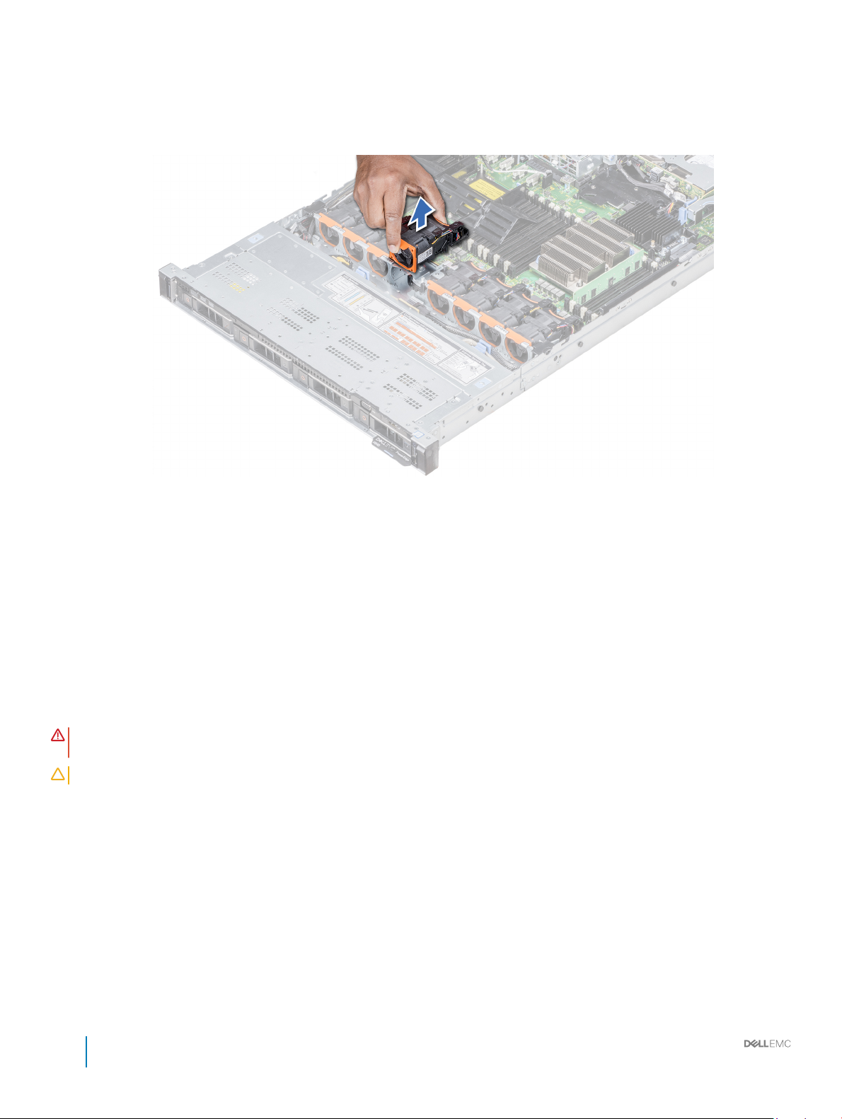
Steps
1 Holding the touch points on the cooling fan, lift the fan to disconnect the connector on the fan from the connector on the system
board.
2 Lift the fan out of the system.
Figure 30. Removing the cooling fan
Next steps
If applicable, install the cooling fan.
Related links
Installing a cooling fan
Installing a cooling fan
The procedure for installing standard and high performance fans is identical.
Prerequisites
WARNING
utmost care while removing or installing cooling fans.
CAUTION: The cooling fans are hot swappable. To maintain proper cooling while the system is on, replace only one fan at a time.
Follow the safety guidelines listed in Safety instructions.
Steps
1 Holding the touch points on the cooling fan, align the connector on the cooling fan with the connector on the system board.
2 Push the cooling fan, by pressing on the touch point, till the fan is rmly seated on the connector.
: Opening or removing the system cover when the system is on may expose you to a risk of electric shock. Exercise
78
Dell EMC PowerEdge R640 Installation and Service Manual
Installing and removing system components
Page 79

Figure 31. Installing the cooling fan
Next steps
Install the air shroud.
System memory
The system supports DDR4 registered DIMMs (RDIMMs), load reduced DIMMs (LRDIMMs) and non-volatile dual in-line DIMM-Ns
(NVDIMM-Ns). System memory holds the instructions that are executed by the processor.
NOTE
: MT/s indicates DIMM speed in MegaTransfers per second.
Memory bus operating frequency can be 2667 MT/s, 2400 MT/s, or 2133 MT/s depending on the following factors:
• DIMM type (RDIMM or LRDIMM)
• Number of DIMMs populated per channel
• System prole selected (for example, Performance Optimized, or Custom [can be run at high speed or lower])
• Maximum supported DIMM frequency of the processors
Your system contains 24 memory sockets split into two sets of 12 sockets, one set per processor. Each 12-socket set is organized into six
channels. In each channel, the release tabs of the rst socket are marked white, and the second socket black.
Dell EMC PowerEdge R640 Installation and Service Manual
Installing and removing system components
79
Page 80

Figure 32. System memory view
Memory channels are organized as follows:
Table 38. Memory channels
Proces
sor
Proces
sor 1
Proces
sor 2
80 Dell EMC PowerEdge R640 Installation and Service Manual
Channel 0 Channel 1 Channel 2 Channel 3 Channel 4 Channel 5
Slots A1 and A7 Slots A2 and A8 Slots A3 and A9 Slots A4 and A10 Slots A5 and A11 Slots A6 and A12
Slots B1 and B7 Slots B2 and B8 Slots B3 and B9 Slots B4 and B10 Slots B5 and B11 Slots B6 and B12
Installing and removing system components
Page 81

General memory module installation guidelines
NOTE: Memory congurations that fail to observe these guidelines can prevent your system from booting, stop responding
during memory conguration, or operate with reduced memory.
The system supports Flexible Memory Conguration, enabling the system to be congured and run in any valid chipset architectural
conguration. The following are the recommended guidelines for installing memory modules:
• RDIMMs and LRDIMMs must not be mixed.
• x4 and x8 DRAM based memory modules can be mixed. For more information, see the Mode-specic guidelines section.
• Up to two RDIMMs can be populated per channel regardless of rank count.
• Up to two LRDIMMs can be populated per channel regardless of rank count.
• If memory modules with dierent speeds are installed, they will operate at the speed of the slowest installed memory module(s) or
slower depending on the system DIMM conguration.
• Populate memory module sockets only if a processor is installed. For single-processor systems, sockets A1 to A12 are available. For dualprocessor systems, sockets A1 to A12 and sockets B1 to B12 are available.
• Populate all the sockets with white release tabs rst, followed by the black release tabs.
• When mixing memory modules with dierent capacities, populate the sockets with memory modules with highest capacity rst. For
example, if you want to mix 8 GB and 16 GB memory modules, populate 16 GB memory modules in the sockets with white release tabs
and 8 GB memory modules in the sockets with black release tabs.
• In a dual-processor conguration, the memory conguration for each processor should be identical. For example, if you populate socket
A1 for processor 1, then populate socket B1 for processor 2, and so on.
• Memory modules of dierent capacities can be mixed provided other memory population rules are followed (for example, 8 GB and 16
GB memory modules can be mixed).
• Mixing of more than two memory module capacities in a system is not supported.
• Populate six memory modules per processor (one DIMM per channel) at a time to maximize performance.
NVDIMM-N memory module installation guidelines
The following are the recommended guidelines for installing NVDIMM-N memory modules:
• Each system supports memory congurations with 1, 2, 4, 6, or 12 NVDIMM-Ns.
• Supported congurations have dual processors and a minimum of 12x RDIMMs.
• LRDIMMS and NVDIMM-Ns must not be mixed.
• Maximum of 12 NVDIMM-Ns can be installed in a system.
The following table lists the NVDIMM-N congurations that are currently supported on your system.
Table 39. Supported NVDIMM-N
Conguration Description Memory population rules
Conguration 1 12x 16 GB RDIMMs, 1x NVDIMM-N
Conguration 2 12x 32 GB RDIMMs, 1x NVDIMM-N
congurations
RDIMMs – C1{1,2,3,4,5,6}, C2{1,2,3,4,5,6}
NVDIMM-N – C1{7}
RDIMMs – Same for all 12x RDIMM
congurations. See Conguration 1
NVDIMM-N – C1{7},C2{7}
Dell EMC PowerEdge R640 Installation and Service Manual
Installing and removing system components
81
Page 82

Conguration Description Memory population rules
Conguration 3 23x 32 GB RDIMMs, 1x NVDIMM-N
RDIMMs – C1{1,2,3,4,5,6,7,8,9,10,11,12},
C2{1,2,3,4,5,6,7,8,9,10,11}
NVDIMM-N – C2{12}
Conguration 4 12x 16 GB RDIMMs, 2x NVDIMM-Ns
Conguration 5 12x 32 GB RDIMMs, 2x NVDIMM-Ns
Conguration 6 22x 32 GB RDIMMs, 2x NVDIMM-Ns
Conguration 7 12x 16 GB RDIMMs, 4x NVDIMM-Ns
Conguration 8 22x 32 GB RDIMMs, 4x NVDIMM-Ns
Conguration 9 20x 32 GB RDIMMs, 4x NVDIMM-Ns
RDIMMs – Same for all 12x RDIMM
congurations. See Cong 1
NVDIMM-N – C1{7}, C2{7}
RDIMMs – Same for all 12x RDIMM
congurations. See Cong 1
NVDIMM-N – C1{7}, C2{7}
RDIMMs – C1{1,2,3,4,5,6,7,8,9,10,11},
C2{1,2,3,4,5,6,7,8,9,10,11}
NVDIMM-N – C1{12}, C2{12}
RDIMMs – Same for all 12x RDIMM
congurations. See Cong 1
NVDIMM-N – C1{7,8}, C2{7,8}
RDIMMs – Same for all 12x RDIMM
congurations. See Cong 1
NVDIMM-N – C1{7,8}, C2{7,8}
RDIMMs – C1{1,2,3,4,5,6,7,8,9,10},
C2{1,2,3,4,5,6,7,8,9,10}
Conguration 10 12x 16 GB RDIMMs, 6x NVDIMM-Ns
Conguration 11 12x 32 GB RDIMMs, 6x NVDIMM-Ns
Conguration 12 18x 32 GB RDIMMs, 6x NVDIMM-Ns
Conguration 13 12x 16 GB RDIMMs, 12x NVDIMM-Ns
Conguration 14 12x 32 GB RDIMMs, 12x NVDIMM-Ns
NVDIMM-N – C1{11,12}, C2{11,12}
RDIMMs – Same for all 12x RDIMM
congurations. See Cong 1
NVDIMM-N – C1{7,8,9}, C2{7,8,9}
RDIMMs – Same for all 12x RDIMM
congurations. See Cong 1
NVDIMM-N – C1{7,8,9}, C2{7,8,9}
RDIMMs – C1{1,2,3,4,5,6,7,8,9},
C2{1,2,3,4,5,6,7,8,9}
NVDIMM-N – C1{10,11,12}, C2{10,11,12}
RDIMMs – Same for all 12x RDIMM
congurations. See Cong 1
NVDIMM-N – C1{7,8,9,10,11,12},
C2{7,8,9,10,11,12}
RDIMMs – Same for all 12x RDIMM
congurations. See Cong 1
82 Dell EMC PowerEdge R640 Installation and Service Manual
Installing and removing system components
Page 83

Conguration Description Memory population rules
NVDIMM-N – C1{7,8,9,10,11,12},
C2{7,8,9,10,11,12}
Mode-specic guidelines
Six memory channels are allocated to each processor. The congurations allowed depend on the memory mode selected.
Memory optimized (independent channel) mode
This mode supports Single Device Data Correction (SDDC) only for memory modules that use x4 device width. It does not impose any
specic slot population requirements.
Memory sparing
NOTE: To use memory sparing, this feature must be enabled in BIOS menu of System Setup.
Table 40. Memory sparing
Memory sparing (Single Rank) Memory sparing allocates one rank per channel as a spare. If
excessive correctable errors occur in a rank or channel, they are
moved to the spare area while the operating system is running to
prevent errors from causing an uncorrectable failure. Requires
population of two ranks or more per channel.
Memory sparing (Multi Rank) Memory sparing allocates two ranks per channel as a spare. If
excessive correctable errors occur in a rank or channel, they are
moved to the spare area while the operating system is running to
prevent errors from causing an uncorrectable failure. Requires
population of three ranks or more per channel.
With single rank memory sparing enabled, the system memory available to the operating system is reduced by one rank per channel. For
example, in a dual-processor conguration with twenty four 16 GB dual-rank memory modules, the available system memory is: 3/4 (ranks/
channel) × 24 (memory modules) × 16 GB = 288 GB, and not 24 (memory modules) × 16 GB = 384 GB. This calculation changes based on
if it is single rank sparing or multi rank sparing. For multi rank sparing, the multiplier changes to 1/2 (ranks/channel).
: Memory sparing does not oer protection against a multi-bit uncorrectable error.
NOTE
Memory mirroring
Memory mirroring oers the strongest memory module reliability mode, providing improved uncorrectable multi-bit failure protection. In a
mirrored conguration, the total available system memory is one half of the total installed physical memory. Half of the installed memory is
used to mirror the active memory modules. In the event of an uncorrectable error, the system switches over to the mirrored copy. This
ensures Single Device Data Correction (SDDC) and multi-bit protection.
The installation guidelines for memory modules are as follows:
• Memory modules must be identical in size, speed, and technology.
• Memory modules must be populated in sets of 6 per CPU to enable memory mirroring.
Dell EMC PowerEdge R640 Installation and Service Manual
Installing and removing system components
83
Page 84

Table 41. Memory population rules
Processor Conguration Memory population Memory population information
Single CPU Optimizer (Independent channel)
population order
Mirror population order {1, 2, 3, 4, 5, 6}, {7, 8, 9, 10, 11, 12} Mirroring is supported with 6 or 12
Single rank spare population order 1, 2, 3, 4, 5, 6, 7, 8, 9, 10, 11, 12 Populate in this order, odd amount
Multi rank spare population order 1, 2, 3, 4, 5, 6, 7, 8, 9, 10, 11, 12 Populate in this order, odd amount
Fault resilient population order {1, 2, 3, 4, 5, 6}, {7, 8, 9, 10, 11, 12} Supported with 6 or 12 DIMMs per
Dual CPU (Starting with
CPU1, CPU1 and CPU2
population should
match)
Optimized (Independent channel)
population order
Mirroring population order C1{1, 2, 3, 4, 5, 6}, C2{1, 2, 3, 4, 5,
Single rank sparing population order C1{1}, C2{1}, C1{2}, C2{2}, C1{3},
Multi rank spare population order C1{1}, C2{1}, C1{2}, C2{2}, C1{3},
Fault resilient population order C1{1, 2, 3, 4, 5, 6}, C2{1, 2, 3, 4, 5,
1, 2, 3, 4, 5, 6, 7, 8, 9, 10, 11, 12 Populate in this order, odd amount
allowed.
DIMMs per CPU.
allowed. Requires two ranks or more
per channel.
allowed. Requires three ranks or more
per channel.
CPU.
C1{1}, C2{1}, C1{2}, C2{2}, C1{3},
C2{3}...
6}, C1{7, 8, 9, 10, 11, 12}, C2{7, 8,
9, 10, 11, 12}
C2{3}...
C2{3}, C1{4}, C2{4}, C1{5},
C2{5}...
6}, C1{7, 8, 9, 10, 11, 12}, C2{7, 8,
9, 10, 11, 12}
Odd amount of DIMMs per CPU
allowed.
Mirroring is supported with 6 or 12
DIMMs per CPU.
Populate in this order, odd amount per
CPU allowed. Requires two ranks or
more per channel.
Populate in this order, odd amount per
CPU allowed. Requires three ranks or
more per channel.
Supported with 6 or 12 DIMMs per
CPU.
Removing a memory module
The procedure for removing a memory module and NVDIMM-N is identical.
Prerequisites
1 Follow the safety guidelines listed in Safety instructions.
2 Follow the procedure listed in Before working inside your system.
CAUTION
on NVDIMM-N and LEDs on NVDIMM-N battery are turned o before removing the NVDIMM-N battery.
3 If applicable, remove the air shroud.
WARNING
and avoid touching the components or metallic contacts on the memory module.
CAUTION: To ensure proper system cooling, memory module blanks must be installed in any memory socket that is not occupied.
Remove memory module blanks only if you intend to install memory modules in those sockets.
Steps
1 Locate the appropriate memory module socket.
84
: Allow the memory modules to cool after you power o the system. Handle the memory modules by the card edges
Dell EMC PowerEdge R640 Installation and Service Manual
Installing and removing system components
: To prevent data loss and potential damage to your system, ensure that your system, LEDs on system, LEDs
Page 85

CAUTION: Handle each memory module only by the card edges, ensuring not to touch the middle of the memory
module or metallic contacts.
2 Push the ejectors outward on both ends of the memory module socket to release the memory module from the socket.
3 Lift and remove the memory module from the system.
Figure 33. Removing a memory module
Next steps
1 Install the memory module.
2 If you are removing the memory module permanently, install a memory module blank. The procedure to install a memory module blank
is similar to that of the memory module.
Related links
Removing the air shroud
Installing a memory module
Installing a memory module
The procedure for installing a memory module and NVDIMM-N is identical.
Prerequisites
Follow the safety guidelines listed in Safety instructions.
CAUTION
CAUTION: To prevent data loss and potential damage to your system, ensure that your system, LEDs on system, LEDs on
NVDIMM-N and LEDs on NVDIMM-N battery are turned o before installing the NVDIMM-N battery.
CAUTION: To ensure proper system cooling, memory module blanks must be installed in any memory socket that is not occupied.
Remove memory module blanks only if you intend to install memory modules in those sockets.
Steps
1 Locate the appropriate memory module socket.
2 Open the ejectors on the memory module socket outward to allow the memory module to be inserted into the socket.
3 Align the edge connector of the memory module with the alignment key of the memory module socket, and insert the memory module
in the socket.
: Ensure that you install the NVDIMM-N battery if you are using NVDIMM-N.
CAUTION
module or metallic contacts.
CAUTION: To prevent damage to the memory module or the memory module socket during installation, do not bend or
ex the memory module. You must insert both ends of the memory module simultaneously.
: Handle each memory module only by the card edges, ensuring not to touch the middle of the memory
Dell EMC PowerEdge R640 Installation and Service Manual
Installing and removing system components
85
Page 86

CAUTION: Do not apply pressure at the center of the memory module; apply pressure at both ends of the memory
module evenly.
NOTE: The memory module socket has an alignment key that enables you to install the memory module in the socket in
only one orientation.
4 Press the memory module with your thumbs until the socket levers rmly click into place.
Figure 34. Installing a memory module
Next steps
1 If applicable, install the air shroud.
2 Follow the procedure listed in After working inside your system.
3 To verify if the memory module has been installed properly, press F2 and navigate to System Setup Main Menu > System BIOS >
Memory Settings. In the Memory Settings screen, the System Memory Size must reect the updated capacity of the installed
memory.
4 If the value is incorrect, one or more of the memory modules may not be installed properly. Ensure that the memory module is rmly
seated in the memory module socket.
5 Run the system memory test in system diagnostics.
Related links
Installing the air shroud
NVDIMM-N battery
NVDIMM-N battery can be installed on the SAS expander board.
Removing the NVDIMM-N battery
Prerequisites
1 Follow the safety guidelines listed in Safety instructions.
2 Follow the procedure listed in Before working inside your system.
CAUTION
o before removing the NVDIMM-N battery.
86 Dell EMC PowerEdge R640 Installation and Service Manual
Installing and removing system components
: To prevent data loss, ensure that your system and LEDs on NVDIMM-N and NVDIMM-N battery are turned
Page 87
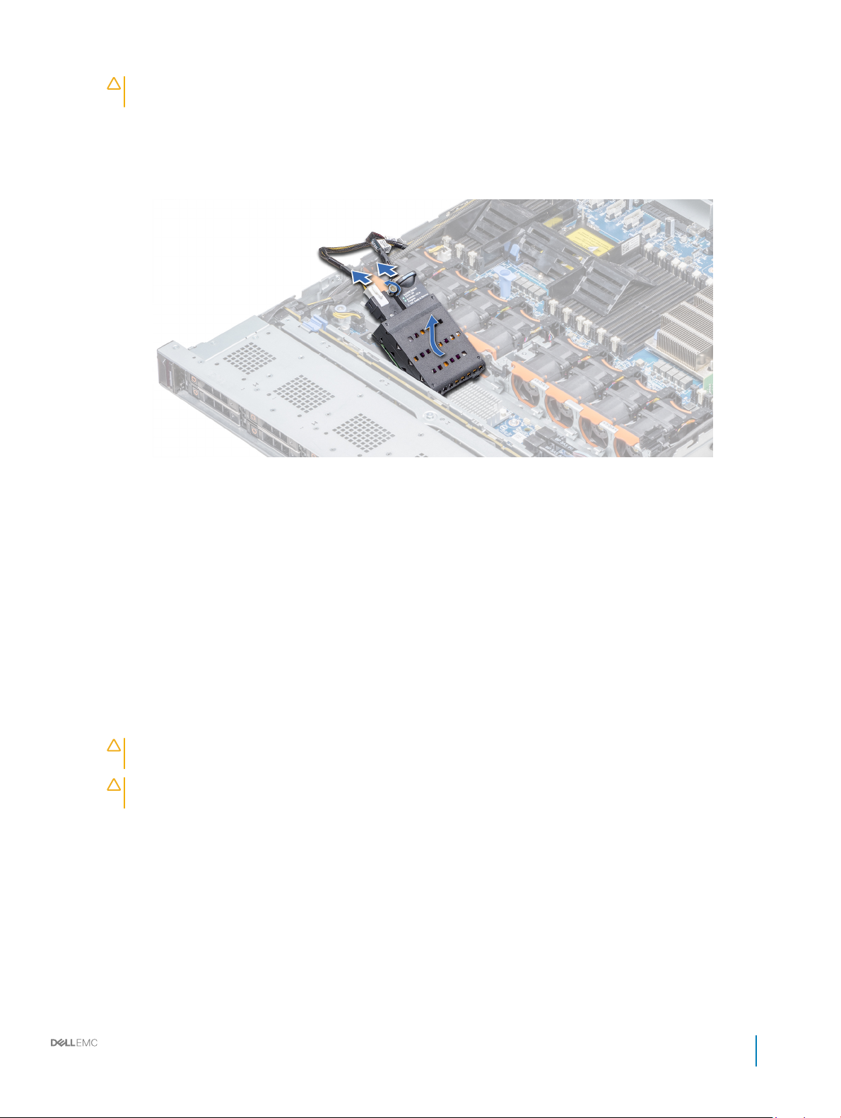
CAUTION: To avoid damage to the battery connector, you must rmly support the connector while installing or
removing a battery.
3 Disconnect the cables from the NVDIMM-N battery.
Steps
1 Using the Phillips #2 screwdriver, loosen the screw securing the NVDIMM-N battery.
2 Holding the edges, lift the NVDIMM-N battery away from the system.
Figure 35. Removing the NVDIMM-N battery
Next steps
1 Install the NVDIMM-N battery.
Related links
Installing the NVDIMM-N battery
Installing the NVDIMM-N battery
Prerequisites
1 Follow the safety guidelines listed in Safety instructions.
CAUTION
o before removing the NVDIMM-N battery.
CAUTION: To avoid damage to the battery connector, you must rmly support the connector while installing or
removing a battery.
Steps
1 Holding the edges, align the NVDIMM-N battery with the battery connector on the system board
2 Connect the cables to the NVDIMM-N battery.
3 Using the Phillips #2 screwdriver, tighten the screw to secure the NVDIMM-N battery.
: To prevent data loss, ensure that your system and LEDs on NVDIMM-N and NVDIMM-N battery are turned
Dell EMC PowerEdge R640 Installation and Service Manual
Installing and removing system components
87
Page 88

Figure 36. Installing the NVDIMM-N battery
Next steps
1 Follow the procedure listed in After working inside your system.
Processors and heat sinks
The processor controls memory, peripheral interfaces, and other components of the system. The system can have more than one
processor congurations.
The heat sink absorbs the heat generated by the processor, and helps the processor to maintain its optimal temperature level.
Removing a processor and heat sink module
Prerequisites
WARNING
cool before removing it.
1 Follow the safety guidelines listed in Safety instructions.
2 Follow the procedure listed in Before working inside your system.
Steps
1 Using a Torx #T30 screwdriver, loosen the screws on the heat sink.
2 Pushing both retention clips simultaneously, lift the processor and heat sink module (PHM) out of the system.
3 Set the PHM module aside with the processor side facing up.
88
: The heat sink may be hot to touch for some time after the system has been powered down. Allow the heat sink to
NOTE
: Ensure that you loosen one screw before moving on to the next screw.
Dell EMC PowerEdge R640 Installation and Service Manual
Installing and removing system components
Page 89

Figure 37. Removing the processor and heat sink module
Next steps
1 Install the PHM module.
Related links
Installing a processor and heat sink module
Removing the processor from the processor and heat sink module
Prerequisites
WARNING
cool before removing it.
1 Follow the safety guidelines listed in Safety instructions.
2 Follow the procedure listed in Before working inside your system.
3 Remove the air shroud.
4 Remove the processor and heat sink module.
Steps
1 Place the heat sink with the processor side facing up.
2 Insert a at blade screwdriver into the release slot marked with a yellow label. Twist (do not pry) the screwdriver to break the thermal
paste seal.
3 Push the retaining clips on the processor bracket to unlock the bracket from the heat sink.
: The heat sink may be hot to touch for some time after the system has been powered down. Allow the heat sink to
Dell EMC PowerEdge R640 Installation and Service Manual
Installing and removing system components
89
Page 90

Figure 38. Loosening the processor bracket
4 Lift the bracket and the processor away from the heat sink, and place the processor connector side down on the processor tray.
5 Flex the outer edges of the bracket to release the processor from the bracket.
NOTE
: Ensure that the processor and the bracket are placed in the tray after you remove the heat sink.
Figure 39. Removing the processor bracket
Next steps
Install the processor into the processor and heat sink module.
Related links
Removing the air shroud
Removing a processor and heat sink module
Installing the processor into a processor and heat sink module
90
Dell EMC PowerEdge R640 Installation and Service Manual
Installing and removing system components
Page 91

Installing the processor into a processor and heat sink module
Prerequisites
Follow the safety guidelines listed in Safety instructions.
Steps
1 Place the processor in the processor tray.
NOTE: Ensure that pin 1 indicator on the processor tray is aligned with the pin 1 indicator on the processor.
2 Flex the outer edges of the bracket around the processor ensuring that the processor is locked into the clips on the bracket.
NOTE: Ensure that pin 1 indicator on the bracket is aligned with the pin 1 indicator on the processor before placing the
bracket on the processor.
NOTE: Ensure that the processor and the bracket are placed in the tray before you install the heat sink.
Figure 40. Installing the processor bracket
3 If you are using an existing heat sink, remove the thermal grease from the heat sink by using a clean lint-free cloth.
4 Use the thermal grease syringe included with your processor kit to apply the grease in a quadrilateral design on the top of the
processor.
CAUTION
processor socket.
NOTE: The thermal grease syringe is intended for single use only. Dispose the syringe after you use it.
: Applying too much thermal grease can result in excess grease coming in contact with and contaminating the
Dell EMC PowerEdge R640 Installation and Service Manual
Installing and removing system components
91
Page 92

Figure 41. Applying thermal grease on top of the processor
5 Place the heat sink on the processor and push down until the bracket locks onto the heat sink.
NOTE
:
• Ensure that the two guide pin holes on the bracket match the guide holes on the heat sink.
• Ensure that the pin 1 indicator on the heat sink is aligned with the pin 1 indicator on the bracket before placing the heat
sink onto the processor and bracket.
92 Dell EMC PowerEdge R640 Installation and Service Manual
Installing and removing system components
Page 93

Figure 42. Installing the heat sink onto the processor
Next steps
1 Install the processor and heat sink module.
2 Install the air shroud.
3 Follow the procedure listed in After working inside your system.
Installing a processor and heat sink module
Prerequisites
CAUTION
maintain proper thermal conditions.
WARNING: The heat sink may be hot to touch for some time after the system has been powered down. Allow the heat sink to
cool before removing it.
1 Follow the safety guidelines listed in Safety instructions.
2 If installed, remove the processor/DIMM blank and CPU dust cover.
The procedure to remove the processor/DIMM blank is similar to that of the memory module.
Steps
1 Align the Pin1 indicator of the heat sink to the system board and then place the processor and heat sink module (PHM) on the
processor socket.
: Never remove the heat sink from a processor unless you intend to replace the processor. The heat sink is necessary to
CAUTION
ns.
: To avoid damaging the ns on the heat sink, do not press down on the heat sink
Dell EMC PowerEdge R640 Installation and Service Manual
Installing and removing system components
93
Page 94

NOTE: Ensure that the PHM module is held parallel to the system board to prevent damaging the components.
2 Push the blue retention clips inward to allow the heat sink to drop into place.
3 Using the #Torx T30 screwdriver, tighten one screw at a time.
NOTE: Ensure that the screw is tightened completely before moving onto the next screw.
NOTE: The processor and heat sink module retention screws should not be tightened to more than 0.13 kgf-m (1.35 N.m
or 12 in-lbf).
Figure 43. Installing a processor and heat sink module
Next steps
1 Follow the procedure listed in After working inside your system.
Expansion cards and expansion card risers
An expansion card in the system is an add-on card that can be inserted into an expansion slot on the system board or riser card to add
enhanced functionality to the system through the expansion bus.
: A System Event Log (SEL) event is logged if an expansion card riser is not supported or missing. It does not prevent your
NOTE
system from turning on but, F1/F2 pause occurs and an error message is displayed.
Expansion bus specications
The PowerEdge R640 system supports PCI express (PCIe) generation 3 expansion cards, which are installed on the system, using
expansion card risers. This system supports 1A, 2A, 1B, and 2B expansion card risers.
94
Dell EMC PowerEdge R640 Installation and Service Manual
Installing and removing system components
Page 95

Expansion card installation guidelines
Depending on your system conguration, the following PCI Express (PCIe) generation 3 expansion cards are supported:
Table 42. Expansion card riser congurations
Expansion card riser PCIe slots on the riser Processor connection Height Length Slot width
Riser 1A Slot 1 Processor 1 Low Prole Half Length x16
Slot 2 Processor 1 Low Prole Half Length x16
Riser 2A Slot 3 Processor 2 Low Prole Half Length x16
Riser 1B Slot 1 Processor 1 Low Prole Half Length x16
Riser 2B Slot 2 Processor 2 Full Height Three-fourth Length x16
Riser 1B Slot 1 Processor 1 Low Prole Half Length x16
NOTE: The expansion card slots are not hot-swappable.
The following table provides guidelines for installing expansion cards to ensure proper cooling and mechanical t. The expansion cards with
the highest priority should be installed rst using the slot priority indicated. All the other expansion cards should be installed in the card
priority and slot priority order.
Table 43. Riser congurations: 1B
Card Type Slot Priority Form Factor
HWRAID BOSS (ODM) 1 Low Prole
NVMe PCIe SSD (Dell design) 1 Low Prole
Inniband HCA EDR (Mellanox) 1 Low Prole
100G NICs (Mellanox) 1 Low Prole
Omni-Path HFI (Intel) 1 Low Prole
Inniband HCA FDR (Mellanox) 1 Low Prole
40G NICs (Intel) 1 Low Prole
40G NICs (Mellanox) 1 Low Prole
FC32 HBA (QLogic) 1 Low Prole
FC32 HBA (Emulex) 1 Low Prole
25G NICs (Broadcom) 1 Low Prole
25G NICs (Mellanox) 1 Low Prole
25G NICs (QLogic) 1 Low Prole
FC16 HBA (QLogic) 1 Low Prole
FC16 HBA (Emulex) 1 Low Prole
10Gb NICs (Broadcom) 1 Low Prole
10Gb NICs (Intel) 1 Low Prole
10Gb NICs (Mellanox) 1 Low Prole
Dell EMC PowerEdge R640 Installation and Service Manual
Installing and removing system components
95
Page 96

Card Type Slot Priority Form Factor
10Gb NICs (QLogic) 1 Low Prole
10Gb NICs (Solarare) 1 Low Prole
FC8 HBA (Emulex) 1 Low Prole
FC8 HBA (QLogic) 1 Low Prole
1Gb NICs (Broadcom) 1 Low Prole
1Gb NICs (Intel) 1 Low Prole
Adapter RAID (Dell design) 1 Low Prole
External RAID (Dell design) 1 Low Prole
Non-RAID (Dell design) 1 Low Prole
Integrated RAID (Dell design) Integrated Slot NONE
rNDC (Broadcom) Integrated Slot NONE
rNDC (Intel) Integrated Slot NONE
rNDC (Mellanox) Integrated Slot NONE
rNDC (QLogic) Integrated Slot NONE
Table 44. Riser congurations: 1A + 2A
Card type Slot priority Form factor
Adapter RAID (Dell design) 1 Low Prole
HWRAID BOSS (ODM) 1, 2, 3 Low Prole
NVMe PCIe SSD (Dell design) 1, 2, 3 Low Prole
Inniband HCA EDR (Mellanox) 1, 2, 3 Low Prole
100G NICs (Mellanox) 1, 2, 3 Low Prole
Omni-Path HFI (Intel) 1, 2, 3 Low Prole
Inniband HCA FDR (Mellanox) 1, 2, 3 Low Prole
40G NICs (Intel) 1, 2, 3 Low Prole
40G NICs (Mellanox) 1, 2, 3 Low Prole
FC32 HBA (QLogic) 1, 2, 3 Low Prole
FC32 HBA (Emulex) 1, 2, 3 Low Prole
25G NICs (Broadcom) 1, 2, 3 Low Prole
25G NICs (Mellanox) 1, 2, 3 Low Prole
25G NICs (QLogic) 1, 2, 3 Low Prole
FC16 HBA (QLogic) 1, 2, 3 Low Prole
FC16 HBA (Emulex) 1, 2, 3 Low Prole
10Gb NICs (Broadcom) 1, 2, 3 Low Prole
10Gb NICs (Intel) 1, 2, 3 Low Prole
10Gb NICs (Mellanox) 1, 2, 3 Low Prole
96 Dell EMC PowerEdge R640 Installation and Service Manual
Installing and removing system components
Page 97

Card type Slot priority Form factor
10Gb NICs (QLogic) 1, 2, 3 Low Prole
10Gb NICs (Solarare) 1, 2, 3 Low Prole
FC8 HBA (Emulex) 1, 3 Low Prole
FC8 HBA (QLogic) 1, 2, 3 Low Prole
1Gb NICs (Broadcom) 1, 2, 3 Low Prole
1Gb NICs (Intel) 1, 2, 3 Low Prole
External RAID (Dell design) 1, 2, 3 Low Prole
Non-RAID (Dell design) 1, 3 Low Prole
Integrated RAID (Dell design) Integrated Slot NONE
rNDC (Broadcom) Integrated Slot NONE
rNDC (Intel) Integrated Slot NONE
rNDC (Mellanox) Integrated Slot NONE
rNDC (QLogic) Integrated Slot NONE
Table 45. Riser congurations: 1B + 2B
Card type Slot priority Form factor
HWRAID BOSS (ODM) 1 Low Prole
NVMe PCIe SSD (Dell design) 1 Low Prole
Inniband HCA EDR (Mellanox) 1 Low Prole
100G NICs (Mellanox) 1 Low Prole
Omni-Path HFI (Intel) 1 Low Prole
Inniband HCA FDR (Mellanox) 1 Low Prole
40G NICs (Intel) 1 Low Prole
40G NICs (Mellanox) 1 Low Prole
FC32 HBA (QLogic) 1 Low Prole
FC32 HBA (Emulex) 1 Low Prole
25G NICs (Broadcom) 1 Low Prole
25G NICs (Mellanox) 1 Low Prole
25G NICs (QLogic) 1 Low Prole
FC16 HBA (QLogic) 1 Low Prole
FC16 HBA (Emulex) 1 Low Prole
10Gb NICs (Broadcom) 1 Low Prole
10Gb NICs (Intel) 1 Low Prole
10Gb NICs (Mellanox) 1 Low Prole
10Gb NICs (QLogic) 1 Low Prole
10Gb NICs (Solarare) 1 Low Prole
Dell EMC PowerEdge R640 Installation and Service Manual
Installing and removing system components
97
Page 98

Card type Slot priority Form factor
FC8 HBA (Emulex) 1 Low Prole
FC8 HBA (QLogic) 1 Low Prole
1Gb NICs (Broadcom) 1 Low Prole
1Gb NICs (Intel) 1 Low Prole
Adapter RAID (Dell design) 1 Low Prole
External RAID (Dell design) 1 Low Prole
Non-RAID (Dell design) 1 Low Prole
HWRAID BOSS (ODM) 2 Full Height
Inniband HCA EDR (Mellanox) 2 Full Height
100G NICs (Mellanox) 2 Full Height
Omni-Path HFI (Intel) 2 Full Height
40G NICs (Intel) 2 Full Height
40G NICs (Mellanox) 2 Full Height
FC32 HBA (QLogic) 2 Full Height
FC32 HBA (Emulex) 2 Full Height
25G NICs (Broadcom) 2 Full Height
25G NICs (Mellanox) 2 Full Height
25G NICs (QLogic) 2 Full Height
FC16 HBA (QLogic) 2 Full Height
FC16 HBA (Emulex) 2 Full Height
10Gb NICs (Broadcom) 2 Full Height
10Gb NICs (Intel) 2 Full Height
10Gb NICs (Mellanox) 2 Full Height
10Gb NICs (QLogic) 2 Full Height
10Gb NICs (Solarare) 2 Full Height
FC8 HBA (Emulex) 2 Full Height
FC8 HBA (QLogic) 2 Full Height
1Gb NICs (Broadcom) 2 Full Height
1Gb NICs (Intel) 2 Full Height
External RAID (Dell design) 2 Full Height
Non-RAID (Dell design) 2 Full Height
Low-end Vedio (Dell design) 2 Full Height
Integrated RAID (Dell design) Integrated Slot NONE
rNDC (Broadcom) Integrated Slot NONE
rNDC (Intel) Integrated Slot NONE
rNDC (Mellanox) Integrated Slot NONE
98 Dell EMC PowerEdge R640 Installation and Service Manual
Installing and removing system components
Page 99

Card type Slot priority Form factor
rNDC (QLogic) Integrated Slot NONE
Table 46. Riser congurations:1A
Card type Slot priority Form factor
Adapter RAID (Dell design) 1 Low Prole
Non-RAID (Dell design) 1 Low Prole
HWRAID BOSS (ODM) 1, 2 Low Prole
NVMe PCIe SSD (Dell design) 1, 2 Low Prole
Inniband HCA EDR (Mellanox) 1, 2 Low Prole
100G NICs (Mellanox) 1, 2 Low Prole
Omni-Path HFI (Intel) 1, 2 Low Prole
Inniband HCA FDR (Mellanox) 1, 2 Low Prole
40G NICs (Intel) 1, 2 Low Prole
40G NICs (Mellanox) 1, 2 Low Prole
FC32 HBA (QLogic) 1, 2 Low Prole
FC32 HBA (Emulex) 1, 2 Low Prole
25G NICs (Broadcom) 1, 2 Low Prole
25G NICs (Mellanox) 1, 2 Low Prole
25G NICs (QLogic) 1, 2 Low Prole
FC16 HBA (QLogic) 1, 2 Low Prole
FC16 HBA (Emulex) 1, 2 Low Prole
10Gb NICs (Broadcom) 1, 2 Low Prole
10Gb NICs (Intel) 1, 2 Low Prole
10Gb NICs (Mellanox) 1, 2 Low Prole
10Gb NICs (QLogic) 1, 2 Low Prole
10Gb NICs (Solarare) 1, 2 Low Prole
FC8 HBA (Emulex) 1 Low Prole
FC8 HBA (QLogic) 1, 2 Low Prole
1Gb NICs (Broadcom) 1, 2 Low Prole
1Gb NICs (Intel) 1, 2 Low Prole
External RAID (Dell design) 1, 2 Low Prole
Integrated RAID (Dell design) Integrated Slot NONE
rNDC (Broadcom) Integrated Slot NONE
rNDC (Intel) Integrated Slot NONE
rNDC (Mellanox) Integrated Slot NONE
rNDC (QLogic) Integrated Slot NONE
Dell EMC PowerEdge R640 Installation and Service Manual
Installing and removing system components
99
Page 100

Removing an expansion card riser
Prerequisites
1 Follow the safety guidelines listed in Safety instructions.
2 Follow the procedure listed in Before working inside your system.
3 Before removing the expansion card riser 2A, remove the expansion card from the riser, if installed.
4 Disconnect any cables connected to the expansion card.
Steps
Hold the touch points, and lift the expansion card riser, from the riser connector, on the system board.
NOTE: While removing the riser 1B, press the tabs and hold the touch point to lift the expansion card riser from the
system board.
Figure 44. Removing the expansion riser 1B
100
Dell EMC PowerEdge R640 Installation and Service Manual
Installing and removing system components
 Loading...