

Page 1

Wyse 5470 All-in-One Thin Client
Service Manual
Page 2

Notes, cautions, and warnings
NOTE: A NOTE indicates important information that helps you make better use of your product.
CAUTION: A CAUTION indicates either potential damage to hardware or loss of data and tells you how to avoid the
problem.
WARNING: A WARNING indicates a potential for property damage, personal injury, or death.
© 2018 - 2019 Dell Inc. or its subsidiaries. All rights reserved. Dell, EMC, and other trademarks are trademarks of Dell Inc. or its
subsidiaries. Other trademarks may be trademarks of their respective owners.
2019 - 08
Rev. A00
Page 3

Contents
1 Working on your thin client............................................................................................................5
Safety instructions................................................................................................................................................................ 5
Before working on your thin client...................................................................................................................................... 5
Safety precautions................................................................................................................................................................ 6
Electrostatic discharge—ESD protection.......................................................................................................................... 6
ESD field service kit ..............................................................................................................................................................7
Transporting sensitive components.................................................................................................................................... 7
After working on your thin client......................................................................................................................................... 8
2 Removing and installing components............................................................................................. 9
Recommended tools..............................................................................................................................................................9
Screw list................................................................................................................................................................................ 9
Stand......................................................................................................................................................................................10
Removing the easel stand............................................................................................................................................. 10
Installing the easel stand................................................................................................................................................12
Back cover............................................................................................................................................................................ 14
Removing the back cover..............................................................................................................................................14
Installing the back cover................................................................................................................................................15
Vesa-mount bracket............................................................................................................................................................ 16
Removing the VESA-mount bracket........................................................................................................................... 16
Installing the VESA-mount bracket.............................................................................................................................. 17
On-screen display board......................................................................................................................................................18
Removing the OSD board............................................................................................................................................. 18
Installing the OSD board................................................................................................................................................19
Solid-state drive...................................................................................................................................................................20
Removing the solid-state drive....................................................................................................................................20
Installing the solid-state drive....................................................................................................................................... 21
Memory module...................................................................................................................................................................22
Removing the memory modules ................................................................................................................................. 22
Installing the memory modules.....................................................................................................................................23
Wireless card........................................................................................................................................................................24
Removing the wireless card......................................................................................................................................... 24
Installing the wireless card............................................................................................................................................25
Heat sink...............................................................................................................................................................................26
Removing the heat sink................................................................................................................................................ 26
Installing the heat sink...................................................................................................................................................27
Coin-cell battery.................................................................................................................................................................. 28
Removing the coin-cell battery....................................................................................................................................28
Installing the coin-cell battery...................................................................................................................................... 29
Camera..................................................................................................................................................................................30
Removing the camera...................................................................................................................................................30
Installing the camera...................................................................................................................................................... 31
System board....................................................................................................................................................................... 32
Removing the system board........................................................................................................................................ 32
Contents 3
Page 4

Installing the system board...........................................................................................................................................33
Speakers............................................................................................................................................................................... 35
Removing the speakers................................................................................................................................................ 35
Installing the speakers...................................................................................................................................................35
Middle frame........................................................................................................................................................................ 36
Removing the middle frame......................................................................................................................................... 36
Installing the middle frame............................................................................................................................................37
Rubber feet.......................................................................................................................................................................... 39
Removing the rubber feet............................................................................................................................................ 39
Installing the rubber feet...............................................................................................................................................39
Display panel.........................................................................................................................................................................40
Removing the display panel..........................................................................................................................................40
Installing the display panel............................................................................................................................................. 41
3 System setup.............................................................................................................................43
System Setup overview......................................................................................................................................................43
Accessing thin client BIOS settings...................................................................................................................................43
Navigation keys....................................................................................................................................................................43
Boot Sequence.................................................................................................................................................................... 44
General screen options....................................................................................................................................................... 44
System Configuration screen options...............................................................................................................................45
Video screen option.............................................................................................................................................................46
Security screen options...................................................................................................................................................... 47
Secure Boot screen options...............................................................................................................................................48
Intel Software Guard Extensions screen options............................................................................................................ 49
Performance screen options..............................................................................................................................................49
Power management screen options................................................................................................................................. 50
POST behavior screen options...........................................................................................................................................51
Wireless screen option.........................................................................................................................................................51
Virtualization support screen options................................................................................................................................ 51
Maintenance screen options..............................................................................................................................................52
System Logs screen option................................................................................................................................................52
Advanced configurations....................................................................................................................................................52
4
4 Troubleshooting your system...................................................................................................... 53
Enhanced Pre-Boot System Assessment diagnostics....................................................................................................53
Running the ePSA diagnostics.....................................................................................................................................53
Power behavior....................................................................................................................................................................54
Power state and LED status..............................................................................................................................................55
5 Getting help.............................................................................................................................. 56
Contacting Dell.................................................................................................................................................................... 56
Contents
Page 5

1
Working on your thin client
Safety instructions
Prerequisites
Use the following safety guidelines to protect your thin client from potential damage and to ensure your personal safety. Unless otherwise
noted, each procedure included in this document assumes that the following conditions exist:
• You have read the safety information that shipped with your thin client.
• A component can be replaced or, if purchased separately, installed by performing the removal procedure in reverse order.
About this task
WARNING: Disconnect all power sources before opening the thin client cover or panels. After you finish working inside
the computer, replace all covers, panels, and screws before connecting to the electrical outlet.
NOTE: Before working on your thin client, read the safety information that shipped with your thin client. For additional
safety best practices information, see the Regulatory Compliance home page at www.Dell.com/regulatory_compliance.
CAUTION: Many repairs may only be done by a certified service technician. You should only perform troubleshooting and
simple repairs as authorized in your product documentation, or as directed by the online or telephone service and
support team. Damage due to servicing that is not authorized by Dell is not covered by your warranty. Read and follow
the safety instructions that ship with the product.
CAUTION: To avoid electrostatic discharge, ground yourself by using a wrist grounding strap or by periodically touching
an unpainted metal surface at the same time as touching a connector on the back of the thin client.
CAUTION: Handle components and cards with care. Do not touch the components or contacts on a card. Hold a card by
its edges or by its metal mounting bracket. Hold a component such as a processor by its edges, not by its pins.
CAUTION: When you disconnect a cable, pull on its connector or on its pull-tab, not on the cable itself. Some cables
have connectors with locking tabs; if you are disconnecting this type of cable, press in on the locking tabs before you
disconnect the cable. As you pull connectors apart, keep them evenly aligned to avoid bending any connector pins. Also,
before you connect a cable, ensure that both connectors are correctly oriented and aligned.
NOTE: The color of your thin client and certain components may appear differently than shown in this document.
Before working on your thin client
You must perform the below steps before you work on the thin client.
About this task
NOTE:
regulatory_compliance.
Steps
1. Save and close all open files and exit all open applications.
2. Click Start > Power > Shut down to shut down your thin client.
For more safety best practices, see the Regulatory Compliance home page at www.Dell.com/
NOTE:
3. Disconnect your thin client and all the attached devices from their electrical outlets.
For shut down instructions, see documentation of the respective operating system.
Working on your thin client 5
Page 6

4. Disconnect all network cables from your thin client.
5. Disconnect all attached devices and peripherals, such as keyboard, mouse, and monitor, from your thin client.
Safety precautions
The safety precautions chapter details the primary steps to be taken before performing any disassembly instructions.
Observe the following safety precautions before you perform any installation or break/fix procedures involving disassembly or reassembly:
• Turn off the system and all attached peripherals.
• Disconnect the system and all attached peripherals from AC power.
• Disconnect all network cables, telephone, and telecommunications lines from the system.
• Use an ESD field service kit when working inside any tabletnotebookdesktop to avoid electrostatic discharge (ESD) damage.
• After removing any system component, carefully place the removed component on an anti-static mat.
• Wear shoes with non-conductive rubber soles to reduce the chance of getting electrocuted.
Standby power
Dell products with standby power must be unplugged before you open the case. Systems that incorporate standby power are essentially
powered while turned off. The internal power enables the system to be remotely turned on (wake on LAN) and suspended into a sleep
mode and has other advanced power management features.
Unplugging, pressing and holding the power button for 15 seconds should discharge residual power in the system board. Remove the
battery from portablestabletsnotebooks.
Bonding
Bonding is a method for connecting two or more grounding conductors to the same electrical potential. This is done through the use of a
field service electrostatic discharge (ESD) kit. When connecting a bonding wire, ensure that it is connected to bare metal and never to a
painted or non-metal surface. The wrist strap should be secure and in full contact with your skin, and ensure that you remove all jewelry
such as watches, bracelets, or rings prior to bonding yourself and the equipment.
Electrostatic discharge—ESD protection
ESD is a major concern when you handle electronic components, especially sensitive components such as expansion cards, processors,
memory DIMMs, and system boards. Very slight charges can damage circuits in ways that may not be obvious, such as intermittent
problems or a shortened product life span. As the industry pushes for lower power requirements and increased density, ESD protection is
an increasing concern.
Due to the increased density of semiconductors used in recent Dell products, the sensitivity to static damage is now higher than in
previous Dell products. For this reason, some previously approved methods of handling parts are no longer applicable.
Two recognized types of ESD damage are catastrophic and intermittent failures.
• Catastrophic—Catastrophic failures represent approximately 20 percent of ESD-related failures. The damage causes an immediate
and complete loss of device functionality. An example of catastrophic failure is a memory DIMM that has received a static shock and
immediately generates a "No POST/No Video" symptom with a beep code emitted for missing or nonfunctional memory.
• Intermittent—Intermittent failures represent approximately 80 percent of ESD-related failures. The high rate of intermittent failures
means that most of the time when damage occurs, it is not immediately recognizable. The DIMM receives a static shock, but the
tracing is merely weakened and does not immediately produce outward symptoms related to the damage. The weakened trace may
take weeks or months to melt, and in the meantime may cause degradation of memory integrity, intermittent memory errors, etc.
The more difficult type of damage to recognize and troubleshoot is the intermittent (also called latent or "walking wounded") failure.
Perform the following steps to prevent ESD damage:
• Use a wired anti-static wrist strap that is properly grounded. The use of wireless anti-static wrist straps is no longer allowed because
they do not provide adequate protection. Touching the chassis before handling parts does not ensure adequate ESD protection on
parts with increased sensitivity to ESD damage.
• Handle all static-sensitive components in a static-safe area. If possible, use anti-static floor pads and workbench pads.
• When unpacking a static-sensitive component from its shipping carton, do not remove the component from the anti-static packing
material until you are ready to install the component. Before unwrapping the anti-static packaging, ensure that you discharge static
electricity from your body.
• Before transporting a static-sensitive component, place it in an anti-static container or packaging.
Working on your thin client
6
Page 7

ESD field service kit
The unmonitored Field Service kit is the most commonly used service kit. Each Field Service kit includes three main components: antistatic mat, anti-static wrist strap, and bonding wire.
Components of an ESD field service kit
The components of an ESD field service kit are:
• Anti-static mat—The anti-static mat is dissipative and parts can be placed on it during service procedures. When using an anti-static
mat, your anti-static wrist strap should be snug and the bonding wire should be connected to the mat and to any bare metal on the
system being worked on. Once deployed properly, service parts can be removed from the ESD bag and placed directly on the mat.
ESD-sensitive items are safe in your hand, on the ESD mat, in the system, or inside a bag.
• Anti-static wrist strap and bonding wire—The anti-static wrist strap and bonding wire can be either directly connected between
your wrist and bare metal on the hardware if the ESD mat is not required, or connected to the anti-static mat to protect hardware
that is temporarily placed on the mat. The physical connection of the anti-staticwrist strap and bonding wire between your skin, the
ESD mat, and the hardware is known as bonding. Use only Field Service kits with an anti-static wrist strap, mat, and bonding wire.
Never use wireless anti-static wrist straps. Always be aware that the internal wires of a anti-static wrist strap are prone to damage
from normal wear and tear, and must be checked regularly with a anti-static wrist strap tester in order to avoid accidental ESD
hardware damage. It is recommended to test the anti-static wrist strap and bonding wire at least once per week.
• ESD wrist strap tester—The wires inside of an ESD strap are prone to damage over time. When using an unmonitored kit, it is a
best practice to regularly test the strap prior to each service call, and at a minimum, test once per week. A wrist strap tester is the
best method for doing this test. If you do not have your own wrist strap tester, check with your regional office to find out if they have
one. To perform the test, plug the wrist-strap's bonding-wire into the tester while it is strapped to your wrist and push the button to
test. A green LED is lit if the test is successful; a red LED is lit and an alarm sounds if the test fails.
• Insulator Elements —It is critical to keep ESD sensitive devices, such as plastic heat sink casings, away from internal parts that are
insulators and often highly charged.
• Working Environment – Before deploying the ESD Field Service kit, assess the situation at the customer location. For example,
deploying the kit for a server environment is different than for a desktop or portable environment. Servers are typically installed in a
rack within a data center; desktops or portables are typically placed on office desks or cubicles. Always look for a large open flat work
area that is free of clutter and large enough to deploy the ESD kit with additional space to accommodate the type of system that is
being repaired. The workspace should also be free of insulators that can cause an ESD event. On the work area, insulators such as
Styrofoam and other plastics should always be moved at least 12 inches or 30 centimeters away from sensitive parts before physically
handling any hardware components
• ESD Packaging – All ESD-sensitive devices must be shipped and received in static-safe packaging. Metal, static-shielded bags are
preferred. However, you should always return the damaged part using the same ESD bag and packaging that the new part arrived in.
The ESD bag should be folded over and taped shut and all the same foam packing material should be used in the original box that the
new part arrived in. ESD-sensitive devices should be removed from packaging only at an ESD-protected work surface, and parts
should never be placed on top of the ESD bag because only the inside of the bag is shielded. Always place parts in your hand, on the
ESD mat, in the system, or inside an anti-static bag.
• Transporting Sensitive Components – When transporting ESD sensitive components such as replacement parts or parts to be
returned to Dell, it is critical to place these parts in anti-static bags for safe transport.
ESD protection summary
It is recommended that all field service technicians use the traditional wired ESD grounding anti-static wrist strap and protective antistatic mat at all times when servicing Dell products. In addition, it is critical that technicians keep sensitive parts separate from all insulator
parts while performing service and that they use anti-static bags for transporting sensitive components.
Transporting sensitive components
When transporting ESD sensitive components such as replacement parts or parts to be returned to Dell, it is critical to place these parts in
anti-static bags for safe transport.
Lifting equipment
Adhere to the following guidelines when lifting heavy weight equipment:
CAUTION:
1. Get a firm balanced footing. Keep your feet apart for a stable base, and point your toes out.
2. Tighten stomach muscles. Abdominal muscles support your spine when you lift, offsetting the force of the load.
3. Lift with your legs, not your back.
Do not lift greater than 50 pounds. Always obtain additional resources or use a mechanical lifting device.
Working on your thin client
7
Page 8

4. Keep the load close. The closer it is to your spine, the less force it exerts on your back.
5. Keep your back upright, whether lifting or setting down the load. Do not add the weight of your body to the load. Avoid twisting your
body and back.
6. Follow the same techniques in reverse to set the load down.
After working on your thin client
About this task
CAUTION: You must not leave any stray or loose screws inside your thin client. This may damage your thin client.
Steps
1. Replace all screws and ensure that no stray screws remain inside your thin client.
2. Connect any external devices, peripherals, or cables you removed before working on your thin client.
3. Connect your thin client and all attached devices to their electrical outlets.
4. Turn on your thin client.
8 Working on your thin client
Page 9

Removing and installing components
Recommended tools
The procedures in this document require the following tools:
• Phillips head screwdrivers: #0, #1, and #2
• Plastic scribe
Screw list
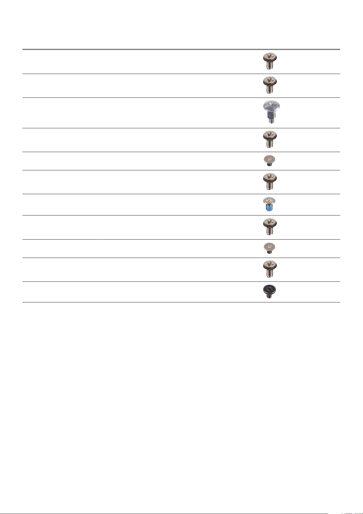
Table 1. Wyse 5470 All-in-One
Component Screw type Quantity Screw image
Cable cover M3x9 1
System board shield M3x5 5
2
Solid-state drive/Intel Optane
card
WLAN card shield M2x2.5 2
WLAN card M2x2.5 1
System fan M3 x5 3
Pop-up camera assembly M3x5 2
Pop-up camera bezel M3x5 5
Base cover M3x5 4
PSU cable M3x5 1
Power supply unit—PSU M3x5 1
M2x2.5 1
Power supply unit fan—PSU fan M3x5 2
Removing and installing components 9
Page 10
Component Screw type Quantity Screw image
Input and Output bracket M3x5 3
System board M3x5 9
Speakers M3 4+7.1 XZN 4
Power button board M3x5 1
Microphone M2x2.5 2
Input and Output board shield M3x5 2
Input and Output board M2.5x3.5 2
Headset port M3x5 1
Antennas M2x2.5 2
Display panel M3x5 8
Middle frame M3x5 11
Stand
Removing the easel stand
Prerequisites
Follow the procedure in Before working on your thin client.
About this task
The following image indicates the location of the stand and provides a visual representation of the removal procedure.
Removing and installing components
10
Page 11

Removing and installing components 11
Page 12
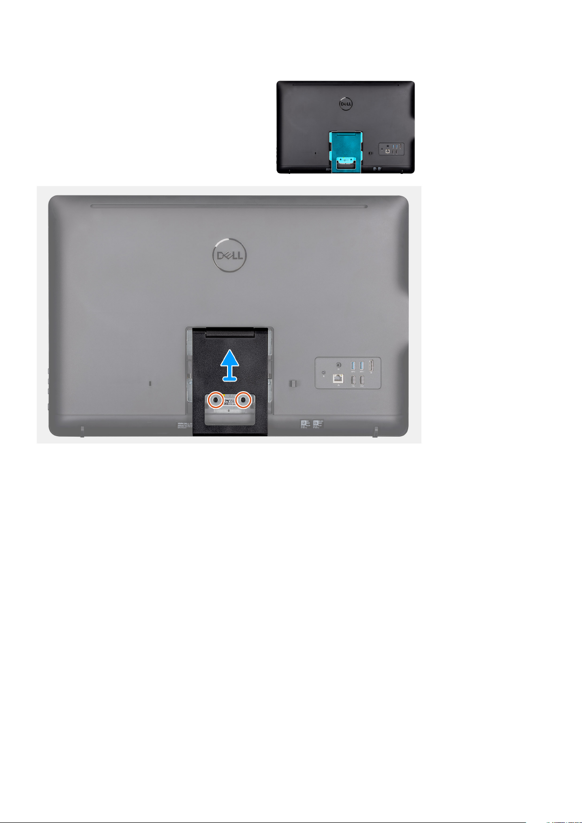
Steps
1. Pry up the stand cover off the back cover using a plastic scribe.
2. Slide and remove the stand cover from the back cover.
3. Remove the two screws (M4x8) that secure the easel stand to the stand bracket and lift the stand off the back cover.
Installing the easel stand
Prerequisites
If you are replacing a component, remove the existing component before performing the installation procedure.
About this task
The following image indicates the location of the easel stand and provides a visual representation of the installation procedure.
Removing and installing components
12
Page 13

Removing and installing components 13
Page 14
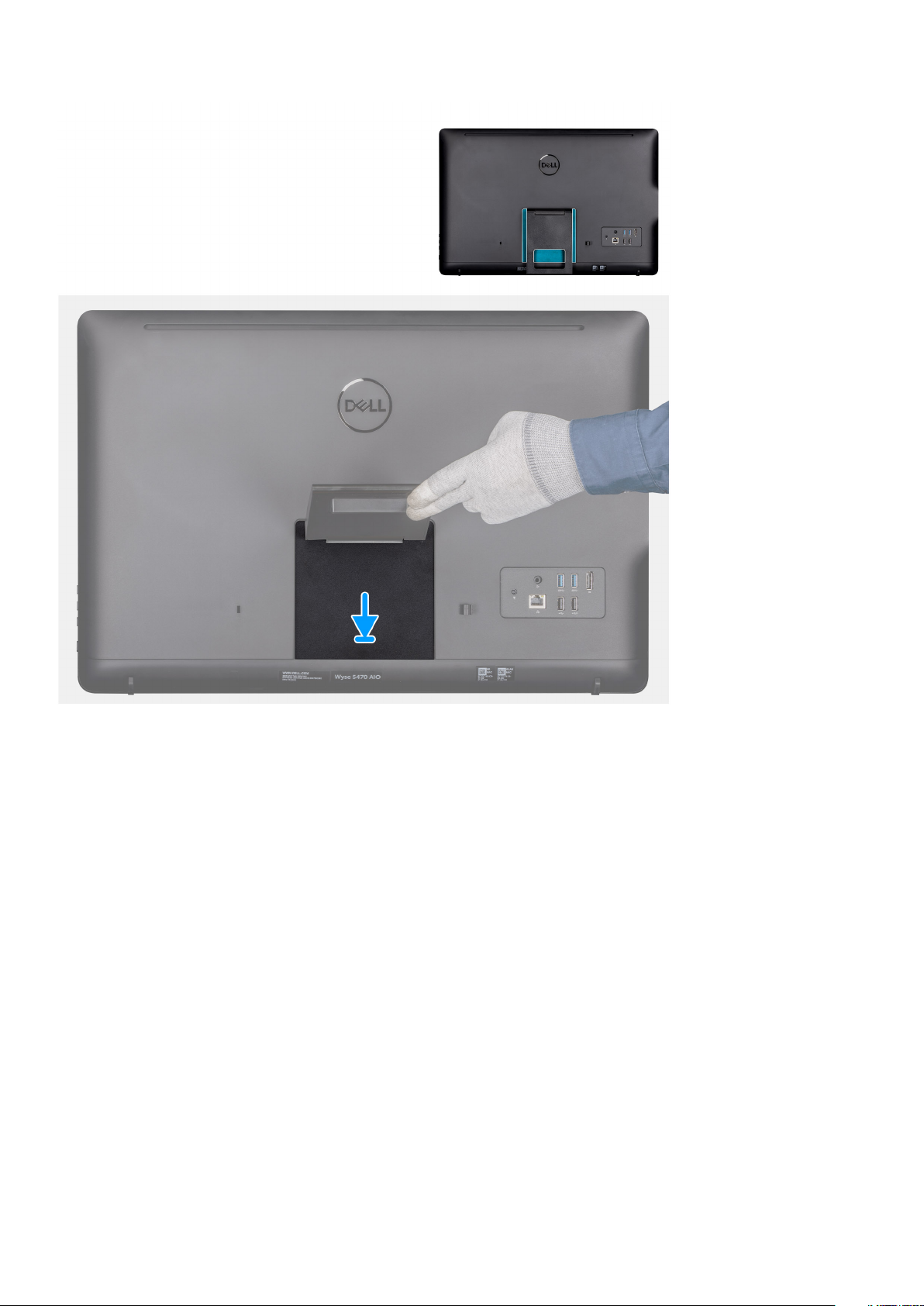
Steps
1. Align the screw holes on the stand bracket to the screw holes on the easel stand.
2. Tighten the two screws (M4x8) that secure the easel stand to the chassis.
3. Slide and place the stand cover on the stand bracket.
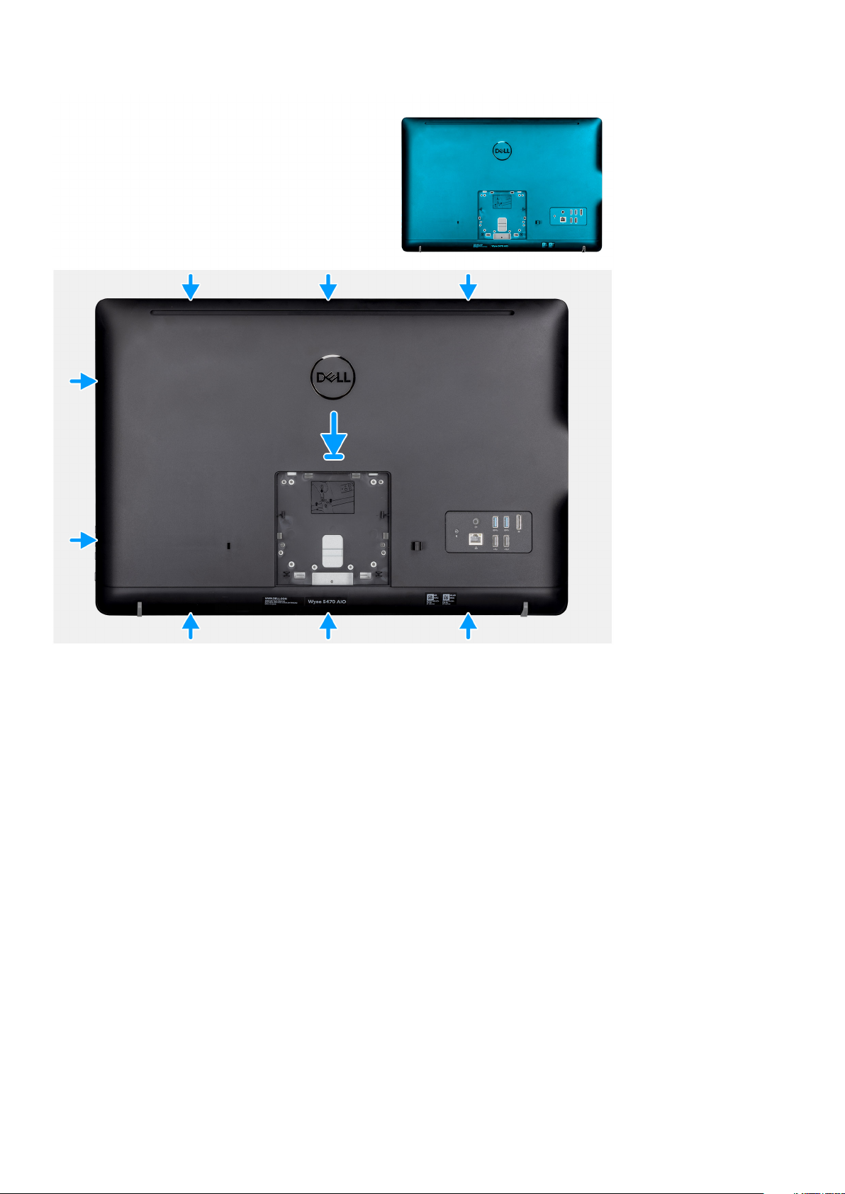
Back cover
Removing the back cover
Prerequisites
1. Follow the procedure in Before working on your thin client.
2. Remove the stand.
About this task
The following image indicates the location of the back cover and provides a visual representation of the removal procedure.
Removing and installing components
14
Page 15

Steps
1. Using a scribe, pry the back cover from the chassis.
2. Ensure all the notches are unlocked using the scribe around the thin client.
3. Lift the back cover away from the chassis of the thin client.
Installing the back cover
Prerequisites
If you are replacing a component, remove the existing component before performing the installation procedure.
About this task
The following image indicates the location of the back cover and provides a visual representation of the installation procedure:
Removing and installing components
15
Page 16
Steps
1. Place the back cover on to the system chassis.
2. Align the notches on the back cover with the slots on the chassis.
3. Press the back cover to the system chassis and ensure all the locks are secured in position.
Next steps
1. Install the stand.
2. Follow the procedure in After working on your thin client.
Vesa-mount bracket
Removing the VESA-mount bracket
Prerequisites
1. Follow the procedure in Before working on your thin client.
2. Remove the stand.
3. Remove the back cover.
About this task
The following image indicates the location of VESA-mount bracket and provides a visual representation of the removal procedure.
Removing and installing components
16
Page 17
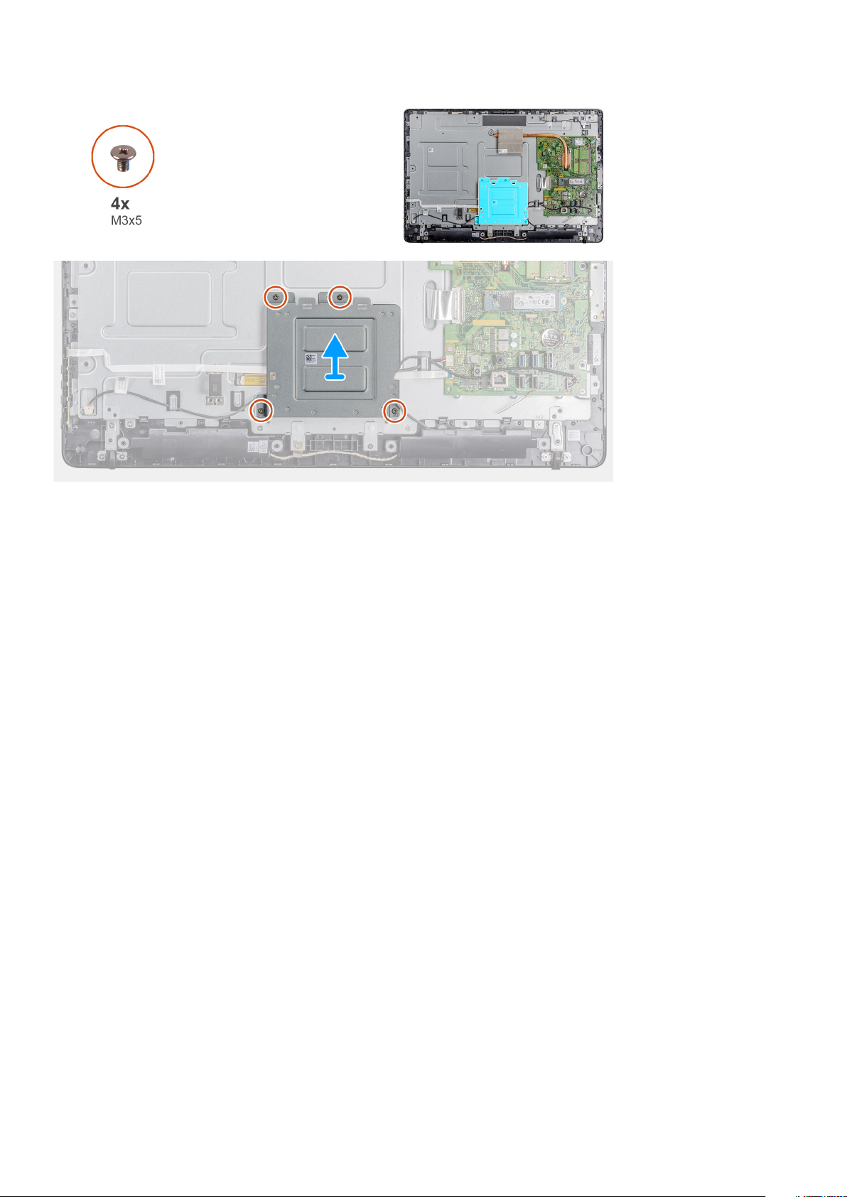
Steps
1. Remove the four screws (M3x5) that secure the VESA-mount bracket to the middle cover.
2. Lift the VESA-mount bracket off the middle cover.
3. Note the speaker cable routing on the VESA-mount bracket and remove it from the routing guides.
Installing the VESA-mount bracket
Prerequisites
If you are replacing a component, remove the existing component before performing the installation procedure.
About this task
The following image indicates the location of the VESA-mount bracket and provides a visual representation of the installation procedure.
Removing and installing components
17
Page 18

Steps
1. Align the screw holes on the VESA-mount bracket with the screw holes on the middle frame.
2. Replace the four screws (M3x5) that secure the vesa-mount bracket to the middle frame.
3. Route the speaker cable through the routing guides on the VESA-mount bracket.
Next steps
1. Install the back cover.
2. Install the stand.
3. Follow the procedure in After working on your thin client.
On-screen display board
Removing the OSD board
Prerequisites
1. Follow the procedure in Before working on your thin client.
2. Remove the stand.
3. Remove the back cover.
4. Remove the VESA-mount bracket.
About this task
The following image indicates the location of OSD board and provides a visual representation of the removal procedure.
Removing and installing components
18
Page 19

Steps
1. Open the latch and disconnect the cable from the system board.
2. Peel off the OSD cable from the middle frame.
3. Move the securing clip away from the control-buttons board and lift the OSD board out of the slot.
Installing the OSD board
Prerequisites
If you are replacing a component, remove the existing component before performing the installation procedure.
About this task
The following image indicates the location of the OSD board and provides a visual representation of the installation procedure.
Removing and installing components
19
Page 20

Steps
1. Move the securing clip away and place the OSD board until it locks in to the display bezel.
2. Adhere the tape that secures the OSD board cable to the middle frame.
3. Connect the cable to the connector on the system board.
4. Close the latch to secure the cable.
Next steps
1. Install the vesa-mount bracket.
2. Install the back cover.
3. Install the stand.
4. Follow the procedure in After working on your thin client.
Solid-state drive
Removing the solid-state drive
Prerequisites
1. Follow the procedure in Before working inside your thin client.
2. Remove the stand.
3. Remove the back cover.
About this task
The following image indicates the location of the solid-state drive and provides a visual representation of the removal procedure.
Removing and installing components
20
Page 21

Steps
1. Remove the screw (M2x3.5) that secures the solid-state drive card to the system board.
2. Slide and remove the solid-state drive off the solid-state drive slot on the system board.
Installing the solid-state drive
Prerequisites
If you are replacing a component, remove the existing component before performing the installation procedure.
About this task
The following image indicates the location of the solid-state drive and provides a visual representation of the installation procedure.
Removing and installing components
21
Page 22

Steps
1. Align the notch on the solid-state drive with the tab on the solid-state drive slot and slide the solid-state drive into the solid-state drive
slot on the system board.
2. Replace the screw (M2x3.5) that secures the solid-state drive to the system board.
Next steps
1. Install the back cover.
2. Install the stand.
3. Follow the procedure in After working inside your thin client.
Memory module
Removing the memory modules
Prerequisites
1. Follow the procedure in Before working on your thin client.
2. Remove the stand.
3. Remove the back cover.
About this task
The following image indicates the location of the memory modules and provides a visual representation of the removal procedure.
Removing and installing components
22
Page 23

Steps
1. Using your fingertips, carefully spread apart the securing clips at each end of the memory-module slot until the memory module pops
up.
2. Slide and remove the memory module from the memory-module slot.
Installing the memory modules
Prerequisites
If you are replacing a component, remove the existing component before performing the installation procedure.
About this task
The following image indicates the location of the memory modules and provides a visual representation of the installation procedure.
Removing and installing components
23
Page 24

Steps
1. Align the notch on the memory module with the tab on the memory-module slot.
2. Slide the memory module firmly into the slot at an angle and press the memory module down until it clicks into place.
Next steps
1. Install the back cover.
2. Install the stand.
3. Follow the procedure in After working on your thin client.
Wireless card
Removing the wireless card
Prerequisites
1. Follow the procedure in Before working on your thin client.
2. Remove the stand.
3. Remove the back cover.
About this task
The following image indicates the location of wireless card and provides a visual representation of the removal procedure:
Removing and installing components
24
Page 25

Steps
1. Remove the screw (M2x3.5) that secures the wireless-card bracket and the wireless card to the system board.
2. Slide the wireless-card bracket off the wireless card.
3. Disconnect the antenna cables from the wireless card.
4. Slide the wireless card out of the wireless card slot.
Installing the wireless card
Prerequisites
If you are replacing a component, remove the existing component before performing the installation procedure.
About this task
The following image indicates the location of the wireless card and provides a visual representation of the installation procedure:
Removing and installing components
25
Page 26

Steps
1. Align the notch on the wireless card with the tab on the wireless-card slot and slide the card into the slot.
2. Connect the antenna cables to the wireless card.
3. Slide the wireless-card bracket over the wireless card.
4. Align the screw hole on the wireless-card bracket with the screw hole on the wireless card.
5. Replace the screw (M2x3.5) that secures the wireless-card bracket and the wireless card to the system board.
Next steps
1. Replace the back cover.
2. Replace the stand.
3. Follow the procedure in After working on your thin client.
Heat sink
Removing the heat sink
Prerequisites
1. Follow the procedure in Before working on your thin client.
2. Remove the stand.
3. Remove the back cover.
About this task
The following image indicates the location of wireless card and provides a visual representation of the removal procedure.
NOTE:
assembly may differ.
26 Removing and installing components
Depending on the configuration you ordered, the number of screws and the appearance of the heat-sink
Page 27

Steps
1. In sequential order (as indicated on the heat sink), loosen the four captive screws (M3x7) that secure the heat sink to the system
board.
2. Lift the heat sink off the system board.
Installing the heat sink
Prerequisites
If you are replacing a component, remove the existing component before performing the installation procedure.
About this task
The following image indicates the location of the heat sink and provides a visual representation of the installation procedure.
Removing and installing components
27
Page 28

Steps
1. Align the captive screws on the heat sink with the screw holes on the system board.
2. In sequential order (as indicated on the heat sink), tighten the four captive screws (M3x7) that secure the heat sink to the system
board.
Next steps
1. Replace the back cover.
2. Replace the stand.
3. Follow the procedure in After working on your thin client.
Coin-cell battery
Removing the coin-cell battery
Prerequisites
1. Follow the procedure in Before working on your thin client.
2. Remove the stand.
3. Remove the back cover.
About this task
The following image indicates the location of coin-cell battery and provides a visual representation of the removal procedure.
Removing and installing components
28
Page 29

Steps
1. Pry open the coin-cell battery using a scribe.
2. Remove the coin-cell battery from the holder.
Installing the coin-cell battery
Prerequisites
If you are replacing a component, remove the existing component before performing the installation procedure.
About this task
The following image indicates the location of the coin-cell battery and provides a visual representation of the installation procedure:
Removing and installing components
29
Page 30

Steps
Place the coin-cell battery in the holder and press until it snaps in to the place.
Next steps
1. Install the back cover.
2. Install the stand.
3. Follow the procedure in After working on your thin client.
Camera
Removing the camera
Prerequisites
1. Follow the procedure in Before working on your thin client.
2. Remove the stand.
3. Remove the back cover.
About this task
The following image indicates the location of the camera and provides a visual representation of the removal procedure.
Removing and installing components
30
Page 31

Steps
1. Note the antenna, microphone, and camera-cable routing and remove the cables from the routing guides on the display bezel and
middle cover.
2. Using your fingertips, press the securing clip and lift the camera assembly.
3. Disconnect the camera cable from the camera.
4. Disconnect the camera assembly from the tab on the display bezel.
Installing the camera
Prerequisites
If you are replacing a component, remove the existing component before performing the installation procedure.
About this task
The following image indicates the location of the camera and provides a visual representation of the installation procedure:
Removing and installing components
31
Page 32

Steps
1. Connect the camera cable to the connector port on the system board.
2. Connect the camera assembly to the tabs on the display bezel.
3. Press the camera assembly into the slot on the display bezel until the securing clip locks in place.
4. Route the camera cable through the routing guides on the middle frame and display bezel.
Next steps
1. Install the back cover.
2. Install the stand.
3. Follow the procedure in After working on your thin client.
System board
Removing the system board
Prerequisites
1. Follow the procedure in Before working inside your thin client.
2. Remove the stand.
3. Remove the back cover.
4. Remove the Vesa mount.
5. Remove the memory module
6. Remove the Solid state drive.
7. Remove the WLAN card.
8. Remove the heat sink.
About this task
The following image indicates the location of system board and provides a visual representation of the removal procedure:
Removing and installing components
32
Page 33

Steps
1. Disconnect the camera cable, speaker cable, OSD board cable, and converter cable from the system board.
2. Remove the heat sink from the system board.
3. Peel the tape from the middle frame that secures the OSD board cable to the system board.
4. Using the pull tab, disconnect the display cable from the system board.
5. Remove the memory module from the memory module slot on the system board.
6. Remove the WLAN card from the WLAN card slot on the system board.
7. Remove the four screws (M3x5) that secure the system board to the middle frame.
8. Gently lift and move the system board towards the left to free the system board away from the USB / global headset jack port frame
on the middle frame chassis.
Installing the system board
Prerequisites
If you are replacing a component, remove the existing component before performing the installation procedure.
About this task
The following image indicates the location of system board and provides a visual representation of the installation procedure.
Removing and installing components
33
Page 34

Steps
1. Slide the system board into the slots on to the middle frame.
2. Align the screw holes on the system board with the screw holes on the chassis.
3. Replace the four screws (M3x5) on to the system board.
4. Install the heat sink assembly to the system board.
5. Connect the converter board cable securely to the system board.
6. Connect the on-screen display cable to the system board and close the latch to secure it.
7. Connect the camera cable securely to the system board.
8. Connect the display cable (LVDS) and secure the connection to the system board.
9. Connect the speaker cable to the system board.
Next steps
1. Install the heat sink.
2. Install the WLAN card.
3. Install the Solid-state drive.
4. Install the memory module.
5. Install the Vesa-mount.
6. Install the back cover.
7. Install the stand.
Removing and installing components
34
Page 35

Speakers
Removing the speakers
Prerequisites
1. Follow the procedure in Before working on your thin client.
2. Remove the stand.
3. Remove the back cover.
About this task
The following image indicates the location of speakers and provides a visual representation of the removal procedure:
Steps
1. Disconnect the speaker cable from the system board.
2. Remove the speaker cable from the routing guide on the VESA-mount bracket.
3. Note the speaker-cable routing on the display bezel and remove the screw (M3x5) that secures the cable to the middle frame.
4. Peel off the tape from the VESA-mount bracket.
5. Lift the speakers, along with the speaker cable, off the display assembly.
Installing the speakers
Prerequisites
If you are replacing a component, remove the existing component before performing the installation procedure.
About this task
The following image indicates the location of the speakers and provides a visual representation of the installation procedure.
Removing and installing components
35
Page 36

Steps
1. Using the alignment posts, place the speakers on the display assembly.
2. Route the speaker cable through the routing guide on the display bezel.
3. Adhere the tape of the speaker cable to the VESA-mount bracket and the routing guide.
4. Connect the speaker cable to the system board.
Next steps
1. Replace the back cover.
2. Replace the stand.
3. Follow the procedure in After working on your thin client.
Middle frame
Removing the middle frame
Prerequisites
1. Follow the procedure in Before working on your thin client.
2. Remove the stand.
3. Remove the back cover.
4. Remove the VESA-mount.
5. Remove the Solid state drive.
6. Remove the wireless card.
7. Remove the heat sink.
8. Remove the systemboard.
9. Remove the OSD board.
10. Remove the speaker.
About this task
The following image indicates the location of the middle frame and provides a visual representation of the removal procedure:
Removing and installing components
36
Page 37

Steps
1. Note the routing of the antenna, camera, and microphone cables and remove the cables from the routing guides on the middle frame.
2. Disconnect the converter board cable from the display panel and remove it off the middle frame.
3. Remove the eight screws (M3x3) that secure the middle frame to the display panel.
4. Remove the eighteen screws (M3x5) that secure the middle frame to the chassis.
5. Release the middle cover from the tabs on the display assembly.
6. Slide the display cable through the slot on the display assembly.
7. Lift the middle frame off the chassis.
Installing the middle frame
Prerequisites
If you are replacing a component, remove the existing component before performing the installation procedure.
About this task
The following image indicates the location of the middle frame and provides a visual representation of the installation procedure:
Removing and installing components
37
Page 38

Steps
1. Align the slots on the middle frame with the slots on the chassis.
2. Slide the display cable through the slot on the middle frame.
3. Place the middle frame on the display assembly and press down until the tabs lock in place.
4. Replace the eighteen screws (M3x5) that secure the middle frame to the chassis.
5. Replace the eight screws (M3x3) that secure the middle frame to the display panel.
6. Connect the converter board cable to the display panel and route the cable on to the middle frame.
7. Route of the antenna, camera, and microphone cables on to the routing guides on the middle frame.
Next steps
1. Install the speaker.
2. Install the VESA-mount.
3. Install the system board.
4. Install the heat sink.
5. Install the wireless card.
6. Install the solid state drive.
7. Install the OSD board.
8. Install the back cover.
9. Install the stand.
10. Follow the procedure in After working on your thin client.
Removing and installing components
38
Page 39

Rubber feet
Removing the rubber feet
Prerequisites
1. Follow the procedure in Before working on your thin client.
2. Remove the stand.
3. Remove the back cover.
4. Remove the VESA-mount.
5. Remove the solid-state drive.
6. Remove the wireless card.
7. Remove the heat sink.
8. Remove the system board.
9. Remove the speakers.
10. Remove the middle frame.
About this task
The following image indicates the location of rubber feet and provides a visual representation of the removal procedure:
Steps
1. Remove the two screws (M3x5) that secure the rubber foot to the display assembly.
2. Lift the rubber foot off the display bezel.
Installing the rubber feet
Prerequisites
If you are replacing a component, remove the existing component before performing the installation procedure.
Removing and installing components
39
Page 40

About this task
The following image indicates the location of the rubber feet and provides a visual representation of the installation procedure:
Steps
1. Align the screw holes on the rubber foot with the screw holes on the display bezel.
2. Install the two screws (M3x5) that secure the rubber foot to the display assembly.
Next steps
1. Install the middle cover.
2. Install the speakers.
3. Install the VESA-mount.
4. Install the system board.
5. Install the heat sink.
6. Install the wireless card.
7. Install the heat sink.
8. Install the solid-state drive.
9. Install the back cover.
10. Install the stand.
11. Follow the procedure in After working on your thin client.
Display panel
Removing the display panel
Prerequisites
1. Follow the procedure in Before working on your thin client.
2. Remove the stand.
3. Remove the back cover.
4. Remove the Vesa-mount.
5. Remove the speakers.
Removing and installing components
40
Page 41

6. Remove the on-screen display board.
7. Remove the camera.
8. Remove the WLAN card.
9. Remove the memory module.
10. Remove the solid-state drive.
11. Remove the heat sink.
12. Remove the middle frame.
About this task
The following image indicates the location of display panel and provides a visual representation of the removal procedure.
Steps
After performing the preceding steps, you are left with the display panel assembly.
Installing the display panel
Prerequisites
If you are replacing a component, remove the existing component before performing the installation procedure.
Removing and installing components
41
Page 42

About this task
The following image indicates the location of display panel and provides a visual representation of the installation procedure.
Steps
Place the display panel assembly on a flat surface.
Next steps
1. Install the middle frame.
2. Install the camera.
3. Install the speakers
4. Install the system board.
5. Install the heat sink.
6. Install the WLAN card.
7. Install the memory module.
8. Install the Vesa-mount.
9. Install the back cover.
10. Install the stand.
11. Follow the procedure in After working on your thin client.
42
Removing and installing components
Page 43

3
System setup
System Setup overview
System Setup allows you to:
• Change the system configuration information after you add, change, or remove any hardware in your thin client.
• Set or change a user-selectable option such as the user password.
• Read the current amount of memory or set the type of hard drive installed.
Before you use System Setup, Dell recommends that you write down the System Setup screen information for future reference.
CAUTION: Unless you are an expert thin client user, do not change the settings for this program. Certain changes can
cause your thin client to work incorrectly.
Accessing thin client BIOS settings
About this task
This section describes about the Wyse 5470 AIO UEFI BIOS settings. While starting a thin client, a Dell logo is displayed for a short period.
Steps
1. During start-up, press the F2 key. and enter the default password Fireport.
The BIOS settings dialog box is displayed.
2. Use the System Setup settings to change the BIOS settings.
NOTE:
menu. BIOS default setting restores the values that was part of the BIOS file. Restoring Factory default restores the
BIOS setting to the values that was configured in factory before shipping the client.
Next steps
To access the boot menu during start-up, press the F12 key. Use the Boot Selection menu to select or view the boot sequence order as
follows:
• Boot from UEFI: Hard Drive, Partition 4
There is an option to restore BIOS defaults, Factory Defaults, and Custom user settings for Users in the BIOS
Navigation keys
NOTE:
restart the system.
Table 2. Navigation keys
Keys Navigation
Up arrow Moves to the previous field.
For most of the System Setup options, changes that you make are recorded but do not take effect until you
Down arrow Moves to the next field.
Enter Selects a value in the selected field (if applicable) or follow the link in the field.
Spacebar Expands or collapses a drop‐down list, if applicable.
Tab Moves to the next focus area.
NOTE: This option is applicable for the standard graphics browser only.
System setup 43
Page 44

Keys Navigation
Esc Moves to the previous page until you view the main screen. Pressing Esc in the main screen displays a
message that prompts you to save any unsaved changes and restarts the system.
Boot Sequence
Boot Sequence enables you to bypass the System Setup defined boot device order and boot directly to a specific device. During the
Power-on Self-Test (POST), when the Dell logo is displayed you can:
• Access System Setup by pressing the F2 key
• Bring up the one-time boot menu by pressing the F12 key
The one-time boot menu displays the devices that you can boot from including the diagnostic option. The boot menu options are:
• UEFI Boot
• UEFI: Windows Boot Manager
• UEFI: Hard drive, Partition 4
• Other options
• BIOS Setup
• BIOS Flash Update
• Diagnostics
• Exit Boot Menu and Continue
NOTE: If you select the Diagnostics option, the ePSA diagnostics screen is displayed. To access the System setup
menu, click BIOS Setup.
General screen options
This section lists the primary hardware features of your thin client.
Table 3. General screen options
Option Description
System Information This section lists the primary hardware features of your thin client.
• System Information: Displays BIOS Version, Service Tag, Asset
Tag, Ownership Tag, Ownership Date, Manufacture Date,
Express Service Code, the Signed Firmware update—enabled
by default
• Memory Information: Displays Memory Installed, Memory
Available, Memory Speed, Memory Channels Mode, Memory
Technology, DIMM A Size, DIMM B Size
NOTE: Since Memory Available is less than the
Memory Installed, certain operating systems may not
be able to use all the available memory.
• PCI information: Displays Slot details, by default Slot1 is empty.
• Processor Information: Displays Processor Type, Core Count,
Processor ID, Current Clock Speed, Minimum Clock Speed,
Maximum Clock Speed, Processor L2 Cache, Processor L3
Cache, HT Capable, and 64-Bit Technology
• Device Information: Primary Hard Drive, Video Controller, Audio
Controller, Wi-Fi Device, Bluetooth Device
44 System setup
Page 45

Option Description
Boot Sequence This option enables you to change the order in which the system
boots an operating system.
• Default Boot Sequence
• Windows Boot Manager
• UEFI: Hard Drive, Partition 4
• Boot List Option: You can add a boot option, delete an existing
boot option, and view the boot options.
UEFI boot path security
Date/Time This option enables you to change the system date and time.
This option enables you to control the system prompt of How to
enter the Admin Password (if set) when you boot a UEFI boot
path from the F12 boot menu.
The options include:
• Always, except internal hard drive (default)
• Always
• Never
System Configuration screen options
Table 4. System Configuration options
Option Description
UEFI Network Stack If the UEFI Network Stack option is enabled, the UEFI
Networking Protocols are installed and allows pre-operating system
and early operating system networking features to use any enabled
NICs or SFP.
The UEFI Network Stack option is enabled by default.
Integrated NIC The Integrated NIC option controls the on-board LAN controller.
The options include:
• Disabled—The internal LAN is off and not visible to the
operating system.
• Enabled—The internal LAN is enabled.
• Enabled w/PXE—The internal LAN is enabled (with PXE boot).
This option is enabled by default.
SATA Operation This option configures the operating mode of the integrated SATA
hard drive controller. The options include:
• Disabled
• AHCI—enabled by default
Drives Allows you to configure the SATA drive on board and the M.2 PCIe
SSD.
• SATA-0 enabled by default
• M.2 PCIe SSD-0
SMART Reporting This field controls whether the hard drive errors of integrated
drives are reported during system startup.
System setup 45
Page 46

Option Description
USB Configuration
Side USB Configuration This option enables or disables side USB ports. The options include:
Rear USB Configuration This option enables or disables rear USB ports. The options are:
This is an optional feature.
This field configures the integrated USB controller. If Boot Support
is enabled, the system is allowed to boot any type of USB Mass
Storage Devices such as hard drives and USB keys.
If the USB port is enabled, the device attached to this port is
enabled and available for the operating system.
If the USB port is disabled, the operating system cannot detect any
device attached to this port.
The options include:
• Enable USB Boot Support—enabled by default
• Enable Side USB Ports—enabled by default
• Enable Rear USB Ports—enabled by default
NOTE: USB keyboard and mouse always work in the
BIOS setup irrespective of these settings.
• Side port Top—enabled by default
• Side port Bottom —enabled by default
• Rear port Top Left—enabled by default
• Rear port Bottom Left—enabled by default
• Rear port Top Right—enabled by default
• Rear port Bottom Right—enabled by default
USB PowerShare This option configures the USB PowerShare feature and allows you
to charge external devices through the USB PowerShare port
when system is off. This option is enabled by default.
Audio This option enables or disables the integrated audio controller. By
default, the Enable Audio option is selected. The options include:
• Enable Microphone—enabled by default
• Enable Internal Speaker—enabled by default
OSD Button Management This option allows the user to disable the OSD (On-Screen Display)
buttons on the system. This option is disabled by default.
Miscellaneous devices This option enables or disables the camera of the Thin Client. By
default, the Enable Camera option is selected.
Video screen option
Table 5. Video screen option
Option Description
Primary Display This option determines which video controller is the primary display
when multiple controllers are available in the system. The options
include:
• Auto—enabled by default
• Intel HD Graphics
46 System setup
Page 47

Security screen options
Table 6. Security screen options
Option Description
Admin Password This option enables you to set, change, or delete the administrator
password.
NOTE:
• You must set the administrator password before you
set the system or hard drive password. Also, deleting
the administrator password automatically deletes the
system password and the hard drive password.
• Successful password changes take effect
immediately.
By default, the administrator password is not set.
System Password This option enables you to set, change, or delete the system
password.
NOTE: Successful password changes take effect
immediately.
By default, the administrator password is not set.
Internal HDD-0 password This option enables you to set, change, or delete the internal hard
drive (HDD-0) password.
• When a hard drive password is set, it travels with the hard
drive, so the hard drive is protected even if it is installed on
another system.
• The user will be prompted to enter the password every time
the user tries to access the hard drive. If the correct password
is not entered the hard drive will not function.
• By default, the hard drive will not have a password set.
Strong Password This option enables you to enforce the option to always set strong
passwords.
By default, the Enable Strong Password option is not selected.
NOTE: If Strong Password is enabled, the administrator
and system passwords must contain at least one
uppercase character and one lowercase character. The
password must be at least eight characters long.
Password Configuration This option enables you to specify the minimum and maximum
password lengths of the administrator and system passwords.
• min-4—By default, the minimum value is set to 4. You can
increase the value.
• max-32—By default, the maximum value is set to 32. You can
decrease the value.
Password Bypass This option enables you to enable and disable the permission to
bypass the system and the internal hard drive password, when they
are set. The options are:
• Disabled—enabled by default
• Reboot Bypass
System setup 47
Page 48

Option Description
Password Change This option enables you to enable the disable permission to the
system and hard drive passwords when the administrator password
is set.
By default, the Allow Non-Admin Password Changes option is
selected.
UEFI Capsule Firmware Updates This option enables you to enable or disable UEFI Capsule
Firmware. This option controls whether this system enables BIOS
update through UEFI capsule update packages. This option is
enabled by default.
TPM 2.0 Security This option enables you to enable the Trusted Platform Module
Technology feature. The options include:
• TPM On—enabled by default
• Clear
• PPI Bypass for Enable Commands
• Attestation Enable—enabled by default
• PPI Bypass for Disable Commands
• Key Storage Enable—enabled by default
• PPI Bypass for Clear Command
• SHA-256—enabled by default
• Disabled
• Enabled—selected by default
Admin Setup Lockout This option enables you to prevent users from entering Setup when
an administrator password is set.
Master Password Lockout This is an authentication information that is sometimes required to
log into a thin client's basic input/output system (BIOS) before the
machine boots up to the operating system. The Hard disk
passwords needs to be cleared before enabling the Master
Password Lockout. This option will be disabled by default.
SMM Security Mitigation This option enables you to enable and disable additional UEFI SMM
security mitigation protections.
Secure Boot screen options
Table 7. Secure Boot screen options
Options Description
Secure Boot Enable This option enables or disables the secure boot feature. By default,
the Secure Boot Enable option is not set.
Secure Boot Mode This option enables you to change the secure boot operation mode,
modifies the behavior of secure boot to allow evaluation or
enforcement of the UEFI driver signatures. The options include:
• Deployed Mode
• Audit Mode
48 System setup
Page 49

Options Description
Expert Key Management This option enables you to manipulate the security key databases
only if the system is in Custom Mode. The Enable Custom Mode
option is disabled by default. The options include:
• PK
• KEK
• db
• dbx
If you enable the Custom Mode, the relevant options for PK, KEK,
db, and dbx is displayed. The options are:
• Save to File—Saves the key to a user-selected file
• Replace from File—Replaces the current key with a key from a
user-selected file
• Append from File—Adds a key to the current database from a
user-selected file
• Delete—Deletes the selected key
• Reset All Keys—To reset the default setting
• Delete All Keys—Deletes all the keys
NOTE: If you disable the Custom Mode, all the changes
are erased and the keys are restored to the default
settings.
Intel Software Guard Extensions screen options
Table 8. Intel Software Guard Extensions options
Option Description
Intel SGX Enable Enable Intel Software Guard Extensions option to provide a secured
environment for running code or storing sensitive information with
respect to the operating system. The options are:
• Disabled
• Enabled
• Software Controlled—This option is enabled by default
Enclave Memory Size This option sets the Intel Software Guard Extensions (SGX)
Enclave Reserve Memory size. When SGX is set to Software
Controlled, this setting is not available and has no effect. The
options include:
• 32 MB
• 64 MB
• 128 MB—default
Performance screen options
Table 9. Performance options
Option Description
Multi Core Support This option specifies whether one or more cores are enabled on the
processor. The options include:
• All—enabled by default
• 1
• 2
• 3
System setup 49
Page 50

Option Description
Intel SpeedStep This option enables you to enables or disables the Intel SpeedStep
feature. The option is:
Enable Intel SpeedStep
This option is enabled by default.
C-States Control This option enables you to enables or disables the additional
processor sleep states.
This option is disabled by default.
Intel TurboBoost This option enables you to enables or disables the Intel TurboBoost
mode of the processor. The option is:
Enable Intel TurboBoost—This option is enabled by default.
Power management screen options
Table 10. Power management options
Option Description
AC Recovery This option enables you to control the system’s behavior when AC
power is restored after a AC power loss.
• Power Off—enabled by default
• Power On
• Last Power State
Auto On Time This option enables you to set the time at which the computer
must turn on automatically. The options include:
• Disabled—enabled by default
• Every Day
• Weekdays
• Select Days
Deep Sleep Control This option enables you to determine on how aggressive the
system is at conserving power while shutdown—S5 or in Hibernate
(S4) mode. The options include:
• Disabled—This option enabled by default
• Enabled in S5 only
• Enabled in S4 and S5
USB Wake Support This option enables USB devices to wake the system from standby.
NOTE: This feature is only functional when the AC power
adapter is connected. If the AC power adapter is
removed during standby, the system setup removes
power from all the USB ports to conserve battery power.
The Enable USB Wake Support option is enabled by default.
Wake on LAN This option enables or disables the feature that powers on the
computer from the Off state when triggered by a LAN signal. The
options include:
• Disabled
• LAN Only—This option is enabled by default.
• LAN with PXE Boot
50 System setup
Page 51

Option Description
Block Sleep The Block Sleep option blocks you from entering to sleep mode in
the operating system environment.
Block Sleep—This option is disabled by default.
POST behavior screen options
Table 11. POST behavior options
Option Description
Adapter Warnings This option enables or disables the system setup (BIOS) warning
messages when you use certain power adapters.
By default, the Enable Adapter Warnings option is enabled.
Numlock LED This option enables and disables the Numlock LED when the
system boots.
By default, this option is enabled.
Keyboard Error This option enables you to specify whether keyboard related errors
are reported when the system boots. By default, the Enable
Keyboard Error Detection option is enabled
Fastboot This option enables you to speed up the boot process by bypassing
some of the compatibility steps. The options include:
• Minimal
• Thorough—This option is enabled by default.
• Auto
Extended BIOS POST Time This option enables you to create an extra preboot delay. The
options include:
• 0 seconds—This option is enabled by default.
• 5 seconds
• 10 seconds
Full Screen Logo This option enables or disables the full screen logo. By default, the
Enable Full Screen Logo option is not enabled.
Wireless screen option
Table 12. Wireless option
Option Description
Wireless Device Enable This options enables or disables the internal wireless devices. The
options include:
• WLAN/BT — enabled by default
Virtualization support screen options
Table 13. Virtualization options
Option Description
Virtualization This option enables or disables the Intel Virtualization Technology.
Enable Intel Virtualization Technology (default).
System setup 51
Page 52

Option Description
VT for Direct I/O This option specifies whether a virtual machine monitor can utilize
the additional hardware capabilities provided by Intel Virtualization
Technology for Direct I/O. This option is not enabled by default.
Maintenance screen options
Table 14. Maintenance options
Option Description
Service Tag Displays the Service Tag of your computer.
Asset Tag This option enables you to create a system asset tag if an asset tag
is not already set. This option is not set by default.
SERR Messages This option enables you to control the SERR message mechanism.
The Enable SERR Message option is enabled by default.
BIOS Downgrade This controls flashing of the system firmware to previous revisions.
The option Allow BIOS downgrade is enabled by default.
Data Wipe This field enables you to erase the data securely from all internal
storage devices. Option Wipe on Next boot is not enabled by
default. The following is the list of devices affected:
• Internal SATA HDD/SSD
• Internal M.2 SATA SDD
• Internal M.2 PCIe SSD
• Internal eMMC
CAUTION: All the information will be lost if you enable
this option.
BIOS Recovery This option enables you to recover certain corrupted BIOS
conditions from a recover file on the user’s primary hard drive or an
external USB key.
• BIOS Recovery from Hard Drive—enabled by default
• BIOS Auto-Recovery—disabled by default
System Logs screen option
Table 15. System Logs screen option
Option Description
BIOS Events This option enables you to delete all the logs.
Advanced configurations
Table 16. Advanced configurations
Option Description
Active State Power Management (ASPM) ASPM is a power management mechanism for PCI Express devices
to garner power savings while otherwise in a fully active state. The
options include:
• Auto — Communicattion between device and PCI Express hub.
• Disabled — ASPM turned off at all times.
• L1 Only — ASPM is set to use L1.
52 System setup
Page 53

4
Troubleshooting your system
You can troubleshoot the thin client by using indicators such as diagnostic lights and error messages during the operation of the device.
Additionally, you can use Enhanced Pre-Boot System Assessment (ePSA) diagnostics to carry out complete diagnosis and troubleshooting
of thin clients.
Topics:
• Enhanced Pre-Boot System Assessment diagnostics
• Power behavior
• Power state and LED status
Enhanced Pre-Boot System Assessment diagnostics
About this task
The Enhanced Pre-Boot System Assessment (ePSA) diagnostics, also known as system diagnostics performs a complete check of your
hardware. The ePSA is embedded with the BIOS and is launched by the BIOS internally. The embedded system diagnostics provides a set
of options for particular devices or device groups, enabling you to:
• Run tests automatically or in an interactive mode
• Repeat tests
• Display or save test results
• Run thorough tests to introduce additional test options to provide extra information about the failed devices
• View status messages that inform you if tests are completed successfully
• View error messages that inform you of problems encountered during testing
CAUTION:
with other thin clients may cause invalid results or error messages.
NOTE: Some tests for specific devices require user interaction. Always ensure that you are present at the thin client
terminal when the diagnostic tests are performed.
Use the system diagnostics that comes with your software to test only your thin client. Using this program
Running the ePSA diagnostics
Steps
1. Start up the thin client.
2. As the thin client boots, press the F12 key.
Troubleshooting your system 53
Page 54

The boot menu screen is displayed.
3. On the boot menu screen, select the Diagnostics option.
The Enhanced Pre-boot System Assessment window is displayed.
4. Click the arrow key at the bottom left corner.
The Diagnostics front page is displayed.
5. Press the arrow in the lower-right corner to go to the page listing.
The detected items are listed.
6. To run a diagnostic test on a specific device, press Esc and click Yes to stop the diagnostic test.
7. Select the device from the left pane, and click Run Tests.
If there are any issues, error codes are displayed. Note the error code and validation number, and contact Dell.
Power behavior
Table 17. Power behavior
AC adapter System behavior POST error message
AC adapter power is greater than or equal
to the system power requirement at full
CPU speed.
AC adapter Power is less than the system
power requirements at full CPU speed.
System boots normally and allows CPU to
run at full speed.
Lower the maximum CPU speed to a value
that does not exceed the power available by
the AC adapter.
None
Alert—xxxxxxW AC power adapter has
been detected, which is less than the
recommended xxxxxxW AC adapter
originally shipped. The system adjusts the
performance to match the power available.
Connect a Dell xxxxxxW AC adapter or
greater for best system performance.
AC adapter is not genuine Dell. Limit the CPU speed to the lowest possible
value.
54 Troubleshooting your system
Alert—xxxxxxW AC power adapter has
been detected, which is less than the
recommended xxxxxxW AC adapter
originally shipped. The system adjusts the
performance to match the power available.
Connect a Dell xxxxxxW AC adapter or
greater for best system performance.
Page 55

AC adapter System behavior POST error message
AC adapter power is less than power state
of CPU.
No boot or error message, but the system
shuts down.
If the system is able to boot:
Alert—xxxxxxW AC power adapter has
been detected, which is less than the
recommended xxxxxxW AC adapter
originally shipped. The system is unable to
boot. Please connect a Dell xxxxxxW AC
adapter or greater for best system
performance. Press any key to shut down.
Power state and LED status
Table 18. Power states and LED behavior
Indicator Symptoms Description
Solid white Thin client is in working—S0 state.
Breathing white Thin client is in sleep—S3 state.
Power LED
NOTE: Press and hold the power button for at least 4 seconds to shut down the All-in-One thin client forcibly.
Off Thin client is in off state.
Solid amber Thin client booting is in progress.
Blinking amber Bad power supply.
Troubleshooting your system 55
Page 56

5
Getting help
Topics:
• Contacting Dell
Contacting Dell
Prerequisites
NOTE: If you do not have an active Internet connection, you can find contact information on your purchase invoice,
packing slip, bill, or Dell product catalog.
About this task
Dell provides several online and telephone-based support and service options. Availability varies by country and product, and some services
may not be available in your area. To contact Dell for sales, technical support, or customer service issues:
Steps
1. Go to Dell.com/support.
2. Select your support category.
3. Verify your country or region in the Choose a Country/Region drop-down list at the bottom of the page.
4. Select the appropriate service or support link based on your need.
56 Getting help
 Loading...