

Delfield SAF3S-S, SAF1-SH, SAF3S-SH, SSF1-S, SSF1-SH Operation Manual
...
INSTALLATION &
OPERATION
MANUAL
®
Specification Line
Please read this
manual completely
before attempting to
install or operate
this equipment!
Notify carrier of
damage. Inspect all
components immediately. See page 6.
Delfield 980 S. Isabella Rd., Mt. Pleasant, MI 48858
(989) 773-7891 or (800) 733-8829 • Fax (989) 773-3210
www.delfield.com
October 2005

Delfield
IMPORTANT WARNING AND SAFETY INFORMATION
WARNING
Read this manual thoroughly before operating, installing, or performing maintenance
on the equipment.
FAILURE TO FOLLOW INSTRUCTIONS IN THIS MANUAL CAN CAUSE PROPERTY
DAMAGE, INJURY OR DEATH.
DO NOT STORE OR USE GASOLINE OR OTHER FLAMMABLE VAPORS OR LIQUIDS IN
THE VICINITY OF THIS OR ANY OTHER APPLIANCE.
UNLESS ALL COVER AND ACCESS PANELS ARE IN PLACE AND PROPERLY SECURED, DO NOT OPERATE THIS EQUIPMENT.
DAMP OR WET HANDS MAY STICK TO COLD SURFACES.
ALLOW HEATED EQUIPMENT TO COOL DOWN BEFORE ATTEMPTING TO CLEAN OR
SERVICE.
CAUTION
Observe the following:
• Minimum clearances must be maintained.
• Keep the equipment area free and clear of combustible material.
• Allow adequate clearance for air openings.
• Operate equipment only on the type of electricity indicated on the specification plate.
• Unplug the unit before making any repairs.
• Retain this manual for future reference.
2

Specification Line
Table of Contents
SAFETY PRECAUTIONS.................................................................... 2
INTRODUCTION ................................................................................. 5
General .......................................................................................... 5
Heating System ............................................................................. 5
Refrigeration System ..................................................................... 5
Freezer Refrigeration System ........................................................ 5
Dual Temperature Refrigeration/Freezer ....................................... 5
SERIAL NUMBER ............................................................................... 6
RECEIVING AND INSPECTING THE EQUIPMENT ........................... 6
SPECIFICATIONS .............................................................................. 7
INSTALLATION ................................................................................. 17
REACH-INS AND PASS-THRUS ...................................................... 17
Location ....................................................................................... 17
Inside Cabinet .............................................................................. 17
Outside Cabinet ........................................................................... 17
Leg and Caster Installation .......................................................... 17
Utility Base ................................................................................... 17
Leveling ....................................................................................... 18
Stabilizing..................................................................................... 18
Electrical Connection ................................................................... 18
3

Delfield
Table of Contents – Continued
ROLL-INS AND ROLL-THRUS ........................................................ 18
Location ................................................................................................. 18
Inside Cabinet .............................................................................. 18
Outside Cabinet ........................................................................... 18
Leveling ....................................................................................... 19
Stabilizing..................................................................................... 19
Electrical Connection ................................................................... 19
OPERATION INFORMATION ........................................................... 19
HEATED MODELS............................................................................ 19
REFRIGERATION MODELS ............................................................. 20
OPTIONAL ERC CONTROL ............................................................. 23
OPTIONAL ERC CONTROL PROGRAMMING ................................ 24
TIMER CONTROL OPERATION ...................................................... 25
TIMER CONTROL PROGRAMMING................................................ 25
AIROTRONICS TIMER OPERATION ............................................... 26
STANDARD LABOR GUIDELINES ................................................... 27
STANDARD TWO YEAR WARRANTY ............................................. 28
ADDITIONAL THREE YEAR WARRANTY........................................ 29
NOTES .............................................................................................. 30
4
Specification Line
INTRODUCTION
General
Model numbers starting with the letters “SS” have a
stainless steel exterior and interior. Model numbers
starting with the letters “SA” have an aluminum interior
and a stainless steel exterior. Door gaskets are magnetic
and mount to the door, snapping in place and are
removable without tools. Keyed door lock is mounted in
the door next to the handle.
Doors can be removed from the cabinet without the use
of tools. Each door has two edge mount, self-closing,
cam lift style hinges.
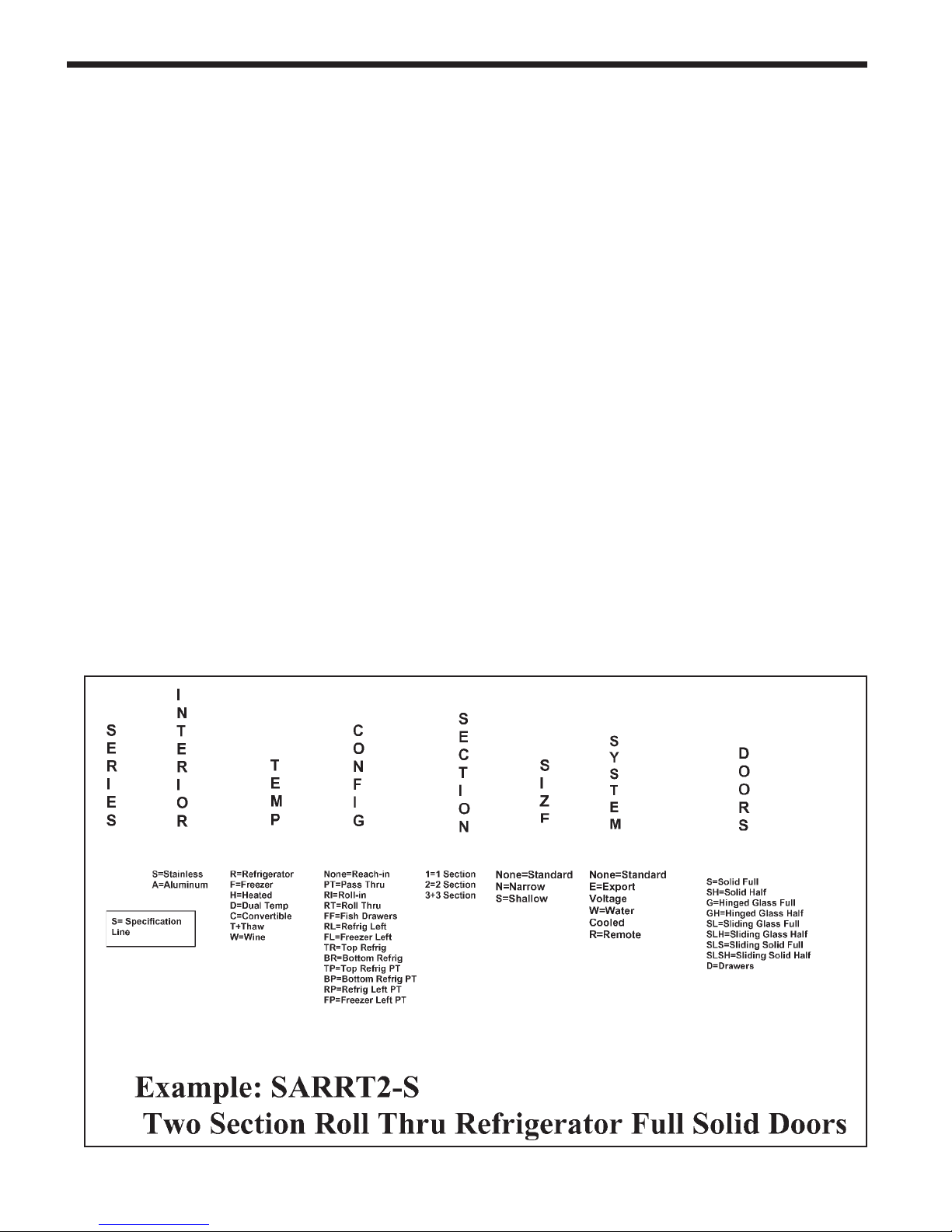
Model Number
The following chart (see below) describes the model
number system used in this manual.
Heating System
Heating system cabinets are designed to maintain temperatures between 120°F and 200°F. Heating elements
are helical shaped, with tubular fins. A circulating fan
provides uniform airflow in the cabinet. The entire heating
system is mounted to the exterior of the cabinet ceiling,
outside the food zone. It is assembled as one piece and
can be removed as one piece. An adjustable electronic
thermostat controls temperature. The system ON/OFF
switch is located on the front exterior of the cabinet.
Refrigeration System
All components are mounted to the exterior cabinet
ceiling, outside the food zone and are assembled as onepiece and can be removed as one-piece. Environmentally friendly R404A refrigerant is used. The system has
the capability of maintaining between 27°F and 44°F in
heavy use food service operations. Refrigerant is metered using a highly responsive thermostatic expansion
valve. System is controlled using Delfield’s ACT-Advanced Control Technology electronic temperature control, which provides improved pull down times, reducing
compressor cycling and longer compressor life with
lower energy consumption. Control system uses adaptive defrost to assure evaporator coil is free of ice and
operating at optimum efficiency. Evaporator condensate
is eliminated using an energy efficient hot gas system.
Freezer Refrigeration System
All components are mounted to the exterior cabinet ceiling,
outside the food zone and are assembled as one-piece and
can be removed as one-piece. Environmentally friendly
R404A refrigerant is used. The system has the capability
of maintaining between -5°F and 0°F in heavy use food
service operations. Refrigerant is metered using a highly
responsive thermostatic expansion valve. Evaporator defrost is automatic using a time initiated, time/temperature
terminated system with electric heaters. Evaporator condensate is eliminated using an energy efficient hot gas
system.
5
Delfield
Dual Temperature Refrigeration/Freezer
Each compartment has its own separate refrigeration system.
Condensing units are located on top of the cabinet, outside the
food zone, behind the removable upper shroud. Evaporator
coils are located inside the cabinet mounted to the interior
ceiling of each compartment. Defrost is automatic. Condensate travels down a tube in the cabinet sidewall to a receptacle
mounted to the exterior bottom of the cabinet where it evaporates with the aid of an electric heater. Each compartment’s
temperature is individually monitored and controlled. Two
exterior digital thermometers monitor temperature. Refrigerator compartment maintains temperature between 33°F and
41°F. Freezer compartment maintains temperature between
+5°F and -5°F. Refrigerant is metered using a highly responsive thermostatic expansion valve.
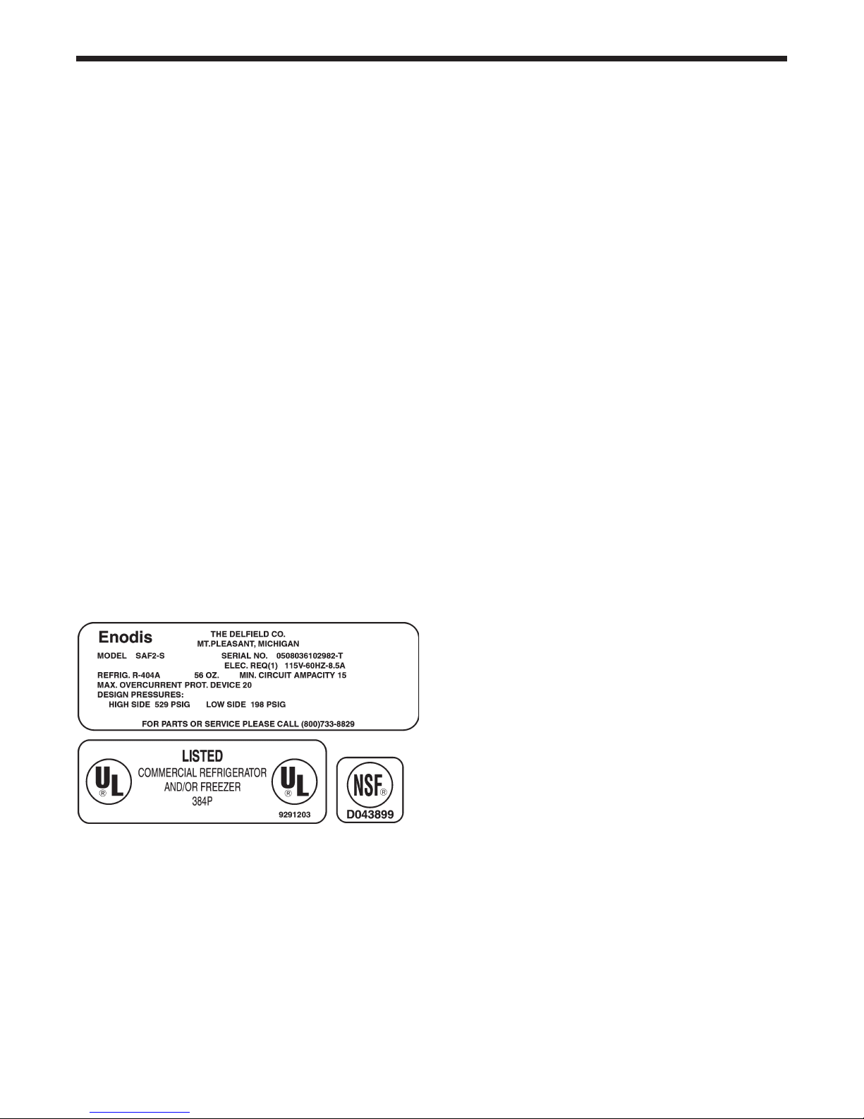
SERIAL NUMBER
Always have the serial number of your unit available
when calling for parts or service. The serial number is on
the identification plate that also includes the model
number. A typical identification plate is shown below. On
refrigeration and freezer unit the identification plate is
located inside the right most door (the only door on onedoor unit), near the top front corner of the right interior
wall. On heated units, the identification plate is located in
the shroud area on the right side panel. For parts and
services go to www.delfield.com.
RECEIVING AND INSPECTING
THE EQUIPMENT
Care should be taken during unloading so the equipment
is not damaged while being moved into the building.
1. Visually inspect the exterior of the package and
skid or container. Any damage should be noted
and reported to the delivering carrier immediately.
2. If damaged, open and inspect the contents with
the carrier.
3. In the event that the exterior is not damaged,
yet upon opening, there is concealed damage
to the equipment notify the carrier. Notification
should be made verbally as well as in written
form.
4. Request an inspection by the shipping company of the damaged equipment. This should
be done within 10 days from receipt of the
equipment.
5. Also inspect the heating package on heated
units and the compressor compartment housing and the refrigeration package on refrigerator and freezer units. Be sure lines are secure
and base is still intact.
7. Freight carriers can supply the necessary damage forms upon request.
8. Retain all shipping material until an inspection
has been made or waived.
6

Specification Line
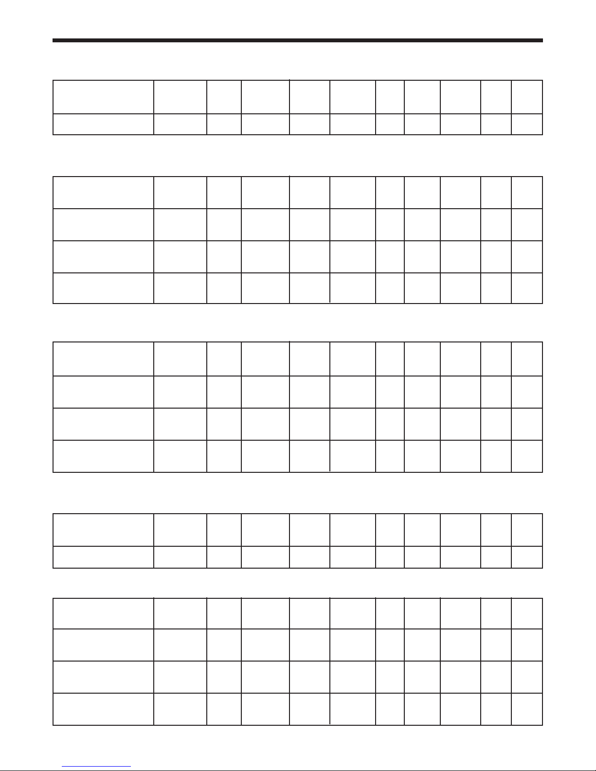
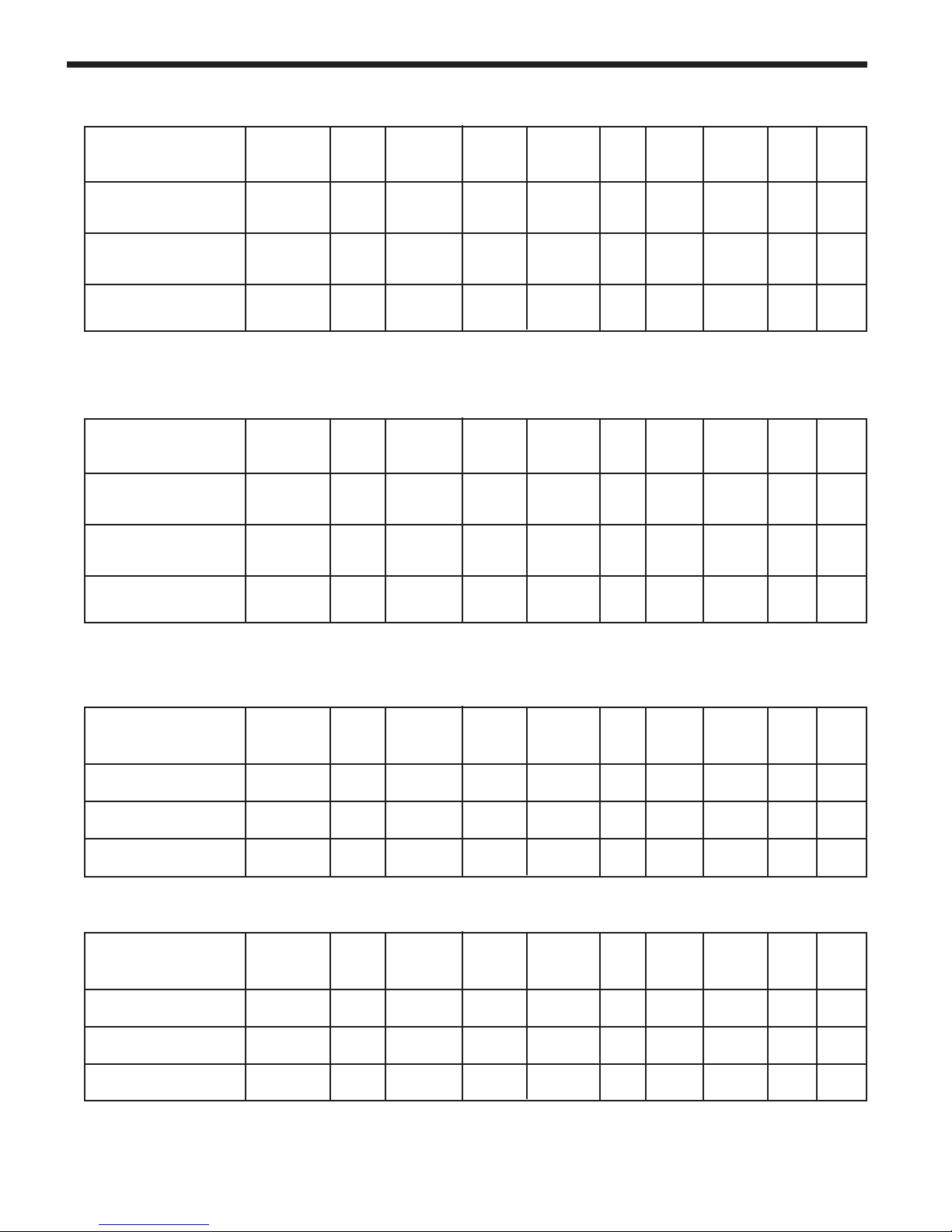
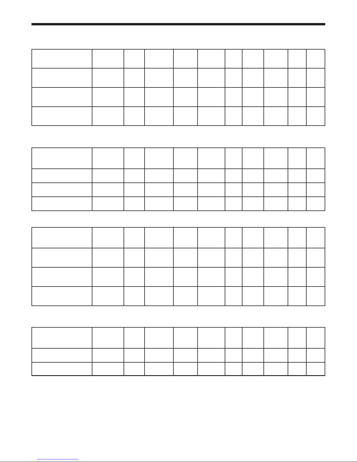
SPECIFICATIONS
HEATED ROLL-THRU
MODEL VOLTAGE AMPS STORAGE SHELVES NO. OF UNIT BTU/HR BTU/HR SHIP NEMA
NUMBER CU. FT. SQ. FT. SHELVES H.P. CAB SYSTEM WGT PLUG
SSHRT1-S, SAHRT1-S 120/208-240 9.0 38.58 N/A N/A N/A N/A N/A 504 N/A
SSHRT2-S, SAHRT2-S 120/208-240 16 79.74 N/A N/A N/A N/A N/A 806 N/A
SSHRT3-S, SAHRT3-S 120/208-240 17.8 120.90 N/A N/A N/A N/A N/A 940 N/A
SSHRT1-GS, SAHRT1-GS 120/208-240 9.0 38.58 N/A N/A N/A N/A N/A 519 N/A
SSHRT2-GS, SAHRT2-GS 120/208-240 16 79.74 N/A N/A N/A N/A N/A 836 N/A
SSHRT3-GS, SAHRT3-GS 120/208-240 17.8 120.90 N/A N/A N/A N/A N/A 985 N/A
SOLID DOOR HOT FOOD CABINET REACH-IN
LOAD CAP
MODEL VOLTAGE AMPS STORAGE SHELVES NO. OF UNIT BTU/HR BTU/HR SHIP NEMA
NUMBER CU. FT. SQ. FT. SHELVES H.P. CAB SYSTEM WGT PLUG
LOAD CAP
SSH1-S, SSH1-SH,
SAH1I-S, SAH1-SH 120/208-240 9.0 24.96 12.81 3 N/A N/A N/A 420 N/A
SSH2-S, SSH2-SH,
SAH2-S, SAH2-SH 120/208-240 16.0 51.92 27.54 6 N/A N/A N/A 562 N/A
SSH3-S, SSH3-SH,
SAH3-S, SAH3-SH 120/208-240 17.8 78.89 42.47 9 N/A N/A N/A 782 N/A
SELF CONTAINED SOLID DOOR HEATED ROLL-IN
MODEL VOLTAGE AMPS STORAGE SHELVES NO. OF UNIT BTU/HR BTU/HR SHIP NEMA
NUMBER CU. FT. SQ. FT. SHELVES H.P. CAB SYSTEM WGT PLUG
SSHRL1-S, SAHRL1-S, 120/208-240 9.0 36.15 12.81 N/A N/A N/A N/A 459 N/A
SSHRL2-S, SAHRL2-S, 120/208-240 12.2 74.72 12.81 N/A N/A N/A N/A 704 N/A
SSHRL3-S, SAHRL3-S, 120/208-240 10 113.28 12.81 N/A N/A N/A N/A 1008 N/A
LOAD CAP
SELF CONTAINED GLASS DOOR HEATED ROLL-IN
MODEL VOLTAGE AMPS STORAGE SHELVES NO. OF UNIT BTU/HR BTU/HR SHIP NEMA
NUMBER CU. FT. SQ. FT. SHELVES H.P. CAB SYSTEM WGT PLUG
SSHRL1-S, SAHRL1-S, 120/208-240 9.0 36.15 N/A N/A N/A N/A N/A 465 N/A
SSHRL2-S, SAHRL2-S, 120/208-240 16.0 74.72 N/A N/A N/A N/A N/A 7284 N/A
SSHRL3-S, SAHRL3-S, 120/208-240 17.8 113.28 N/A N/A N/A N/A N/A 1041 N/A
LOAD CAP
7
Delfield
SOLID DOOR NARROW HOT FOOD CABINET REACH-IN
MODEL VOLTAGE AMPS STORAGE SHELVES NO. OF UNIT BTU/HR BTU/HR SHIP NEMA
NUMBER CU. FT. SQ. FT. SHELVES H.P. CAB SYSTEM WGT PLUG
LOAD CAP
SSH2N-S SAH2N-S 115/208-240 16 51.92 27.54 6 N/A N/A N/A 596 N/A
GLASS DOOR HOT FOOD CABINET REACH-IN
MODEL VOLTAGE AMPS STORAGE SHELVES NO. OF UNIT BTU/HR BTU/HR SHIP NEMA
NUMBER CU. FT. SQ. FT. SHELVES H.P. CAB SYSTEM WGT PLUG
LOAD CAP
SSH1-G, SSH1-GH,
SAH1-G, SAH1-GH, 115/208-240 9.0 24.96 12.81 3 N/A N/A N/A 438 N/A
SSH2-G, SSH2-GH,
SAH2-G, SAH2-GH 115/208-240 16.0 51.92 27.54 6 N/A N/A N/A 569 N/A
SSH3-G, SSH3-GH,
SAH3G, SAH3GH 115/208-240 17.8 78.89 42.47 9 N/A N/A N/A 812 N/A
SELF CONTAINED SOLID DOOR WINE CABINET REACH-IN
MODEL VOLTAGE AMPS STORAGE SHELVES NO. OF UNIT BTU/HR BTU/HR SHIP NEMA
NUMBER CU. FT. SQ. FT. SHELVES H.P. CAB SYSTEM WGT PLUG
LOAD CAP
SSW1-S, SSW1-SH,
SAW1-S, SAW1-SH 115 8.5 24.96 12.81 3 ¼ 758 2015 418 5-15P
SSW1-S, SSW1-SH,
SAW1-S, SAW1-SH 115 12.8 51.92 27.54 6 1/3 1374 2522 650 5-20P
SSW1-S, SSW1-SH,
SAW1-S, SAW1-SH 115 8.9 78.89 42.47 9 ½ 1971 3637 830 5-15P
SELF CONTAINED SOLID DOOR READY THAW CABINET REACH-IN
MODEL VOLTAGE AMPS STORAGE SHELVES NO. OF UNIT BTU/HR BTU/HR SHIP NEMA
NUMBER CU. FT. SQ. FT. SHELVES H.P. CAB SYSTEM WGT PLUG
LOAD CAP
SST2-S, SST2-SH 115 12.8 51.92 27.54 6 1/3 1374 2522 650 5-20P
SELF CONTAINED GLASS DOOR WINE CABINET REACH-IN
MODEL VOLTAGE AMPS STORAGE SHELVES NO. OF UNIT BTU/HR BTU/HR SHIP NEMA
NUMBER CU. FT. SQ. FT. SHELVES H.P. CAB SYSTEM WGT PLUG
SSW1-G, SSW1-GH,
SAW1-G, SAW1-GH 115 8.5 24.96 12.81 3 ¼ 758 2015 418 5-15P
LOAD CAP
SSW2-G, SSW2-GH,
SAW2-G, SAW2-GH 115 12.8 51.92 27.54 6 1/3 1374 2522 650 5-20P
SSW3-G, SSW3-GH,
SAW3-G, SAW3-GH 115 8.9 78.89 42.47 9 1/2 1971 3637 830 5-15P
8
Specification Line
SELF CONTAINED SHALLOW SOLID DOOR REACH-IN REFRIGERATOR
MODEL VOLTAGE AMPS STORAGE SHELVES NO. OF UNIT BTU/HR BTU/HR SHIP NEMA
NUMBER CU. FT. SQ. FT. SHELVES H.P. CAB SYSTEM WGT PLUG
LOAD CAP
SSR1S-S, SSR1S-SH,
SAR1S-S, SAR1S-SH 115 8.5 24.96 12.81 3 ¼ 758 2015 418 5-15P
SSR2S-S, SSR2S-SH,
SAR2S-S, SAR2S-SH 115 12.8 51.92 27.54 6 1/3 1374 2522 650 5-20P
SSR3S-S, SSR3S-SH,
SAR3S-S, SAR3S-SH 115 8.9 78.89 42.47 9 ½ 1971 3637 830 5-15P
SELF CONTAINED SHALLOW HINGED GLASS DOOR REACH-IN REFRIGERATOR
MODEL VOLTAGE AMPS STORAGE SHELVES NO. OF UNIT BTU/HR BTU/HR SHIP NEMA
NUMBER CU. FT. SQ. FT. SHELVES H.P. CAB SYSTEM WGT PLUG
LOAD CAP
SSR1S-G, SSR1S-GH,
SAR1S-G, SAR1S-GH 115 8.5 24.96 12.81 3 ¼ 758 2015 418 5-15P
SSR2S-G, SSR2S-GH,
SAR2S-G, SAR2S-GH 115 12.8 51.92 27.54 6 1/3 1374 2522 650 5-20P
SSR3S-G, SSR3S-GH,
SAR3S-G, SAR3S-GH 115 8.9 78.89 42.47 9 ½ 1971 3637 830 5-15P
SELF CONTAINED SOLID DOOR ROLL-THRU REFRIGERATOR
MODEL VOLTAGE AMPS STORAGE SHELVES NO. OF UNIT BTU/HR BTU/HR SHIP NEMA
NUMBER CU. FT. SQ. FT. SHELVES H.P. CAB SYSTEM WGT PLUG
LOAD CAP
SSRRT1, SARRT1-S 115 10.3 38.58 N/A N/A ½ 1706 3120 494 5-15P
SSRRT2-S, SARRT2-S 115/208-230 10.1 79.74 N/A N/A ¾ 3263 69.20 736 N/A
SSRRT3-S, SARRT3-S 115/208-230 11.3 120.9 N/A N/A ¾ 4815 7569 1056 N/A
SELF CONTAINED GLASS DOOR ROLL-IN REFRIGERATOR
MODEL VOLTAGE AMPS STORAGE SHELVES NO. OF UNIT BTU/HR BTU/HR SHIP NEMA
NUMBER CU. FT. SQ. FT. SHELVES H.P. CAB SYSTEM WGT PLUG
LOAD CAP
SSRRL1-G, SARRL1-G 115 9.0 36.15 N/A N/A 1/3 1331 2614 487 5-15P
SSRRL2-G, SARRL2-G 115 12.2 74.72 N/A N/A ½ 2512 4046 798 5-15P
SSRRL3-G, SARRL3-G 115/208-230 10 113.28 N/A N/A ¾ 3687 7569 1152 N/A
9
Delfield
SELF CONTAINED HINGED GLASS DOOR PASS-THRU REFRIGERATOR
MODEL VOLTAGE AMPS STORAGE SHELVES NO. OF UNIT BTU/HR BTU/HR SHIP NEMA
NUMBER CU. FT. SQ. FT. SHELVES H.P. CAB SYSTEM WGT PLUG
LOAD CAP
SSRPT1-G, SSRPT1-GH,
SARPT1-G, SARPT-GH 115 12.8 26.64 12.81 3 1/3 1537 2614 476 5/20P
SSRPT2-G, SSRPT2-GH,
SARPT2-G, SARPT2-GH 115 11.2 55.42 27.54 6 ½ 3001 4096 740 5-15P
SSRPT3-G, SSRPT3-GH,
SARPT3-G, SARPT3-GH 115/208-230 12.4 84.19 42.27 9 ¾ 4451 7569 1032 14-20P
SELF CONTAINED SOLID DOOR ROLL-IN REFRIGERATOR
MODEL VOLTAGE AMPS STORAGE SHELVES NO. OF UNIT BTU/HR BTU/HR SHIP NEMA
NUMBER CU. FT. SQ. FT. SHELVES H.P. CAB SYSTEM WGT PLUG
LOAD CAP
SSRRL1-S, SARRL1-S 115 9.0 36.15 N/A N/A 1/3 1207 2354 476 5-15P
SSRRL2-S, SARRL2-S 115 12.2 74.72 N/A N/A ½ 2221 3637 768 5-15P
SSRRL3-S, SARRL3-S 115/208-230 10 113.28 N/A N/A ¾ 3229 6744 1044 N/A
SELF CONTAINED SOLID DOOR REACH-IN REFRIGERATOR
MODEL VOLTAGE AMPS STORAGE SHELVES NO. OF UNIT BTU/HR BTU/HR SHIP NEMA
NUMBER CU. FT. SQ. FT. SHELVES H.P. CAB SYSTEM WGT PLUG
LOAD CAP
SSR1-S, SSR1-SH,
SAR1-S, SAR1-SH 115 8.5 24.96 12.81 3 ¼ 758 2015 418 5-15P
SSR2-S, SSR2-SH,
SAR2-S, SAR2-SH 115 12.8 51.92 27.54 6 1/3 1374 2522 650 5-20P
SSR3-S, SSR3-SH,
SAR3-S, SAR3-SH 115 8.9 78.89 42.47 9 ½ 1971 3637 830 5-15P
SELF CONTAINED SHALLOW SOLID DOOR PASS-THRU REFRIGERATOR
MODEL VOLTAGE AMPS STORAGE SHELVES NO. OF UNIT BTU/HR BTU/HR SHIP NEMA
NUMBER CU. FT. SQ. FT. SHELVES H.P. CAB SYSTEM WGT PLUG
LOAD CAP
SSRPT1S, SARPT1S 115 12.8 26.64 12.81 3 1/3 968 2354 455 5-20P
SSRPT12S, SARPT2SS 115 11.2 55.42 27.54 6 ½ 1843 3637 700 5-15P
10
 Loading...