

Delfield 200 Series, 300 Series, N225, N225-E, N225L Installation, Operation And Maintenance Manual
...Page 1
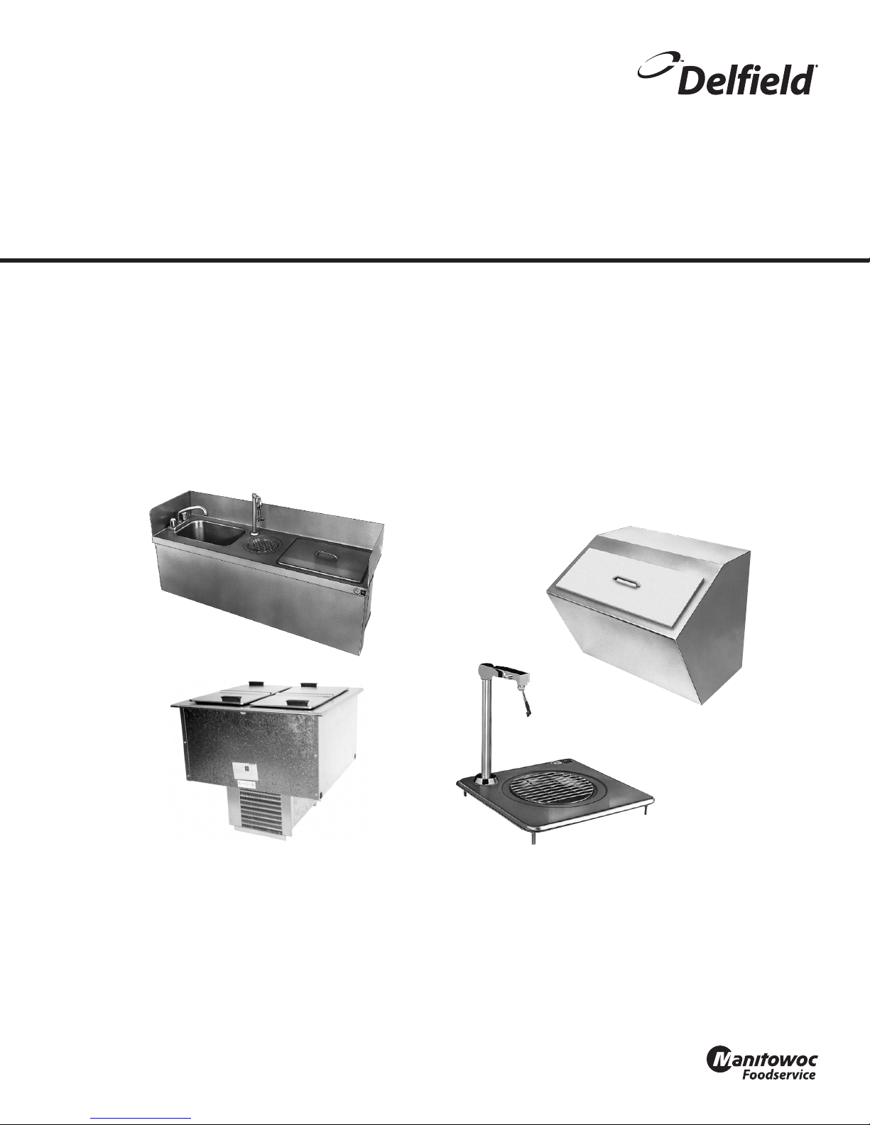
200 & 300 Series
Original Instructions
Installation, Operation and Maintenance Manual
This manual is updated as new information and models are released. Visit our website for the latest manual.
Part Number: 9291456 07/16
Page 2
Safety Notices
Warning
n
Read this manual thoroughly before operating, installing
or performing maintenance on the equipment. Failure
to follow instructions in this manual can cause property
damage, injury or death.
DANGER
Do not lift the condensing unit by the refrigerant tubing
or other components. These features will not support
the condensing unit weight. Injury and unit damage
may occur!
DANGER
Do not install or operate equipment that has been
misused, abused, neglected, damaged, or altered/
modified from that of original manufactured
specifications.
Warning
n
This product contains chemicals known to the State
of California to cause cancer and/or birth defects or
other reproductive harm. Operation, installation, and
servicing of this product could expose you to airborne
particles of glasswool or ceramic fibers, crystalline
silica, and/or carbon monoxide. Inhalation of airborne
particles of glasswool or ceramic fibers is known to the
State of California to cause cancer. Inhalation of carbon
monoxide is known to the State of California to cause
birth defects or other reproductive harm.
Warning
n
Do not use electrical appliances or accessories other
than those supplied by the manufacturer.
Warning
n
Use caution when handling metal surface edges of all
equipment.
DANGER
All utility connections and fixtures must be maintained
in accordance with Local and national codes.
DANGER
Keep power cord AWAY from HEATED surfaces. DO NOT
immerse power cord or plug in water. DO NOT let power
cord hang over edge of table or counter.
Warning
n
Authorized Service Representatives are obligated to
follow industry standard safety procedures, including,
but not limited to, local/national regulations for
disconnection / lock out / tag out procedures for all
utilities including electric, gas, water and steam.
Warning
n
This appliance is not intended for use by persons
(including children) with reduced physical, sensory
or mental capabilities, or lack of experience and
knowledge, unless they have been given supervision
concerning use of the appliance by a person responsible
for their safety. Do not allow children to play with this
appliance.
Warning
n
DO NOT touch refrigeration lines inside units; some may
exceed temperatures of 200°F (93.3°C).
Note
Proper installation, care and maintenance are
essential for maximum performance and trouble-free
operation of your equipment. Visit our website www.
mtwkitchencare.com for manual updates, translations,
or contact information for service agents in your area.
Warning
n
Do not store or use gasoline or other flammable vapors
or liquids in the vicinity of this or any other appliance.
Never use flammable oil soaked cloths or combustible
cleaning solutions, for cleaning.
Page 3

Section 1
General Information
Section 2
Installation
Section 3
Operation
Table of Contents
Model Numbers .................................................................................................................. 4
Serial Number Location ..................................................................................................... 4
Warranty Information ........................................................................................................ 4
Regulatory Certifications ..................................................................................................4
Domestic Models ....................................................................................................................................4
Export Models .........................................................................................................................................4
Location ..............................................................................................................................5
Clearance Requirements ....................................................................................................6
Weight Of Equipment ........................................................................................................6
Dimensions ......................................................................................................................... 6
Cutout Installation Dimension .......................................................................................... 7
Electrical Service ................................................................................................................ 9
Voltage .......................................................................................................................................................9
Ground Fault Circuit Interrupter .......................................................................................................9
Rated Amperages, Horsepower, Voltage & Power Cord Chart ...............................................9
Refrigeration ....................................................................................................................10
Drain Connections ............................................................................................................10
Section 4
Maintenance
N225 & N227 Operation ...................................................................................................11
Cleaning and Sanitizing Procedures ...............................................................................13
Interior & Exterior ................................................................................................................................ 13
N225 & N227 Cleaning the Condenser Coil ............................................................................... 14
N225 & N227 Defrosting ................................................................................................................... 14
Part Number: 9291456 07/16 3
Page 4
Section 1
General Information
Model Numbers
Model Description
203 Drop-in ice chest with cover
204
204P
240 Drop-in ice chest with cover
250 Undercounter sink, ice chest and water station
305 Drop-in ice chest with cover
307 Drop-in glass ller
N225
N225-E
N225L
N225L-E
N227
N227-E
N227L
N227L-E
Drop-in water and ice station
Drop-In Freezers
Drop-In Freezers With Lexan® Lid
Drop-In Freezers
Drop-In Freezers With Lexan® Lid
Serial Number Location
Always have the serial number of your unit available
when calling for parts or service.
Model Serial Tag Location
203
204P
240 On the back
250
305
307 Underneath the top
N225
N225-E
N225L
N225L-E
N227
N227-E
N227L
N227L-E
Bottom of the ice chest204
Bottom of the ice chest
On the compressor stand next to the
temperature control
Regulatory Certifications
DOMESTIC MODELS
All domestic models are certified by:
•
All domestic electrical models are certified by:
•
•
EXPORT MODELS
All export models are certified by:
•
Export electrical models are certified by:
• Technical Inspection Association
• European Conformity
National Sanitation Foundation (NSF)
Underwriters Laboratories (UL)
Underwriters Laboratories of Canada (CUL)
National Sanitation Foundation (NSF)
Warranty Information
• Register your product for warranty,
• Verify warranty information,
• View and download a copy of your warranty,
at www.delfield.com/warranty
Part Number: 9291456 07/16 4
Page 5
Section 2
Installation
DANGER
Installation must comply with all applicable fire and
health codes in your jurisdiction.
DANGER
Use appropriate safety equipment during installation
and servicing.
Warning
n
This equipment is intended for indoor use only. Do not
install or operate this equipment in outdoor areas.
Caution
,
Do not position the air intake vent near steam or heat
exhaust of another appliance.
Warning
n
Remove all removable panels before lifting and
installing.
Warning
n
Do not damage the refrigeration circuit when installing,
maintaining or servicing the unit.
Location
Warning
n
This equipment must be positioned so that the plug is
accessible unless other means for disconnection from
the power supply (e.g., circuit breaker or disconnect
switch) is provided.
Warning
n
Adequate means must be provided to limit the
movement of this appliance without depending on or
transmitting stress to the electrical conduit.
Warning
n
To avoid instability the installation area must be capable
of supporting the combined weight of the equipment
and product. Additionally the equipment must be level
side to side and front to back.
The location selected for the equipment must meet the
following criteria. If any of these criteria are not met, select
another location.
• Units are intended for indoor use only.
• The location MUST be level, stable and capable of
supporting the weight of the equipment.
• The location MUST be free from and clear of
combustible materials.
• Equipment MUST be level both front to back and side to
side.
• Position the equipment so it will not tip or slide.
• Recommended air temperature is 41° - 86°F (5° - 30°C).
• Proper air supply for ventilation is REQUIRED AND
CRITICAL for safe and efficient operation. Refer to
Clearance Requirements chart on page 6.
• Do not obstruct the flow of ventilation air. Make sure the
air vents of the equipment are not blocked.
• Do not install the equipment directly over a drain.
Steam rising up out of the drain will adversely affect
operation, air circulation, and damage electrical /
electronic components.
Part Number: 9291456 07/16 5
Page 6
Installation Section 2
Clearance Requirements
DANGER
Minimum clearance requirements are the same for
noncombustible locations as for combustible locations.
The flooring under the appliance must be made of a
noncombustible material.
DANGER
Risk of fire/shock. All minimum clearances must be
maintained. Do not obstruct vents or openings.
Condensing Unit Bottom & Sides
0” (0cm)
• Keep the vents clean and free of obstruction.
Weight Of Equipment
Model Ship Weight
203 52lbs (24kg)
204 47.5lbs (22kg)
204P 47.5lbs (22kg)
240 36lbs (16kg)
250 81lbs (37kg)
305 18lbs (8kg)
307 7lbs (3kg)
N225 115lbs (52kg)
N225-E 115lbs (52kg)
N225L 115lbs (52kg)
N225L-E 115lbs (52kg)
N227 191lbs (87kg)
N227-E 191lbs (87kg)
N227L 191lbs (87kg)
N227L-E 191lbs (87kg)
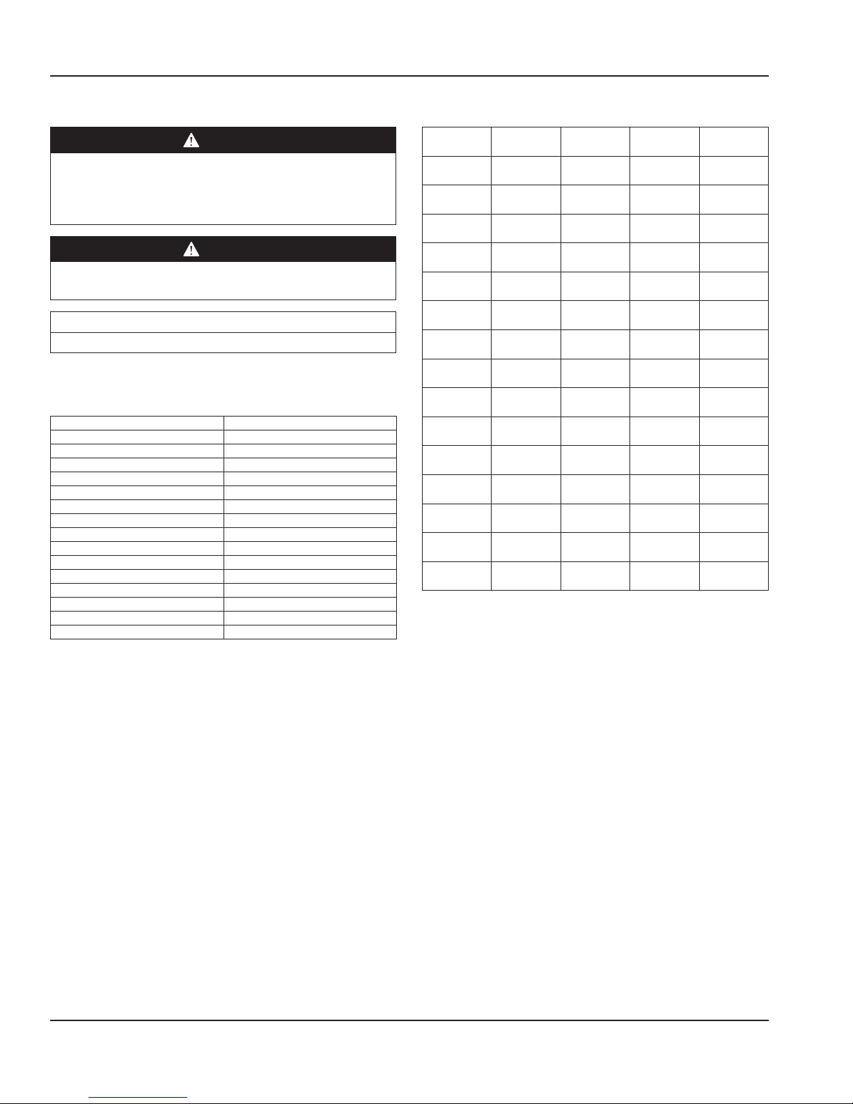
Dimensions
Model L D H Cabinet
203 20.25”
(51.4cm)
204 24”
(61.0cm)
204P 24”
(61.0cm)
240 21”
(53.3cm)
250 46”
(116.8cm)
305 21.25”
(54.0cm)
307 12”
(30.5cm)
N225 16.56”
(42.1cm)
N225-E 16.56”
(42.1cm)
N225L 16.56”
(42.1cm)
N225L-E 16.56”
(42.1cm)
N227 30”
(76.2cm)
N227-E 30”
(76.2cm)
N227L 30”
(76.2cm)
N227L-E 30”
(76.2cm)
20.25”
(51.4cm)
21”
(53.3cm)
21”
(53.3cm)
17.5”
(44.5cm)
14.06”
(36cm)
15.25”
(38.7cm)
12”
(30.5cm)
27.87”
(70.8cm)
27.87”
(70.8cm)
27.87”
(70.8cm)
27.87”
(70.8cm)
27.87”
(70.8cm)
27.87”
(70.8cm)
27.87”
(70.8cm)
27.87”
(70.8cm)
23.25”
(59.1cm)
22.6”
(57cm)
26.35”
(67cm)
17”
(43.2cm)
22.75”
(57.8cm)
13”
(33.0cm)
9.5”
(24.1cm)
26.75”
(67.9cm)
26.75”
(67.9cm)
26.75”
(67.9cm)
26.75”
(67.9cm)
26.75”
(67.9cm)
26.75”
(67.9cm)
26.75”
(67.9cm)
26.75”
(67.9cm)
Capacity
90lbs
(41kg)
45lbs
(20kg)
45lbs
(20kg)
75lbs
(34kg)
45lbs
(20kg)
45lbs
(20kg)
—
6 gal.
6 gal.
6 gal.
6 gal.
12 gal.
12 gal.
12 gal.
12 gal.
6 Part Number: 9291456 07/16
Page 7
Section 2 Installation
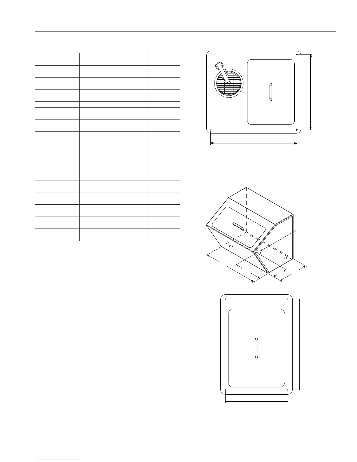
204/204P Stud Location
Cutout Installation Dimension
Model Cutout Size Mounting
203 19.25” x 19.25”
(49cm x 49cm)
204 21” x 17.75”
(53.3cm x 45.1cm)
204P 21” x 17.75”
(53.3cm x 45.1cm)
240 NA NA
250 45” x 13”
(114.3cm x 33.0cm)
305 12.5” x 17.75”
(31.8cm x 45.1cm)
307 9.00” x 9.00”
(23cm x 23cm)
N225 25.75” x 14.62”
(65.4cm x 37.1cm)
N225-E 25.75” x 14.62”
(65.4cm x 37.1cm)
N225L 25.75” x 14.62”
(65.4cm x 37.1cm)
N225L-E 25.75” x 14.62”
(65.4cm x 37.1cm)
N227 25.75” x 28.00”
(65.4cm x 71.1cm)
N227-E 25.75” x 28.00”
(65.4cm x 71.1cm)
N227L 25.75” x 28.00”
(65.4cm x 71.1cm)
N227L-E 25.75” x 28.00”
(65.4cm x 71.1cm)
Studs
NA
4
4
NA
4
4
NA
NA
NA
NA
NA
NA
NA
NA
204 & 204P Cutout Details
19.25” (48.9cm)
22.00” (55.9cm)
204/204P Stud Location
240 Details
Ice chest with cover, model 240 can be set on a counter
or plate shelf. Select the desired location. Mark the drain
location and drill a 1.50” (4cm) diameter hole.
1.25” (3cm) Dia. OD
Mounting Studs
Mark the stud locations according to the measurements
or place the equipment in the cutout to mark the stud
locations. Drill 0.37” (1.0cm) diameter holes through the
counter for the studs.
203 Details
When mounting a 203 ice chest into a wood counter secure
it with provided clips. When mounting into a stainless steel
counter, use silicone.
20.68”
(53cm)
305 Cutout Details
10.34”
(26cm)
13.25” (33.7cm)
305 Stud Location
5.13”
(13cm)
11.19”
(28cm)
19.375” (49.2cm)
305 Stud Location
Part Number: 9291456 07/16 7
Page 8
Installation Section 2
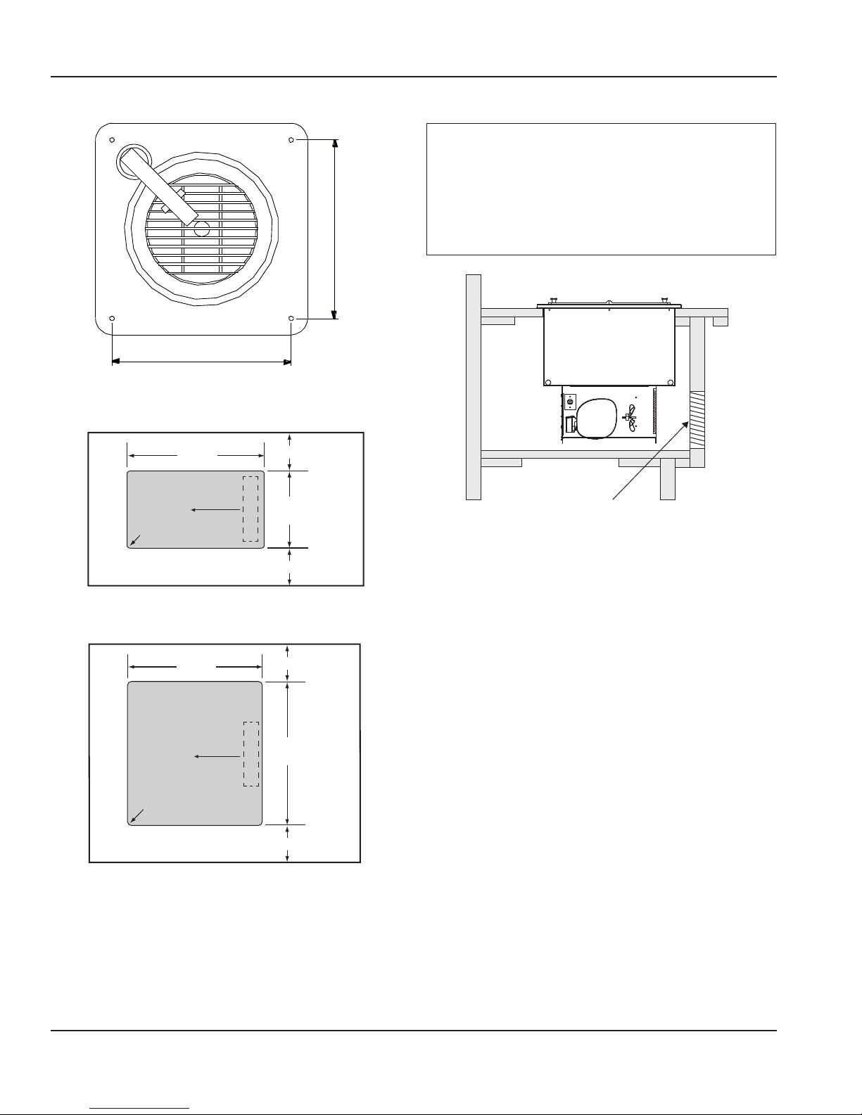
307 Stud Location
307 Cutout Details
10.12” (25.7cm)
307 Stud Location
N225 Cutout Details
Cutout
.75"/1.9cm
radius
Countertop
N227 Cutout Details
25.75"
65.4cm
Air Flow
1.00"/2.5cm (min.)
14.62"
37.1cm
Finned Coil
1.00"/2.5cm (min.)
10.12” (25.7cm)
N225 & N227 louver Details
Note
The louver provided must be installed in front of the
condensing unit’s finned coil. A second cutout must be
made at the opposite end of the equipment to allow
air flow through the unit. No louver is provided for the
second cutout. Any restriction to the proper air flow,
total or partial, will void the compressor warranty.
N225 N225L N227 or
N227L DROP-IN
Typical
Counter
Cabinet
Louver in front of the finned coil measures
13.00" x 25.00" (33.0cm x 63.5cm)
Louver Cutout Size is 12.00" x 23.50"
(30.5cm x 59.7cm) (typical installation)
NOTE: A second cutout (without louver) must be
made opposite the finned coil to allow proper air flow.
Finned Coil
25.75"
65.4cm
1.00"/2.5cm (min.)
Cutout
28.0"
71.1cm
Finned Coil
1.00"/2.5cm (min.)
.75"/1.9cm
radius
Countertop
Air Flow
8 Part Number: 9291456 07/16
Page 9
Section 2 Installation
Electrical Service
DANGER
Check all wiring connections, including factory
terminals, before operation. Connections can become
loose during shipment and installation.
Warning
n
This appliance must be grounded and all field wiring
must conform to all applicable local and national
codes. Refer to rating plate for proper voltage. It is the
responsibility of the end user to provide the disconnect
means to satisfy the authority having jurisdiction.
VOLTAGE
All electrical work, including wire routing and grounding,
must conform to local, state and national electrical codes.
The following precautions must be observed:
• The equipment must be grounded.
• A separate fuse/circuit breaker must be provided for
each unit.
• A qualified electrician must determine proper wire size
dependent upon location, materials used and length
of run (minimum circuit ampacity can be used to help
select the wire size).
• The maximum allowable voltage variation is ±10% of
the rated voltage at equipment start-up (when the
electrical load is highest).
• Check all green ground screws, cables and wire
connections to verify they are tight before start-up.
RATED AMPERAGES, HORSEPOWER, VOLTAGE &
POWER CORD CHART
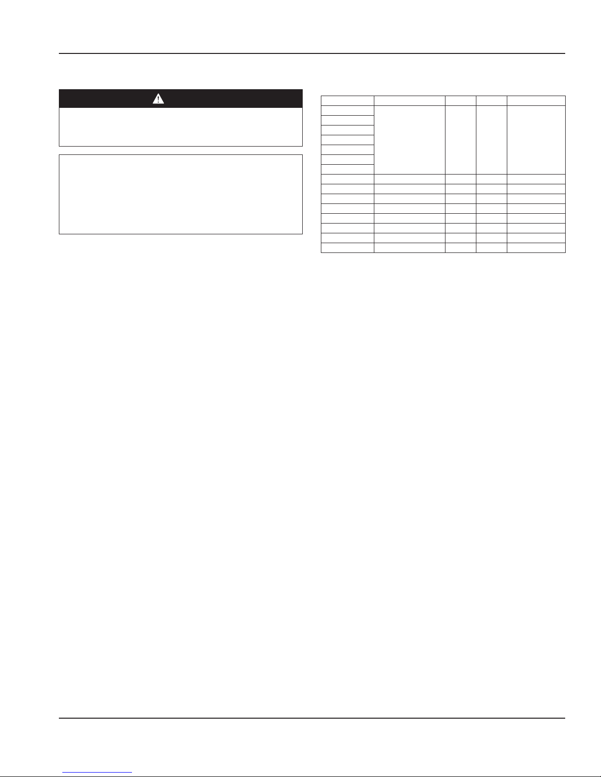
Model V/Hz/Ph Amp H.P. Plug
203
204
204P
240
250
305
307
N225 115/60/1 5.3 1/5 NEMA 5-15P
N225-E 230-240/50/1 1.1 1/5 CEE 7/7
N225L 115/60/1 5.3 1/5 NEMA 5-15P
N225L-E 230-240/50/1 1.1 1/5 CEE 7/7
N227 115/60/1 5.3 1/5 NEMA 5-15P
N227-E 230-240/50/1 1.7 1/4 CEE 7/7
N227L 115/60/1 5.3 1/5 NEMA 5-15P
N227L-E 230-240/50/1 1.7 1/4 CEE 7/7
N/A N/A N/A N/A
GROUND FAULT CIRCUIT INTERRUPTER
Ground Fault Circuit Interrupter (GFCI/GFI) protection is
a system that shuts down the electric circuit (opens it)
when it senses an unexpected loss of power, presumably
to ground. Manitowoc does not recommend the use of
GFCI/GFI circuit protection to energize our equipment.
If code requires the use of a GFCI/GFI then you must
follow the local code. The circuit must be dedicated, sized
properly and there must be a panel GFCI/GFI breaker. We
do not recommend the use of GFCI/GFI outlets to energize
our equipment as they are known for more intermittent
nuisance trips than panel breakers.
Part Number: 9291456 07/16 9
Page 10
Installation Section 2
Refrigeration
Model Design Load
203
204
204P
240
250
305
307
N225 292 411 20/20°/-23°
N225-E 292 411 20/20°/-23°
N225L 292 411 20/20°/-23°
N225L-E 292 411 20/20°/-23°
N227 473 532 28/19°/-22
N227-E 473 532 28/19°/-22
N227L 473 532 28/19°/-22
N227L-E 473 532 28/19°/-22
BTU
N/A N/A N/A
System Cap.
BTU
Evap BTU/TD/
Temp
Drain Connections
Warning
n
If a mechanically cooled refrigerated base does not have
a condensate evaporator supplied, you must connect
the condensate line to a suitable drain. Otherwise, water
will collect on the floor, causing a potentially hazardous
situation.
Water Connection
Warning
n
Connect to a potable water supply only.
All 1/2” (1.3cm) IPS water inlets must be field connected
following local code requirements.
Drain
Provided 1” (2.5cm) drain, nut and washer must be
field installed to an appropriate container or floor drain
following local code requirements. Sinks come standard
with 1-1/2” basket strainer assemblies.
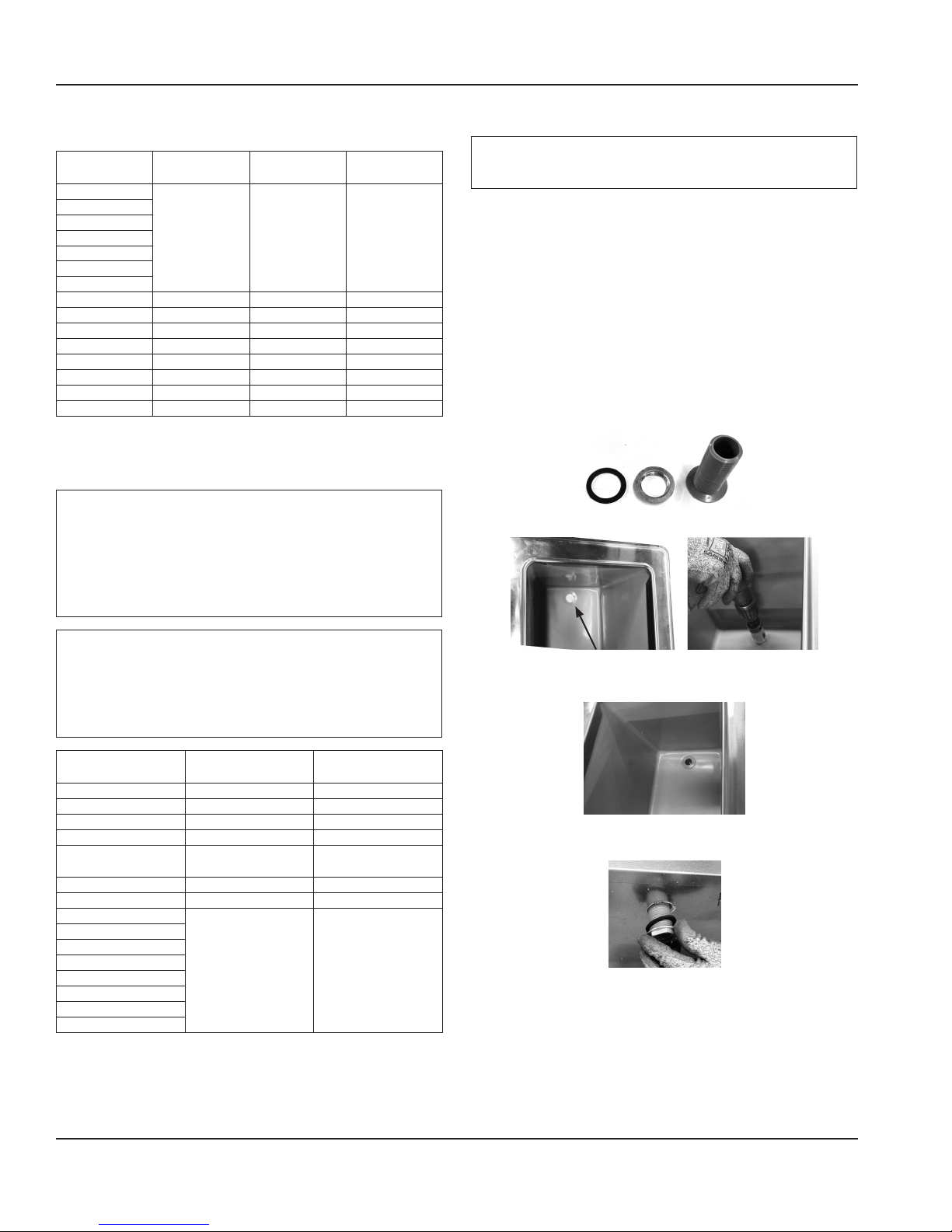
Drain Installation Instructions
1. Drain kit should include a drain, washer and nut.
2. Remove/drill foam out of drain hole.
Warning
n
Moisture collecting from improper drainage can create a
slippery surface on the floor and a hazard to employees.
It is the owner’s responsibility to provide a container or
outlet for drainage.
Model Drain 1/2” IPS Water
203 (1) 1” NA
204 (2) 1” 1
204P (2) 1” 1
240 (1) 1” NA
250 (2) 1”
305 (1) 1” NA
307 (1) 1” 1
N225
N225-E
N225L
N225L-E
N227
N227-E
N227L
N227L-E
(1) 1-1/2”
NA NA
Hookup
3
3. Apply thin ring of plumbers putty around the drain.
4. From the inside drop the drain into the drain hole.
5. From the outside secure the drain with the washer and
nut.
6. Tighten the nut with channel locks, use a fork to hold
the drain in place if necessary.
7. Clean up excess plumbers putty.
10 Part Number: 9291456 07/16
Page 11
Section 3
Operation
DANGER
The on-site supervisor is responsible for ensuring that
operators are made aware of the inherent dangers of
operating this equipment.
DANGER
Do not operate any appliance with a damaged cord
or plug. All repairs must be performed by a qualified
service company.
DANGER
Never stand on the unit! They are not designed to
hold the weight of an adult, and may collapse or tip if
misused in this manner.
Warning
n
Do not contact moving parts.
Warning
n
All covers and access panels must be in place and
properly secured, before operating this equipment.
N225 & N227 Operation
The models 225 and 227 are designed to hold frozen
products at a temperature range of 5°F to -5°F (-15°C
to -21°C). The thermostat is located in the machine
compartment.
After installation, the unit will begin operating simply
by plugging it into the proper outlet. If the unit does
not operate after being plugged in, check to see if the
thermostat is in the OFF position.
Warning
n
Damp or wet hands may stick to cold surfaces.
Warning
n
Never use sharp objects or tools to remove ice or frost.
Do not use mechanical devices or other means to
accelerate the defrosting process.
Warning
n
The operator of this equipment is solely responsible
for ensuring safe holding temperature levels for all
food items. Failure to do so could result in unsafe food
products for customers.
Caution
,
Do not block the supply and return air grills or the air
space around the air grills. Keep plastic wrappings,
paper, labels, etc. from being airborne and lodging in
the grills. Failure to keep the air grills clear will result in
unsatisfactory operation of the system.
Part Number: 9291456 07/16 11
Page 12

Operation Section 3
THIS PAGE INTENTIONALLY LEFT BLANK
12 Part Number: 9291456 07/16
Page 13
Section 4
Maintenance
DANGER
It is the responsibility of the equipment owner to
perform a Personal Protective Equipment Hazard
Assessment to ensure adequate protection during
maintenance procedures.
Disconnect electric power at the main power disconnect
for all equipment being serviced. Observe correct
polarity of incoming line voltage. Incorrect polarity can
lead to erratic operation.
DANGER
Failure to disconnect the power at the main power
supply disconnect could result in serious injury or death.
The power switch DOES NOT disconnect all incoming
power.
Maintenance Daily Weekly Monthly
Interior & Exterior X X X
Lid and/or Gasket X X X X
N225 & N227
Condenser Coil
Never use sharp objects or tools to remove ice or frost.
Do not use mechanical devices or other means to
accelerate the defrosting process.
After Prolonged
X X X
DANGER
Warning
n
Shutdown
At Start-Up
Cleaning and Sanitizing Procedures
Warning
n
When using cleaning fluids or chemicals, rubber gloves
and eye protection (and/or face shield) must be worn.
Caution
,
Maintenance and servicing work other than cleaning as
described in this manual must be done by an authorized
service personnel.
Note
When cleaning the unit, care should be taken to avoid
the power cord. Keep water and/or cleaning solutions
away from these parts.
Note
Never use a high-pressure water jet for cleaning or
hose down or flood the units with water. Do not use
power cleaning equipment, steel wool, scrapers or wire
brushes on stainless steel or painted surfaces.
Note
Never use an acid based cleaning solution! Many food
products have an acidic content, which can deteriorate
the finish. Be sure to clean the stainless steel surfaces of
ALL food products.
INTERIOR & EXTERIOR
You are responsible for maintaining the equipment
in accordance with the instructions in this manual.
Maintenance procedures are not covered by the warranty.
Clean the lid and the unit daily or more often to maintain
cleanliness and efficient operation.
Gaskets require daily cleaning to prevent mold and mildew
build up and also to retain the elasticity of the gasket.
Gasket cleaning can be done with the use of warm soapy
water. Avoid full strength cleaning products on gaskets as
this can cause them to become brittle and crack. Never use
sharp tools or knives to scrape or clean the gasket.
Wipe surfaces with a damp cloth rinsed in water to remove
dust and dirt from the unit. Always rub with the “grain” of
Part Number: 9291456 07/16 13
Page 14

Maintenance Section 4
the stainless steel to avoid marring the finish. If a greasy
residue persists, use a damp cloth rinsed in a mild dish soap
and water solution. Wipe dry with a clean, soft cloth.
Never use steel wool or abrasive pads for cleaning. Never
use chlorinated, citrus based or abrasive cleaners.
Stainless steel has a clear coating that is stain resistant and
easy to clean. Products containing abrasives will damage
the coating and scratch the panels. Daily cleaning may be
followed by an application of stainless steel cleaner which
will eliminate water spotting and fingerprints. Early signs of
stainless steel breakdown are small pits and cracks. If this
has begun, clean thoroughly and start to apply stainless
steel cleaners in attempt to restore the steel.
N225 & N227 CLEANING THE CONDENSER COIL
In order to maintain proper refrigeration performance, the
condenser fins must be cleaned of dust, dirt and grease
regularly. It is recommended that this be done monthly. If
conditions are such that the condenser is totally blocked
in a month, the frequency of cleaning should be increased.
Clean the condenser with a vacuum cleaner or stiff brush. If
extremely dirty, a commercially available condenser cleaner
may be required.
Failure to maintain a clean condenser coil can initially cause
high temperatures and excessive run times. Continuous
operation with a dirty or clogged condenser coil can
result in compressor failure. Neglecting the condenser coil
cleaning procedures will void any warranties associated
with the compressor and cost to replace the compressor.
N225 & N227 DEFROSTING
Mechanically cooled freezers should be defrosted after 3/8”
of ice accumulation. To defrost disconnect power to the
equipment or turn the thermostat knob to the OFF position.
Never use sharp objects or tools to clean or scrape ice/frost
build up from the refrigerated cold pans. A puncture could
cause irreparable damage to the refrigeration system.
14 Part Number: 9291456 07/16
Page 15

Page 16
DELFIELD
980 SOUTH ISABELLA ROAD, MOUNT PLEASANT, MI 48858
800-733-8821
WWW.DELFIELD.COM
Every new piece of Manitowoc Foodservice equipment comes with KitchenCare™ and you choose the level of service that meets
your operational needs from one restaurant to multiple locations.
StarCare – Warranty & lifetime service, certied OEM parts, global parts inventory, performance audited
ExtraCare — CareCode, 24/7 Support, online/mobile product information
LifeCare – Install & equipment orientation, planned maintenance, KitchenConnect™, MenuConnect
Talk with KitchenCare™ • 1-844-724-CARE • www.mtwkitchencare.com
To learn how Manitowoc Foodservice and its leading brands can equip you, visit our global web site at
www.manitowocfoodservice.com, then discover the regional or local resources available to you.
©2016 Manitowoc Foodservice except where explicitly stated otherwise. All rights reserved. Continuing product improvement may necessitate change of specications without notice.
Part Number: 9291456 07/16
 Loading...