

Page 1
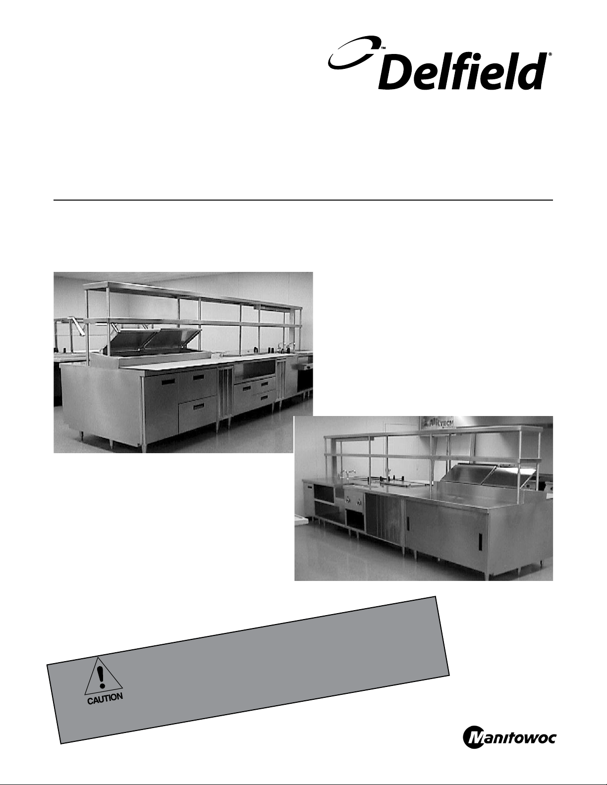
Component Crafted Custom Equipment - Line Ups
Service, Installation and Care Manual
Please read this manual completely before attempting to install or operate this equipment! Notify carrier
of damage! Inspect all components immediately.
IMPORTANT INFORMATION
READ BEFORE USE
PLEASE SAVE THESE INSTRUCTIONS!
Effective July 2010
Page 2
Component Crafted Custom Equipment - Line Ups Service and Installation Manual
Important Warning And Safety Information
WARNING Read This Manual Thoroughly Before Operating, Installing, Or Performing
Maintenance On The Equipment.
WARNING Failure To Follow Instructions In This Manual Can Cause Property Damage,
Injury Or Death.
WARNING Do Not Store Or Use Gasoline Or Other Flammable Vapors Or Liquids In The
Vicinity Of This Or Any Other Appliance.
WARNING Unless All Cover And Access Panels Are In Place And Properly Secured, Do
Not Operate This Equipment.
WARNING Do Not Clean With Water Jet.
CAUTION Observe the following:
Minimum clearances must be maintained from all walls and combustible
•
materials.
Keep the equipment area free and clear of combustible material.
•
Adequate clearance for air openings.
•
Operate equipment only on the type of electricity indicated on the
•
specification plate.
Retain this manual for future reference.
•
2
For customer service, call (800) 733-8829 or (800) 733-8948, Fax (989) 773-3210, www.delfield.com
Page 3
Component Crafted Custom Equipment - Line Ups Service and Installation Manual
Contents Receiving The Equipment
Receiving The Equipment .....................................................3
Tools And Supplies Required ................................................4
Maintenance ......................................................................4-5
Mark7 Fasteners ...................................................................6
Checking The Utility Rough-In ..............................................7
Splining Overview .................................................................7
Assembly And Installation ....................................................8
Curb-Mount Installation ........................................................8
Attachment Methods .............................................................9
Power Supply Information ....................................................9
Toe Plate Installation ...........................................................10
Counter Protector Installation .............................................11
Overshelf Installation ..........................................................11
Finished Back Panel Installation ..........................................12
Tray Slide Installation ..........................................................12
Standard Labor Guidelines ..................................................13
Standard Warranty ..............................................................14
Additional 4 Year Warranty .................................................15
Although most Delfield equipment is shipped crated, care
should be taken so the equipment is not damaged during
unloading and movement into the building.
Upon receipt of the shipment, be sure all items are included
and are undamaged. If there is damage, see the section on
“filing Freight Claims” for information on claims procedures.
All Delfield Custom Systems line-ups have been assembled
at the factory before shipment. Each unit is marked with the
work order number, item number and serial number. The
unit item number is identical to that marked on the sales
presentation drawing. Use these numbers as a guide during
installation.
Bolts, screws and other accessories needed for fastening
units together are in an envelope located inside one of the
units. The unit is marked with a note attached to the front.
©2010 The Delfield Company. All rights reserved.
Reproduction without written permission is prohibited.
SERIAL #
MODEL #
INSTALLATION DATE:
Receiving And Inspecting The Equipment
Even though most equipment is shipped crated, care should
be taken during unloading so the equipment is not damaged
while being moved into the building.
1. Visually inspect the exterior of the package and skid or
container. Any damage should be noted and reported to
the delivering carrier immediately.
2. If damaged, open and inspect the contents with the
carrier.
3. In the event that the exterior is not damaged, yet upon
opening, there is concealed damage to the equipment
notify the carrier. Notification should be made verbally
as well as in written form.
4. Request an inspection by the shipping company of the
damaged equipment. This should be done within 10
days from receipt of the equipment.
5. Check the lower portion of the unit to be sure legs or
casters are not bent.
6. Also open the compressor compartment housing and
visually inspect the refrigeration package. Be sure lines
are secure and base is still intact.
7. Freight carriers can supply the necessary damage forms
upon request.
8. Retain all crating material until an inspection has been
made or waived.
Uncrating the Equipment
First cut and remove the banding from around the crate.
Remove the front of the crate material, use of some tools will
be required. If the unit is on legs remove the top of the crate
as well and lift the unit off the skid. If the unit is on casters it
can be "rolled" off the skid.
For customer service, call (800) 733-8829 or (800) 733-8948, Fax (989) 773-3210, www.delfield.com
3
Page 4
Component Crafted Custom Equipment - Line Ups Service and Installation Manual
W ARE
Tools And Supplies Required
A steel hammer and a block of wood can be used to make
Units represented in this manual are for indoor use only.
The following tools are either required or will
make the installation easier:
A scissor jack to lift and hold heavy units off the floor so
1)
that legs can be adjusted, allowing the proper leveling of
the units.
A level is needed to assist in the leveling of each unit
2)
from front to back and left to right. A 2’ (61cm) level is a
must; a 4’ (122cm) level is also desirable.
Two 6’ (183cm) pipe clamps are useful in pulling
3)
equipment tightly together while fasteners are installed.
This results in a better spline.
Vise grips will hold backsplash bars together as they are
4)
being bolted together.
Maintenance
5)
minor alterations of the stainless steel along the seam
between two units, in order to perfect the seam. This is
used after the units are splined.
A rubber mallet.
6)
A socket set.
7)
Phillips, hex head and straight blade screwdrivers.
8)
7/16” (1.1cm), 9/16” (1.4cm) and 1/2” (1.3cm) open end
9)
wrenches.
Silicone sealant; Dow Corning #732 is ideal.
10)
Stainless Steel Care and Cleaning
To prevent discoloration of rust on stainless steel several
important steps need to be taken. First, we need to understand
the properties of stainless steel. Stainless steel contains 70-80%
iron which will rust. It also contains 12-30% chromium which
forms an invisible passive film over the steels surface which
acts as a shield against corrosion. As long as the protective
layer is intact, the metal is still stainless. If the film is broken
or contaminated, outside elements can begin to breakdown the
steel and begin to form rust of discoloration.
Proper cleaning of stainless steel requires soft cloths or plastic
scouring pads.
NEVER USE STEEL PADS, WIRE BRUSHES OR
SCRAPERS!
Cleaning solutions need to be alkaline based or non-chloride
cleaners. Any cleaner containing chlorides will damage
the protective film of the stainless steel. Chlorides are also
commonly found in hard water, salts, and household and
industrial cleaners. If cleaners containing chlorides are used be
sure to rinse repeatedly and dry thoroughly upon completion.
Routine cleaning of stainless steel can be done with soap and
water. Extreme stains or grease should be cleaned with a nonabrasive cleaner and plastic scrub pad. It is always good to
rub with the grain of the steel. There are also stainless steel
cleaners available which can restore and preserve the finish of
the steels protective layer.
Early signs of stainless steel breakdown can consist of small
pits and cracks. If this has begun, clean thoroughly and start to
apply stainless steel cleaners in attempt to restore the passivity
of the steel.
Never use an acid based cleaning solution!
Many food products have an acidic content which
can deteriorate the finish. Be sure to clean the
stainless steel surfaces of ALL food products.
Common items include, tomatoes, peppers and
other vegetables.
The power must be turned off and disconnected
whenever performing maintenance or repair
functions.
The interior of heated storage cabinets will be hot
for some time after the power is turned off. Avoid
touching the interior walls and heater ducts with
bare hands or arms until you are certain the unit
has cooled. The use of gloves is recommended.
Do not use a water jet, hose or pressure washer
on these units. The water will damage the
components.
4
For customer service, call (800) 733-8829 or (800) 733-8948, Fax (989) 773-3210, www.delfield.com
Page 5

Maintenance, continued
Component Crafted Custom Equipment - Line Ups Service and Installation Manual
Cleaning the Condenser Coil
The condenser coil requires regular cleaning, recommended is
every 90 days. In some instances though you may find that
there is a large amount of debris and dust or grease accumulated
prior to the 90 day time frame. In these cases the condenser coil
should be cleaned every 30 days.
If the build up on the coil consists of only light dust and debris
the condenser coil can be cleaned with a simple brush, heavier
dust build up may require a vacuum or even compressed air to
blow through the condenser coil.
If heavy grease is present there are de-greasing agents available
for refrigeration use and specifically for the condenser coils.
The condenser coil may require a spray with the de-greasing
agent and then blown through with compressed air.
Failure to maintain a clean condenser coil can initially cause high
temperatures and excessive run times, continuous operation
with dirty or clogged condenser coils can result in compressor
failures. Neglecting the condenser coil cleaning procedures will
void any warranties associated with the compressor or cost to
replace the compressor.
Never use a high pressure water wash for this cleaning
procedure as water can damage the electrical components
located near or at the condenser coil.
Drain Maintenance
Each refrigerated unit has a drain located inside the unit
which removes the condensation from the evaporator coil and
evaporates it at an external condensate evaporator pan. Each
drain can become loose or disconnected from moving or
bumping the drain. If you notice excessive water accumulation
on the inside of the unit be sure the drain tube is connected from
the evaporator housing to the condensate evaporator drain pan.
If water is collected underneath the unit you may want to check
the condensate evaporator drain tube to be sure it is still located
inside the drain pan. The leveling of the unit is important as the
units are designed to drain properly when on a level surface,
if your floor is not level this can also cause drain problems.
Be sure all drain lines are free of obstructions, typically food
product is found blocking drain lines causing water to back up
and overflow the drain pans.
Gasket Maintenance
Gaskets require regular cleaning to prevent mold and mildew
build up and also to keep the elasticity of the gasket. Gasket
cleaning can be done with the use of warm soapy water. Avoid
full strength cleaning products on gaskets as this can cause
them to become brittle and prevent proper seals. Also, never
use sharp tools or knives to scrape or clean the gasket which
could possibly tear the gasket and rip the bellows.
Gaskets can easily be replaced and do not require the use of
tools or authorized service persons. The gaskets are “Dart”
style and can be pulled out of the grove in the door and new
gaskets can be “pressed” back into place.
Doors/Hinges
Over time and with heavy use doors and the hinges may become
loose. If it is noticed that the door is beginning to sag, it may
become necessary to tighten the screws that mount the hinge
brackets to the frame of the unit. If the doors are loose or
sagging this can cause the hinge to pull out of the frame which
may damage both the doors and the door hinges. In some
cases this can require qualified service agents or maintenance
personnel.
For customer service, call (800) 733-8829 or (800) 733-8948, Fax (989) 773-3210, www.delfield.com
5
Page 6

Component Crafted Custom Equipment - Line Ups Service and Installation Manual
Mark 7 Fasteners
Part# 6320019
5/16-18 x .75 Screw — Used in
caster and leg attachment.
Part# 9321353
#10 x .50 Screw — Used in attachment of coil
assembly, food wells and panel attachment.
Part# 9321355
#10-32 x .50 Screw — Used on pan cover
hinges and electric raceways.
Part# 9321361
#6-32 x .75 Screw — Used on control panels
and sneeze guard brackets.
Part# 9321068
#10 x .87 Screw — Used on door
hinges and drawer fronts.
Part# 9321043
1/4-20 x .75 Screw — Used on
shelf supports and compressor hold
downs.
(Used On Delfield Mark 7 Line Ups)
Part# 9321244
5/32 x .50 Pop steel rivet
— Used on bars and
base assemblies.
Part# 9321067
#10 x 1.75 Screw —
Used on door hinges
and refrigerator base
assembly.
Part# 3234450
1/8 x .50 Pop stainless
steel rivet — Used on food
wells.
Part# 9321119
#14 x 3/4” Lag type hex head screw
— Used for splining units together.
Part# 9321137
#8-32 Shoulder screw —Mates to part# 9321184
Part# 9321401
1/4-20 Locking nut — Used as spot stud retainer.
Part# 9321374
Salad pan cover hinge pin — Used on pan
cover hinges and electrical raceways.
Part# 9321131
#10 x .50 Screw — Used on coil drain
pan.
Part# 9321338
1/4-20 x .37 Stainless steel spot stud — Used
on spot stud applications.
Part# 9321247
#10-32 x .37 Screw — Used on fan motors.
Part# 9321041
Acorn nut — Used on pan covers.
Part# 9321146
1/4-20 x 1.00 Screw — Used in
attachment of tray slides.
Part# 9321147
1/4-20 3-Prong tee nut — Mates to part
# 9321146. Used in attachment of tray
slides.
6
For customer service, call (800) 733-8829 or (800) 733-8948, Fax (989) 773-3210, www.delfield.com
Part# 9321184
#8-32 Threaded insert — Mates to
part# 9321137. Requires special gun for
installation.
Part# 9321114
#14 x 1 1/4” Lag type hexhead
screw — Used on counter protector
installation
Page 7

Component Crafted Custom Equipment - Line Ups Service and Installation Manual
Checking The Utility Rough-In
Plumbing, electrical and ventilation provisions must be made
in floors, walls or ceilings before the installation can begin.
Utilities should be roughed-in and surfaces finished before
the equipment is delivered.
Before moving equipment into place, double-check all utility
rough-in dimensions and locations against the presentation
drawing to insure accuracy. Check wall to wall dimensions to
make sure there will be enough clearance.
When connecting the equipment to utilities,
all plumbing, electrical and ventilation
installation must meet local codes. This work
should normally be done by contractors who
are familiar with the codes and are licensed,
if required in your area.
Splining Overview
Delfield’s Component Crafted Custom Equipment, back bar
systems, chef islands and waitress stations are designed for
easy alignment. Each unit has a 12-gauge spline bar on each
end of the top. Match the front nosing and the backsplash,
if any, and attach screws (provided by Delfield) thru the
prepunched holes in the interior of the unit. Tighten the screws
so the units are securely joined. At this point it is optional to add
a bead of silicone for a closed, tight seam.
Plumbers, electricians and refrigeration installers should
work at the same time as the equipment installers, if possible.
NOTE: This will allow them proper access to their work before
it is obstructed by the equipment.
Full disconnection from wiring mains according to all
applicable codes must be provided at the time of installation
For any counter requiring a water hookup the water pressure
must be 20-80psi (138-552kPa).
With units securely fastened, they can be assembled away from
the wall, and then slid into place.
In most cases, units are fastened together in two places: on
the nosing and the backsplash. Cafeteria lines replace the
backsplash with a second nosing.
Your Custom Systems line-up has been preassembled at the factory to ensure proper
fit. As the line-up was dis-assembled for
shipping, a yellow sticker was placed on each
unit indicating the location and direction in
which fasteners are to be re-installed.
Prepunched holes for joining equipment
For customer service, call (800) 733-8829 or (800) 733-8948, Fax (989) 773-3210, www.delfield.com
7
Page 8

Component Crafted Custom Equipment - Line Ups Service and Installation Manual
ST PE S
CAUTION
Assembly And Installation
Be sure all electrical power to this equipment,
or units already in place, has been disconnected
before starting to assemble the line-up.
Starting points for an installation vary, depending on the
building layout and the type of equipment included in the
line-up. A good place to start assembling the line-up is where
the equipment will tie-in to an end wall or to other equipment.
If your line-up contains an equipment stand, it will need
connections to ventilation duct work and therefore would be
a good place to begin. Or you might begin with the heaviest
unit, thereby reducing the amount of weight that must be
moved around during installation.
Leveling
After determining the starting point, the first unit must be
leveled at its work height. Check your drawings for the
correct work height. Standard work height is 36” (91.4cm)
but depending on the installation it may be lower or higher.
The work height is the distance from the finished floor to the
stainless steel top. Level the unit by turning the adjustable
bullet feet on the legs. Set the level on the unit length wise
first, and level the unit end to end. Next, place the level front
to back and level the unit again. A longer level will be more
accurate, if you can obtain one.
Units that are 72” (178cm) or longer will have six legs. On
these units, adjust the two center legs’ feet up until they no
longer touch the floor. Adjust the four outside legs to level the
unit as described previously. After the outside legs are set and
the unit is level, unscrew the center legs’ feet until they rest
firmly on the floor.
Unit alignment procedure
1) Pull the next unit into position and level as
described in the previous section at its work
height. Clean the spline bars of all dust, oils,
packing materials, residue or other foreign
matter, in order to ensure a good seal between
the units.
2) Pull the units together, inserting the screws
into the matching holes in the adjacent unit
(see photo on page 5). Draw the units tightly
together with #14 x 3/4” lag type hex head
sheet metal screws. A bead of NSF listed
silicone can be added for a closed, tight
seam.
Realigning damaged joints
Delfield’s splining process is designed to achieve a hairline
joint. Your equipment line-up was pre-assembled and fitted
together at the factory to ensure a perfect seam.
Although stainless steel is a very hard material, it is also
malleable. During shipment damage may occur, leaving the
splines out of alignment when the units are brought together.
Inspect all seams carefully. If high spots are found along a
seam, place a hardwood block over the spot and strike the
block several times with a heavy hammer.
Never strike the stainless steel directly with
the hammer or any other heavy object! This
will permanently damage the finish of your
equipment.
Curb-Mount Installation
The same fasteners used in a standard leg-mount installation
are in a curb-mount installation.
Before you begin to install the line-up, it is essential
that the curb is perfectly level. All electrical, water, drain
and refrigeration lines must be pre-plumbed. Condensate
evaporators are not recommended for curb installations
using remote units. Installation should begin at one end of
the line-up.
Connections should be made one unit at a time, as the
units are installed. If the curb has imperfections, it may be
necessary to use wood or metal shims to achieve level units.
Reconnections and final connection should be checked by a certified technician.
8
For customer service, call (800) 733-8829 or (800) 733-8948, Fax (989) 773-3210, www.delfield.com
Lifting and placement of these heavy units can be
difficult and even dangerous job. Never attempt
to lift or move these units by yourself. The use of
mechanical lift will make the job much easier.
Page 9

Component Crafted Custom Equipment - Line Ups Service and Installation Manual
SEAM BETWEEN
UNITS
NOSING
DOOR
OPENING
Remote refrigerated bases fastening method
CAUTION
Attachment Methods
Non-refrigerated bases (shelving units)
The alignment of shelving units, whether open shelf, hinged
or sliding door or drawer base, is achieved with screws. 1”
(2.5cm) diameter holes are located at the top of the interior
sides to allow the unit to be fastened to the adjacent unit
with #14 x 3/4” lag type hex head sheet metal screws. A
yellow sticker will indicate where the units are to be fastened
together.
Refrigerated bases
If a refrigerated base does not have a
condensate evaporator supplied, you must
connect the condensate line to a suitable drain.
Otherwise, water will collect on the floor,
causing a potentially hazardous situation.
As with non-refrigerated bases (shelving units), refrigerated
bases use screws. The location for fastening two units
together is in the machine compartment (behind the louver
panel) on self-contained units. Use #14 x 1.25” hex head
screws.
small stainless steel strap is used under the front nosing to
join the units (see illustration at right), fastened with Phillips
truss head sheet metal screws.
Equipment stands
Equipment stands are fastened to other line-up units in two
places. First, look for a pre-drilled hole in the mullion end.
This hole is located approximately 2” (5.1cm) from the front
and 1.5” (3.8cm) down from the top. Use 1/4”-20 x 2” slotted
truss head machine screws in this hole. Next, check behind
the backsplash. A 1” (2.5cm) diameter hole is located 1”
(2.5cm) in from the edge and 1.5” (3.8cm) down from the top
of the side. Use a #14 x 1.25” hex head sheet metal screw to
secure this spline.
Two remote refrigerated units present a problem, however,
because there is no access to the bare stainless steel side.
These must be splined behind the units at the backsplash,
using 1/4”-20 x 3/4” hex head bolts in combination with 1/4”
medium lock washers and 1/4”-20 hex nuts. In the front, a
Reconnections and final connection should be checked by a certified technician.
Power Supply Information
Electrical requirements may vary based on the many different
models which comprise custom line ups. Check the ratings listed
on the serial tag (example at bottom right) for requirements.
It is common for the controls for more than one appliance to be
combined in a single enclosure. Be aware that more than one
circuit will be supplying power to the enclosure. Disconnect all
power supplies before proceeding with the re-assembly of the
control enclosure.
Under these circumstances the conduits and knockouts are
numbered as well as the conductors. To re-assemble controls
of this nature connect all conduits to the knockout of the
same number. Connect all conductors to the like numbered
termination in the control enclosure.
With the main switches and/or controls turned OFF, turn on all
circuits. Check for the correct power at the supply conductor
termination before operating the appliance.
CAUTION
THIS PRODUCT HAS TWO POWER SUPPLY CORDS WITH
DIFFERENT RATINGS. EACH CORD REQUIRES AN INDIVIDUAL
BRANCH CIRCUIT
CORD PLUG RATING CIRCUIT AMPACITY
1 NEMA X-XXP XXX VOLT, XX AMP XX
2 NEMA Z-ZZP ZZZ VOLT, ZZ AMP ZZ
THIS PRODUCT HAS TWO POWER SUPPLY CORDS. CONNECT
EACH PLUG TO A RECEPTACLE THAT IS CONNECTED TO AN
INDIVIDUAL BRANCH CIRCUIT. UNPLUG ALL CORDS BEFORE
MOVING OR SERVICING THIS APPLIANCE
CAUTION
For customer service, call (800) 733-8829 or (800) 733-8948, Fax (989) 773-3210, www.delfield.com
9
Page 10

Component Crafted Custom Equipment - Line Ups Service and Installation Manual
Toe Plate Installation
Install the toe plate by hooking it over the top of the galvanized
bracket at the bottom of the unit. The toe plate then drops
down and fits under the galvanized bracket without the use of
fasteners (see photo at right). The toe plate will stay in place
but can also be easily removed for cleaning under the units.
Toe plate installation.
10
Avoid using cleaning products containing chlorine on the Plexiglas panels of your counter
protectors. It can cause cracking of the Plexiglas.
For customer service, call (800) 733-8829 or (800) 733-8948, Fax (989) 773-3210, www.delfield.com
Page 11

Component Crafted Custom Equipment - Line Ups Service and Installation Manual
Overshelf And Counter Protector Installation
Install the tubular legs of the overshelf over the bushings. A
#8 x 3/8” Phillips oval head sheet metal screw serves as a set
screw to hold the overshelf legs securely against the bushing.
If two overshelves are mounted adjacent to each other, they will
have a spline joint similar to those found on base units. Use
1/4”-20 x 3/4” hex head bolts in combination with 1/4” medium
lock washers and 1/4”-20 hex nuts to secure the overshelves.
Overshelves with heat lamps or other electrical accessories will
have a two-piece channel provided at one end for an electrical
raceway. The cover can be removed to allow wiring of accessory
items (see photo 1).
Overshelves wider than 14” (35.6cm) have 6” (15.2cm) wide
channel under the shelf for added support. Overshelves come
equipped with a 6” (15.2cm) wide channel under the shelf for
added support. There are two channels on units wider than
18” (45.7cm).
Ensure that all hardware is tightened securely.
Overshelves are to be used as shelves only and should not be used
in any other way. Counter protectors are to be used as food and
counter protection only and should not be used in any other way.
Photo 1: Overshelf vertical electrical raceway.
Photo 2: Overshelf support/raceway.
For customer service, call (800) 733-8829 or (800) 733-8948, Fax (989) 773-3210, www.delfield.com
11
Page 12

Component Crafted Custom Equipment - Line Ups Service and Installation Manual
Finished Back Panel Installation
Depending on the length of the panel, more than one person
may be required. If the unit is on casters, secure the brake so
the unit does not move. Align the panel at both ends of the unit,
inserting the top in the channel as show in the photo at right.
Push the panel to the top of the channel. After it is inserted in
the channel, lower the panel toward the unit fitting it into the
groove at the bottom. The panel will fit securely; no fasteners
are needed.
Tray Slide Installation
There are two styles of tray slides that may be provided with a
Delfield Component Crafted Custom Equipment line-up: Threebar tubular and solid-V Type.
Three-bar tubular tray slides
Tubular tray slides are attached to the provided brackets by the
use of the screws located on the underside of the brackets.
When splines are necessary, 0.87” (2.2cm) diameter rods are
inserted into one end of the tubing. The matching tubing from
the adjacent tray slide is then slipped over the rod to achieve the
spline. Set screws are used on the underside of the tubing to
hold the joint together.
Solid-V type tray slides
Solid-V type tray slides are provided with channels on
approximately 48” (121.9cm) centers. The brackets are fastened
to these channels using #6-32 x .75 screws. If two solid-V type
tray slides are mounted adjacent to each other, both ends will
be finished, requiring no spline process.
Night Switch Operation
For any counter equipped with a night switch. Turn on main
power switches on all units controlled by night switch. To
begin operation of affected units turn night switch ON. To stop
operation turn night switch OFF.
Mounting on finished back panels
Finished back panels have 1/4”-20 tee nuts inserted into the
back of the panel. Fasten the tray slide brackets to the finished
back panels of the equipment, matching a 1/4”-20 x 1” hex head
machine screw with each tee nut in the back panel.
12
The night switch does not disconnect the unit from
the main power. Disconnect each unit from the
main power before performing any maintenance
or service function.
For customer service, call (800) 733-8829 or (800) 733-8948, Fax (989) 773-3210, www.delfield.com
Page 13

Component Crafted Custom Equipment - Line Ups Service and Installation Manual
Standard Labor Guidelines To Repair Or Replace Parts 0n Delfield Equipment
Advice and recommendations given by Delfield Service Technicians do not constitute or guarantee any special coverage.
• A maximum of 1-hour is allowed to
• A maximum of 1-hour is allowed for
• A maximum
• Overtime, installation/start-up, normal control adjustments, general maintenance, glass breakage, freight damage, and/or
correcting and end-user installation error will not be reimbursed under warranty unless pre-approved with a Service Work
Authorization from Delfield. You must submit the number with the service claim.
LABOR OF 1-HOUR IS ALLOWED TO REPLACE:
• Thermostat • Contactor/Relay
• Infinite Switch • Transformer
• Door Jamb Switch • Evaporator/Condenser Fan Motor and Blade
• Solenoid Coil • Circulating Fan Motor and Blade
• Hi-limit/Thermal Protector Switch • Microprocessor Control
• Fan Delay/Defrost Termination Switch • Water Level Sensor/Probe
• Compressor Start Components and Overload Protector • Door Hinges, Locks, and Gaskets
• Defrost Timer • Condensate Element
• Thermometer • Springs/Lowerator
• Gear Box
LABOR OF 2 HOURS TO REPLACE:
• Drawer Tracks/Cartridges • Defrost Element
• Pressure Control • Heating Element
• Solenoid Valve • Locate/Repair Leak
travel distance of 100 miles round trip and 2-hours will be reimbursed.
diagnose a defective component.
retrieval of parts not in stock.
LABOR OF 3 HOURS TO REPLACE:
• EPR or CPR Valve • Condenser or Evaporator Coil
• Expansion Valve
LABOR OF 4 HOURS TO REPLACE
• Compressor
This includes recovery of refrigerant and leak check.
$55.00(USD) maximum reimbursement for refrigerant recovery (includes recovery machine, pump, torch, oil, flux, minor fit-
tings, solder, brazing rod, nitrogen, or similar fees.)
REFRIGERANTS
• R22 A maximum of $4.00(USD)/lb. or 25¢(USD)/oz. will be reimbursed.
• R134A A maximum of $5.00(USD)/lb. or 31¢(USD)/oz. will be reimbursed.
• R404A A maximum of $15.00(USD)/lb. or $1.00(USD)/oz. will be reimbursed.
For customer service, call (800) 733-8829 or (800) 733-8948, Fax (989) 773-3210, www.delfield.com
13
Page 14

Component Crafted Custom Equipment - Line Ups Service and Installation Manual
Standard One Year Warranty (One Year Parts, 90 Days Labor.)
The Delfield Company (“Delfield”) warrants to the Original Purchaser of
the Delfield product (herein called the “Unit”) that such Unit, and all
parts thereof, will be free from defects in material and workmanship
under normal use and service for a period of one (1) year from the date
of shipment of the Unit to the Original Purchaser or, if the Original
Purchaser returns the warranty card completely filled out including the
date of installation within thirty (30) days of receipt of the Unit, one (1)
year from the date of installation. During this one year warranty period,
Delfield will repair or replace any defective part or portion there of returned
to Delfield by the Original Purchaser which Delfield determines was
defective due to faulty material or workmanship. The Original purchaser
will pay all labor, crating, freight and related costs incurred in the removal
of the Unit of defective component and shipment to Delfield, except that
during a period of either ninety (90) days from the date of shipment of
the Unit to the Original Purchaser or, if the Original Purchaser returns
the warranty card completely filled out including the date of installation
within thirty (30) days of receipt of the Unit, ninety (90) days from the
date of installation Delfield will pay all related labor costs. Delfield will
pay the return costs if the Unit or part thereof was defective.
The term “Original Purchaser” as used herein means that person, firm,
association, or corporation for whom the Unit was originally installed.
This warranty does not apply to any Unit or part thereof that has been
subjected to misuse, neglect, alteration, or accident, such as accidental
damage to the exterior finish, operated contrary to the recommendations
specified by Delfield; or repaired or altered by anyone other than Delfield
in any way so as to, in Delfield’s sole judgement, affect its quality or
efficiency. This warranty does not apply to any Unit that has been moved
from the location where it was originally installed. This warranty also
does not cover the refrigerator drier or the light bulbs used in the Unit.
The warranty is subject to the user’s normal maintenance and care
responsibility as set forth in the Service and Installation Manual, such
as cleaning the condenser coil, and is in lieu of all other obligations
of Delfield. Delfield neither assumes, nor authorizes any other person
to assume for Delfield, any other liability in connection with Delfield’s
products.
Removal or defacement of the original Serial Number or Model Number
from any Unit shall be deemed to release Delfield from all obligations
hereunder or any other obligations, express or implied.
Parts furnished by suppliers to Delfield are guaranteed by Delfield only
to the extent of the original manufacturer’s express warranty to Delfield.
Failure of the Original Purchaser to receive such manufacturer’s express
warranty to Delfield. Failure of the Original Purchaser to receive such
manufacturers warranty shall in no way create any warranty, expressed
or implied, or any other obligation or liability on Delfield’s part in respect
thereof.
IF THE CUSTOMER IS USING A PART THAT RESULTS IN A VOIDED
WARRANTY AND A DELFIELD AUTHORIZED REPRESENTATIVE
TRAVELS TO THE INSTALLATION ADDRESS TO PERFORM WARRANTY
SERVICE, THE SERVICE REPRESENTATIVE WILL ADVISE CUSTOMER
THE WARRANTY IS VOID. SUCH SERVICE CALLS WILL BE BILLED
TO CUSTOMER AT THE AUTHORIZED SERVICE CENTER’S THEN
APPLICABLE TIME AND MATERIALS RATES. CONSIDER: CUSTOMER
MAY INITIATE A SERVICE AGREEMENT WITHOUT PARTS COVERAGE.
If shipment of a replacement part is requested prior to the arrival in the
Delfield factory of the part claimed to be defective, the Original Purchaser
must accept delivery of the replacement part of a C.O.D. basis, with credit
being issued after the part has been received and inspected at Delfield’s
plant and determined by Delfield to be within this warranty.
Under no condition does this warranty give the Original Purchaser the
right to replace the defective Unit with a complete Unit of the same
manufacturer or of another make. Unless authorized by Delfield in
writing, this warranty does not permit the replacement of any part,
including the motor-compressor, to be made with the part of another
make or manufacturer.
No claims can be made under this warranty for spoilage of any products
for any reason, including system failure.
The installation contractor shall be responsible for building access,
entrance and field conditions to insure sufficient clearance to allow any
hood(s), vent’s), or Unit’s) if necessary, to be brought into the building.
Delfield will not be responsible for structural changes or damages
incurred during installation of the Unit or any exhaust system.
Delfield shall not be liable in any manner for any default or delay in
performance hereunder caused by or resulting from any contingency
beyond Delfield’s control, including, but not limited to, war, governmental
restrictions or restraints, strike, lockouts, injunctions, fire, flood, acts of
nature, short or reduced supply of raw materials, or discontinuance of
the parts by the original part manufacturer.
Except as provided in any Additional Four Year Protection Plan, if
applicable, and the Service Labor Contract, if applicable, the foregoing
is exclusive and in lieu of all other warranties, whether written or
oral, express or implied. This warranty supersedes and excludes any
prior oral or written representations or warranties. Delfield expressly
disclaims any implied warranties of merchantability, fitness for a
particular purpose of compliance with any law, treaty, rule or regulation
relating to the discharge of substances into the environment. The sole
and exclusive remedies of any person relating to the Unit, and the full
liability of Delfield for any breach of this warranty, will be as provided
in this warranty.
Other than this Delfield Standard One Year Limited Warranty, any applicable
Delfield Additional Four Year Protection Plan or applicable Delfield Service
Labor Contract, the Original Purchaser agrees and acknowledges that no
other warranties are offered or provided in connection with or for the unit
or any other part thereof.
In no event will Delfield be liable for special, incidental or consequential
damages, or for damages in the nature of penalties.
IF DURING THE WARRANTY PERIOD, CUSTOMER USES A PART FOR
THIS DELFIELD EQUIPMENT OTHER THAN AN UNMODIFIED NEW OR
RECYCLED PART PURCHASED DIRECTLY FROM DELFIELD OR ANY OF
ITS AUTHORIZED SERVICE CENTERS AND/OR THE PART BEING USED
IS MODIFIED FROM ITS ORIGINAL CONFIGURATION, THIS WARRANTY
WILL BE VOID. FURTHER, DELFIELD AND ITS AFFILIATES WILL NOT
BE LIABLE FOR ANY CLAIMS DAMAGES OR EXPENSES INCURRED BY
THE CUSTOMER WHICH ARISE DIRECTLY OR INDIRECTLY, IN WHOLE
OR IN PART, DUE TO THE INSTALLATION OF ANY MODIFIED PART AND/
OR PART RECEIVED FROM AN UNAUTHORIZED SERVICE CENTER. If
the warranty becomes void, Customer may purchase from Delfield, if
available, a Service Agreement or service at the then current time and
materials rate.
For more information on Delfield warranty’s log on and check out the
service section of our web site at www.delfield.com.
14
For customer service, call (800) 733-8829 or (800) 733-8948, Fax (989) 773-3210, www.delfield.com
Page 15

Component Crafted Custom Equipment - Line Ups Service and Installation Manual
Additional Four Year Protection Plan (For Motor-Compressor Only)
Installation
Delfield Model# Serial # Date
General Conditions
Delfield shall not be liable in any manner for any default or delay in
performance hereunder caused by or resulting from any contingency
beyond Delfield’s control, including, but not limited to, war,
In addition to the Standard One Year Warranty on the MotorCompressor contained in the above listed Delfield product (the
“Unit”), The Delfield Company (“Delfield”) also agrees to repair, or
exchange with similar or interchangeable parts in design and capacity
at Delfield’s option, the defective Motor-Compressor contained in the
Unit (the “Motor-Compressor), or any part thereof, for the Original
Purchaser only, at any time during the four (4) years following the
initial one (1) year period commencing on the date of installation for the
Original Purchaser. Failure of the Original Purchaser to register the
registration card containing the Original Purchasers name, address,
date of installation, model number and serial number of the Unit
containing the Motor-Compressor within 30 days from the date of
installation shall void this warranty. This additional warranty is only
available if the Motor-Compressor is inoperative due to defects in
material or factory workmanship, as determined by Delfield in its sole
judgement and discretion. The Original Purchaser shall be responsible
for returning the defective Motor-Compressor to Delfield prepaid, F.O.B.
at the address shown on the back cover of this manual.
The term “Original Purchaser” as used herein means that person, firm,
association, or corporation for whom the Unit was originally installed.
The term “Motor-Compressor” as used herein does not include unit
base, air or water cooled condenser, receiver, electrical accessories
such as relay, capacitors, refrigerant controls, or condenser fan/motor
assembly. This warranty does not cover labor charges incidental to
the replacement of parts. This warranty further does not include
any equipment to which said condensing unit is connected, such as
cooling coils, temperature controls or refrigerant metering devices.
This warranty shall be void if the Motor-Compressor, in Delfield’s
sole judgement, has been subjected to misuse, neglect, alteration or
accident, operated contrary to the recommendations specified by the
Unit manufacturer, repaired or altered by anyone other than Delfield
in any way so as, in Delfield’s sole judgment, to affect its quality or
efficiency or if the serial number has been altered, defaced or removed.
This Warranty does not apply to a Motor-Compressor in any Unit that
has been moved from the location where it was originally installed.
The addition of methyl chloride to the condensing unit or refrigeration
system shall void this warranty.
governmental restrictions or restraints, strike, lockouts, injunctions,
fire, flood, acts of nature, short or reduced supply of raw materials,
or discontinuance of any part or the Motor-Compressor by the unit
manufacturer.
Replacement of a defective Motor-Compressor is limited to one (1)
Motor-Compressor by us during the four (4) year period. Delfield
shall replace the Motor-Compressor at no charge.
This warranty does not give the Original Purchaser of the Motor-
Compressor the right to purchase a complete replacement Motor-
Compressor of the same make or of another make. It further does
not permit the replacement to be made with a Motor-Compressor
of another kind unless authorized by Delfield. In the event Delfield
authorizes the Original Purchaser to purchase a replacement Motor-
Compressor locally, only the wholesale cost of the Motor-Compressor
is refundable.
Expressly excluded from this warranty are damages resulting from
spoilage of goods.
Except as provided in any applicable Standard One Year Limited
Warranty or applicable Service Labor Contract, the foregoing is
exclusive and in lieu of all other warranties, whether written or
oral, express or implied. This Warranty supersedes and excludes
any prior oral or written representations or warranties. Delfield
expressly disclaims any implied warranties of merchantability,
fitness for a particular purpose or compliance with any law, treaty,
rule or regulation relating to the Motor-Compressor, and the full
liability of Delfield for any breach of this warranty, will be as
provided in this warranty.
Other than any applicable Delfield Standard One year Limited
Warranty, this Delfield Additional Four Year Protection Plan and any
applicable Delfield Service Labor Contract, the Original Purchaser
agrees and acknowledges that no other warranties are offered or
provided in connection with or for the Motor-Compressor or any
part thereof.
In no event will Delfield be liable for special, incidental or consequential
damages, or for damages in the nature of penalties.
For customer service, call (800) 733-8829 or (800) 733-8948, Fax (989) 773-3210, www.delfield.com
15
Page 16

Mt. Pleasant, MI
Covington, TN
Thank you for choosing Delfield!
Help is a phone call away. Help our team of professional, courteous
customer service reps by having your model number and serial number
available at the time of your call (800) 733-8829.
Model: ____________________ S/N: ___________________
Installation Date: ____________
For a list of Delfield’s authorized parts depots,
visit our website at www.delfield.com.
980 S. Isabella Rd., Mt. Pleasant, MI 48858, U.S.A. • (989) 773-7981 or (800) 733-8829 • Fax (989) 773-3210 • www.delfield.com
Delfield reserves the right to make changes in design or specifications without prior notice. ©2010 The Delfield Company. All rights reserved. Printed in the U.S.A.
DMLineUp 07/10
 Loading...