

Page 1
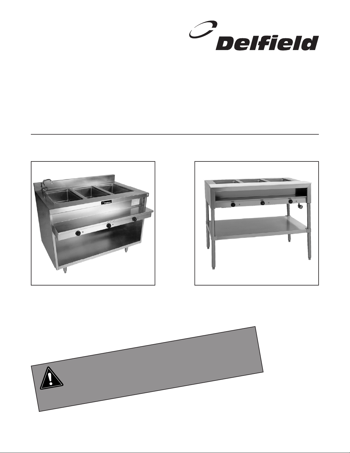
F14 and 48000 SERIES
CAUTION
Service and Installation Manual
Please read this manual completely before attempting to install or operate this equipment! Notify carrier of damage! Inspect all
components immediately. See page 3.
Hot Food Tables
IMPORTANT INFORMATION
READ BEFORE USE
PLEASE SAVE THESE INSTRUCTIONS!
Effective May 2003
Page 2

F14 AND 48000 Series Service and Installation Manual
F14 AND 48000 Series Service and Installation Manual
3
For customer service, call (800) 733-8829, (800) 773-8821, Fax (989) 773-3210, www.deleld.com
CONTENTS
SERIAL# LOCATION..............................................................2
RECEIVING & INSPECTING ..................................................2
SPECIFICATIONS ..................................................................3
INSTALLATION
F14EW & F14EI (electric) ................................................3
48300 Series (electric) ....................................................3
F14GW (gas) ...................................................................5
OPERATION
F14EI & 48300 Series (electric) ......................................4
F14EW (electric) ..............................................................4
F14GW (gas) ...................................................................5
MAINTENANCE .....................................................................5
GAS BURNER ASSEMBLY: F14GW Series ............................6
DELFIELD FOOD WARMER (DFW) ASSEMBLIES
with thermostatic controls ..............................................7
with infinite control .........................................................8
REPLACEMENT PARTS LISTS ..............................................9
WIRING DIAGRAMS
F14EI & 48300 Series (electric) ....................................10
F14EW (electric) ............................................................11
STANDARD WARRANTY............................................... 13-14
AUTHORIZED PARTS DEPOTS............................(back cover)
SERIAL NUMBER LOCATION
The serial number on all 14 Series and 48000 Series hot
food tables is printed on the tag located on the plate shelf.
Always have the serial number of your unit available when
calling for parts or service. A complete list of authorized
Delfield parts depots is shown on the back cover of this
manual.
©2003 The Delfield Company. All rights reserved. Reproduction without
written permission is prohibited. “Delfield” is a registered trademark of The
Delfield Company.
RECEIVING AND INSPECTING THE EQUIPMENT
Even though most equipment is shipped crated, care should
be taken during unloading so the equipment is not damaged
while being moved into the building.
1. Visually inspect the exterior of the package and skid or
container. Any damage should be noted and reported
to the delivering carrier immediately.
2. If damaged, open and inspect the contents with the
carrier.
3. In the event that the exterior is not damaged, yet upon
opening, there is concealed damage to the equipment
notify the carrier. Notification should be made verbally
as well as in written form.
4. Request an inspection by the shipping company of the
damaged equipment. This should be done within 10
days from receipt of the equipment.
5. Check the lower portion of the unit to be sure legs or
casters are not bent.
6. Also open the compressor compartment housing and
visually inspect the refrigeration package. Be sure lines
are secure and base is still intact.
7. Freight carriers can supply the necessary damage forms
upon request.
8. Retain all crating material until an inspection has been
made or waived.
Uncrating the Equipment
First cut and remove the banding from around the crate.
Remove the front of the crate material, use of some tools will
be required. If the unit is on legs remove the top of the crate
and lift the unit off the skid. If the unit is on casters it can be
"rolled" off the skid.
2
For customer service, call (800) 733-8829, (800) 773-8821, Fax (989) 773-3210, www.deleld.com
Page 3
SPECIFICATIONS
F14 AND 48000 Series Service and Installation Manual
MODEL NUMBER OF AMPS SHIP
NUMBER OPENINGS 208/230 WEIGHT
Electric with individual wells — wet or dry operation
F14EI232 2 10.0/11.0 216 lbs/98 kg
F14EI348 3 15.0/16.0 296 lbs/134 kg
F14EI460 4 20.0/22.0 376 lbs/170 kg
F14EI572 5 24.0/27.0 456 lbs/207 kg
F14EI688 6 29.0/32.0 536 lbs/243 kg
Electrical connections are 208/230 volt, 60 cycle, single phase.
Each opening measures 11.87” x 19.87” (30.2cm x 50.5cm).
Electric with single tank — wet operation only
F14EW232 2 21.0/24.0 316 lbs/143 kg
F14EW348 3 21.0/24.0 440 lbs/199 kg
F14EW460 4 21.0/24.0 500 lbs/227 kg
F14EW572 5 42.0/48.0 560 lbs/254 kg
F14EW688 6 42.0/48.0 660 lbs/299 kg
Electrical connections are 120/240 volt, or optional 120/208 volt.
(120 volt circuit is required for the low water cutoff.)
MODEL NUMBER OF NUMBER OF SHIP
NUMBER OPENINGS* GAS BURNERS BTU WEIGHT
Gas with single tank — wet operation only
F14GW232 2 1 20000 256 lbs/116 kg
F14GW348 3 1 20000 326 lbs/148 kg
F14GW460 4 1 20000 396 lbs/180 kg
F14GW572 5 2 40000 456 lbs/207 kg
F14GW688 6 2 40000 536 lbs/243 kg
*Each opening measures 11.87” x 19.87” (30.2cm x 50.5cm).
MODEL SHIP
NUMBER VOLTAGE AMPS WEIGHT
Electric with individual wells — wet or dry operation
48334 120/208 17.0/11.0 179 lbs/81 kg
48348 208/230 15.0/16.0 252 lbs/114 kg
48362 208/230 20.0/22.0 326 lbs/148 kg
48376 208/230 24.0/27.0 400 lbs/181 kg
INSTALLATION: F14EI & F14EW SERIES (ELECTRIC)
Installation should only be done by personnel
certified and licensed to install and maintain
electrical appliances.
Location
Do not install the hot food table near any combustible objects or
surfaces affected by heat or moisture.
Leveling
This unit must be level, both front and back and left to right, in
order to maintain an equal water depth throughout the wells.
Plumbing
Hot water supply connection is provided 36” (91.4cm) above the
floor, 3.12” (7.9cm) from the front left end at the rear of the unit.
You must supply the required 1/2” NPT connection.
A waste connection is provided 25” (63.5cm) above the floor, 7.5”
(19cm) from the right end. You must supply the required 1” NPT
connection.
Electrical connection
INSTALLATION: 48300 SERIES (ELECTRIC)
Installation should only be done by personnel
certified and licensed to install and maintain
electrical appliances.
Location
Do not install the hot food table near any combustible objects or
surfaces affected by heat or moisture.
Leveling
This unit must be level, both front and back and left to right, in
order to maintain an equal water depth throughout the wells.
Plumbing
A waste connection is provided 26.5” (67.3cm) above the floor,
5.25” (13.3cm) from the right end. You must supply the required
1” NPT connection.
Electrical connection
Connections must be made in accordance with all
applicable local codes and/or the National Electrical
Code. Refer to the wiring diagrams on page 10.
Connections must be made in accordance with all
applicable local codes and/or the National Electrical
Code. Refer to the wiring diagrams on page 10.
For customer service, call (800) 733-8829, (800) 773-8821, Fax (989) 773-3210, www.deleld.com
3
Page 4
F14 AND 48000 Series Service and Installation Manual
F14 AND 48000 Series Service and Installation Manual
5
For customer service, call (800) 733-8829, (800) 773-8821, Fax (989) 773-3210, www.deleld.com
OPERATION: F14EI & 48300 SERIES (ELECTRIC)
Before the unit is used the first time for serving, turn the
temperature knob to “10” and heat the well for 20 to 30 minutes.
Do not be alarmed if smoke appears; this preheat should burn off
any residue or dust on the heating element.
When using thick sauces always operate the hot food well filled
with water. This will provide a more uniform temperature for the
sauce.
Steam can cause serious burns. Always wear some
type of protective covering on your hands and arms
when removing lids or pans from the unit. Lift the lid
or pan in a way that will direct escaping steam away
from your face and body.
Never place food directly into the well. Always use
pans.
Although these models may be operated either with or without
water in the wells, wet operation is recommended.
Always place covers on pans when not serving to prevent food
from drying out and to reduce your operating cost.
For most efficient operation when empty, keep covered insets in
each well during preheating and when the well is not in use.
Do not put food down drain.
Wet operation
1) Fill food well with two inches of water. For quicker
pre-heating, use hot water to fill the well.
2) Turn the control to “HIGH” and pre-heat the warmer
for 30 minutes.
3) After pre-heating, set the control to your desired
serving temperature.
Dry operation
1) Pre-heat the well on “HIGH” for approximately 15
minutes.
2) After pre-heating, set the control to your desired
serving temperature.
Only 6” (15.2cm) deep insets should be used with a dry food well.
When operated dry, the bottom of the food well will discolor. A
mild abrasive cleaner is recommended to clean this discoloration.
Temperature
Water in wells . . . . . . . . . . . . . . . . . . . . . . . . . . . . 160°F to 180°F
Product in pans . . . . . . . . . . . . . . . . . . . . . . . . . . . 140°F to 160°F
OPERATION: F14EW SERIES (ELECTRIC)
These units must be operated with water in the well. If operated
dry, a low water safety switch will interrupt the electric supply
to the heater to prevent heater failure. If the low water safety
switch shuts off power, turn the control to the OFF position. If the
water level is below the heating element, allow the well to cool
completely, then refill with water. Reactivate the well by turning the
control ON and resetting to the previous temperature.
Continuous interruption of power due to a low water level may
disable the heater permanently. Pouring water on a hot heating
element will damage it.
Steam can cause serious burns. Always wear some
type of protective covering on your hands and arms
when removing lids or pans from the unit. Lift the lid
or pan in a way that will direct escaping steam away
from your face and body.
Never place food directly into the well. Always use
pans.
Always place covers on pans when not serving to
prevent food from drying out and to reduce your
operating cost.
For most efficient operation, when empty, keep covered insets in
each well during preheating and when the well is not in use.
Wet operation
Temperature
Water in wells . . . . . . . . . . . . . . . . . . . . . . . . . . . . 160°F to 180°F
Product in pans . . . . . . . . . . . . . . . . . . . . . . . . . . . 140°F to 160°F
1) Fill food well with four inches of water (heater must
be covered by water). For quicker pre-heating, use
hot water to fill the well.
2) Set the control to your desired serving temperature.
4
For customer service, call (800) 733-8829, (800) 773-8821, Fax (989) 773-3210, www.deleld.com
Page 5
OPERATION: F14GW SERIES (GAS)
F14 AND 48000 Series Service and Installation Manual
Gas connection
Only qualified and trained personnel should attempt
to connect the gas. Wear a face shield during this
procedure. Delfield is not responsible for injuries
resulting from attempts connect the gas.
You must supply the necessary connection. A pressure regulated,
1/2” FPT. 20,000 BTU gas supply is required. A gas regulator is
supplied installed.
Be sure the connection is made to maintain flow
through the safety valve in the direction indicated by
the arrow stamped on the valve case. See the gas
burner assembly diagram on page 6.
After installation, check for leaks using a soap solution. Mix some
water with dish or other soap and supply a small amount to the
connection. If bubbles appear, the connection is not correct and
must be reinstalled before operating the unit.
The pilot valve supplied is sized for use with natural
gas. If LP gas is to be used, the pilot fitting must be
changed from the standard .021” orifice to a .011”
orifice. This orifice is supplied in a plastic pouch
attached to the plate shelf.
Gas hot food tables must be operated with water in the well. Dry
operation of this unit will cause distortion of the well or other
serious damage.
Steam can cause serious burns. Always wear some
type of protective covering on your hands and arms
when removing lids or pans from the unit. Lift the lid
or pan in a way that will direct escaping steam away
from your face and body.
Lighting the pilot
Only qualified and trained personnel
should attempt to light the pilot. Wear
a face shield during this procedure.
Delfield is not responsible for injuries
resulting from attempts to light the pilot.
1) Open the gas valve supplying fuel to the hot food
table
2) Push down the reset button on the pilot valve,
which is located behind the control panel, and light
the pilot.
3) Continue to hold down the reset button for 30 to 45
seconds or until the pilot continues to burn when
the button is released.
4) During the reset cycle, gas will flow to both the
main and pilot burners.
5) If the pilot is not lit after steps 1-4 have been
completed, close the gas valve and wait for at least
5 minutes before attempting to light the pilot again.
This should allow any excess gas in the air around
the unit to dissipate. If you are using LP gas, wait
at least 15 minutes; any excess gas will “fall” to the
floor and will require more time to dissipate.
Filling the well and pre-heating
1) With the drain cock closed, fill the well until
approximately a four inch depth is obtained. More
water may be required if shallow depth pans are
used. Always pour water in the well before preheating. For quicker pre-heating use hot water to fill
the well.
2) Turn the gas control knob 1/4 turn counterclockwise
and wait for the water to preheat. Then set the
control to your desired serving temperature.
Never place food directly into the empty well, always
use pans. Never operate burners without water in the
well.
Always place covers on pans when not serving to prevent food
from drying out and to reduce your operating cost.
For most efficient operation, when empty, keep covered insets in
each well during preheating and when the well is not in use.
MAINTENANCE
The exterior can be cleaned using mild soap and warm water. If
this is not sufficient try ammonia and water or a non-abrasive
liquid cleaner. When cleaning the exterior, always rub with the
grain of the stainless steel to avoid marring the finish. Do not use
an abrasive cleaner because it will scratch the stainless steel. A
stainless steel cleaner or polish may be used to eliminate water
spotting and fingerprints and bring out the finish of the exterior.
The interior of the food wells should be cleaned daily with a
For customer service, call (800) 733-8829, (800) 773-8821, Fax (989) 773-3210, www.deleld.com
Temperature
Water in wells 160°F to 180°F
Product in pans 140°F to 160°F
non-abrasive cleaner and non-abrasive pad. If necessary, a mild
abrasive may be used on the interior of the pans only. Hard water
stains and lime scaling may require a special cleaning product.
Never use steel wool.
Do not use a hose or pressure washer on these
units. The water will damage the electrical and
gas components.
5
Page 6

F14 AND 48000 Series Service and Installation Manual
F14 AND 48000 Series Service and Installation Manual
7
For customer service, call (800) 733-8829, (800) 773-8821, Fax (989) 773-3210, www.deleld.com
23
21
22
20
18
19
16
15
10
23
2
9
7
8
6
13
12
11
1
3
2
5
4
16
15
2
2
16
15
1
14
16
15
17
GAS BURNER ASSEMBLY: F14GW SERIES (SINGLE SHOWN)
NOTE: The same parts are used for the
double burner assembly
KEY QTY PART# DESCRIPTION
1 2 3547413 elbow 1/2” NPT
2 8 9321035 nut, 1/4-20
3 1 3547411 manifold nipple, 23”
4 1 3234205A gas burner assy
5 1 3547409 nipple, 3/4 x 12
6 1 3234341 thermocouple
7 1 3234342 pilot assembly
8 20 3547329 tubing, copper, 1/4 O.D. x .028
9 1 3547407 pipe, manifold, valve, 12”
10 1 3547408 cap, 1/2 NPT
11 2 3547234 nipple, 1/2” x 2”
12 1 3234022 regulator, natural gas
KEY QTY PART# DESCRIPTION
13 1 3234023 device, vent limiting, gas reg.
14 1 3547406 nipple, 1/2 x 6.5”
15 4 9321157 u-bolt, 1/4 - 20
16 8 9321059 washer, 1/4
17 1 3234343 valve, safety
18 1 3234205B chamber, air mixing
19 1 3234205C plate, air mixing
20 1 3547593 fitting, inlet, burner (natural)
21 1 3234205D cock, front handle
22 1 3234205E handle, valve
23 1 3547591 fitting, inlet burner (LP)
24 1 3547412 nipple, manifold 31.25” dbl bnr only
6
For customer service, call (800) 733-8829, (800) 773-8821, Fax (989) 773-3210, www.deleld.com
Page 7

F14 AND 48000 Series Service and Installation Manual
8.50
2.31 CLEAR
DRAIN
OPTIONAL
3
12
6
1
5
11
4
7
2
10
8
5.50
5.56
6
9
DELFIELD FOOD WELL (DFW) ASSEMBLY:
KEY PART NAME DELFIELD PART #
Complete assembly, 115V, thermostat w/drain XMK00100
Complete assembly, 115V, thermostat w/o drain XMK00101
Complete assembly, 208V, thermostat w/drain XMK00102
Complete assembly, 208V, thermostat w/o drain XMK00103
1 Deflector plate GMK00061
2 Bottom cover GMK00062
3 Food well, with drain 016-0014
Food well, without drain 016-0015
4 Screw 932-1353
5 Element, 115V 219-4006
Element, 208V 219-4007
6 Screws (6) 932-1379
WITH THERMOSTATIC CONTROL
THERMOSTATIC
CONTROL
7 Insulation 343-4663
8 Thermostat control knob 323-4556
9 Thermostat, 200-550F 219-4012
10 Pilot light, red, 115V 219-4190
Pilot light, amber, 230V 219-4095
11 Drain cover GMK00063
12 Screws (2) 932-1353
NOTE: If you need four or more component parts, you
must buy a complete assembly.
For customer service, call (800) 733-8829, (800) 773-8821, Fax (989) 773-3210, www.deleld.com
7
Page 8

F14 AND 48000 Series Service and Installation Manual
F14 AND 48000 Series Service and Installation Manual
9
For customer service, call (800) 733-8829, (800) 773-8821, Fax (989) 773-3210, www.deleld.com
8.50
2.31 CLEAR
DRAIN
OPTIONAL
3
11
8
6
1
5
9
10
4
7
2
12
14
13
DELFIELD FOOD WELL (DFW) ASSEMBLY:
WITH INFINITE CONTROL
INFINITE
CONTROL
KEY PART NAME DELFIELD PART #
Complete assembly, 115V, infinite w/drain XMK00104
Complete assembly, 115V, infinite w/o drain XMK00105
Complete assembly, 208V, infinite w/drain XMK00068
Complete assembly, 208V, infinite w/o drain XMK00106
1 Deflector plate GMK00061
2 Bottom cover GMK00062
3 Food well, with drain 016-0014
Food well, without drain 016-0015
4 Screw 932-1353
5 Element, 115V 219-4006
Element, 208V 219-4007
6 Screws (2) 932-1379
7 Insulation 343-4663
8 Thermostat non-adjustable 219-4335
9 Screw 932-1007
10 Drain cover GMK00063
11 Screws (2) 932-1007
12 Infinite control, 120V 219-4107
Infinite control, 230V 219-4110
13 Infinite control knob 323-4557
14 Pilot light, red, 115V 219-4190
Pilot light, amber, 230V 219-4095
NOTE: If you need four or more component parts, you
must buy a complete assembly.
8
For customer service, call (800) 733-8829, (800) 773-8821, Fax (989) 773-3210, www.deleld.com
Page 9

MISCELLANEOUS PARTS LISTS
F14 AND 48000 Series Service and Installation Manual
F14EI Series (electric)
PART NAME DELFIELD PART #
Faucet . . . . . . . . . . . . . . . . . . . . . . . . . . . . . . . . . . . . 323-4075
Food well assembly . . . . . . . . . . . . . . . . . . . . . . . . see pgs. 7-8
Gate valve 1/2” . . . . . . . . . . . . . . . . . . . . . . . . . . . . . 354-7486
Legs, 6” w/mounting plate . . . . . . . . . . . . . . . . . . . . 323-4645
F14EW Series (electric)
PART NAME DELFIELD PART #
Brass drain . . . . . . . . . . . . . . . . . . . . . . . . . . . . . . . . 323-4065
Contactor, relay 30 amp, 120V . . . . . . . . . . . . . . . . . 219-4185
Faucet . . . . . . . . . . . . . . . . . . . . . . . . . . . . . . . . . . . . 323-4075
Float switch . . . . . . . . . . . . . . . . . . . . . . . . . . . . . . . . 219-4156
Gate valve, 1” . . . . . . . . . . . . . . . . . . . . . . . . . . . . . . 354-7487
Knob, thermostatic control . . . . . . . . . . . . . . . . . . . . 323-4556
Legs, 6” w/mounting plate . . . . . . . . . . . . . . . . . . . . 323-4645
Light, pilot, 250V, amber . . . . . . . . . . . . . . . . . . . . . . 219-4095
Relay, socket, KU12 . . . . . . . . . . . . . . . . . . . . . . . . . 219-4133
Relay, 8501, KU12 . . . . . . . . . . . . . . . . . . . . . . . . . . 219-4132
Immersion heater 5KW, 240V,
12.0 amps 3-phase . . . . . . . . . . . . . . . . . . . . . . . . . . 219-3972
Immersion heater 5KW, 208V,
24.0 amps, 1-phase . . . . . . . . . . . . . . . . . . . . . . . . . 219-3973
Immersion heater 5KW, 240V
20.8 amps, 1-phase . . . . . . . . . . . . . . . . . . . . . . . . 219-3974
Immersion heater 5KW, 208V,
13.9 amps, 3-phase . . . . . . . . . . . . . . . . . . . . . . . . . 219-3975
Thermostat . . . . . . . . . . . . . . . . . . . . . . . . . . . . . . . . 219-4202
Gas burner assembly . . . . . . . . . . . . . . . . . . . . . . . see page 6
48300 Series (electric)
PART NAME DELFIELD PART #
Bullet feet (4) . . . . . . . . . . . . . . . . . . . . . . . . . . . . . . . 323-4224
Casters . . . . . . . . . . . . . . . . . . . . . . . . . . . . . . . . . . . 323-4406
Leg . . . . . . . . . . . . . . . . . . . . . . . . . . . . . . . . . . . . . . . 323-4645
Cutting board pin cap . . . . . . . . . . . . . . . . . . . . . . . . 170-1000
Cutting board pin screw . . . . . . . . . . . . . . . . . . . . . . 932-1060
Brass cutting board hinge pin . . . . . . . . . . . . . . . . . . 323-4360
Food well assembly . . . . . . . . . . . . . . . . . . . . . . . . see pgs. 7-8
Gate valve, 1/2” . . . . . . . . . . . . . . . . . . . . . . . . . . . . . 354-7486
Polyethlene board, model 48334 . . . . . . . . . . . . . . . 130-1396
Polyethlene board, model 48348 . . . . . . . . . . . . . . . 130-1397
Polyethlene board, model 48362 . . . . . . . . . . . . . . . 130-1398
Polyethlene board, model 48376 . . . . . . . . . . . . . . . 130-1399
F14GW Series (gas)
PART NAME DELFIELD PART #
Faucet . . . . . . . . . . . . . . . . . . . . . . . . . . . . . . . . . . . . 323-4075
Gate valve 1” . . . . . . . . . . . . . . . . . . . . . . . . . . . . . . . 354-7487
Legs, 6” w/mounting plate . . . . . . . . . . . . . . . . . . . . 323-4645
For customer service, call (800) 733-8829, (800) 773-8821, Fax (989) 773-3210, www.deleld.com
9
Page 10

F14 AND 48000 Series Service and Installation Manual
F14 AND 48000 Series Service and Installation Manual
11
For customer service, call (800) 733-8829, (800) 773-8821, Fax (989) 773-3210, www.deleld.com
L1 G
HEATER 1
L2
CONTROL
PILOT LIGHT
"INFINITE"
HEATER 2
PILOT LIGHT
HEATER 3
PILOT LIGHT
HEATER 4
PILOT LIGHT
HEATER 5
PILOT LIGHT
HEATER 6
PILOT LIGHT
120 or 208-240V
SINGLE PHASE MODELS
L1 G L3
208-240V 3 PHASE MODELS
HEATER 1
L2
CONTROL
PILOT LIGHT
"INFINITE"
HEATER 4
PILOT LIGHT
HEATER 2
PILOT LIGHT
HEATER 5
PILOT LIGHT
HEATER 6
PILOT LIGHT
CONTROL
"INFINITE"
HEATER 3
PILOT LIGHT
1000 W - 120V
or 1000/1222 W -
208/230 V
heating element
pilot light (furnished)
infinite control
with “OFF” position
to additional
food warmers
line wires
P
L1
L2
H1
H2
(NEUTRAL ON 120V MODELS)
WIRING DIAGRAMS: F14EI AND 48300 SERIES
10
For customer service, call (800) 733-8829, (800) 773-8821, Fax (989) 773-3210, www.deleld.com
Page 11

F14 AND 48000 Series Service and Installation Manual
WIRING DIAGRAMS: F14EW SERIES
120-208 OR 120-240 VOLT SINGLE PHASE SUPPLY
Single Phase
TEMPERATURE
CONTROL
LOW WATER LIGHT
SWITCH
CONTROL BOARD
HEAT
FILL
H
N
BLUE
BLACK
WATER LEVEL
XL HI C
WATER FILL
SOLENOID
WHITE
WHITE-NEUTRAL
FLOAT
OPTIONAL
L2-BLACK L1-RED GREEN-GROUND TO CASE
C2
POWER RELAY
120VAC COIL
RED
BLACK
RED
THERMAL
OVERLOAD
ON HEATER
BLACK
PILOT LIGHT
IMMERSION
219-4095
HEATER
Three Phase
BLACK
TEMPERATURE
CONTROL
LOW WATER LIGHT
HEAT
FILL
H
N
BLUE
WHITE-NEUTRAL
SWITCH
WATER LEVEL
CONTROL BOARD
XL HI C
WATER FILL
SOLENOID
WHITE
120-208 OR 120-240 VOLT THREE PHASE SUPPLY
L2-BLACK
L1-RED
L3-BLUE
RED
C3
L3-BLUE
L2-BLACK
RED
FLOAT
OPTIONAL
WHITE
L1-RED
PILOT LIGHT
219-4095
THREE PHASE
IMMERSION
HEATER
GREEN-GROUND TO CASE
POWER RELAY
120VAC COIL
RED
THERMAL
OVERLOAD
ON HEATER
For customer service, call (800) 733-8829, (800) 773-8821, Fax (989) 773-3210, www.deleld.com
11
Page 12

F14 AND 48000 Series Service and Installation Manual
F14 AND 48000 Series Service and Installation Manual
13
For customer service, call (800) 733-8829, (800) 773-8821, Fax (989) 773-3210, www.deleld.com
STANDARD LABOR GUIDELINES TO REPAIR OR REPLACE PARTS ON DELFIELD EQUIPMENT
Advice and recommendations given by Delfield Service Technicians do not constitute or guarantee any special coverage.
• A maximum of 1-hour is allowed to diagnose a defective component.
• A maximum of 1-hour is allowed for retrieval of parts not in stock.
• A maximum travel distance of 100 miles round trip and 2-hours will be reimbursed.
• Overtime, installation/start-up, normal control adjustments, general maintenance, glass breakage, freight damage, and/or
correcting and end-user installation error will not be reimbursed under warranty unless pre-approved with a Service Work
Authorization from Delfield. You must submit the number with the service claim.
LABOR OF 1-HOUR IS ALLOWED TO REPLACE:
• Thermostat • Contactor/Relay
• Infinite Switch • Transformer
• Door Jamb Switch • Evaporator/Condenser Fan Motor and Blade
• Solenoid Coil • Circulating Fan Motor and Blade
• Hi-limit/Thermal Protector Switch • Microprocessor Control
• Fan Delay/Defrost Termination Switch • Water Level Sensor/Probe
• Compressor Start Components and Overload Protector • Door Hinges, Locks, and Gaskets
• Defrost Timer • Condensate Element
• Thermometer • Springs/Lowerator
• Gear Box
LABOR OF 2 HOURS TO REPLACE:
• Drawer Tracks/Cartridges • Defrost Element
• Pressure Control • Heating Element
• Solenoid Valve • Locate/Repair Leak
LABOR OF 3 HOURS TO REPLACE:
• EPR or CPR Valve • Condenser or Evaporator Coil
• Expansion Valve
LABOR OF 4 HOURS TO REPLACE
• Compressor
This includes recovery of refrigerant and leak check.
$35.00 maximum reimbursement for refrigerant recovery (includes recovery machine, pump, torch, oil, flux, minor fittings,
solder, brazing rod, nitrogen, or similar fees.)
REFRIGERANTS
• R22 A maximum of $4.00/lb. or 25¢/oz. will be reimbursed.
• R134A A maximum of $5.00/lb. or 31¢/oz. will be reimbursed.
• R404A A maximum of $12.00/lb. or 75¢/oz. will be reimbursed.
12
For customer service, call (800) 733-8829, (800) 773-8821, Fax (989) 773-3210, www.deleld.com
Page 13

F14 AND 48000 Series Service and Installation Manual
STANDARD ONE YEAR WARRANTY (One year parts, 90 days labor.)
The Deleld Company (“Deleld”) warrants to the Original Purchaser
of the Deleld product (herein called the “Unit”) that such Unit, and all
parts thereof, will be free from defects in material and workmanship
under normal use and service for a period of one (1) year from
the date of shipment of the Unit to the Original Purchaser or, if the
Original Purchaser returns the warranty card completely lled out
including the date of installation within thirty (30) days of receipt
of the Unit, one (1) year from the date of installation. During this
one year warranty period, Deleld will repair or replace any defective
part or portion there of returned to Deleld by the Original Purchaser
which Deleld determines was defective due to faulty material or
workmanship. The Original purchaser will pay all labor, crating, freight
and related costs incurred in the removal of the Unit of defective
component and shipment to Deleld, except that during a period of
either ninety (90) days from the date of shipment of the Unit to the
Original Purchaser or, if the Original Purchaser returns the warranty
card completely lled out including the date of installation within thirty
(30) days of receipt of the Unit, ninety (90) days from the date of
installation Deleld will pay all related labor costs. Deleld will pay the
return costs if the Unit or part thereof was defective.
The term “Original Purchaser” as used herein means that person, rm,
association, or corporation for whom the Unit was originally installed.
This warranty does not apply to any Unit or part thereof that has
been subjected to misuse, neglect, alteration, or accident, such as
accidental damage to the exterior nish, operated contrary to the
recommendations specied by Deleld; or repaired or altered by anyone
other than Deleld in any way so as to, in Deleld’s sole judgement,
affect its quality or efciency. This warranty does not apply to any Unit
that has been moved from the location where it was originally installed.
This warranty also does not cover the refrigerator drier or the light
bulbs used in the Unit. The warranty is subject to the user’s normal
maintenance and care responsibility as set forth in the Service and
Installation Manual, such as cleaning the condenser coil, and is in
lieu of all other obligations of Deleld. Deleld neither assumes, nor
authorizes any other person to assume for Deleld, any other liability
in connection with Deleld’s products.
being issued after the part has been received and inspected at Deleld’s
plant and determined by Deleld to be within this warranty.
Under no condition does this warranty give the Original Purchaser the
right to replace the defective Unit with a complete Unit of the same
manufacturer or of another make. Unless authorized by Deleld in
writing, this warranty does not permit the replacement of any part,
including the motor-compressor, to be made with the part of another
make or manufacturer.
No claims can be made under this warranty for spoilage of any
products for any reason, including system failure.
The installation contractor shall be responsible for building access,
entrance and eld conditions to insure sufcient clearance to allow
any hood(s), vent(s), or Unit(s) if necessary, to be brought into the
building. Deleld will not be responsible for structural changes
or damages incurred during installation of the Unit or any exhaust
system.
Deleld shall not be liable in any manner for any default or delay in
performance hereunder caused by or resulting from any contingency
beyond Deleld’s control, including, but not limited to, war,
governmental restrictions or restraints, strike, lockouts, injunctions,
re, ood, acts of nature, short or reduced supply of raw materials, or
discontinuance of the parts by the original part manufacturer.
Except as provided in any Additional Four Year Protection Plan,
if applicable, and the Service Labor Contract, if applicable, the
foregoing is exclusive and in lieu of all other warranties, whether
written or oral, express or implied. This warranty supersedes
and excludes any prior oral or written representations or
warranties. Deleld expressly disclaims any implied warranties
of merchantability, tness for a particular purpose of compliance
with any law, treaty, rule or regulation relating to the discharge of
substances into the environment. The sole and exclusive remedies
of any person relating to the Unit, and the full liability of Deleld
for any breach of this warranty, will be as provided in this warranty.
Removal or defacement of the original Serial Number or Model Number
from any Unit shall be deemed to release Deleld from all obligations
hereunder or any other obligations, express or implied.
Parts furnished by suppliers to Deleld are guaranteed by Deleld only
to the extent of the original manufacturer’s express warranty to Deleld.
Failure of the Original Purchaser to receive such manufacturer’s express
warranty to Deleld. Failure of the Original Purchaser to receive such
manufacturers warranty shall in no way create any warranty, expressed
or implied, or any other obligation or liability on Deleld’s part in respect
thereof.
IF THE CUSTOMER IS USING A PART THAT RESULTS IN A VOIDED
WARRANTY AND A DELFIELD AUTHORIZED REPRESENTATIVE
TRAVELS TO THE INSTALLATION ADDRESS TO PERFORM WARRANTY
SERVICE, THE SERVICE REPRESENTATIVE WILL ADVISE CUSTOMER
THE WARRANTY IS VOID. SUCH SERVICE CALLS WILL BE BILLED
TO CUSTOMER AT THE AUTHORIZED SERVICE CENTER’S THEN
APPLICABLE TIME AND MATERIALS RATES. CONSIDER: CUSTOMER
MAY INITIATE A SERVICE AGREEMENT WITHOUT PARTS COVERAGE.
If shipment of a replacement part is requested prior to the arrival in the
Deleld factory of the part claimed to be defective, the Original Purchaser
must accept delivery of the replacement part of a C.O.D. basis, with credit
For customer service, call (800) 733-8829, (800) 773-8821, Fax (989) 773-3210, www.deleld.com
Other than this Deleld Standard One Year Limited Warranty, any
applicable Deleld Additional Four Year Protection Plan or applicable
Deleld Service Labor Contract, the Original Purchaser agrees and
acknowledges that no other warranties are offered or provided in
connection with or for the unit or any other part thereof.
In no event will Deleld be liable for special, incidental or
consequential damages, or for damages in the nature of penalties.
IF DURING THE WARRANTY PERIOD, CUSTOMER USES A PART
FOR THIS DELFIELD EQUIPMENT OTHER THAN AN UNMODIFIED
NEW OR RECYCLED PART PURCHASED DIRECTLY FROM DELFIELD
OR ANY OF ITS AUTHORIZED SERVICE CENTERS AND/OR THE PART
BEING USED IS MODIFIED FROM ITS ORIGINAL CONFIGURATION,
THIS WARRANTY WILL BE VOID. FURTHER, DELFIELD AND ITS
AFFILIATES WILL NOT BE LIABLE FOR ANY CLAIMS DAMAGES
OR EXPENSES INCURRED BY THE CUSTOMER WHICH ARISE
DIRECTLY OR INDIRECTLY, IN WHOLE OR IN PART, DUE TO THE
INSTALLATION OF ANY MODIFIED PART AND/OR PART RECEIVED
FROM AN UNAUTHORIZED SERVICE CENTER. If the warranty
becomes void, Customer may purchase from Deleld, if available,
a Service Agreement or service at the then current time and
materials rate.
For more information on Deleld warranty’s log on and check out the
service section of our web site at www.deleld.com.
13
Page 14

F14 AND 48000 Series Service and Installation Manual
F14 AND 48000 Series Service and Installation Manual
15
For customer service, call (800) 733-8829, (800) 773-8821, Fax (989) 773-3210, www.deleld.com
ADDITIONAL FOUR YEAR PROTECTION PLAN (for Motor-Compressor only)
Installation
Deleld Model# Serial # Date
General Conditions
Deleld shall not be liable in any manner for any default or delay
in performance hereunder caused by or resulting from any
contingency beyond Deleld’s control, including, but not limited
In addition to the Standard One Year Warranty on the MotorCompressor contained in the above listed Deleld product (the
“Unit”), The Deleld Company (“Deleld”) also agrees to repair, or
exchange with similar or interchangeable parts in design and capacity
at Deleld’s option, the defective Motor-Compressor contained in the
Unit (the “Motor-Compressor), or any part thereof, for the Original
Purchaser only, at any time during the four (4) years following the
initial one (1) year period commencing on the date of installation for
the Original Purchaser. Failure of the Original Purchaser to register
the registration card containing the Original Purchasers name,
address, date of installation, model number and serial number of
the Unit containing the Motor-Compressor within 30 days from the
date of installation shall void this warranty. This additional warranty
is only available if the Motor-Compressor is inoperative due to defects
in material or factory workmanship, as determined by Deleld in
its sole judgement and discretion. The Original Purchaser shall be
responsible for returning the defective Motor-Compressor to Deleld
prepaid, F.O.B. at the address shown on the back cover of this manual.
The term “Original Purchaser” as used herein means that person, rm,
association, or corporation for whom the Unit was originally installed.
The term “Motor-Compressor” as used herein does not include unit
base, air or water cooled condenser, receiver, electrical accessories
such as relay, capacitors, refrigerant controls, or condenser fan/motor
assembly. This warranty does not cover labor charges incidental to
the replacement of parts. This warranty further does not include
any equipment to which said condensing unit is connected, such as
cooling coils, temperature controls or refrigerant metering devices.
This warranty shall be void if the Motor-Compressor, in Deleld’s
sole judgement, has been subjected to misuse, neglect, alteration
or accident, operated contrary to the recommendations specied
by the Unit manufacturer, repaired or altered by anyone other than
Deleld in any way so as, in Deleld’s sole judgment, to affect its
quality or efciency or if the serial number has been altered, defaced
or removed. This Warranty does not apply to a Motor-Compressor in
any Unit that has been moved from the location where it was originally
installed. The addition of methyl chloride to the condensing unit or
refrigeration system shall void this warranty.
to, war, governmental restrictions or restraints, strike, lockouts,
injunctions, re, ood, acts of nature, short or reduced supply
of raw materials, or discontinuance of any part or the Motor-
Compressor by the unit manufacturer.
Replacement of a defective Motor-Compressor is limited to one (1)
Motor-Compressor by us during the four (4) year period. Deleld
shall replace the Motor-Compressor at no charge.
This warranty does not give the Original Purchaser of the Motor-
Compressor the right to purchase a complete replacement Motor-
Compressor of the same make or of another make. It further does
not permit the replacement to be made with a Motor-Compressor
of another kind unless authorized by Deleld. In the event Deleld
authorizes the Original Purchaser to purchase a replacement
Motor-Compressor locally, only the wholesale cost of the Motor-
Compressor is refundable.
Expressly excluded from this warranty are damages resulting from
spoilage of goods.
Except as provided in any applicable Standard One Year Limited
Warranty or applicable Service Labor Contract, the foregoing
is exclusive and in lieu of all other warranties, whether written
or oral, express or implied. This Warranty supersedes and
excludes any prior oral or written representations or warranties.
Deleld expressly disclaims any implied warranties of
merchantability, tness for a particular purpose or compliance
with any law, treaty, rule or regulation relating to the Motor-
Compressor, and the full liability of Deleld for any breach of this
warranty, will be as provided in this warranty.
Other than any applicable Deleld Standard One year Limited
Warranty, this Deleld Additional Four Year Protection Plan and any
applicable Deleld Service Labor Contract, the Original Purchaser
agrees and acknowledges that no other warranties are offered or
provided in connection with or for the Motor-Compressor or any
part thereof.
In no event will Deleld be liable for special, incidental or
consequential damages, or for damages in the nature of penalties.
14
For customer service, call (800) 733-8829, (800) 773-8821, Fax (989) 773-3210, www.deleld.com
Page 15

NOTES:
F14 AND 48000 Series Service and Installation Manual
For customer service, call (800) 733-8829, (800) 773-8821, Fax (989) 773-3210, www.deleld.com
15
Page 16

980 S. Isabella Rd., Mt. Pleasant, MI 48804-0470, U.S.A. • (989) 773-7981 or (800) 733-8821 • Fax (800) 669-0619 • www.delfield.com
Delfield reserves the right to make changes in design or specifications without prior notice. 2003 The Delfield Company. All rights reserved. Printed in the U.S.A.
1336 Main Street
Buffalo, NY 14209
800.722.1252
716.884.7425
716. 884.0410 FAX
serves: CT, DC, DE, MA, MD, ME,
NH, NJ, NY, PA, RI, VA, VT, WV
3) Appliance Installation Service
15024 Staff Court
Gardena, CA 90248
1.800.531.1111
1.800.782.5747
Email: orders@pacparts.com
www.pacparts.com
serves: AZ, CA, HI, NV, OR
4) Pacific Coast Parts
2916 Sidco Drive
Nashville, TN 37204
615.726.0351
800.737.0351
615.259.4100 FAX
serves: TN, AL
14) T.M.A.
14450 Ewing Ave S. #100
Burnsville, MN 55306
800.422.2823
952.894.4427
952.894.2164 FAX
serves: IA, MN, MT, ND, SD, WI
5) Contract Ice
3909 St. Timothy Lane
St. Ann, MO 63074
800.972.7670
314.427.7477
314. 427.8190 FAX
serves: AR, IA, IL, KS,
KY, MO, NE, OK, TX, NM, LA
6) E.M.C.O. Sales & Distributors
2920 N.W. 109th Avenue
Miami, FL 33172
305 994.9994
305.994.9992 FAX
International parts depot
9) Global Parts and Supplies
2120 Solona St.
PO Box 14009
Fort Worth, TX 76117-0009
1.800.433.1804 toll free
1.800.272.7358 fax
serves: AR, LA, NM, OK, TX
7) Stove Parts Supply/GCS Service
9923 S.W. 178th St.
Vashon, WA 98070
888.872.2465
206-463-1772
206.463.4431 FAX
serves: AK, HI, ID, MT, OR, WA
12) Performance Refrigeration Parts
2200 Norcross Parkway, Suite 210
Atlanta, GA 30071
800.235.6516
770.446.6177
770.446.3157 FAX
serves: FL, GA, MS, NC, SC, VA
13) Southeastern Restaurant Services
1816 West 26th Street
Erie, PA 16508-1149
800.332.3732
814.456.3732
814.452.4843 FAX
serves: MD, NJ, OH, PA, VA, WV
2) A.I.S. Commercial Parts & Service
1177 Kamato Road
Mississauga, Ontario L4W1X4
800.427.6668
800.361.7745 FAX
serves: Canada
8) Garland Group
980 South Isabella Road
Mt. Pleasant, MI 48858
800.733.8829
989.773.7981
989.773.3210 FAX
custom parts direct from Delfield
1) The Delfield Company
44792 Helm
Plymouth, MI 48170
888.828.4454
734.451.2043
734.451.3215 FAX
serves: MI, IN, WI, OH
11) MicroDine, Inc.
3000 S. Wyandot
Englewood, CO 80110
(800) 624-2117
(303) 7618861 FAX
serves: AZ, CO, KS, NE, NM, OK, UT, WY
10) Hawkins Commercial Appl. Serv.
NORTH
AMERICA
4
4
12
9
10
1
11
7
6
5
14
3
13
8
2
12
Delfield has 14 conveniently located Parts Depots to
ensure parts are handled promptly and accurately.
Delfield reserves the right to update or make changes
to this list without prior notice
Please call 1-800-733-8829 or check the web at www.delfield.com
for a list of the current Parts Depots.
AUTHORIZED PARTS DEPOTS
DM14_48 04/03
 Loading...