

Delfield F13WR General Manual
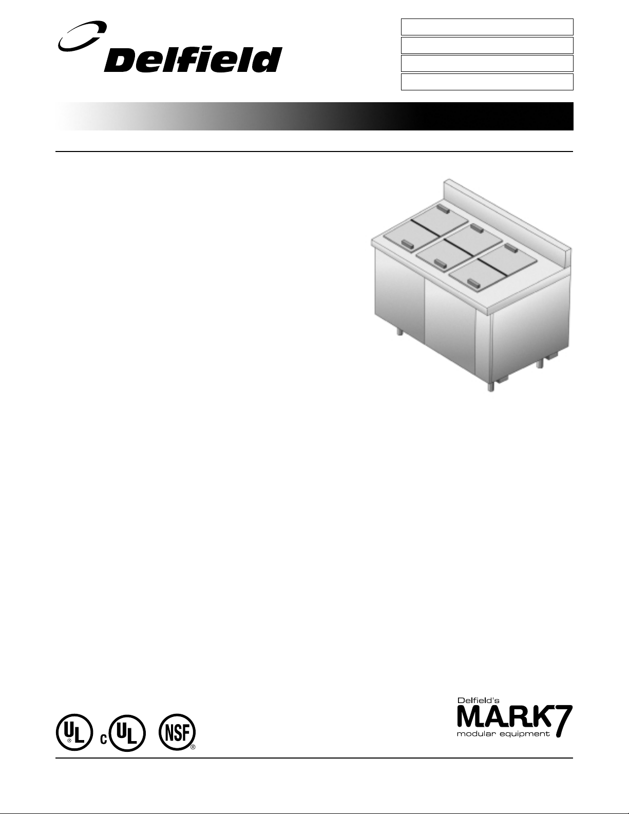
31.5” (80cm) Deep Remote Low Temp, Ice Cream Cabinets
Shor t Form Specif icat ions
To p is constructed of one-piece 16 -gauge stainless steel, with integral 2.12” (5.4
cm) square no sing on front and 4 ” (10 .1 c m) high by 2” (5.0 cm ) thick backsplash on rear. Top to be insulated and have raised rim opening(s) provided w ith
co ver. C over(s) are insulated, folding and removable.
Interior is co nstructed o f 2 2-gauge stainless steel. Liner is insulated with 2.5 ”
(6.4 cm ) fo amed-in-place polyurethane. Unit has a cold w all refrigeration system pro vided w ith adjustable expansion valve lo cated in the 6 ” (15 .2 cm)
mec hanical area at right end. Unit is designed to maintain 0°F (-18° C) to 5° F
(-15°C ).
Exte rior front has 22-gauge stainless steel front panel(s). Exterior ends are co n-
structed of 18 -gauge galvanized steel.
Electrical connections are 1 15 volt, 60 Hertz, single phase.
Unit must be hard w ired.
Unit is mounted on 6 .13” (15.6 cm) high adjustable stainless steel legs.
Refrigeration syste m com pone nts — HFC-40 4A.
PROJECT
ITEM #
QUANTITY DATE
APPROVAL
F13WR
Opt ional Accessor ies and modif icat ions
505 B Stainless steel back
906 A Stainless steel end
505 F Laminate facing
505 A Laminate back
906 E Laminate end
Mod el F13WR48
®
The Delfi eld Company, P.O. Box 470, M t Pleasant, MI 48804- 0470, U.S.A. • (800) 733- 8821 • Fax (800) 669- 0619 • w ww .del fi eld.com
Delfield reserves the right to make changes in design or specifications without prior notice. ©2001 The Delfield Company. All rights reserved. Printed in U.S.A.
Built to NSF7 standards.
F13WR
31.5” (80cm) Deep Remote Low Temp, Ice Cream Cabinets
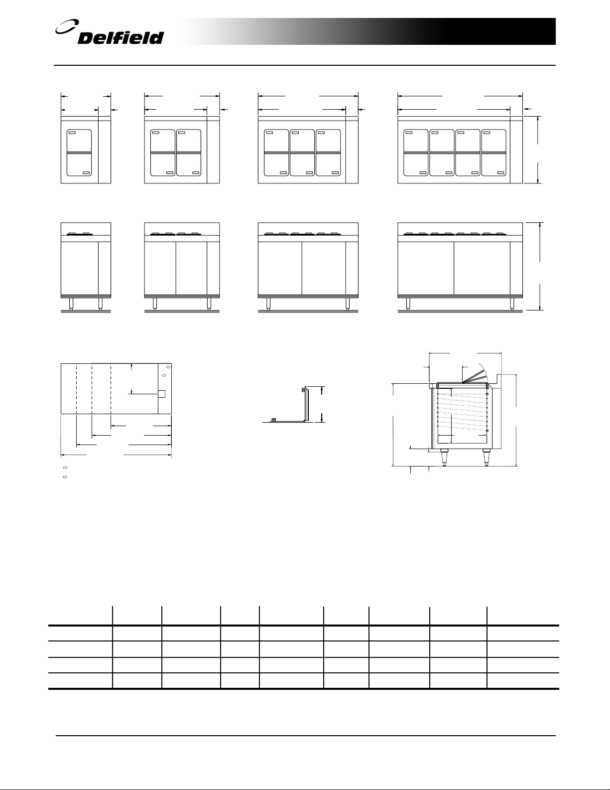
24" (61)
18"
(45.7)
PLAN VIEW
F13WR24
ELEVATION VIEW
F13WR24
60" (152.4)
V
Expansion valve 25" A.F.F.
R
Refrigeration lines 1/4" liquid, 3/8" suction
J= Junction box 25" A.F.F.
6"
(15.2)
(43.2)
36" (91.4)
48" (122)
30" (76.2)
PLAN VIEW
F13WR36
ELEVATION VIEW
F13WR36
R
17"
V
J
24" (61)
36" (91.4)
6"
(15.2)
48" (122)
42" (106.7)
PLAN VIEW
F13WR48
ELEVATION VIEW
F13WR48
12.5"
(31.8)
LID DETAIL
ALL MODELS
6"
(15.2)
36"
(91.4)
7.62"
(19.4)
60" (152.4)
54" (137.2)
PLAN VIEW
F13WR60
ELEVATION VIEW
F13WR60
31.5"
(80)
14.44"
(36.7cm)
23.75"
(60.3)
21.31"
(54.1)
6.12"
(15.6)
SIDE VIEW
ALL MODELS
40"
(101.6)
6"
(15.2)
31.5"
(80)
40"
(101.6)
Mechanical Dat a–St andar d Unit
MODEL GALLON NUMBER OF VOLTS/HERTZ BTU DESIGN EVAP. CAP. SHIP
NUMBER CAPACITY COVERS H.P. PHASE AMPS LOAD BTU/°TD WEIGHT
F1 3WR2 4
F1 3WR3 6
F1 3WR4 8
F1 3WR6 0
*Recommended
The Delfi eld Company, P.O. Box 470, M t Pleasant, MI 48804- 0470, U.S.A. • (800) 733- 8821 • Fax (800) 669- 0619 • w ww .del fi eld.com
Delfield reserves the right to make changes in design or specifications without prior notice. ©2001 The Delfield Company. All rights reserved. Printed in U.S.A.
12 2 1/3* 115/60/1 1.5 322 27 195 lbs/ 89 kg
24 4 1/3* 115/60/1 1.5 506 38 255 lbs/ 116 kg
36 6 1/3* 115/60/1 1.5 638 46 295 lbs/ 134 kg
48 8 1/3* 115/60/1 1.5 796 56 345 lbs/ 157 kg
DS13WR 02/01
 Loading...