


Delcam iQube 2010
Reference Manual

Copyright © 2 009 - 2010 Delc am plc. All rights reserved
Delcam plc has no control over the use made of the software described in
this manual and cannot acc ept responsi bility for any loss or damage
howsoever caused as a result of using the software. Users are advised that
all the results from the sof tware should be checked by a competent
person, in accordance with good quality control procedures.
The functionality and user interfac e in this manual is subject t o change
without not ice in future re visions of software.
The software described in this manual is furnished under licence
agreement and may be used or copied solely in accorda nce with the terms
of such licence.
Delcam plc grants permission for licensed users to print copies of t his
manual or portions of this manual for personal use only. Schools, c olleges
and universities that are licensed to use the software may make copies of
this manual or portions of this manual for students currently registered for
classes wher e the softwa re is used.
Acknowledgements
This documentation refer ences a number of registered tradem arks and
these are the property of their respective owners. F or example, Mic rosoft
and Windows are either registered trademarks or trade marks of Microsoft
Corporation in th e Uni te d Sta te s.
Scanner Name
The name of the scanner is the Delcam iQube. Any reference to iQube in
this documenta t io n ref ers to the Delcam iQube scanner and no o ther
product of a similar name.
Delcam iQube Version 201 0. Published on 16 June 2010

Delcam iQube 2010 Reference Manual Contents • i
Contents
Introduction 1
Compliance and Safety 2
Compliance .................................................................................................... 2
FCC ........................................................................................................ 2
WEEE .................................................................................................... 3
Technical Specifications ................................................................................ 5
Electrical Specifications ........................................................................ 5
Permissibl e Environmental Conditions ................................................. 5
Temperature Range ................................................................................ 5
Safety Precautions .......................................................................................... 6
Understand ing Warning Terms ............................................................. 6
Understanding Precaution Terms .......................................................... 7
Warnings ................................................................................................ 8
Cautions ................................................................................................. 9
Hardware installation and maintenance 10
Parts List ......................................................................................................11
Hardware Diagrams .....................................................................................12
Hardware diagram - legend .................................................................13
Setting up t he scanner ..................................................................................15
Remove the Cover ...............................................................................15
Electrical Connection ...........................................................................16
Network Connection ............................................................................18
Power-up the Scanner ..........................................................................19
Connecting to the Scanner ...................................................................21
Maintenance and Handling ..........................................................................27
Maintenance .........................................................................................27
Handling ...............................................................................................27

ii • Contents Delcam iQube 2010 Reference Manual
Software Installation 29
System Requirements ..................................................................................29
Installation ....................................................................................................30
Test ...............................................................................................................31
Using the Delcam Ortho ti c Insoles Software 32
Jobs Page ......................................................................................................33
Adding a Job ........................................................................................33
Deleting a Job ......................................................................................34
Scan Page .....................................................................................................35
Scan Model ..........................................................................................38
Changing the sca n set ti ngs ( per se ssi o n) .............................................39
Changing the Default Scan Settings ....................................................41
Scan mode ............................................................................................46
Export Page ..................................................................................................49
Scanning Procedures 51
Scanning a Foot ............................................................................................52
Scanner Setup (Foot) ...........................................................................52
Orientation and Location (Foot) ..........................................................54
Scan Settings (Foot) .............................................................................55
Scanning a Foam Box Impression ...............................................................56
Scanner Setup (Foam Box Impre ssion) ...............................................57
Orientation and Location (Foam Box Impression) ..............................59
Scan Settings (Foam Box Impression) ................................................60
Scanning a Cast ............................................................................................61
Scanner Setup (Cast) ............................................................................61
Orientation and Location (Cast) ..........................................................62
Scan Settings (Cast) .............................................................................63
Manufacturer Details 64
Index 65

Delcam iQube 2010 Reference Manual Introduction • 1
The Delcam iQube is a simple but powerful 3D scanner specifically
created for use in designing custom orthotic insoles. It is a versa tile tool
that produces high quality orthotics and insoles.
The iQube gives complete flexibility with respect to the scan model.
Scanning a foot, a cast or a foam box impression, produces a high quality
3D image in approximately 3 seconds, saving time and improving the
quality of the output.
Using technology developed for the Aerospace industry, the iQube
scanner obtains a high level of detail using laser and multi-camera
configuration to produce a highly accur ate full colour 3D image. The high
level of accuracy means that the custom orthotic is created corre ctly every
time, minim isin g the inc o nv en ie nce to cli e nt s.
The Delcam iQube allows the foot to be sc anned in several positions,
according to the needs of the patient.T he scanner ca n be set up for use in
full weight bearing (We ight On), semi-w eig ht bea ri ng a nd no n-weight
bearing (We ight Off) positions,
The scanner is lightweight and compact, making it fully portable; the
optional carrying case a llows you to transport it for use it at different
locations. Once you have scanned the item, Delcam OrthoModel software
lets you design and manufacture the custom insole. Alternatively, use the
scan data with your existing orthotic CADCAM software.
Introduction

2 • Compliance and Safety Delcam iQube 2010 Reference Manual
Full details of Complianc e, Technical Specifications and Safety
Precautions can be found in the followi ng sections:
Compliance ( see pag e 2).
Technical Specifications (see page 4).
Safety Precautions (see page 5).
Compliance
Refer to the following sections for compliance details:
FCC (see page 2)
WEEE (see page 3)
FCC
This equipment has been tested and found to comply with the limits for a
Class A digita l device, pursuant to par t 15 of the FCC R ules. These l imits
are designed to provide reasonable pro tection against harmful
interferenc e when the equipment is operated in a commercial
environment. This equipment generates, uses, and can radiate radio
frequency energy and, if not installed a nd used in accordance with the
instruction manual, may cause harmful interferenc e to radio
communications. Operation of this equipment in a residential area is
likely to cause harmful interference in which case the user will be
required to correct the inte rference at h is o wn ex pe nse.
Compliance and
Safety

Delcam iQube 2010 Reference Manual Compliance and Safety • 3
Also please n ote the following statement that is on a sticker adhered to
the base of the scanner body:
This device comp lie s wit h pa rt 15 o f the FCC Rule s. Ope r at io n is sub jec t
to the follow ing two conditions: (1) This device may n ot cause harmful
interference , and (2) this device must accept any interference received,
including interference that may cause undesired operation.
WEEE
WEEE stands for Waste Electrical and Electronic Equipment and
refers to a European Union (EU) directive regulating the disposal of
electrical or electronic equipment, including all components, subassemblies and consumables, which are part of the products at the t ime of
discarding.
European Directive 2002 /96/EC on Waste Electrical and Electronic
Equipment (the WEEE Direc t ive) stipulates tha t WEEE is now subject
to regulations designed to prevent the disposal of such waste an d to
encourage design and treatment measures to minim ize the amount of
waste that is place d int o the wa ste sy stem.
The purpose of this legislat io n is to pre se r v e, protec t a nd im pr ov e the
quality of t he environme nt, protect human health, and stimulate the
practical use of natural resources. Specifically, the WEEE Direc tive
requires that producers of electrical and electronic equipment be
responsible for the collection, reuse, recycling and treatment of WEEE
which the producer places on the EU ma rket after August 13, 2005.
As an importer of electrical and electr onic equipment (EEE), we have
endeavoure d to meet these environmental responsibilities for managing
WEEE. The following inf ormation is to educate our cus tomers about the
WEEE collec tion process.
In order to avoid any potential dissemination of hazardous substa nces into
the environment, the pro duct has been labelled with the WEEE symbol
(see below) in order to alert the end-user that it should be disposed of
within the pr oper waste management system. That system will recycle,
reuse, and dispose of mate rials from this product in an e nvironmentally
sound way.

4 • Compliance and Safety Delcam iQube 2010 Reference Manual
The symbol found on the De lcam product label, indicates that the product
meets the European Directive 2002/96/EC on Waste and Electronic
Equipment. This symbol, only applicable in European Union countries,
indicates that when this product reaches the end of its l ife it should not be
disposed of with normal household or municipal wast e, but in an
established waste stream for WEEE.
Each EU Member State country has established a system for the
collection, disposal, and recycling of WEEE. End-users in the EU should
contact their local waste administration system for collectio n instructions
concerning this product.

Delcam iQube 2010 Reference Manual Compliance and Safety • 5
Technical Specifications
Refer to the following sections for details of the Technical Specificati ons:
Electrical Specifications (see page 5)
Permissibl e Environmental Conditions (see page 5)
Temperature Range (see page 5)
Electrical Specifications
Voltage AC 100 V – 240 V / 120 W
Main supply volta ge flu ct ua ti o ns up to +/- 10% of the nominal
Permissible E nv ironment a l Con ditions
For Indoor Use Only
Maximum relative humidity 80% for temperatures up to 31 deg C
decreasing linearly to 50% relative humidity at 40 deg C
Vibration (55 to 2000Hz): <= 100ms/s*s EN 60 068-2-6
Shock (6ms): <= 1000ms/s*s
Altitude: Up to 2000m
Temperature Range
Storage Temperature: 5 deg C to 40 deg C
Ambient Temperature req uired for measuring operat ion: 20 deg C
+/- 10 deg C

6 • Compliance and Safety Delcam iQube 2010 Reference Manual
Safety Precautions
This equipment has been designed and tested to ensure reasonable
personal protection and protection of the surrounding area agai nst
damage. It has been supplied in safe condition. The user must observe the
precautions described in the following sections t o ensure safe operation
and to keep the equipment in safe condition.
If this equipment is used i n a manner not specified by the manufacturer,
the protect ion provided by this equipment may be impaired.
Different safety precautions are desc ribed in the following sections:
Understand ing Warning Terms (see page 6)
Understand ing Precautio n Terms (see page 6)
Warnings (see page 7)
Cautions (see page 9)
Understanding W arning Terms
The table below shows the level of injuries or damages that may occur
when the equipment is used incorrectly , without payin g attention to
descriptions of warnings or cautions.
Notation Description
DANGER
Indicates a h azardous situation, which can result
in death or serious inj ury.
WARNING
Indicates a p otentially hazardous situation,
which can re sult in death or serious injur y.
CAUTION
Indicates a p otentially hazardous situation,
which can re sult in minor or moderate injury or
damage to the equipment.

Delcam iQube 2010 Reference Manual Compliance and Safety • 7
Understanding Precaution T erms
Precautions that must be adhered to are s hown below:
Notation Description
Pay attention.
Do not undertake this action.
You must undertake this action..
Laser Safety Notice.

8 • Compliance and Safety Delcam iQube 2010 Reference Manual
Warnings
The following warnings are potentially hazardous situations that can
result in death or serious i njury.
Do not damage the power cable or plug. Using a damaged
power cable or power plug may cause an el ectric shock, shortcircuit, smoke or fire.
Do not damage, modify, f orcefully bend, twist, stretch, or
bind the power cable and power plug.
Do not put heat source close to the power c able or plug.
Do not place a h eavy object on the power cable or plug.
Clean dust off the power plug periodically. Any dust on
the plug may cause insulation failure as the result of absorbed
moisture. It may also res ult in smoke or a fire.
Disconnect the power plug and wipe it with a dry cloth.
Operate the unit at the specifie d volta ge .
This equipment must be operated within the AC supply voltage
range marked on the rear panel of the equ ipment and / or a tag
attached to the power cable. The frequency of the power supply
must be 50 or 60 Hz.
Operating at a volt ag e or fre que n cy , other tha n the o ne spe c if ied
may result i n smoke or a fire.
Nominal
Range
AC 100 V – 240 V
90 V – 260 V
Do not insert or pull out the power cable w ith a wet
hand
. Attempting this may cause an electric shock.
Do not use the instrument in an explosive
environment. Never use the equipment in rooms containing
flammable or volatile ga s or vapour. Fa ilure to observe this
warning may cause an explo sion or a fire.
Do not disassemble the equipme nt. Attempting this may
cause an electric shock or malfu nction of the e quipment.
Removal of panels will expose live parts. If any adjustment,
maintenance or repair is required, it must be carried out by
qualified service personnel who are awa re of the hazard involved.

Delcam iQube 2010 Reference Manual Compliance and Safety • 9
Laser light can damage your eyes. Do not stare directly
into the beam or look at it with optical in struments.
Maximum weight limit is 200kg. Do not exceed maximum
weight limit on the gl ass.
Do not jump on the glass.
Cautions
The following cautions highlight the potentially hazardous situations,
which could r esult in m inor or moderate injury or damage to the
equipment.
Use the specified fuse. Verify that the correct
fuse is installed before connecting the power. Failure
to do so could r esult in sm oke or a fire.
Do not use unauthor ise d fu se s.
Nominal
Fuse rating
AC 100 V – 240 V
3.14A 250V (T)
Do not use the equipment if it appears to be
broken. Using potentially faulty e quipment could
result in an electric shock, smoke or a fire.
Immediately turn off the equipm ent an d di sco nne c t
the power cable. Then contact the dealer or
representative from whom you purchased the
equipment..
This equipment uses a Class II la ser.
Class II laser products do n ot normally cause eye
injuries, but care must be taken as it ca n still be quite
hazardous due to glare and temporary flash blindnes s.
The human blink reflex occurs within 0.25 seconds of
exposure to the Class II laser beam, providing
adequate prot ect i on. You should not try to resist
the natural blink response by staring into the
Class II laser. This could result in damage to the
eye.

10 • Hardware installation and maintenanc e Delcam iQube 2010 Reference Manual
Details of the hardware, setup and maintenance are included in the
following sec ti ons :
Parts List (see page 10)
Hardware Diagrams (see page 12)
Setting up t he scanner (see page 14)
Maintenance and Handling (see page 26)
Hardware installation
and maintenance

Delcam iQube 2010 Reference Manual Hardware installation and maintenance • 11
Parts List
The following items are supplied:
Scanner
1 x Delcam iQube 3D Scanner.
1 x scanner cover.
1 x AC power cable (regional).
1 x network cable.
Software
1 x Custom Orthotic Insoles installation CD.
1 x software dongle .
Documentation
1 x User Manua l.
Foam Box Scan Aids.
45mm Foam Box Lifters (x4).
40mm Lifter Extensions (x2).
Maintenance Kit
Glass cleaner sachets.

12 • Hardware installation and maintenanc e Delcam iQube 2010 Reference Manual
Hardware Diagrams

Delcam iQube 2010 Reference Manual Hardware installation and maintenance • 13
Hardware diagram - legend
The following items are shown on the hardware diagrams:
Main Unit
1.
Scanner body.
2.
Tempered glas s scr ee n.
3.
Scan activation switch.
4.
Electrical pan el.
5.
AC power cable connection.
6.
Power switch.
7.
LAN cable connection
8.
USB 1 connec tion (DO NOT USE).
9.
USB 2 connec tion (DO NOT USE).
10.
Screen Release socket.
11.
End lifting handles.
12.
Side handle.
Lid
13. Lid.
14.
Lid clips (x4).
15.
Standing surfa ce.
16.
Support legs.

14 • Hardware installation and maintenanc e Delcam iQube 2010 Reference Manual
Auxiliary Items
17.
AC power cab le (Regional).
18.
Network cable .
19.
Custom Orthotic Insoles installation CD.
20.
Software dongle.
21.
45mm Foam Box Lifters (x4).
22.
40mm Lifter Extensions (x2).
23.
Glass cleaner sachets.

Delcam iQube 2010 Reference Manual Hardware installation and maintenance • 15
Setting up the scanner
The following sections give details on setting up for a scan:
Remove the Cover (see page 15)
Electrical Connection (see page 15)
Network Connection (see page 17)
Power-up the Scanner (see page 18)
Connecting to the Scanner (see page 20)
Remove the Cover
1. Place the scanner onto a flat surface.
2. Unfasten the clips (14) fr om the scanner body (1) to release the lid
(13).
3. Extend the support legs (1 6) and place adjacent to the scanner body
(1).

16 • Hardware installation and maintena nc e Delcam iQube 2010 Reference Manual
Electrical Connection
CAUTION
Always use the AC power cable (hereafter referred to as "the power
cable") tha t is supplied with the scanner, and connect it to an AC outlet
(100-240 V, 50/60 Hz). Failure to do so may damage the scanner,
generating an ele ct ri c shoc k or ca us i ng a fire.
1. Set the power switch (6) on the end panel to OFF (“0”)
CAUTION
If the power cable is co nne cte d to an AC o ut le t whe n the p owe r
switch is set to ON (“1”), damage may be caused to the sc anner or
computer. Before connecting the power cable, always make sure
that the power switch is set to OFF.
2. Connect the power cable (17) to the power connector ( 5) located on
the electrical panel (4) .
3. Plug the other end of the p owe r ca ble i nt o an AC outlet.
CAUTION
Be sure to connect the the p ower cable to an AC outlet th at has a
earthed term inal.
Make sure that the AC outlet is located near the scanner and that
plug can be easily connected and disconnec te d.

Delcam iQube 2010 Reference Manual Hardware installation and maintenance • 17
Do not bend, t wist or pull the power cable excessively. Do not
place heavy item s on the c a ble , cu t or modi fy the insu l at ion or
modify the cable. Doi ng so m ay c ause dam ag e, resu lt i ng in an
electric shock or a fi r e.
If you are not going to use the sc anner for a long time, discon nect
the power cable from the AC outlet. If dir t or water accumulates on
the prongs of the plug, it may cause a fire. If there is any dirt or
water on the prongs, it mu s t be remo ve d.
When disconne ct in g the plug from the AC socket, always pull the
the plug to remove it. Never pull the power cable, as it may cause
damage, resulting in an electric shock or a fire.
Do not insert or disconnect the plug wit h wet hands. Doing so may
cause electric sh oc k.

18 • Hardware installation and maintenanc e Delcam iQube 2010 Reference Manual
Network Connection
In order to drive the scanner from your PC it must be connected to the
scanner using a network cable.
1. Plug one end of the network cable (18) into the network port (7)of
the scanner.
2. Plug the other end of the network cable into your network hub or
the network port on your computer.

Delcam iQube 2010 Reference Manual Hardware installation and maintenance • 19
Power-up the Scanner
Set the scanner Power Switch (6) to ON ( | ).
The Delcam iQube logo located on the tempered glass screen (2) will
glow blue.
After appro ximately 1 minute the scan ner will produce a test movement.
Following this, the iQube scan activation switch (3) will change from red
to green.

20 • Hardware installation and maintenanc e Delcam iQube 2010 Reference Manual
CAUTION
DO NOT switch the power OF F and ON again without waiting at least
10 seconds. Failure to obs erve this may result in damage to the scanner.

Delcam iQube 2010 Reference Manual Hardware installation and maintenance • 21
Connecting to the Scanner
To operate the scanner fr om your PC, the network conne ction must be
configured. For the two devices to communicate, the IP address of your
PC must be set within the same domain as that of the scanner.
1. Log into your PC or the PC pr ovided with the sca nne r.
Please ensure you have sy stem permissions to install
software.
2. From the Start menu select All Programs > Accessories >
Control Panel.
3. Select Network and Internet.
4. Select Network & Sharing Center.

22 • Hardware installation and maintenanc e Delcam iQube 2010 Reference Manual
5. Select Change Adapter Settings.
6. Using the ri ght mouse button, select Local Area Connection.
7. Select Properties.
8. Select the Internet protocol Version 4 (TCP/IPv4) and click
Properties.

Delcam iQube 2010 Reference Manual Hardware installation and maintenance • 23
9. Ensure Use the following IP address is selected.
10. Enter the IP address.
Use a unique value starting with 172.16.40 where the last three
numbers:
are not 222 (the scanner IP address i s 172.16.40.222)
are not any other numbers equivalent to other PC on your
network. For example, set the PC to 172. 16.40.225
11. Set the Subnet mask to 255.255.255.0
12. Click OK.
13. Close the Local Area Connection Properties dialog.
14. Use the right mouse button to select Local Area Connection.
15. Select Disable.

24 • Hardware installation and maintenanc e Delcam iQube 2010 Reference Manual
16. Use the right mouse button to select Local Area Connection.
17. Select Enable.

Delcam iQube 2010 Reference Manual Hardware installation and maintenance • 25
Test the Connection
1. From the Start menu select All Programs > Accessories >
Command Prompt.
2. In the command window type ping 172.16.40.222 and press Enter.
The following message should be displayed, denoting that the PC
and scanner are comm unicating:

26 • Hardware installation and maintenanc e Delcam iQube 2010 Reference Manual
You are now ready to install the Delcam Orthotic Insoles
Software.

Delcam iQube 2010 Reference Manual Hardware installation and maintenance • 27
Maintenance and Handling
Correct maintenance and handling of the iQube scanner will insure its
longevity and accurate performance. For details see:
Maintenance (see page 27)
Handling (see page 27)
Maintenance
To ensure the scanner pro duces the best r esults the glass should be
routinely cleaned using the glass cleaner sachets and duster (23)
Handling
The iQube scanner is built with very durable and strong components, but
care must be taken when handling, moving and operating the system.
Since the iQube is a laser sc anning device, these procedures must be
followed to ensure success in all applications.
Lifting
Lid On
Assuming the lid is clippe d securely onto scanner body using the four
clips.
Use either the lifting handles provided at either end of the scanner
body or the side handle.
Lid Off
Only use the lifting handle s provided at either end of scanner body.

28 • Hardware installation and maintenanc e Delcam iQube 2010 Reference Manual
Storage
When the item is not being used for a period of time:
Switch off the scanner.
Disconnect the p owe r lead.
Disconnect the ne tw o rk lea d.
Clean the glass.
With suppor t legs folded place the lid onto the scanner body and
clip into place.
Store in a suitable environment (5 deg C to 40 deg C).

Delcam iQube 2010 Reference Manual Software Installation • 29
Use the following sections to guide y ou through the i nstallation and
testing process:
System Requirements (see page 29)
Installation (see page 29)
Test (see page 31)
System Requirements
To use the scanner your computer must ha ve a minimum specification as
follows:
Dual Processor (2.2GHz )
2GB Dual Channel Memory
160GB Hard Drive
Ethernet Network Adapter
Windows ® 7
512 MB NVIDIA® GeForce™ 9600M GS Graphic Card
DVD Drive
We do not recommen d any Intel integrated graph ics or ATI cards.
Software Installation

30 • Software Installation Delcam iQube 2010 Reference Manual
Installation
If you purchased a PC with the scanner, the software should already be
installed and ready to use (see Using the Delcam Orthotic Insoles
software (see page 32)).
Please see System Requirements (see page 29) for minimum hardware
specification.
To install the software
1. Log into your own PC or the PC provided with the scanner.
Please ensure you have sy stem permissions to install
software.
2. Insert the Custom Orthotic Insoles software installation CD
(19) into the computer CD-ROM drive and close.
3. Follow the steps on the installation wizard.
Before you are able to run the software you must insert the
software dongle (20) and copy the softw are authorisation file
(obtained from your Sales Partner) to t he required location.
4. Insert the software dongle (20) into a USB socket on your PC
5. Copy the software authorisation file to the following location:
C:\Program Files\Common Files\Delcam
6. Restart the PC and login.

Delcam iQube 2010 Reference Manual Software Installation • 31
Test
This section assumes that t he sof tw ar e do ngle is co nn ec ted a nd t he
product autho ris at io n file has been copied to the c orrect location
1. On your desktop, do u ble cl ic k Delcam Orthotic Insoles
.
By default t he software w ill display the Jobs Page (see page 32).
When the sof tware is used for the first time, there are no jobs to
display, so the the screen will appear as follows:

32 • Using the Delcam Orthotic Insoles Software Delcam iQube 2010 Reference Manual
This section provides detailed information regard ing the operation of the
software. To get the best results from sc anning a foot, foam box or cast
please see the relevant sections within the ‘Scannin g’ chapter.
1. On your desktop, double click the Delca m Orthotic Insoles
icon located on your des kto p.
2. Use the following sections for information on using the software:
Jobs Page (see page 32)
Scan Page (see page 34)
Export Page (see pa ge 48)
Scanning (see page 51)
Using the Delcam
Orthotic Insoles
Software

Delcam iQube 2010 Reference Manual Using the Delcam Orthotic Insoles Software • 33
Jobs Page
To scan a patient’s foot, foam box or cast, a job must be created with the
required information. Use the following sections for information on using
the Jobs page:
Adding a Job (see page 33)
Deleting a Job (see page 34)
Adding a Job
1. Click the New Job icon.
The Patient/Podiatrist dialog is displayed:
2. Add the following detail s:
First Name
Last nam e
Email
Telephone Number
These details will be adde d to the job inf ormation that is displayed
on the dialog and automatically stored.

34 • Using the Delcam Orthotic Insoles Software Delcam iQube 2010 Reference Manual
Deleting a Job
1. Select the job you wish to delete.
2. Click Delete Job button.
The job and its associated scan files will be deleted.
Once deleted a job c annot be retrieved.

Delcam iQube 2010 Reference Manual Using the Delcam Orthotic Insoles Software • 35
Scan Page
1. Ensure that the details of the job have been added (see page 33).
2. Click the iQube scan button at the top of the screen.
3. Place the patient’s foot, foam box impression or cast onto the
scanner surface.
4. Select one of the thre e Scan Model buttons (see page 37).
5. Select one of the two Scan Mode buttons (see page 46).

36 • Using the Delcam Orthotic Insoles Software Delcam iQube 2010 Reference Manual
6. Click Scan Left Foot or Scan Right Foot panels as
appropriate.
7. The scan mode button you selected determines how the scan data is
collected.
Take Scan Immediately starts the scan immediately
performed. The scan data is collected and passed to the Delcam
Orthotic Inso les s oft w are .
Retrieve scan stored on scanner ta kes data from a
previous iQube scan and passes it to Delcam Orthotic Insoles
software.
The iQube scan activation switch will glow red while the
scan and subseque nt pr oce s si ng is being perform ed. Do not
attempt to pe rform any other software operations dur ing this
period.
The time taken to retrieve the scan depends on:
The size of the item be ing scanned.
Foam Box = larger surface area = longer time
Foot = smaller surface area = sh orter time
The number of cameras you are using. This is depends if you
are using Fast or High Defini ti on, as specified in the default
settings (see page 41):
Fast = 3 Data Cameras = shorter time
High Definition = 5 Data Cameras = longer time
By default, a five camera system (E500) will use 3 cameras
when using the Foot Scanning mode. To change to 5 cameras,
see Changing the Default Scan Settings (see page 40).

Delcam iQube 2010 Reference Manual Using the Delcam Orthotic Insoles Software • 37
The level of detail (see page 39):
Medium = shorter time
High = longer time
In all cases the meshed, s haded scan (A) will show on the screen
along with the 2D photographic image (B) presented w ithin the
relevant panel.
8. If required, repe at steps 2 - 7 to scan the other foot.
Both scans will be loaded i nto the Scan Page with their matching
2D images also displayed in the corresponding pane ls.
9. Export the data (see p age 48).

38 • Using the Delcam Orthotic Insoles Software Delcam iQube 2010 Reference Manual
Scan Model
The three Scan Model buttons scan different model types.
Model 1: Foot
This should only be used for scanning a positive foot shape.
Model 2: Foam Box
This should only be used for scanning a foam box.
Model 3: Cast
This should only be used for scanning a cast.

Delcam iQube 2010 Reference Manual Using the Delcam Orthotic Insoles Software • 39
Changing the scan settings (per session)
For each Scan Model the scan settings can be set independently. T he scan
settings can affect the quality of the scan data because they implicitly
specify the levels of the following:
Amount of noise.
Completene ss of dat a
Scan detail
Depending upon the model colour, quality and requi red detail the Colour
and Detail settings can be modified for each type of Scan Model.
Default settings for all the Scan Models are:
Foot (Caucasian)
Detail - Medium-High
Colour - 2nd Darkest
Foam Box (Red Foam)
Detail - Medium
Colour - 2nd Lightest
Cast (White Plaster)
Detail - Medium
Colour - Light
These settings are based upon previous tests but may need to be modified.

40 • Using the Delcam Orthotic Insoles Software Delcam iQube 2010 Reference Manual
To change from the default set ti ngs :
1. Use the right mouse button to select one of the Scan Mode
buttons and display the following form:
2. Modify the parameters by moving the relevant slider to the left or
right.
The above settings are only stored for the current session. Make
changes to settings for all future sessi ons by Changing the Default
Scan Settings. (see page 40)

Delcam iQube 2010 Reference Manual Using the Delcam Orthotic Insoles Software • 41
Changing the Default Scan Settings
The default settings used by Delcam Orthotic Insoles are specif ie d in
a text file. The values can be changed so that each sessi on uses a revised
set of values.
1. Ensure that Delcam Orthotic Insoles is not running.
2. Open the following file using a text editor:
[install
drive]/Delcam/PowerSHAPEXXXXX/file/orthotics/orthotics_scanner.con
3. Make the required changes to the file. Yo u can make the following
changes to the sett ing s:
Change to high definition foot capture (see page 41).
Change the default timer delay (see page 42).
Change the default scan model (see page 42).
Change the sensitivity and resolution (see page 43).
4. Save the changes you have made to the text file.
5. Restart Delcam Orthotic Insoles.

42 • Using the Delcam Orthotic Insoles Software Delcam iQube 2010 Reference Manual
Change to high definition foot c a pt ure mode
This can only be used with the E500 (5Camera) system
The foot capture mode uses the f ollowing section of the text file to set t he
scanner definition. By default, the fo ot capture m ode is set to 0 so that
three cameras are used to capture the fo ot definition.
If the scanner is an E500 model (5 cameras), it is advisa ble to change the
foot capture mode to High Definition by editing the text file to read:
capture_foot: 1
This mode captures more data around the heel region of the foot.
Change the timer delay
The default time delay is 5 seconds. Use the following section of the text
file to change the setting to reflect the delay you require:

Delcam iQube 2010 Reference Manual Using the Delcam Orthotic Insoles Software • 43
Change the default scan item
The item that is scanned is specified in the following section of the text
file:
By default, scan_item is set to 0 . This sets up the scanner to a foot.
Possible settings for scan_item are:
0 Foot
1 Cast
2 Foam Box
Changing the sensitivi ty and resolution
Delcam Orthotic Insoles software as been set up wit h the optimum
settings for scanning feet, foam boxes a nd casts. The scan results depend
on the following factors:
Lighting conditions (artificial lighting).
Colour of item being scanne d.
Level of detail required.
If the scan re sults are not satisfactory, try adjusting the default setting for
sensitivity and resolution.
Adjusting t he sensitivity settings may improve the scan results in the
following situations:
If the material is dar k , incre a si ng the sensitivity may improve the
scan result.
If the results are affected by artificia l lighting, reducing the
sensitivity settings ma y improve the scan result. Alternatively, try
moving the scanne r t o ano the r loc a ti on or tur n ng off the art if ic ia l
lighting.
Increasing the sensitivity ca ptures more data becaues the internal
cameras are ‘open’ for longer.
There is a greater risk of capturing ‘noisy’ data if the sensitivity is
increased. This will incre ase the time taken to process the mesh.

44 • Using the Delcam Orthotic Insoles Software Delcam iQube 2010 Reference Manual
Sensitivity
Sensitivity is controll ed in the following section of the text file:
The default sensitivity values are:
sensitivity_foot: high
sensitivity_foam: low
sensitivity_cast: very_l ow
The sensitivity settings can have the following values:
very_low
low
normal
high
very_high

Delcam iQube 2010 Reference Manual Using the Delcam Orthotic Insoles Software • 45
Resolution
The detail that is captured by the scan is controlled by adjusting the
resolution section of the text file:
The default resolution values are:
resolution _foot: 1.25
resolution _foam: 1.5
resolution _ca s t: 1.5
The resolution settings can have any value between 0.5 and 1.5.
When adjusting the resolution setting, you shoul d consider the following:
If you decrease the value(for example to 0.5), you are increasing
the detail because less points are being filtered out.
If you increase the resolution (by entering a smaller value), you
filter out le ss points and more detail will be retained. However, you
may introduce data that will hinder the c reation of a smooth
orthotic.
If you increase the resolution, the time taken to proc ess the mesh
will increase d.

46 • Using the Delcam Orthotic Insoles Software Delcam iQube 2010 Reference Manual
Scan mode
Use one of the following modes for scann ing:
Mode 1 - Take scan immediately (see page 46).
Mode 2 - Retrie ve sc a n ned da ta (see page 46).
Mode 1 - Take scan immediately
Use this button to start an immediate scan.
Mode 2 - Retrieve scanned data
Use this button to:
1. Conduct a sca n and retriev e the data on a different netw orked
computer
2. Set a time delay before the scan is started.
This mode is useful in the following case s:
When your PC is not directly connected to the scanner. This could
be, for example, within a large laborato ry where there may be
many PC’s networked to one sca nne r.
Anyone can use the scan ac tivation switch and then g o to the
computer that is ru nn ing De lc am Orthotic Insoles s of twa r e to
retrieve the data.

Delcam iQube 2010 Reference Manual Using the Delcam Orthotic Insoles Software • 47
When a practitioner needs to manipulate a patient's foot and canno t
get access to the con ne cte d PC to star t the s c an.
In combination with a timer delay (see below) the pra ctitioner can
activate the scan activation switch an d still have time to orientate
the foot prior to the com mencement of the sca n.
To set a time delay before the scan:
1. Select the butto n with the right mouse button.
2. Enter a value into the text box.
3. Hold your hand over the switch to activate the scan.
Once the switch ha s been tr iggered it should glow red an d the d elay
will commenc e.
4. Once the scan is complete return to the computer that is running
Delcam Orthotic Insoles.

48 • Using the Delcam Orthotic Insoles Software Delcam iQube 2010 Reference Manual
5. Click on one of the buttons below to retrieve the scan.

Delcam iQube 2010 Reference Manual Using the Delcam Orthotic Insoles Software • 49
Export Page
To start orthotic in s ol e mode l lin g the da t a must be exported.
1. Click on the Export button to display the following:
2. Export the data by clicki ng on the panel, as indicated above. The
Select a File To Export To dialog is displayed.
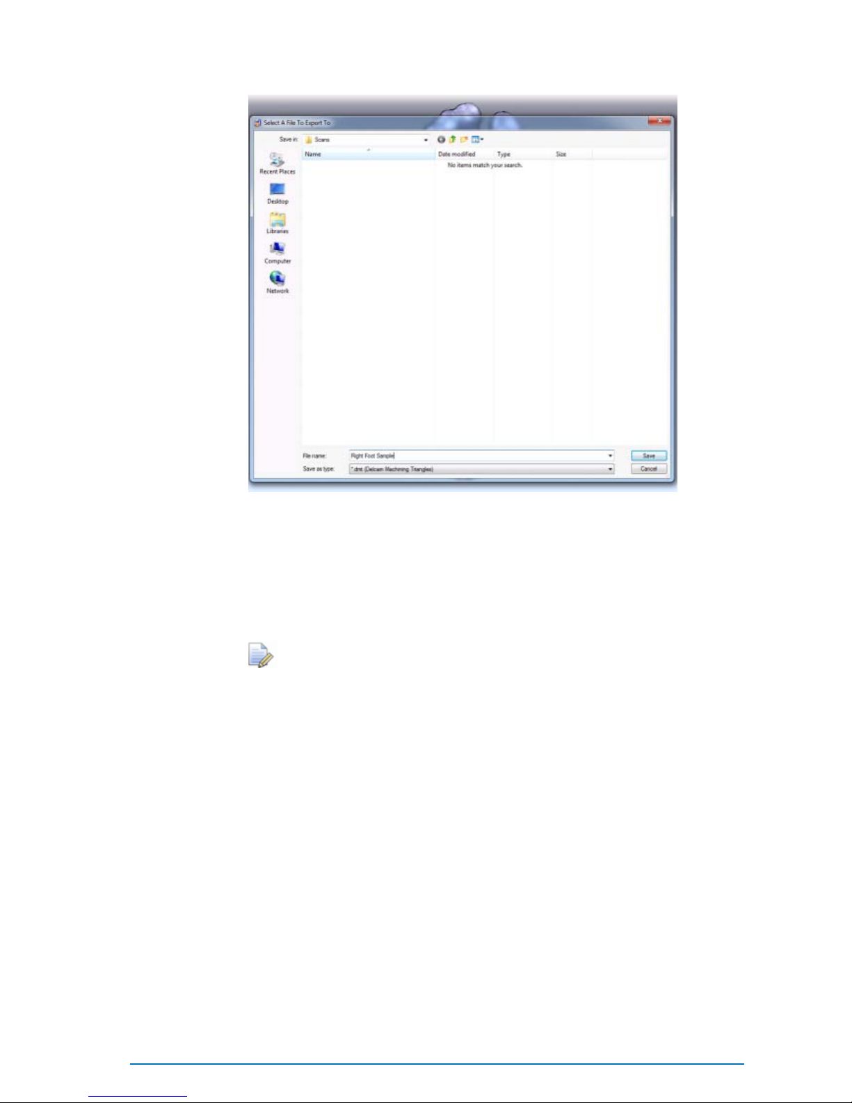
50 • Using the Delcam Orthotic Insoles Software Delcam iQube 2010 Reference Manual
3. Navigate to the required location.
4. Enter the filename.
5. Click Save.
The mesh file is saved as <filename>.dmt in the selec ted location.
The image file is saved as <filename>.bmp in the selec ted location.
The scan files can only be saved as Delcam Machining
Triangles (*.dmt)
6. If required, repe at steps 2 - 5 to save the data for the ot her foot.

Delcam iQube 2010 Reference Manual Scanning Procedures • 51
This section provides detailed information on the preparation, s can
techniques and optimal settings for scanning the positive form of the foot,
a foam box impression or cast.
Scanning a Foot (see page 51)
Scanner Setup (Foot) (see page 52)
Orientation & Location (Foot) (see page 54)
Scan Settings (Foot) (see page 54)
Scanning a Foam Box Impression (see page 55)
Scanner Setup (Foam Box Impression) (see page 56)
Orientation & Location (Foam Box Impression) (see page 58)
Scan Settings (Foam Box Impression) (see page 59)
Scanning a Cast (see page 60)
Scanner Setup (Cast) (see page 61)
Orientation and Location (Cast) (see page 61)
Scan Settings (Cast) (see page 62)
Scanning Procedures

52 • Scanning Procedures Delcam iQube 2010 Reference Manual
Scanning a Foot
The following sections give details on sc anning a foot:
Scanner Setup (Foot) (see page 52)
Orientation & Location (Foot) (see page 54)
Scan Settings (Foot) (see page 54)
For Best Results:
1. Switch the scanner on for at least 5 minutes before use.
2. Ensure the t op face of the scanner is smudge and dust free.
3. Ensure the patie nt’ s f oot is clean and dry .
Scanner Setup (Foot)
Weight On
Extend the support legs (1 6) and place the lid (13) adjacent to the
scanner. This will enable the patient to place one fo ot on the lid a nd one
on the tempered glass screen (2) of the scanner body (1).
Maximum Weight: 200kg. Do not exce e d
maximum weight on the glass.
Do not jump on the glass.

Delcam iQube 2010 Reference Manual Scanning Procedures • 53
Semi-Weight Bearing
1. Extend one e nd of the support legs (16) whilst the other, closed end
is placed onto the floor surface.
2. Take the scanner body (1) and place onto the lid ensuring the
iQube logo is towards the bottom.
Weight Off
1. Extend the support legs (1 6) and place the lid (13) perpendicular to
the scan orientat i on.
2. Lift the scanner body (1) an d place vertically onto the lid (13)
ensuring the iQu be lo go is tow a rd the b otto m .

54 • Scanning Procedures Delcam iQube 2010 Reference Manual
Orient ation and Location (Foot)
1. Ensure that the foot is orientated with the heel at the iQube logo
end of the scanner with its axis parallel to the scanner body side.
2. Locate the foot centrally over the gla ss.
3. If required manipulate the foot into position prior to the scan. A ny
unwanted data can be disca rded at a later point but ensure that you
do not to cover any part of the plantar surface during the scan.
In the case of a Weight Off scan the plantar surface of the foot
must be within 50mm of the s canner surface.
4. Depending on the quality of the data, it may be necessa ry to move
the foot laterally across the glass so that the medial edge is closer
to the edge of the glass aper t ure .

Delcam iQube 2010 Reference Manual Scanning Procedures • 55
Scan Settings (Foot )
Depending upon the colour of the patient’s foot and the amount of detail
required it may be necessary to adjust the Colour and Detail.
Default settings are:
Detail - Medium-High
Colour - 2nd Darkest
The above settings are ideal for a typical Caucasian foot.
If you are experiencing missin g/sparse data try a darker colour
setting.
If you experiencing large amounts of noise try a li ghter colour
setting.
If you need more detail in the data then try a higher detail
setting (th is will increase the data processing time).
To change the scan settings and/or action the scan of a foot see Using th e
Delcam Orthotic Insoles Software. (see page 32)

56 • Scanning Procedures Delcam iQube 2010 Reference Manual
Scanning a Foam Box Impression
This can only be performed with the five camera system(E500).
The following sections give details on sc anning a Foam Box
Impression:
Scanner Setup (Foam Box Impression) (see page 56)
Orientation & Location (Foam Box Impression) (see page 58)
Scan Settings (Foam Box Impression) (see page 59)
For Best Results:
1. Switch the scanner on for at least 5 minutes before use.
2. Ensure the t op face of the scanner is smudge free.
3. Blow any excess dust from the foam box before inverting the foam
box for scanning (reduces d ust deposited onto scanner glass).
4. Initially u se two 45mm lif ters (21) to lift the heel end of the foam
box. The lifters enable the angled lasers and cameras to see more
of the negative imp re ss io n.
5. For deeper foam boxes, increase the heigh t by add ing the
extensions (22) to the current lifters at the heel end. At the toe end
of the impression, add two 4 5mm lifters (21).

Delcam iQube 2010 Reference Manual Scanning Procedures • 57
Scanner Setup (Foam Box Impression)
Place scanner body on a fla t surface (lid is not required).
With 45mm lifters:
It is suggested that for all foam boxes (40 or 55mm depth) two 45mm
lifters (21) are used at the heel end to ra ise the heel end of the foam box.

58 • Scanning Procedures Delcam iQube 2010 Reference Manual
With the 45mm Lifters + 40mm Extensions
Use 21 and 22 as shown below:

Delcam iQube 2010 Reference Manual Scanning Procedures • 59
Orient ation and Location (Foa m Box Impression)
1. Ensure that the impression is orienta ted with the toes at the iQube
logo end of the scanner with its axis parallel to the scanner body
side.
This is the opposite orientation to a foot.
2. Locate the foam box centrally within the glass aperture.

60 • Scanning Procedures Delcam iQube 2010 Reference Manual
Scan Settings (Foam Box Impression)
Depending on the col our of the foam box and the amount of det a il
required it may be necessa ry to adjust the Colour and Detail.
Default settin gs ar e:
Detail - Medium
Colour - 2nd Lightest
The above settings are idea l for red colo ured foam.
If you are experiencing missing/sparse data try a darker colour
setting.
If you experiencing large amounts of noise try a lighter colour
setting
If you need more detail in the data then try a higher detail setting
(this will in crease the data processing time)
To change the scan settings and/or action the scan of a foam box please
see Using the Delcam Orthotic Insoles Software (see page 32).

Delcam iQube 2010 Reference Manual Scanning Procedures • 61
Scanning a Cast
This can only be performed with the five camera system (D500).
The following se ct ions gi ve details on scanning a Cast:
Scanner Setup (Cast) (see page 61)
Orientation and Location (Cast) (see page 61)
Scan Settings (Cast) (see page 62)
For Best Results
1. Switch the scanner on for at l ea st 5 minutes before use.
2. Ensure the top face of the scanner is smudge and dust fre e.
3. Trim the cast down to the required horizon line or just a bove. This
will enable the sca nn er to vie w ins id e the cas t.
4. If required, use a 45mm lifter (21) to raise the heel end of the cas t.
This will allow the lasers and cameras to see more of the inside of
the cast.
Scanner Setup (Cast)
Place scanner body on a fla t surface (lid is not required).

62 • Scanning Procedures Delcam iQube 2010 Reference Manual
Orientation and Locati on (Ca st)
1. Ensure that the cast is orientated with the toes at the iQube logo
end of the scanner with its axis paralle l to the scanner body side.
This is the op posite orientation to a foot.
2. Locate the cast centrally within the glass aperture i n o ne of the
following ways:

Delcam iQube 2010 Reference Manual Scanning Procedures • 63
Scan Settings (Cast)
Depending on the col our of the cast and the amount of de tail require d it
may be necessary to adjust the Colour and Detail.
Default settin gs ar e:
Detail - Medium
Colour - Light
The above settings are idea l for a white cast.
If you are experiencing missing/sparse data try a darker colour
setting.
If you experiencing large amounts of noise try a lighter colour
setting
If you need more detail in the data then try a higher detail
setting(this w i ll inc re ase t he dat a proc e s sing tim e)
To change the scan settings and/or action the scan of a cast see Using the
Delcam Orthotic Insoles Software (see page 32).

64 • Manufacturer Details Delcam iQube 2010 Reference Manual
The Delcam iQube 3D Scanner was manufactured by:
UAB "Elinvision"
Terminal str.3
Biruliskiu Village
Karmelava
Kaunas District
LT-54469
Lithuania
Manufacturer Details

Delcam iQube 2010 Reference Manual Index • 65
A
Adding a Job • 29
C
Cautions • 7
Change the default scan item • 36
Change the timer delay • 35
Change to high definition foot capture
mode • 35
Changing the Default Scan Settings •
34
Changing the sca n set ti ngs ( per
session) • 33
Changing the sensitivity and
resolution • 36
Compliance • 2
Compliance and Safety • 2
Connecting to the Scanner • 18
D
Deleting a Job • 29
E
Electrical Connection • 14
Electrical Specifications • 4
Export Page • 40
F
FCC • 2
H
Handling • 23
Hardware diagram - legend • 12
Hardware Diagrams • 11
Hardware installation and
maintenance • 9
I
Installatio n • 25
Introduction • 1
J
Jobs Page • 28
M
Maintenance • 23
Maintenance and Handling • 23
Manufacturer Details • 53
Mode 1 - Take scan immediately • 38
Mode 2 - Retrieve scanned data • 38
Index

66 • Index Delcam iQube 2010 Reference Manual
N
Network Con nection • 15
O
Orientation and Location (Cast) • 51
Orientation and Location (Foam Box
Impression) • 49
Orientation and Location (Foot) • 45
P
Parts List • 9
Permissibl e Environmental
Conditions • 4
Power-up the Scanner • 16
R
Remove the Cover • 13
S
Safety Precautions • 5
Scan mode • 38
Scan Model • 32
Scan Page • 30
Scan Settings (Cast) • 52
Scan Settings (Foam Box Impression)
• 50
Scan Settings (Foot) • 45
Scanner Setup (Cast) • 51
Scanner Setup (Foam Box
Impression) • 47
Scanner Setup (Foot) • 43
Scanning a Cast • 51
Scanning a Foam Box Impression • 46
Scanning a Foot • 42
Scanning Proce dures • 42
Setting up t he scanner • 13
Software Installation • 25
System Requirements • 25
T
Technical Specifications • 4
Temperature Range • 4
Test • 26
Test the Connection • 22
U
Understand ing Precautio n Terms • 5
Understand ing Warning Terms • 5
Using the Delcam Orthotic Insoles
Software • 28
W
Warnings • 6
WEEE • 3
 Loading...