


Delasco
Electricator
OPERATOR’S MANUAL
OPERATOR’S MANUAL
®
(10/15) REV H

In the event that you need assistance related to this product,
please call Delasco at 800-831-6273 (712-323-3269).
Safe and effective electrosurgery is dependent not only on
equipment design but, also, to a large extent on factors under
the control of the operator. It is important that the instructions
supplied with this equipment be read, understood,
and followed in order to enhance safety and effectiveness.
© 2009 Dermatologic Lab & Supply, Inc.
608 13th Avenue, Council Bluffs, IA 51501-6401 USA
Web: www.delasco.com • Email: questions@delasco.com
Local & International Phone: 1-712-323-3269
Local & International Fax: 1-712-323-1156
Toll-Free Phone: 1-800-831-6273
For all 50 states, Canada and Puerto Rico.
Toll-Free Fax: 1-800-320-9612
For all 50 states, Canada and Puerto Rico.
((03/13) REV G)

Table of Contents
Title Page
I. Introduction, Inspection & Precautions 1-2
II. Device Diagram & Description 3
III. Setup & Operating Instructions 4-5
IV. Common Electricator Techniques 5
V. Periodic Inspections & Maintenance 5
VI. Cleaning, Storage & Sterilization 6
VII. Troubleshooting 7
VIII. Unit Specifications 8
IX. Symbology 9
X. Available Accessories 10
XI. Graph Power vs. Dial Setting 11-12
XII. Load Regulation Curves 13-14

I. Introduction, Inspection &
Precautions
Indications for Use
The Delasco Electricator is a non-sterile, reusable, electrosurgical generator. The Electricator is
intended to be utilized for destroying small lesions and to coagulate small bleeders by applying high frequency current via an electrode.
Inspection
The Delasco Electricator includes:
• One (1) Electrosurgical Unit
• One (1) Power Cord
• One (1) Handpiece
• One (1) Wall Mount Kit
• One (1) Starter Pack of Electrolite
• One (1) Starter Pack of Delasco Electrosurgical Handpiece Sheaths
• Operator’s Manual
®
Disposable Electrodes
Upon receipt of your Delasco Electricator, carefully unpack the contents, and verify that all
items ordered are present and undamaged. If damage has occurred during shipment, or an
item is missing, contact Delasco within ten days of purchase.
1

Precautions
CAUTION: Federal (U.S.A.) law restricts the sale of this device to or on the order of a
physician or health care professional.
CAUTION: This device is supplied non-sterile.
WARNING: The risk of igniting flammable gases or other materials is inherent in the
practice of electrosurgery and cannot be eliminated by device design.
Precautions must be taken to avoid contact of flammable materials and
substances with electrosurgical electrodes, whether they are in the form
of an anesthetic or skin preparation agent, are produced by natural
processes within body cavities, or originate in surgical drapes, tracheal
tubes, or other materials.
WARNING: The Electricator delivers high frequency current to the patient. The cur-
rent will normally travel through the patient, to ground, and return to
the Electricator. If an alternative pathway develops, a slight shock may
be felt by the patient or physician. To reduce the potential of an alternative pathway:
• Do not allow the patient to touch grounded metal objects
during the procedur
• If touching the patient during a procedure, maintain firm con-
tact and do not remove your hand until activation is complete.
• If possible, wear exam gloves during procedures.
• If using the optional metal grounding plate, place the grounding plate on a fleshy area and insure that complete coverage of
the plate is maintained during the procedure.
WARNING: Electrosurgery should not be used to perform circumcisions.
CAUTION: Use of electrosurgical devices can cause severe electromagnetic inter-
ference in other devices, particularly cardiac pacemakers; precautions
should be taken to ensure that the patient’s well-being is maintained in
the event of such interference.
CAUTION: Studies have shown that smoke generated during electrosurgical proce-
dures may be harmful to surgical personnel. These studies recommend
using a surgical mask and adequate ventilation of the smoke using a
smoke evacuator or other means.
2

II. Device Diagram & Description
Memory Functions:
Store favorite output settings.
LED Display: Illuminates
when the unit is turned “On”
and brightens during output
activation.
Dial Setting Knob: Allows
for the adjustment of the unit
output. Settings are from 0-25
in the “Low” setting and 0-45 in
the “High” and “Bipolar” setting.
Cautery Electrode: The tip of the
electrode is used to deliver electrosurgical current to the patient.
Electrode Collar: Secures
the electrode in the handpiece.
Handpiece Activation Button:
Activates the Electricator®.
Up / Down Controls:
Adjusts output levels.
Cautery Handpiece: Used to
deliver current to the electrode.
MODE Selection: Allows
for the selection of “Low”,
“High” or “Bipolar” output.
Handpiece / Forcep
Cable Receptacle:
The handpiece cable or
the optional bipolar
forcep cable is connected
to this receptacle.
Patient Plate Connection:
If the patient grounding plate
is used, the connecting cable
is inserted into this receptacle.
Handpiece Holder:
During non-use periods,
the handpiece may be
stored in this holder.
On / Off Switch: Turns
Delasco Electricator power
“On - I” and “Off - O”.
Power Cord Connection:
The power cord is
connected at this point.
Footswitch Connection: The optional
footswitch is connected at this point.
3

III. Setup & Operating Instructions
CAUTION: If you are unfamiliar with electrosurgery, it would be wise to practice on a large
piece of lean flank steak. Hold the steak firmly in one hand (or place it on a table) and practice
activating the unit in the various modes and dial settings.
CAUTION: When unsure of the output level to use during a procedure, begin at a low setting
and increase the output gradually to prevent unnecessary damage to the patient.
1. Mount the unit on a wall or optional mobile
stand using the Wall Mount Kit. To reduce the
potential of fluids entering the unit, do not use or
store the unit in a horizontal position.
2. Insert the female end of the power cord into
the unit and plug the male end into a grounded
electrical outlet.
3. Align the Handpiece Connector with the
Handpiece Receptacle on the bottom of the unit.
Insert the Connector until a secure fit is obtained.
4. Insert an Electrolite® electrode into the handpiece and secure by rotating the collar. To
prevent cross contamination, an electrosurgical
handpiece sheath may be applied to the handpiece prior to insertion of the electrode.*
5. If an optional footswitch is used, make sure
power to the unit is off and insert the male end of
the footswitch completely into the receptacle at
the bottom of the unit. Failure to insert
the male end of the footswitch completely may result in an error code being displayed or
possible damage to the unit.
6. If an optional patient plate is used, insert the
female end of the cord into the insertion hole
along the lower panel of the unit (for plate placement instructions, follow the instructions supplied with the patient plate).
7. Turn the power to the unit on by pressing the
on/off switch to the on position.
8. When the power is first turned on, a self diagnostic test of the unit is performed. If a fault is
discovered, an error code will appear in the display window. An explanation of the error codes
is found in section VI.
9. Select Low, High, or Bipolar modes using the
Mode button. If Bipolar is selected, a bipolar forcep and cord must be attached to the handpiece/
forcep cable receptacle.
10. Adjust the power output to the desired setting using the Dial Setting Knob or the Up/Down
Handpiece controls.
11. To activate the unit, press the round activation button on the handpiece (or optional
footswitch). Upon activation, an audible will be
heard & the LED Display brightens.
12. When switched on, the previously used settings in all three modes are maintained in memory. In addition, three extra memory settings are
available. To enter the extra memory settings, set
the Dial Setting Knob and Mode selection to the
desired output and press and hold the desired
memory button until an audible is heard. The
remaining two memory buttons may be used for
two additional favorite settings.
13. When the procedure is complete, turn the
unit off by switching the On/Off switch to the off
position.
14. For Bipolar procedures, the Forceps are connected to the Electricator Forcep Cord, which is
then attached to the unit using the same connection receptacle as the Handpiece. The forceps
are then activated with a footswitch. Please note
that due to the special high voltage connector,
only the Delasco Electricator Forcep Cord will fit
the Delasco Electricator unit.
* To insert an electrode using a sheath: In order to prevent binding of the sheath, twist the collar to the near-closed position,
apply the sheath, then insert the electrode and twist the collar to lock.
4

Audible Volume Adjustment
To adjust the volume of the Electricator audible, turn the unit power on while simultaneously
holding down the Memory 1 button. Adjust the audible to the desired volume using the Dial
Setting Knob. Turn the unit off and then back on to return the unit to normal operation.
IV. Common Electricator Techniques
Desiccation: A monopolar (Low or High) technique whereby the electrode is placed in contact
with or inserted into the tissue and activated, causing tissue destruction.
Fulguration: A monopolar technique (Low or High) whereby the electrode is held slightly
above the tissue and the current arcs to the tissue. Fulguration results in less tissue damage
as it is more superficial. In reality, many procedures combine both desiccation and fulguration.
Coagulation: There are three ways to coagulate small bleeders using the Electricator:
1. Touch the monopolar electrode to the bleeder and activate (Low or High).
2. Utilize the optional patient plate (follow directions supplied with plate) and touch the
electrode (Low or High) to the bleeder and activate (the addition of the patient plate
produces more effective coagulation).
3. Bipolar forceps may also be used (requires use of footswitch) to coagulate small bleeders (Bipolar Mode). Forceps produce less tissue damage than other methods, as the
current flows only from one tip of the forceps to the other.
V. Periodic Inspections &
Maintenance
1. Delasco reccomends that you periodically inspect this unit both visually and for output
performance. Output performance should be checked annually by a qualified biomedical technician to ensure optimal performance.
2. Device should be visually inspected monthly for signs of damage or wear in the following areas:
- Any damage to the power cord or power cord receptacle
- Damage to the housing or front panel touch pad
- Damage to the handpiece, handpiece cord or handpiece receptacle
- Device should be clean and free of lint, dirt or debris
5

VI. Cleaning, Storage & Sterilization
Unit Cleaning
CAUTION: To reduce the risk of an electric shock, do not remove the rear cover of the instrument.
Refer all servicing to qualified personnel.
CAUTION: Disconnect the unit power cord from the power receptacle prior to performing cleaning
operations.
Periodic external cleaning of the Delasco Electricator is required. Clean all external surfaces
with a mild soap and water solution using a moist, soft, lint-free cloth. Dry all surfaces with a
clean, lint-free cloth.
CAUTION: Care must be exercised to ensure that the electrical connections and control knob do
not come in contact with water.
Unit Storage
Store the Delasco Electricator in a cool, dry place.
Sterilization of Handpiece
The Handpiece may be autoclaved according to the instructions below.
• Separate the Electrode from the Handpiece prior to autoclaving and use aseptic proce-
dures when handling and sterilizing the Handpiece.
• Wipe and remove all debris present on the Handpiece.
• Place the Handpiece in an autoclavable pouch or wrapped cloth.
• Steam sterilize for a period of 20 minutes at 250°F(121°C) (Do not flash autoclave or
exceed 250°F). Consult manufacturers’ recommendations, or the AAMI recommended
practice for Steam Sterilization Using The Wrapped Method.
• Allow the Handpiece to cool for 30 minutes prior to use.
• Inspect the Handpiece after sterilization for damage. If the Handpiece has deteriorat-
ed or cracked, or severe discoloration or damage has occurred, discard and replace if
autoclaved more than 40 times. If less than 40, contact Delasco for warranty information.
CAUTION: Do not use liquid sterilizing solutions with the Delasco Electricator or accessories, as the
potential for material damage exists.
NOTE: The disposable Electrolite electrosurgical electrode and disposable handpiece sheath
are designed to be discarded after use to prevent cross contamination and are not to be
reused.
6

VII. Troubleshooting
Error Codes
During start up, the Electricator will perform self-diagnostics. If an error is discovered, the unit
will become inoperable and an error code will appear in the display window. Contact Delasco
immediately if an error code is displayed. The following is a list of
possible error codes:
MAIN PROCESSOR SECONDARY PROCESSOR
E1 EPROM failure N/A
E2 EEPROM failure N/A
E3 CPU COM failure CPU COM failure
E4 Critical RAM failure Critical RAM failure
E5 ADC Voltage failure N/A
E6 V_SNS Voltage failure N/A
E7 Stuck FS or HC N/A
E8 Stuck FP Key N/A
E9 Cal EEPROM failure N/A
Warranty & Repair
Delasco has exercised care in the manufacturing of the Electricator. The warranty period for
the unit is two years from the date of purchase and covers parts and labor. The warranty for
the Handpiece is one year from date of purchase or 40 autoclave cycles, whichever occurs first.
The warranty is limited to the repair or replacement of the unit at the discretion of Delasco.
Warranty may be voided if the unit or handle has been subject to abuse.
Items for repair (warranty and non-warranty) should be sent with all original packaging and
instructions included. Please use proper packaging to prevent damage during shipment.
We recommend that you insure the return with your chosen carrier for loss or damage. Call
Delasco for a Return Goods Authorization code and include this code on the outer shipping
container. Include a copy of the original invoice with the return and state the reason for the
return. Freight charges for warranty and non-warranty repairs are the responsibility of the
customer.
Please contact Delasco at 800-831-6273 or 712-323-3269 to advise that you are returning a
Delasco product and to obtain an RGA number.
7

VIII. Unit Specifications
FEATURE DESCRIPTION
Primary Power Requirements 100-240V, 50/60 Hz
Maximum Supply Current 1.7 Amps
Fundamental Output Frequency 350-490 KHz +/- 50 KHz
Output Wave Shape Clipped, Damped, Sinusoidal
Maximum Output Power / Rated Load Low - 25 watts / 500 ohms
High - 45 watts / 1000 ohms
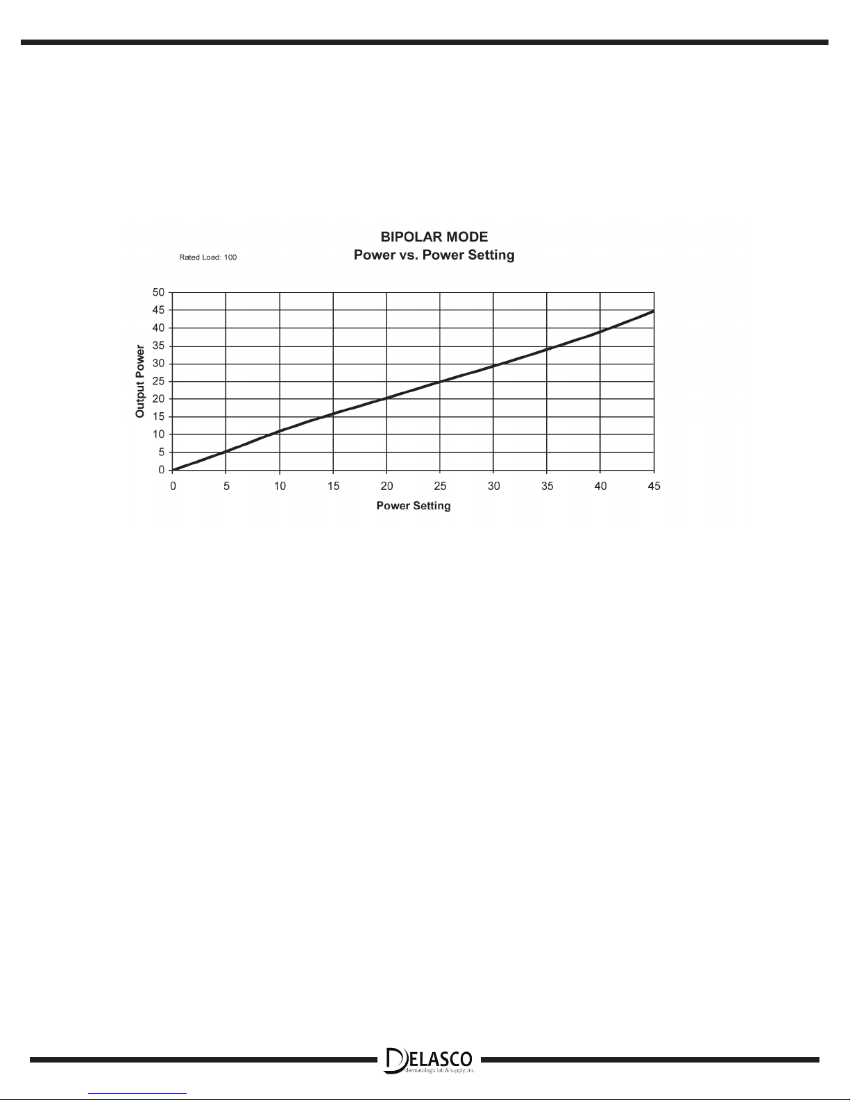
Bipolar - 45 watts / 100 ohms
Maximum Voltage Open Circuit Low - 3800 Vpp
High - 8500 Vpp
Bipolar - 1600 Vpp
Duty Cycle 30 sec ON / 30 sec OFF
Display Reading Low 0.1-10 range: 0.1 watt increments
10-25 range: 1 watt increments
Display Reading High & Bipolar 0-45 range, 1 watt increments
Audio Tone Frequency: 1 KHz
Volume Control: 8 settings
Sound Level: Min 45 db
Operating Temperature Range +10° to +40° C
Relative Humidity 10% to 95% non-condensing
Storage Restrictions -40° to +70° C, 95% humidity
Protection BF Defibrillator, Class 1
Dimensions 8.75” H x 6.5” W x 3.0” D
Weight 6 lbs.
High Frequency Leakage Currents Monopolar Patient Leakage
(as per IEC 60601-2-2, Section
19.3.101.a.1): 150mAmps Max
Bipolar Patient Leakage
(as per IEC 60601-2-2, Section
19.3.101.a.3): 45mAmps Max
Low Frequency Leakage Currents Enclosure (as per IEC60601-1,
Section 19.3, Type BF): 50 microAmps Max
Monopolar Patient Leakage
(as per IEC 60601-1, Section
19.3, Type BF): 50 microAmps Max
Bipolar Patient Leakage
(as per IEC 60601-1, Section
19.3, Type CF): 7.5 microAmps Max
8

IX. Symbology
1 2 3 4 5 6 7 8 9 10
1. Handpiece Connection
2. Forcep Connection
3. Caution: Site is source of high voltage
4. Patient Plate Connection
5. Neutral Electrode Referenced to Earth
6. BF Equipment Classification
7. Footswitch Connection
8. Read Operator’s Manual prior to using the device
9. Power On/Off
10. RF Power Adjustment
9

X. Available Accessories
ACCESSORY CATALOG NUMBER
Autoclavable Power-Switching Handpiece (replacement) 26300
Electrolite® electrode, box of 100 (additional) 26200
Electrolite® electrode, box of 50, sterile (additional) 26200S
Protective Sheaths, non-sterile, box of 100 (additional) 26100
Footswitch (optional) 26500
Wall Mount Kit (replacement) 26600
Bipolar Forceps (optional, require cord)
McPherson, 3 ½” straight, 0.5mm tip 26401
Adson, 4 ¾” straight, 1.0mm tip 26402
Semkin, 5 ½” straight, 0.5mm tip 26403
Cushing, 6 ½” straight, 1.0mm tip 26404
Cushing, 7” straight, 1.0mm tip 26405
Cushing, 7” straight, 2.0mm tip 26406
Gerald, 7” straight, 1.0mmtip 26407
Gerald, 7 ½” bayonet, 1.0mm tip 26408
Bipolar Forcep Cord, Electricator Only 26409
(required for any bipolar forcep use with the Electricator)
Reusable Patient Plate and Cord (optional) 26900
Mobile Stand, Universal 26800
10
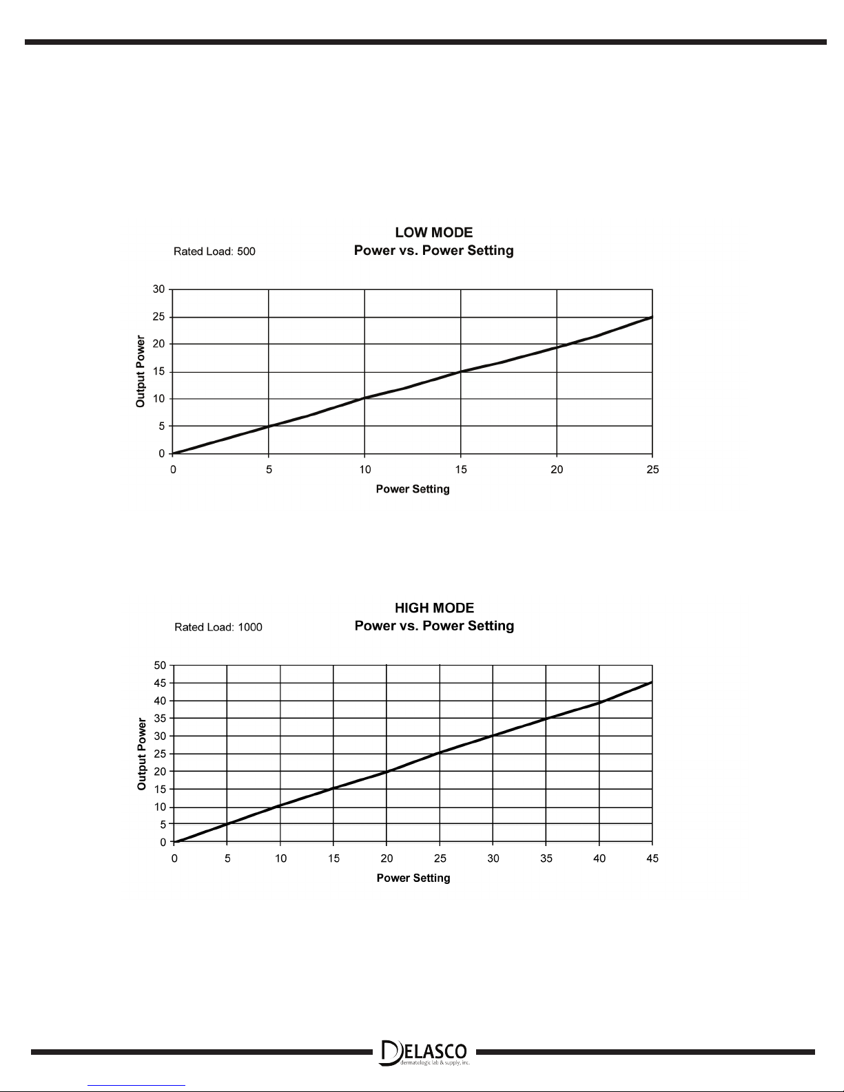
XI. Power vs. Dial Setting
11
12

XII. Load Regulation Curves
13

14

Page Intentionally Left Blank
15
 Loading...