


DEKOR® DECK LIGHTINGInstallation Instructions
DEKOR® DECK LIGHTING Installation Instructions
How to install DEKOR® Deck Lighting / CONTINUED
Installing Stair/Recessed Lights
NOTE: Recessed lights should be installed after stairs and
risers have been installed.
1. Mark location for light,
typically 4” (10.2cm),
1
above tread. Be sure to
check local codes for
lighting requirements.
4”
NOTE: Avoid locations over
(10.2cm)
stringers when possible
because it will be more
dicult to drill holes.
2
3
2. Drill a .9" (23mm) diameter hole at least 1" (2.5 cm)
deep into riser. If riser material is thicker than 1" (2.5
cm), use a 3/8" (8.25mm) drill bit to create a hole for
wires that goes all the way through riser.
3. Thread wires through hole.
4. Press light housing into hole,
4
then insert light and lens.
Make connections behind
stairs. Male lead wire from
recessed light into female
connection on splitter. Also
attach male-to-male
connection wires in between
each splitter. Continue until
all wiring from lights are
attached to splitters and connector wires are attached
in between splitters. (See Making Connections section
for details.)
NOTE: DO NOT install Riser Light or Deck Rail Light into top
or bottom rails or balusters.
Installing Recessed DEK-DOTS™ Deck Lights
NOTE: Install recessed DEK-DOTS™ deck lights after installing decking.
1. Mark location for DEK-DOTS™
NOTE: Avoid locations over
joists when possible
because it will be more
dicult to drill holes.
2. Drill a .9" (23mm)
diameter hole 3/4" (1.9 cm)
deep into deck board.
Make sure hole does not
go all the way through
deckboard or light will fall
through. Drill a 3/8"
(8.25mm) diameter hole
in base of the rst hole
through deck board
making sure drill bit is
perpendicular to board.
3. Thread wires through hole. DO NOT pull DEK-DOT™ into
4. Press DEK-DOT™ into hole until ush with surface.
Make connections under deck. Male lead wire from riser
on deck boards.
1
2
3/4” (1.9cm)
43
hole by pulling on wires. This may damage wires or
DEK-DOT™ .
light into female connection on splitter. Also attach
male-to-male connection wires in between each splitter.
Continue until all wiring from lights are attached to
splitters and connector wires are attached in between
splitters. (See Making Connections section for details.)
PARTS
Illuminated Post Caps
A
(Sizes Vary)
Post Lamps
B
Teardrop Holly
C
» 5’, 10’, 20’, 40’, and 60’ male to male connection/extension
wires sold separately.
LIGHTING AND WIRING OVERVIEW
TOOLS NEEDED
3/8”
(8.25mm)
.9”
(23 mm)
NOTE: All wiring and splitters are mounted to inside of framing, picture is just representation of where
to place these in general.
NOTE: Avoid railing brackets and locations for deck rail lights when running wires up posts.
NOTE: It is recommended to install wiring and splitters before decking and railing have been installed.
DO NOT run wires between joists and deck boards.
HELPFUL TIPS
» Leave wire slack to make fixture terminations.
» Recessed lights work best when spaced 4’ (1.22m) to 6’ (1.83m)
on center around perimeter of deck.
» Post lights should be at level changes on a deck — at the top or
the bottom of the stairs, or usedin conjunction with post cap
lights.
» Consider local codes when using Recessed lights. If codes do
not available determine number of lights and placement, in
darkness, prior to drilling.
» Carefully drill holes perpendicular to surface to avoid produc-
ing an enlarged hole. Light ture will have a loose t if hole is
enlarged. Use a simi-permanent exible outdoor adhesive
(silicone caulk) to anchor light in place if this happens.
» DEKDOT™ light holes should be drilled to a depth of 3/4" (1.9
cm) Recessed and post lights holes can be through holes.
Silicone caulk will be required to anchor light in place in
over-drilled recessed light holes.
Recessed Lights
Stair Light
Down Light
A
DEKDOT™ Lights
D
E
D
E
Splitter
B
C
» It is best to use splitters at each post that has lights and
depending on spacing in between each DEKDOT™ and
recessed light.
» Unused female connections need to be capped. Use
provided caps or a weather resistant silicone to prevent
corrosion or water damage.
» There is no specied plug for lights versus lead wires on the
splitter becuse the splitter is cross linked.
» Each light has a lead attached with an approx. 5' to 6' (1.5 m
to 1.8 m) length and have male terminals that plug into
splitter.
» It is recommended to use a separate dimmer control for
each light type for maximum control.
» To ensure all components are in working condition it is
recommended to have power source attached when
installing lights.
14
NOTE: Construction methods are constantly changing. For the most up-to-date installation instructions visit: www.DEKORLIGHTING.com
Have Questions? Call 1–800-258-0344
©2014 DEKOR™, Denver, CO
NOTE: Construction methods are constantly changing. For the most up-to-date installation instructions visit: www.DEKORLIGHTING.com
Have Questions? Call 1–800-258-0344
DEKOR® DECK LIGHTINGInstallation Instructions
DEKOR® DECK LIGHTING Installation Instructions
How to install DEKOR® Deck Lighting / CONTINUED
General Information
» ALWAYS check local codes before beginning your project.
» USE DEKOR® TRANSFORMERS ONLY. Using any other type
of transformer voids the warranty.
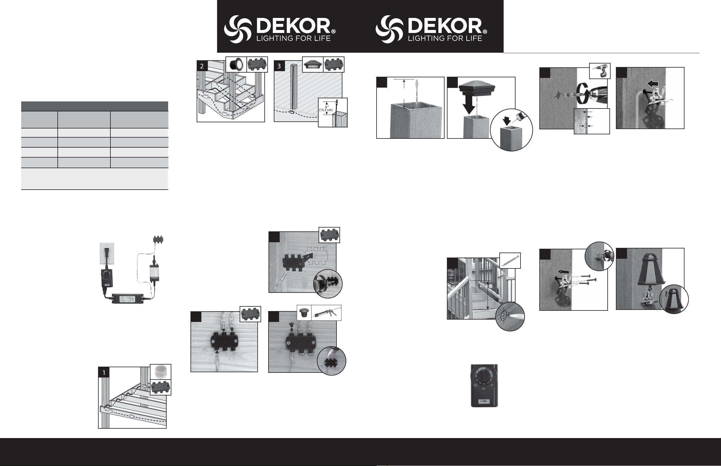
TRANSFORMER CAPACITY BY TYPE
Type of Light
DEK-DOT™ 52 31
Recessed
Post Cap*
Post Light
The list above is for maximum number of each individual types of lights.
If mixing and matching lighting, contact DEKOR to determine if more than one
transformer is needed. *Post Light quantity is based on all 4 sides with lights.
Reference the transformer calculator at dekorlighting.com for other variations.
EZ Max Transformer
Planning
NOTE: Prior to installing, plan locations of lights, power supply,
timer, and dimmer. These need to be accessible for
service. It is required to install a GFI to help prevent
damage to lights caused by electrical surges.
1. Dimmer remote works in
a 30' (9 m) radius of the unit.
2. Install dimmer in a dry
location.
3. You must nstall timer
vertically with receptacle
facing down. Timer must be
at least 1' (.305 m) from
ground level when installed
as per federal safety code
height regulations. To use the dusk/dawn feature the timer
must be in view of the sun.
Installing Wiring
NOTE: It is best to install wiring and splitters before railing
and decking have been installed.
» Connect to each required splitter using Male-to-Male
connection wire (lengths vary).
1. You must be run wiring
under decking structure
and behind stringers.
DO NOT run wires
between joists and deck
boards. Use cable staples
at least 1/4" (0.6 cm) wide
to staple to frame .
DO NOT crush wire
insulation with staple.
5A Transformer
52
15
52
GFCI Outlet
2.5A Transformer
EZ Transformer
31
9
31
To Splitter
Timer
Transformer
Dimmer
(Optional)
2. Wiring can be run under deck and behind risers. Use cable
staples at least 1/4" (0.6 cm) wide to staple wire to frame.
DO NOT crush wire insulation with staple.
3. Remove 5' (1.52 m) lead wire that is connected to post cap.
Attach wire to post with male connection at top of post
(female connection at bottom of post to connect with
male-to-male extension to connect into splitter). Avoid
running wire on side of post where railing brackets or deck
rail lights will be installed. Leave approximately 6" (15.2 cm)
of lead at top to make connections. Staple to frame and
posts with cable staples at least 1/4" (0.6 cm) wide.
DO NOT crush wire insulation with staple.
Making Connections
1
1. Using hardware provided
install splitters to inside
of framing . Install at
every post base where
lighting is present and
depending on spacing in
between each riser and
recessed light.
2
Light
connection
2. Attach male lead from lights to female connections on splitter.
Attach male-to- male connection wires in between each splitter.
Continue until all wiring from lights are attached to splitters and
connector wires are attached in between splitters.
3. Cap o all unused female connections on splitters using caps
provided or weather-resistant silicone.
Connection
wire
Connection wire
3
How to install DEKOR® Deck Lighting / CONTINUED
Installing Post Cap Lights
1
6”
(15.2 cm)
NOTE: Install post cap lights after the railing system,
post sleeve skirt, and post sleeve have been installed.
1. Connect male lead from wiring to female connector from
cap. Attach male-to-male connection wires in between each
splitter. Continue until all wiring from lights are attached to
splitters as well as connector wires are attached in between
splitters. (See Making Connections section for details.)
2. Attach cap to top of post with silicone caulk after verifying
wiring is correct by turning lights on.
Installing Post Lights
NOTE: Instructions shown below are for new deck installation
and are shown BEFORE railing system has been installed.
1. Place post sleeve over
pressure-treated post and
mark desired height,
centered on post sleeve for
deck rail light location.
NOTE: If deck boards are not installed yet place an appropriate
deck width spacer board to ensure post sleeve is at
correct height.
Timer Operation Instructions
1. Select the mode of operation:
» Dusk to Dawn
» 1 - 8 hours
» Always “On”
» “O ”
Program repeats daily. When power is owing to lights,
green light above POWER is on.
2
2
1
3
1
2
Post
Post
Sleeve
3
2. Drill a 3/8" (8.25mm) hole through post sleeve. Be sure to
stop drill before cutting into post.
3. Remove the post sleeve from the post and sh wire from
deck rail light through hole and down to female connector on splitter. Attach male-to-male connection wires in
between each splitter. Continue until all wiring from lights
are attached to splitters as well as connector wires are
attached in between splitters. (See Making Connections
section for details.)
IMPORTANT NOTE: Before attaching deck rail light to the
post/post sleeve make sure decking has been installed
along with skirt over the post sleeve.
4
5
4. Replace post sleeve over pressure-treated post and align
holes for screws vertically and attach xture base to post
with provided screws.
5. Line up and slip on Post Light housing.
NOTE: If railing has already been installed, lead wires will
need to be shed through the post sleeve to reach the
desired location for the deck rail light. In some cases if
the provided lead wire does not t (due to connector
size), the wire connectors can be cut o and wire nuts
can be used. Test lights with the power on and if lights
do not function that are wired with this method,
switch the connector wires.
32
NOTE: Construction methods are constantly changing. For the most up-to-date installation instructions visit: www.DEKORLIGHTING.com
Have Questions? Call 1–800-258-0344
NOTE: Construction methods are constantly changing. For the most up-to-date installation instructions visit: www.DEKORLIGHTING.com
Have Questions? Call 1–800-258-0344
 Loading...