

Page 1
Dekolink WIRELESS Ltd.
16 Bazel St. Qiryat-Arieh Petah-Tikva, Israel, 49510
Tel- 972-3-9180-180 Fax-972-3- 190-9180
e-mail: marketing@dekolink.com
web www.dekolink.com
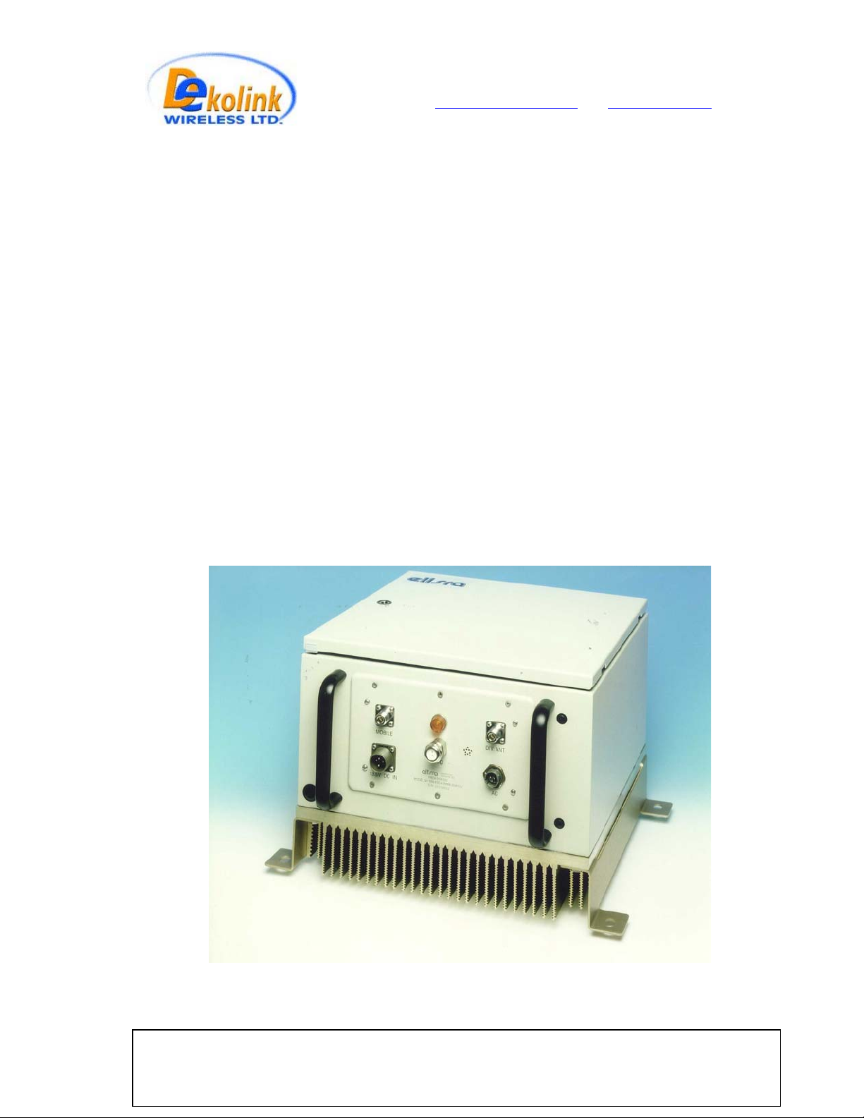
INSTALLATION AND
OPERATION INSTRUCTIONS
FOR
FiberLink
BI-DIRECTIONAL AMPLIFIER
WITH DIVERSITY
MW-FBDA-SMR8-50W-DIV
Dekolink Wireless Proprietary and Confidential Information. Copying, Distribution, and Disclosur
rev3 08/03 Page 1 of 17
prohibited without Express Authorization from Dekolink Wireless Company.
This document is protected by all applicable copyright laws.
e are
Page 2

Dekolink WIRELESS Ltd.
16 Bazel St. Qiryat-Arieh Petah-Tikva, Israel, 49510
Tel- 972-3-9180-180 Fax-972-3- 190-9180
e-mail: marketing@dekolink.com
web www.dekolink.com
TABLE OF CONTENTS
Para No.
1. OVERVIEW 3
2. COMPONENT DESCRIPTION 5
2.1 DUPLEXER 5
2.2 UPLINK AMPLIFIER 5
2.3 50 WATT DOWNLINK POWER AMPLIFIER 5
2.4 FIBEROPTIC TO RF TRANSCEIVER 5
2.5 RFIBER TRANSMITTER 7
2.6 MONITOR UNIT 7
2.7 POWER DISTRIBUTION UNIT 10
2.8 POWER SUPPLY 10
3 SPECIFICATIONS 11
3.1 RF SECTION SPECIFICATIONS 11
3.2 FBDA ALARM SPECIFICATIONS 12
3.3 MECHANICAL SPECIFICATIONS 12
3.4 ENVIRONMENTAL CONDITIONS 12
Paragraph
Page No.
4 RF EXPOSURE WARNING 13
DEKOLINK WIRELESS LIMITED WARRANTY 17
LIST OF FIGURES
Fig No.
1 FBDA RF BLOCK DIAGRAM
2 RFIBER FRONT PANEL
3 RFIBER REAR PANEL
4 MONITOR OUTLINE
5 FIBERLINK ALARM BLOCK DIAGRAM 9
6 FBDA SYSTEM BLOCK DIAGRAM 14
7 MECHANICAL LAYOUT 15
8 MECHANICAL OUTLINE 16
rev3 08/03 Page 2 of 17
Fig. Name
Page No.
4
6
6
8
Page 3

Dekolink WIRELESS Ltd.
16 Bazel St. Qiryat-Arieh Petah-Tikva, Israel, 49510
Tel- 972-3-9180-180 Fax-972-3- 190-9180
e-mail: marketing@dekolink.com
web www.dekolink.com
1. OVERVIEW:
The FBDA is an interface unit between optical signals carrying RF information, and RF
antennas covering a defined user area. The system consists of uplink path and
downlink path and an additional uplink path for diversity.
The uplink path receives RF signals from the Mobile antenna amplifies them and the
Rfiber+ converts them to optical signals. These optical signals are sent to the BTS.
The downlink path receives optical signals from the BTS to the Rfiber+, converts them
to RF signals and amplifies these signals using a high power amplifier. The Mobile
antenna transmits these RF signals.
A duplexing filter separates the frequencies of uplink path from the downlink path
enabling the use of the same antenna for receiving and transmitting. The FBDA
provides about 46 dB RF GAIN in both directions.
Both optical signals for Uplink and Downlink are carried on a single fiber using WDM.
The Rfiber+ RF output power is aligned to 0 dBm for proper operation. Downlink gain
can be adjusted using a step attenuator for required output power.
Uplink gain can be adjusted by 16 dB continuous trim pot on the uplink pre amplifier.
The downlink path uses a 50 Watt power amplifier while the uplink uses an AGC pre-
amplifier to drive the uplink F/O transmitter. The AGC is set to 0 dBm, which is the
max power permitted by the F/O transmitter.
For diversity reasons there is an additional Uplink path consisting of Cavity band pass
filter, AGC pre-amplifier, and Fiber optic transmitter. The optical signal of this path is
transferred via an additional fiber to the base station.
rev3 08/03 Page 3 of 17
Page 4
Dekolink WIRELESS Ltd.
16 Bazel St. Qiryat-Arieh Petah-Tikva, Israel, 49510
Tel- 972-3-9180-180 Fax-972-3- 190-9180
e-mail: marketing@dekolink.com
web www.dekolink.com
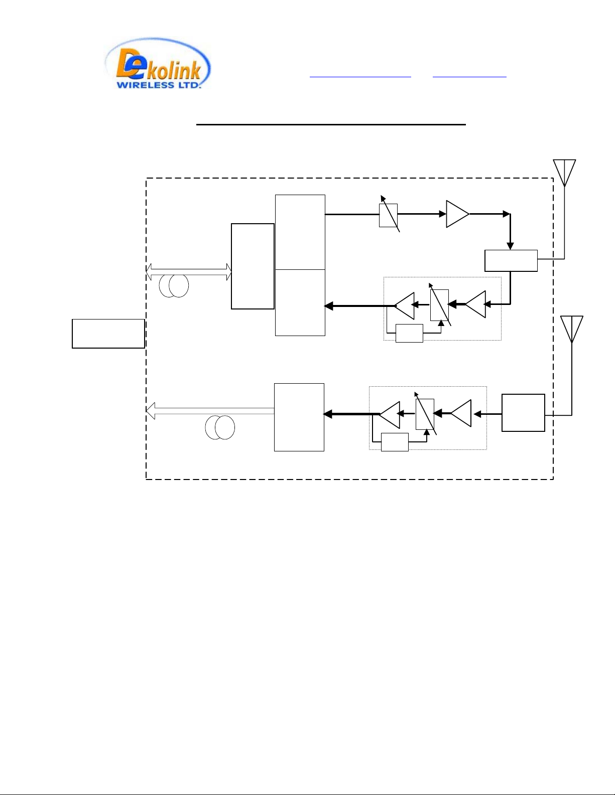
TO BTS
Fig. 1 : FBDA RF BLOCK DIAGRAM
Optical
Fiber
Downlink / Uplink
Optical
Fiber
Uplink
(diversity)
WDM
Fiberoptic
Receiver
Fiberoptic
Transmitter
Fiberoptic
Transmitter
UP LINK
AMP
UP LINK
AMP
Step
Attenuator
AGC
AGC
Down link Power
Amplifier
TX
Duplexer
RX
Variable
Attenuator
Rx1
Filter
Variable
Attenuator
rev3 08/03 Page 4 of 17
Page 5

Dekolink WIRELESS Ltd.
16 Bazel St. Qiryat-Arieh Petah-Tikva, Israel, 49510
Tel- 972-3-9180-180 Fax-972-3- 190-9180
e-mail: marketing@dekolink.com
web www.dekolink.com
2. COMPONENTS DESCRIPTION:
2.1 DUPLEXER(x2)
The duplexer serves to frequency separate uplink signals from downlink signals. The
duplexer has sharp out of band attenuation for better isolation between the receiving
and transmitting paths and for better rejection of interfering signal in the air. In the
Diversity path only the Rx part of the duplexer is used.
2.2 UPLINK PRE-AMPLIFIER(both Rx pathes)
The uplink pre-amplifier is a low noise, 45dB gain unit. The amplifier contains AGC
control circuitry. When a high power signal is received the automatic level control
detects it and reduces the gain so that the output power of the amplifier is constant.
The AGC function limits the signal at the Fiberoptic transmitter input when high power
signals are received while keeping high gain when low power signals are received.
The LED on the amplifier illuminates when the power output of the amplifier exceeds
the AGC power set limit (when the AGC is either ON or OFF).
The Switch on the RF amplifier enables the AGC function. If the AGC is disabled then
the amplifier gives maximum gain for any input.
The AGC level is factory set to 0 dBm and AGC is set to ON, to prevent high power
damage at the Rfiber+ input.
2.3 50 WATT DOWNLINK POWER AMPLIFIER
This is the downlink power amplifier. It can drive 40 dBm composite power to the
mobile antenna. A thermostat attached to this amplifier turns on TEMP alarm when the
temperature exceeds 80° C.
2.4 Fiberoptic to RF transceiver
The RFiber+TM product is a transceiver that includes a transmitter and receiver unit.
The transmitter converts the RF signals into light wave signals, which are then sent
over fiberoptic cables. The receiver converts light wave signals back to RF
The model in use is a wide band product in the 0.08-2 GHz frequency range and it
includes a WDM module to enable use of one fiber for Tx and Rx signals.
rev3 08/03 Page 5 of 17
Page 6
Dekolink WIRELESS Ltd.
16 Bazel St. Qiryat-Arieh Petah-Tikva, Israel, 49510
Tel- 972-3-9180-180 Fax-972-3- 190-9180
e-mail: marketing@dekolink.com
web www.dekolink.com
The RFiber+TM main features are:
1. Protocol transparency; i.e. any standard can be faithfully transmitted.
2. An optional serial port (RS232) is installed into each unit. This port allows
data communication over the same fiberoptic cable.
3. Max. input RF power for normal operation – 0dBm.
4. Manual Gain Control is standard in receiver to compensate for optical loss
across the fiber.
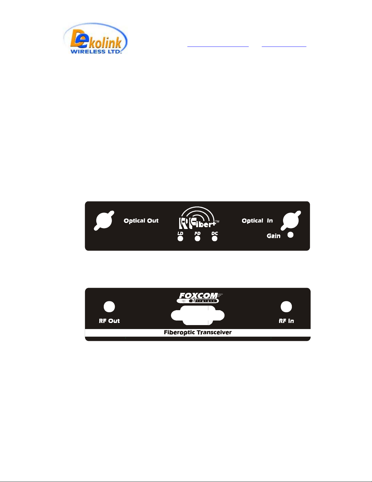
TM
The following drawings show sample front and rear panels of the RFiber+
(for WDM model there is only one optical in/out port).
unit
Fig. 2 : - RFiber+TM Front Panel
Fig. 3 : - RFiber+TM Rear Panel
On the Front Panel of the RFiber+
TM
unit (Fig 2.) are three LEDs. The LEDs should be
on when the unit is in use. The following table describes the LEDs.
rev3 08/03 Page 6 of 17
Page 7

Dekolink WIRELESS Ltd.
16 Bazel St. Qiryat-Arieh Petah-Tikva, Israel, 49510
Tel- 972-3-9180-180 Fax-972-3- 190-9180
e-mail: marketing@dekolink.com
web www.dekolink.com
LED Name LED Function
LD When ON - Indicates optical output power is within
product specifications.
PD When ON - Indicates optical power received is above
0.1mW.
DC Indicates when the power is on.
The “Gain” trimmer on the front panel is used to adjust signal level at the RF out of the
Rfiber+, especialy for optical loss compensation of the optical fiber.
2.5 Rfiber transmitter.
This is a fiber optic transmitter for Diversity path. Practically it is the transmit part of
Rfiber+ in a separate box.
2.6 MONITOR UNIT
The FBDA monitor performs the following functions:
a) Monitors the DC supply voltage of the FBDA. The fault LED illuminates when the
voltage is beyond the specified limits.
b) Monitors the current to each active element and the internal fan. If the current is
below or above the specified limits then a LED illuminates.
c) Monitor the optical receive signal using alarm output of the optical transceiver.
d) Monitors the Thermostat for high temperature alarm.
e) Provides automatic alarm function. Whenever any fault occurs or when the power
supply voltage is under it’s limit, the unit sends summarized alarm signal to the base
station via the Fiberoptic transmitter data port.
e) Provides self test for the alarm functions. The pushbutton switch on the Monitor
unit turns on all the alarm LEDs and initiates the summarized alarm.
rev3 08/03 Page 7 of 17
Page 8

Dekolink WIRELESS Ltd.
16 Bazel St. Qiryat-Arieh Petah-Tikva, Israel, 49510
Tel- 972-3-9180-180 Fax-972-3- 190-9180
e-mail: marketing@dekolink.com
web www.dekolink.com
Fig 4.: MONITOR OUTLINE
Fault list:
P.S. : power supply fault
FAN : Fan
ELISRA
BDA MONITOR
PWR. AMP : Downlink 50W AMP
DIV A : Diversity PATH
RFIBR DC : Rfibr dc current
UPLINK A .: Uplink amp
OPT. ALR .: Optical link alarm
HI. TEMP .: High temperature alarm
P.S.
DIV A.
.
PWR AMP
FAN
HI. TEMP
Rfiber DC
UPLINK A.
OPT. ALR
rev3 08/03 Page 8 of 17
Page 9

Dekolink WIRELESS Ltd.
16 Bazel St. Qiryat-Arieh Petah-Tikva, Israel, 49510
Tel- 972-3-9180-180 Fax-972-3- 190-9180
e-mail: marketing@dekolink.com
web www.dekolink.com
Fig 5.: FIBER LINK ALARMS
BLOCK DIAGRAM
RF ALARM UNIT
ALARM
VOLTAGE
DC IN
SENSOR
CURRENT
SENSOR
CURRENT
SENSOR
CURRENT
SENSOR
ALARM
ALARM
ALARM
DIV A.
DOWN LINK
P.A.
FAN
THERMO
STAT
DC IN
SUMMERIZED
ALARM
RELAY
ALARM
VOLTAGE
SENSOR
CURRENT
SENSOR
CURRENT
SENSOR
LOGIC
SENSOR
ALARM
ALARM
FIBER OPTIC TRANSCEIVER
OPTICAL
SENSOR
OPTICAL
ALARM
FIBER OPTIC
TRANSMITTER SERIAL
DATA INPUT
SUMMERIZED
ALARM
HIGH TEMP.
RFIBER
UPLINK AMP.
OPTICAL ALARM
OPTICAL FIBER LINK
TO BASE
rev3 08/03 Page 9 of 17
Page 10

Dekolink WIRELESS Ltd.
16 Bazel St. Qiryat-Arieh Petah-Tikva, Israel, 49510
Tel- 972-3-9180-180 Fax-972-3- 190-9180
e-mail: marketing@dekolink.com
web www.dekolink.com
2.7 POWER DISTRIBUTION UNIT
The power distribution unit acts as DC connection panel. It receives power from the
power supply and distributes it to the FBDA units.
It contains the following functions:
- Fuse and for the DC power coming from the AC power supply.
- Current sampler for the high power 50 Watt amplifier.
- distribution strip for various units.
2.8 POWER SUPPLY
This is a high efficiency switching power supply providing +28 VDC for the 50W
amplifier, and a +13.5 VDC for other units.
rev3 08/03 Page 10 of 17
Page 11

Dekolink WIRELESS Ltd.
16 Bazel St. Qiryat-Arieh Petah-Tikva, Israel, 49510
Tel- 972-3-9180-180 Fax-972-3- 190-9180
e-mail: marketing@dekolink.com
3 SPECIFICATIONS:
3.1 RF SECTION SPECIFICATIONS
web www.dekolink.com
Frequency Range
Uplink (RX, Rx1) Downlink (TX)
806-824 MHz 851-869 MHz
Passband Gain @ min attenuation 46 dB Nominal
Passband Ripple ± 1.0 dB typical
Noise Figure @+25°C
(optical loss less than 3 dB)
6.0 dB max @
max gain
Manual Attenuation Range 0 to 16 dB
continuous
N.A.
30 dB in 2 db
steps
Down-Link Output Composite Power ----------------- +40 dBm typ.
Down-Link 3rd Order Intermodulation
Products @two tones +37 dBm each
at Output
---------------
50 dBc min
Up-Link AGC Range 30 dB typ -----------------
Power Output at AGC Setting
0 ± 1 dBm -----------------
(Factory Set)
Up-Link 3rd Order Intermodulation
Products @two tones -3 dBm each at
F/O Transmitter Input
55 dBc typical
---------------
Impedance Level 50 Ohms
VSWR 1.5 : 1 max
rev3 08/03 Page 11 of 17
Page 12

Dekolink WIRELESS Ltd.
16 Bazel St. Qiryat-Arieh Petah-Tikva, Israel, 49510
Tel- 972-3-9180-180 Fax-972-3- 190-9180
e-mail: marketing@dekolink.com
web www.dekolink.com
3.2 FBDA ALARM SPECIFICATIONS
Remote Fault
Indication
(Summarized alarm)
Fault List : Power Supply Over-voltage or Under-voltage
Uplink Amplifier Over Current or Under Current
Downlink Power Amplifier Over Current or Under Current
FO Transceiver Over Current or Under Current
FO Receiver Power fall (Bad Optical Connection)
Fan Over Current or Under Current
High temperature
Electrical Fault
Indication LED
Fiber Optic
Connection Fault
Indication LED
3.3 MECHANICAL SPECIFICATIONS:
Relay Contact open for any fault. Relay closed for no
fault. Alarm is sent on the serial data link of the FO
transmitter
Illuminated LED on Monitor Box for each Electrical Fault
Illuminated LED on FO Transceiver when Optical
Connection is performing Correctly.
LED is OFF when FO Receiver Power falls.
Size : 400 x 400 x 300 mm approx.
RF Connectors : N-type Female
Weight : 30 kg. Approx.
Enclosure Type : Weather proof Enclosure
for Wall Mounted Installation(IP66).
Power Supply : 100 to 220 VAC / 2A
3.4 ENVIRONMENTAL CONDITIONS:
6.1 Operating temperature
6.2 Storage temperature
: - 20
: - 30
°
C to + 50°C
°
C to + 70°C
rev3 08/03 Page 12 of 17
Page 13

Dekolink WIRELESS Ltd.
16 Bazel St. Qiryat-Arieh Petah-Tikva, Israel, 49510
Tel- 972-3-9180-180 Fax-972-3- 190-9180
e-mail: marketing@dekolink.com
web www.dekolink.com
4. RF EXPOSURE WARNING
In order to satisfy the FCC RF exposure requirements, you must ensure that the
installation complies with the following:
The antenna is connected via cable that has typical 1~10 dB attenuation (depends on
the length of the cable) to the FBDA MOBILE port.
There are two applications: Outdoor and Indoor.
In the case of Outdoor the type of antenna is omnidirectional (isotropic) with 0 to 2 dBi
typical gain, or wide beam with up to 3 dBi gain, and is installed on a mast to cover
shadowed, outdoor, area. This antenna must be installed to provide a minimum
separation distance of 1 m (100 cm) from persons within the area
In the case of Indoor coverage the power is split to several, omnidirectional (isotropic)
antenna with 0 to 2 dBi typical gain, and distributes to different indoor areas (in
building floors, tunnels, basements, parking lots, shopping centers etc.). Typical
specifications: gain: 2 dBi, VSWR: better than 2:1 , Impedance: 50 ohm. At least 5
such antenna must be connected to the BDA using cables and splitters. In this case
the max. EIRP from each antenna will not exceed 3W so that the minimum required
separation distance from persons within the area is 20cm.
Less separation is needed if the power is divided into more than 5 antenna covering
many floors or areas.
rev3 08/03 Page 13 of 17
Page 14
Dekolink WIRELESS Ltd.
16 Bazel St. Qiryat-Arieh Petah-Tikva, Israel, 49510
Tel- 972-3-9180-180 Fax-972-3- 190-9180
e-mail: marketing@dekolink.com
web www.dekolink.com
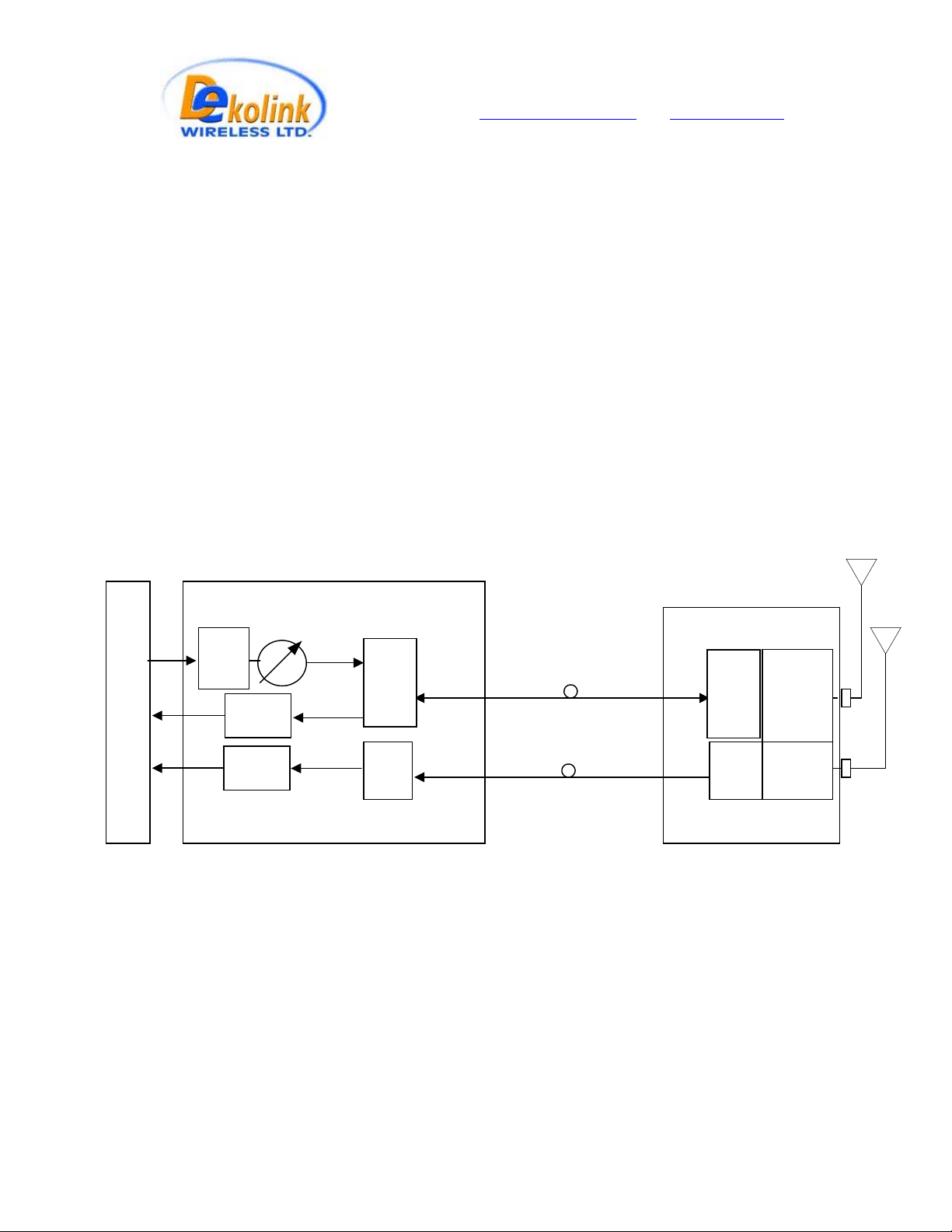
BTS
Tx
Rx
Rx1
High
pwr
ATTN.
30 dB
ATTN.
30 dB
ATTN.
30 dB
ATTN
FBIU
RF IN
(MAX. 0dBm)
RF Out
RF Out
FIBEROPTIC CABLE
RUN UP TO 20Km
F/O+
WDM
F/O
optical in/out
optical in
optical in/out
FBDA SYSTEM BLOCK DIAGRAM
Mobile ANT.
FBDA
F/O+
WDM
RF
section
F/O
optical Out
rev3 08/03 Page 14 of 17
Page 15
Dekolink WIRELESS Ltd.
16 Bazel St. Qiryat-Arieh Petah-Tikva, Israel, 49510
Tel- 972-3-9180-180 Fax-972-3- 190-9180
e-mail: marketing@dekolink.com
web www.dekolink.com
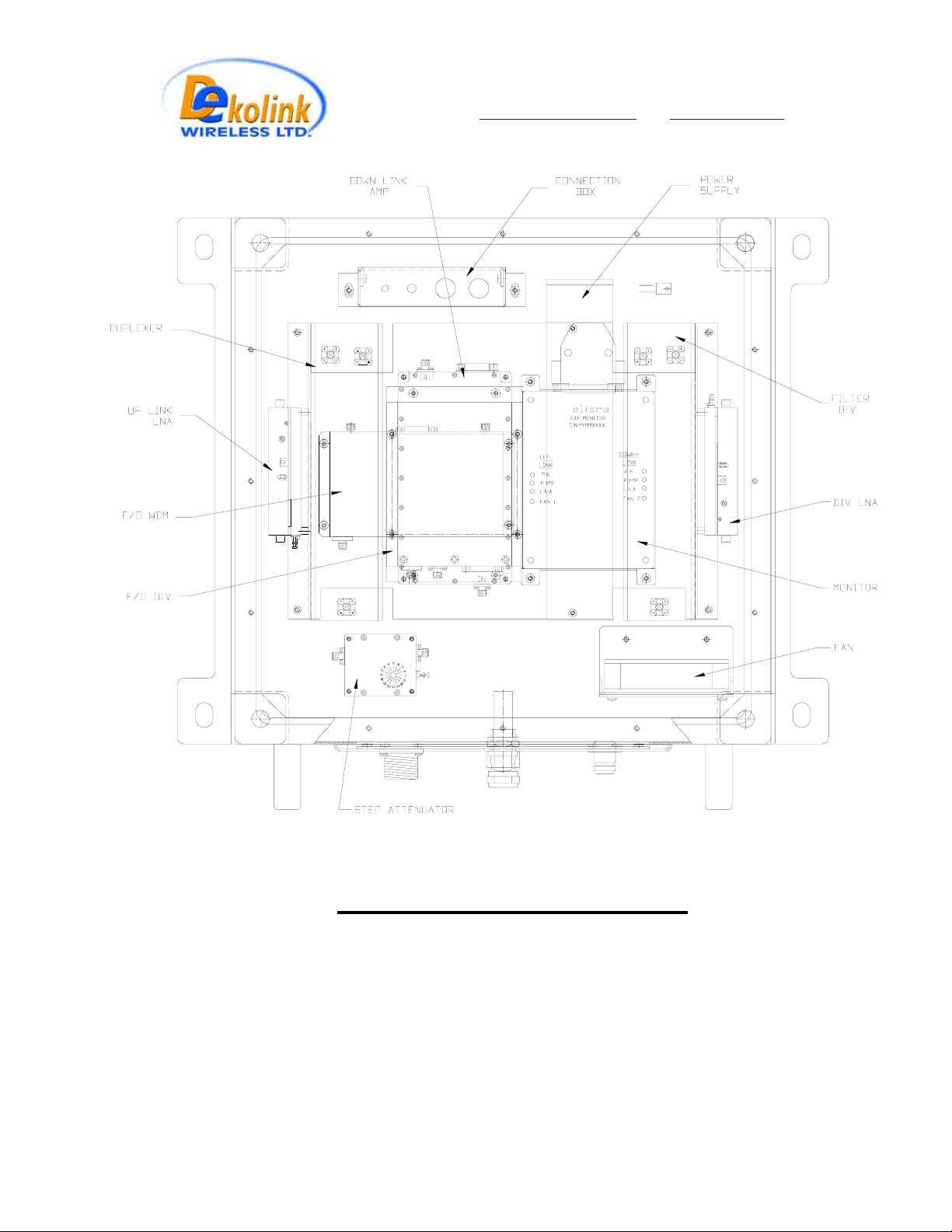
Fig. 7:MECHANICAL LAYOUT
rev3 08/03 Page 15 of 17
Page 16

Dekolink WIRELESS Ltd.
16 Bazel St. Qiryat-Arieh Petah-Tikva, Israel, 49510
Tel- 972-3-9180-180 Fax-972-3- 190-9180
e-mail: marketing@dekolink.com
web www.dekolink.com
Fig. 8: MECHANICAL OUTLINE
rev3 08/03 Page 16 of 17
Page 17

Dekolink WIRELESS Ltd.
16 Bazel St. Qiryat-Arieh Petah-Tikva, Israel, 49510
Tel- 972-3-9180-180 Fax-972-3- 190-9180
e-mail: marketing@dekolink.com
web www.dekolink.com
DEKOLINK WIRELESS
IMITED
L
ARRANTY
W
Dekolink Wireless [Ltd.] (“Dekolink”), manufacturer of this product (the “Product”) warrants to
the original purchaser (“Purchaser”) that the Product is free from defects in materials and
workmanship for a term that ends on the earlier of twelve (12) months from the date of
activation of the Product or fifteen (15) months from the date of shipment of the Product by
Dekolink. The obligations of Dekolink under this warranty shall be limited solely to the repair or
exchange or giving credit for, at the option of Dekolink, any Product that may prove defective in
accordance with evidence satisfactory to Dekolink. Any repair or replacement of the Product by
Dekolink shall not extend the original warranty period. This warranty is exclusive to the original
Purchaser and is not assignable.
This warranty applies only upon the condition that the Product has been installed, maintained and
operated under conditions of normal use. The provisions of this warranty shall not apply if, in
Dekolink’s judgment, the Product has been subject to misuse or neglect, damaged in an accident or
by act of vandalism, or repaired or altered in any way that adversely affects its performance or
reliability.
To obtain warranty service, Purchaser may, upon the prior written authorization of Dekolink or its
authorized service representative, return the defective Product to Dekolink’s authorized service
center. All shipping and insurance charges are the sole responsibility of Purchaser and are not
included in this warranty.
Dekolink expressly excludes and disclaims all other warranties, including but not limited to any
warranties of merchantability or fitness for a particular purpose.
Dekolink shall in no event be liable for any special, indirect, incidental, consequential or punitive
damages or for loss, damage, or expense, including loss of use, profits, revenue, or goodwill,
directly or indirectly arising from purchaser’s use or inability to use the merchandise, or for loss
or destruction of other property or from any other cause, even if Dekolink has been advised of
the possibility of such damage. Some states do not allow the exclusion or limitation of incidental
or consequential damages so these limitations may not apply under certain circumstances.
The liability of Dekolink shall in no event exceed an amount equivalent to the purchase price paid
by the purchaser for the defective product.
This warranty shall not be extended, altered or varied except by a written instrument duly signed
by Dekolink.
rev3 08/03 Page 17 of 17
 Loading...