

Page 1
Dekolink WIRELESS Ltd.
16 Bazel St. Qiryat-Arieh Petah-Tikva, Israel, 49510
Tel- 972-3-9180-180 Fax-972-3- 190-9180
e-mail: marketing@decolink.com
web www.decolink.com
INSTALLATION AND
OPERATING INSTRUCTIONS
FOR
CELLULAR A+B
Fiber-optic REPEATER SYSTEM
50W WITH DIVERSITY
& FiberopticBase Interface Unit
Page
1 of 1
FO-800AB-50W SYS.doc
Page 2

Dekolink WIRELESS Ltd.
16 Bazel St. Qiryat-Arieh Petah-Tikva, Israel, 49510
Tel- 972-3-9180-180 Fax-972-3- 190-9180
e-mail: marketing@decolink.com
web www.decolink.com
TABLE OF CONTENTS
PARA No. PARAGRAPH PAGE No.
1. OVERVIEW 3
1.1 FBIU 3
1.2 FBDA 4
2. SUBSYSTEM DESCRIPTION 5
2.1 FBDA 5
2.2 FBIU 5
2.2.1 FIBEROPTIC TRANSCEIVER 5
2.2.2 DUPLEXER 5
2.2.3 ATTENUATOR 5
3 SYSTEM SPECIFICATIONS 7
3.1 RF SPECIFICATIONS 7
3.2 FBDA ALARM SPECIFICATIONS 8
3.3 MECHANICAL SPECIFICATIONS 8
3.4 ENVIRONMENTAL CONDITIONS 8
4 INSTALLATION PROCEDURE 9
4.1 FIBER OPTIC LINK ASSEMBLY 9
4.2 DOWNLINK CALLIBRATION 9
4.3 UPLINK CALLIBRATION 9
4.4 SYSTEM ASSEMBLY 10
LIST OF FIGURES
Fig No. Fig. name Page No.
1 FIBEROPTIC REPEATER
SYSTEM BLOCK DIAGRAM
4
2 FBIU RF BLOCK DIAGRAM 6
3 FBIU MECHANICAL LAYOUT 11
Page
2 of 2
FO-800AB-50W SYS.doc
Page 3

Dekolink WIRELESS Ltd.
16 Bazel St. Qiryat-Arieh Petah-Tikva, Israel, 49510
Tel- 972-3-9180-180 Fax-972-3- 190-9180
e-mail: marketing@decolink.com
web www.decolink.com
1. OVERVIEW:
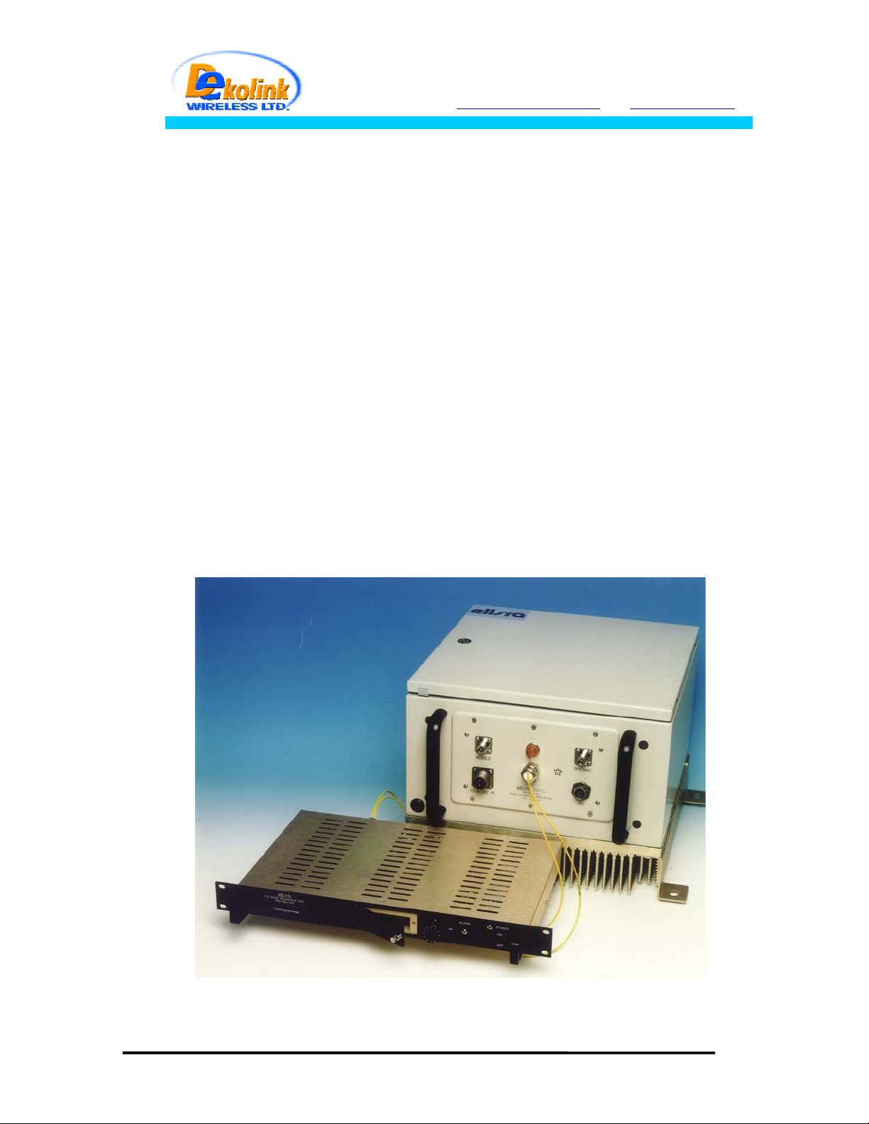
The Fiber optic repeater system is an excellent solution for BTS coverage
extension by means of Fiber optic link and remote high power RF head.
The system consists of two conversion boxes;
- FBIU (Fiberoptic Base Interface Unit)
- FBDA (Fiber optic Bi Directional Amplifier)
Two fibers, one for main path, uplink and downlink direction and one in
diversity uplink direction connect the FBIU to the FBDA. Using fiberoptic
cable allows long distance transmission, up to 20 Km.
1.1 FBIU
The FBIU is installed near the BTS and is connected to the BTS by RF
cables. A Fiberoptic transceiver converts the Downlink RF signals to optical
signals and the uplink optical signal to RF. A high power attenuator is used
as power adjustment between BTS Tx power and Fiberoptic transceiver
requirements. A separate attenuator is used for Rx direction.
The Diversity path is connected through Fiberoptic receiver and fixed
attenuator to the Diversity receiver.
Page
3 of 3
FO-800AB-50W SYS.doc
Page 4
Dekolink WIRELESS Ltd.
16 Bazel St. Qiryat-Arieh Petah-Tikva, Israel, 49510
Tel- 972-3-9180-180 Fax-972-3- 190-9180
e-mail: marketing@decolink.com
web www.decolink.com
1.2 FBDA
The FBDA is installed near the area to be covered and is connected to the
mobile antenna. A Fiberoptic transceiver converts the Downlink optical
signals to RF signals and the uplink RF signals to optical signals. A duplexer
in the FBDA separates the uplink and downlink signals thus enabling the use
of the same antenna for receiving and transmitting. The duplexer has sharp
out of band attenuation for better isolation between the receiving and
transmitting paths and for reduction of out of band interfering signals. A high
power amplifier in the downlink path produces high RF power to the antenna.
A LNA (low noise amplifier) is used to drive the uplink signals from the
antenna to the Fiberoptic transceiver input to maintain reasonable NF (noise
figure) in the uplink path. The FBDA contains a monitoring unit to monitor the
operation of the active elements inside the FBDA. Whenever a fault occurs
an ALARM signal is sent to the FBIU.
BTS
For diversity applications the uplink path is duplicated using separate
antenna, filter, LNA and Fiberoptic transmitter.
BASE SITE
FBDA
F/O+
WDM
RF
section
F/O
Tx
Rx
Rx1
FIBEROPTIC CABLE
High pwr
ATTN.
ATTN.
ATTN.
RF IN
(MAX. 0dBm)
RF Out
RF Out
F/O+
WDM
F/O
optical in/out
optical in
RUN UP TO 20Km
optical in/out
optical Out
Fig. 1 : Fiber-optic REPEATER SYSTEM BLOCK DIAGRAM
Mobile ANT.
Page
4 of 4
FO-800AB-50W SYS.doc
Page 5

Dekolink WIRELESS Ltd.
16 Bazel St. Qiryat-Arieh Petah-Tikva, Israel, 49510
Tel- 972-3-9180-180 Fax-972-3- 190-9180
e-mail: marketing@decolink.com
2. SUBSYSTEM DESCRIPTION:
web www.decolink.com
2.1 FBDA
Please refer to installation and operation instructions for
FBDA-800AB-50W-DIV
2.2 FBIU
The FBIU is the BTS interface of the system. It includes Fiberoptic
transceiver, duplexer and attenuator for main uplink and downlink , uplink
diversity Fiberoptic transmitter receiver and attenuator, and power supply.
2.2.1Fiberoptic transceiver
The Fiberoptic transceiver converts the signal form RF to optical in the
downlink direction and from optical signal to RF in the uplink direction.
2.2.2 DUPLEXER
The duplexer separates the uplink and downlink signals to anable one RF
cable connection to the BTS. In case of separate connections for Rx and Tx ,
the duplexer is not required.
2.2.3 ATTENUATOR
Assuming that the output power of BTS is +30dBm, a 30 dB high power
external attenuator is required. In practice, more attenuation can be added
Page
5 of 5
FO-800AB-50W SYS.doc
Page 6

Dekolink WIRELESS Ltd.
16 Bazel St. Qiryat-Arieh Petah-Tikva, Israel, 49510
Tel- 972-3-9180-180 Fax-972-3- 190-9180
e-mail: marketing@decolink.com
web www.decolink.com
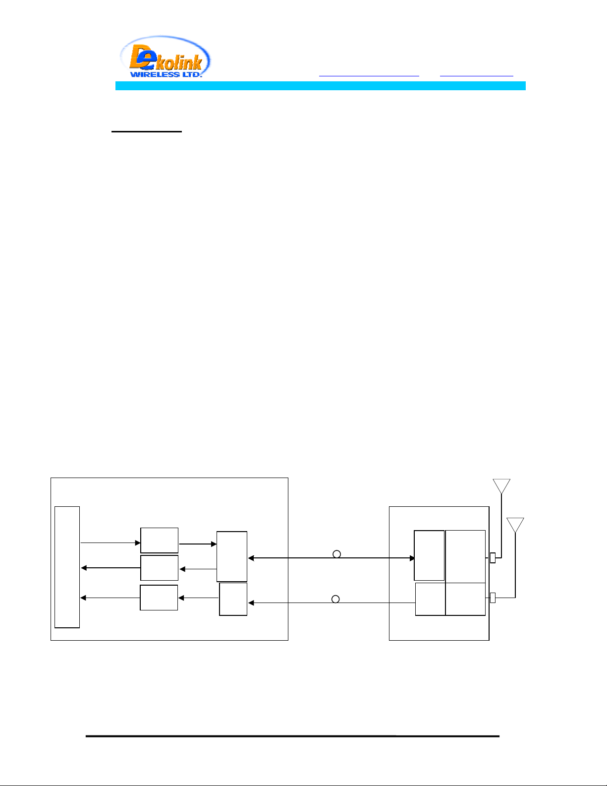
for different system setting. In case of separate connections for Rx and Tx ,
separate attenuators for Rx and Tx should be used.
(MAX. 0dBm)
RF Out
F/O
RF IN
F/O+
WDM
optical in
optical in/out
VAR. ATTN.
High pwr ATTN.
ATTN.
TO BTS
ATTN.
RF Out
FIG 2: FBIU RF BLOCK DIAGRAM
(without duplexer)
Page
6 of 6
FO-800AB-50W SYS.doc
Page 7

Dekolink WIRELESS Ltd.
16 Bazel St. Qiryat-Arieh Petah-Tikva, Israel, 49510
Tel- 972-3-9180-180 Fax-972-3- 190-9180
e-mail: marketing@decolink.com
3 . SYSTEM SPECIFICATIONS:
3.1 RF SPECIFICATIONS
(optical loss adjusted to 0dBm, all attenuators 30 dB)
web www.decolink.com
Frequency Range
Uplink (RX, DIV) Downlink (TX)
824-849 MHz 869-894 MHz
Passband Gain @ min attenuation 16 dB Nom. 10dB Nom.
Passband Ripple ± 1.0 dB typical
Manual Attenuation Range 0 to 16 db cont.
(FBDA side)
Noise Figure @+25°C
6.0 dB max N.A.
0-10 dB in 1dB steps
(FBIU side)
(optical loss less than 3 dB)
Up-Link 3rd Order Intermodulation
55 dBc typical N.A.
Products @two tones -3 dBm each
at FBIU Rfiber Output
Down-Link 3rd Order Intermodulation
Products @two tones +37 dBm each at
Output
---------------
50 dBc min.
AGC Power Level(Factory Set) 0 ± 1.0 dBm nom. 40±1 dBm
AGC Range 30 dB min 10
Impedance Level 50 Ohms
VSWR In 1.5 : 1 typ
VSWR Out 2.0 : 1 typ
Page
7 of 7
FO-800AB-50W SYS.doc
Page 8

Dekolink WIRELESS Ltd.
16 Bazel St. Qiryat-Arieh Petah-Tikva, Israel, 49510
Tel- 972-3-9180-180 Fax-972-3- 190-9180
e-mail: marketing@decolink.com
web www.decolink.com
3.2 FBDA ALARM SPECIFICATIONS
Remote Fault Indication
(Summarized alarm)
Fault List : Power Supply Over-voltage or Under-voltage
Uplink Amplifier Over Current or Under Current
Downlink Power Amplifier Over Current or Under Current
FO Transceiver Over Current or Under Current
FO Receiver Power fall (Bad Optical Connection)
Fan Over Current or Under Current
Electrical Fault
Indication LED
Fiber Optic Connection
Fault Indication LED
FBIU alarm output Dtyp 9pin male, N.C. relay contact between pin 2 and pin
3.3 MECHANICAL SPECIFICATIONS:
FBDA FBIU
Alarm is sent on the serial data link of the FO transmitter
to FBIU
Illuminated LED on Monitor Box for each Electrical Fault
Illuminated LED on FO Transceiver when Optical
Connection is performing Correctly.
LED is OFF when FO Receiver Power falls.
4, open for active alarm + Illuminated LED on front panel.
Size 400 x 400 x 300 mm approx. 19” 1Ux250mm
Weight 25 kg. Approx. 3 kg. Approx.
Type Weatherproof Enclosure for
In door, rack mount
Wall Mounted Installation
Power Supply 110 VAC / 2A or 220VAC/1A 110/220VAC
(0PTIONAL -48V DC 1A)
3.4 ENVIRONMENTAL CONDITIONS:
Operating temperature
Storage temperature
Weatherproof conditions Protected to IP65 (FBDA only)
C to + 50°C
- 30°
C to + 70°C
- 30°
Page
8 of 8
FO-800AB-50W SYS.doc
Page 9

Dekolink WIRELESS Ltd.
16 Bazel St. Qiryat-Arieh Petah-Tikva, Israel, 49510
Tel- 972-3-9180-180 Fax-972-3- 190-9180
e-mail: marketing@decolink.com
web www.decolink.com
4. INSTALLATION PROCEDURE
4.1 Fiber Optic Link Assembly:(both FBDA and FBIU)
4.1.1 Insert main optical fiber trough the Fiber In/out hole on the FBDA
panel and connect it to the Optical In/out connector on the Fiberoptic
transceiver. On the FBIU connect the optical fiber to the Optical In/out
connector on the Fiberoptic transceiver.
4.1.2 Insert diversity optial fiber trough the Fiber in/out hole on the FBDA
panel and connect it to the Optical out connector on the Fiberoptic
transmitter. On the FBIU connect the diversity optical fiber to the Optical In
connector on the Fiberoptic receiver.
4.2 Downlink calibration:
4.2.1 Connect Spectrum analyzer through High Power Attenuator of 40 dB to
the Antenna port of the FBDA.
4.2.2 Inject (+20) dBm signal at 880 MHz from the FBIU Tx antenna through
the optical link.
4.2.3 Adjust Gain on the Fiberoptic transceiver front panel in the FBDA so
that RF power at the output is +30dBm.
4.3 Uplink calibration:(both main and diversity path)
4.3.1 Connect Spectrum analyzer to the Rx port of the FBIU.
4.3.2 Inject (–60) dBm signal at 835 MHz from the antenna port on the FBDA
side through the optical link.
4.3.3 Adjust Gain on the Fiberoptic transceiver in the FBIU so that RF power
at the output is -44 dBm.
4.3.4 Repeat the above with the diversity path.
Page
9 of 9
FO-800AB-50W SYS.doc
Page 10

Dekolink WIRELESS Ltd.
16 Bazel St. Qiryat-Arieh Petah-Tikva, Israel, 49510
Tel- 972-3-9180-180 Fax-972-3- 190-9180
e-mail: marketing@decolink.com
web www.decolink.com
4.4 System assembly:
4.4.1 Connect BTS Tx to Tx antenna port on FBIU. (Another 10dB attenuator
can be connected to the RF IN port of the Fiberoptic transceiver in the FBIU
and the Rotary Attenuator on the FBIU front panel adjusted slightly for
system performance optimization).
4.4.2 Connect Spectrum analyzer or Power Meter through High Power
Attenuator of 40 dB to the Antenna port of the FBDA.
4.4.3 Turn the system ON, make sure that output power of BTS is no more
than +30dBm. In case of higher power, higher attenuation is needed
between BASE and FBIU.
4.4.4 Adjust Gain on the Fiberoptic transceiver front panel in the FBDA so
that RF power at the output is +40±1dBm.
4.4.5 Connect diversity RX port on FBIU to the diversity receiver in the BTS.
Connect RX port on FBIU to the Rx port in the BTS
4.4.6 Turn power off. Disconnect Spectrum analyzer and attenuator from
Antenna port on the FBDA and connect Mobile Antenna and Diversity to the
FBDA.
4.4.7 Turn power on.
Page
10 of 10
FO-800AB-50W SYS.doc
Page 11
Dekolink WIRELESS Ltd.
16 Bazel St. Qiryat-Arieh Petah-Tikva, Israel, 49510
Tel- 972-3-9180-180 Fax-972-3- 190-9180
e-mail: marketing@decolink.com
web www.decolink.com
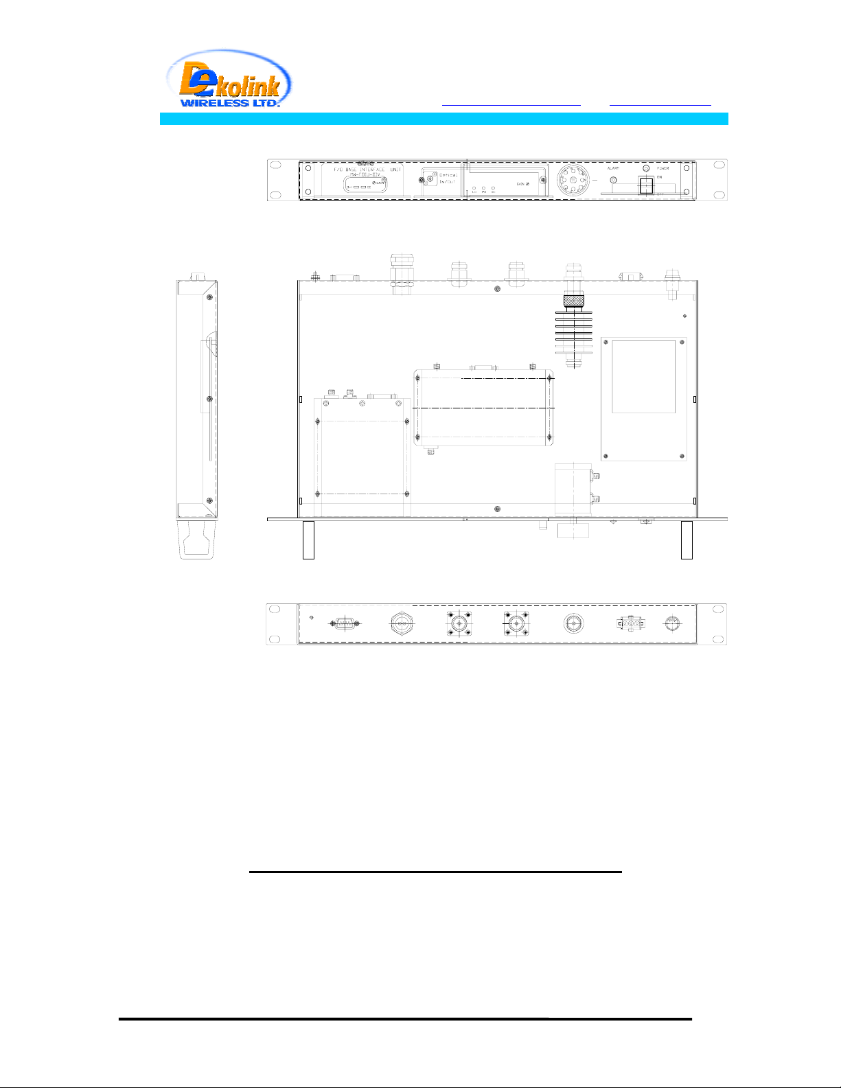
Fig. 3: FBIU MECHANICAL LAYOUT
Page
11 of 11
FO-800AB-50W SYS.doc
 Loading...