

Dekolink Wireless FBDA800AB50WD Installtion and operation instructions for amplifier with diversity
Page 1
Dekolink WIRELESS Ltd.
16 Bazel St. Qiryat-Arieh Petah-Tikva, Israel, 49510
Tel- 972-3-9180-180 Fax-972-3- 190-9180
e-mail: marketing@decolink.com
web www.decolink.com
INSTALLATION and OPERATION
INSTRUCTIONS
FOR
FiberLink
BI-DIRECTIONAL AMPLIFIER
WITH DIVERSITY
MW-FBDA-800AB-50W-DIV
Page 1 of 15 FBDA-800AB-50wDIV-INSTL.doc
Page 2

Dekolink WIRELESS Ltd.
16 Bazel St. Qiryat-Arieh Petah-Tikva, Israel, 49510
Tel- 972-3-9180-180 Fax-972-3- 190-9180
e-mail: marketing@decolink.com
web www.decolink.com
TABLE OF CONTENTS
PARA No. PARAGRAPH PAGE No.
1. OVERVIEW 3
2. COMPONENT DESCRIPTION 5
2.1 DUPLEXER 5
2.2 UPLINK AMPLIFIER 5
2.3 35 WATT DOWNLINK POWER AMPLIFIER 5
2.4
2.5 RFIBER TRANSMITTER 7
2.6 MONITOR UNIT 7
2.7 DISTRIBUTION UNIT 10
2.8 POWER SUPPLY 10
3 ELECTRICAL SPECIFICATIONS 11
3.1 RF SPECIFICATIONS 11
3.2 FBDA ALARM SPECIFICATIONS 12
3.3 MECHANICAL SPECIFICATIONS 12
3.4 ENVIRONMENTAL CONDITIONS 12
4 RF EXPOSURE WARNING 13
Fiberoptic transceiver
5
LIST OF FIGURES
Fig No. Fig. name Page No.
1 FBDA RF BLOCK DIAGRAM
2 RFIBER FRONT PANEL
3 RFIBER REAR PANEL
4 MONITOR OUTLINE
4
6
6
8
5 FIBERLINK ALARM BLOCK DIAGRAM 9
6 FBDA SYSTEM BLOCK DIAGRAM 13
7 MECHANICAL LAYOUT 14
8 MECHANICAL OUTLINE 15
Page 2 of 15 FBDA-800AB-50wDIV-INSTL.doc
Page 3

Dekolink WIRELESS Ltd.
16 Bazel St. Qiryat-Arieh Petah-Tikva, Israel, 49510
Tel- 972-3-9180-180 Fax-972-3- 190-9180
e-mail: marketing@decolink.com
web www.decolink.com
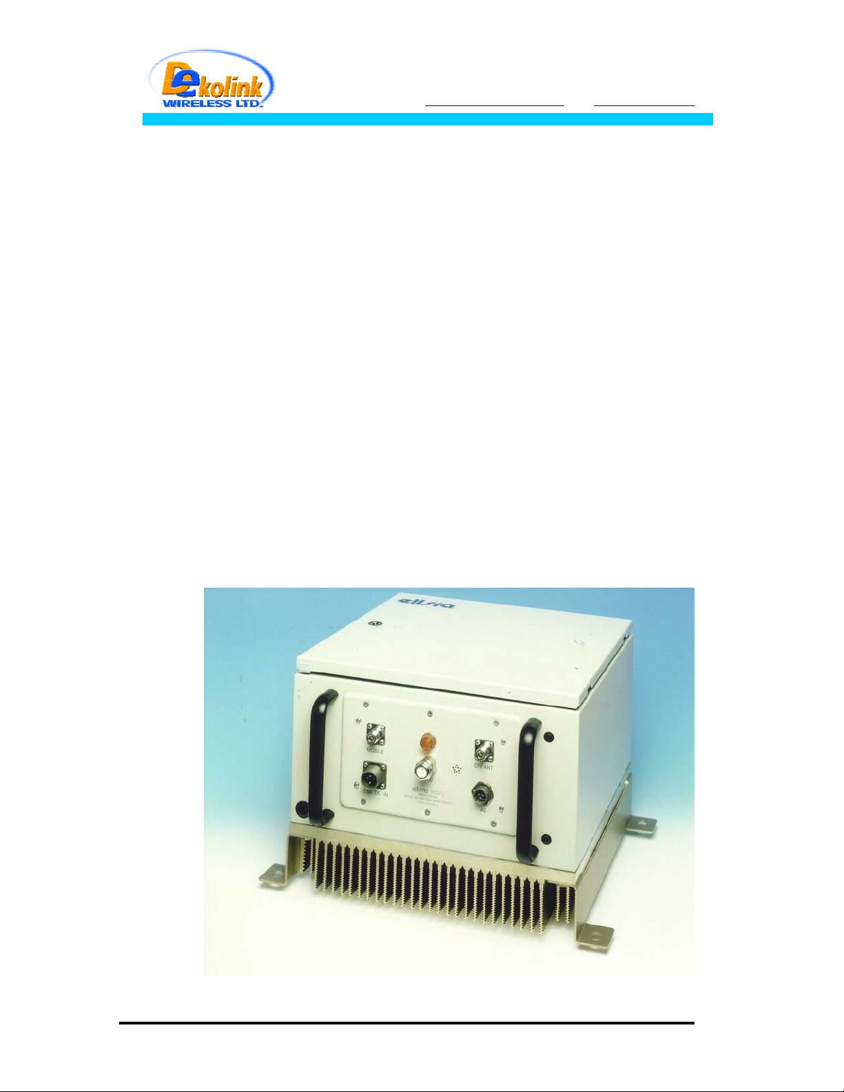
1. OVERVIEW:
The FBDA is an interface unit between optical signals carrying RF information, and RF
antennas covering a defined user area. The system consists of uplink path and
downlink path and an additional uplink path for diversity.
The uplink path receives RF signals from the Mobile antenna amplifies them and the
Rfiber+ converts them to optical signals. These optical signals are sent to the BTS.
The downlink path receives optical signals from the BTS to the Rfiber+, converts them
to RF signals and amplifies these signals using a high power amplifier. The Mobile
antenna transmits these RF signals.
A duplexing filter separates the frequencies of uplink path from the downlink path
enabling the use of the same antenna for receiving and transmitting. The FBDA
provides about 46 dB RF gain in both directions.
Both optical signals for Uplink and Downlink are carried on a single fiber using WDM.
Downlink gain can be adjusted using a trim pot on the Rfiber+ front panel for proper
output power.
Uplink gain can be adjusted by 16 dB continuous trim pot.
The downlink path uses a 50 Watt power amplifier while the uplink uses an AGC
amplifier to drive the uplink F/O transmitter. The AGC is set to 0 dBm, which is the
max power required by the F/O transmitter.
For diversity reasons there is an additional Uplink path consisting of Cavity band pass
filter, AGC amplifier, and Fiber optic transmitter. The optical signal of this path is
transferred via an additional fiber to the base station.
Page 3 of 15 FBDA-800AB-50wDIV-INSTL.doc
Page 4
Dekolink WIRELESS Ltd.
16 Bazel St. Qiryat-Arieh Petah-Tikva, Israel, 49510
Tel- 972-3-9180-180 Fax-972-3- 190-9180
e-mail: marketing@decolink.com
web www.decolink.com
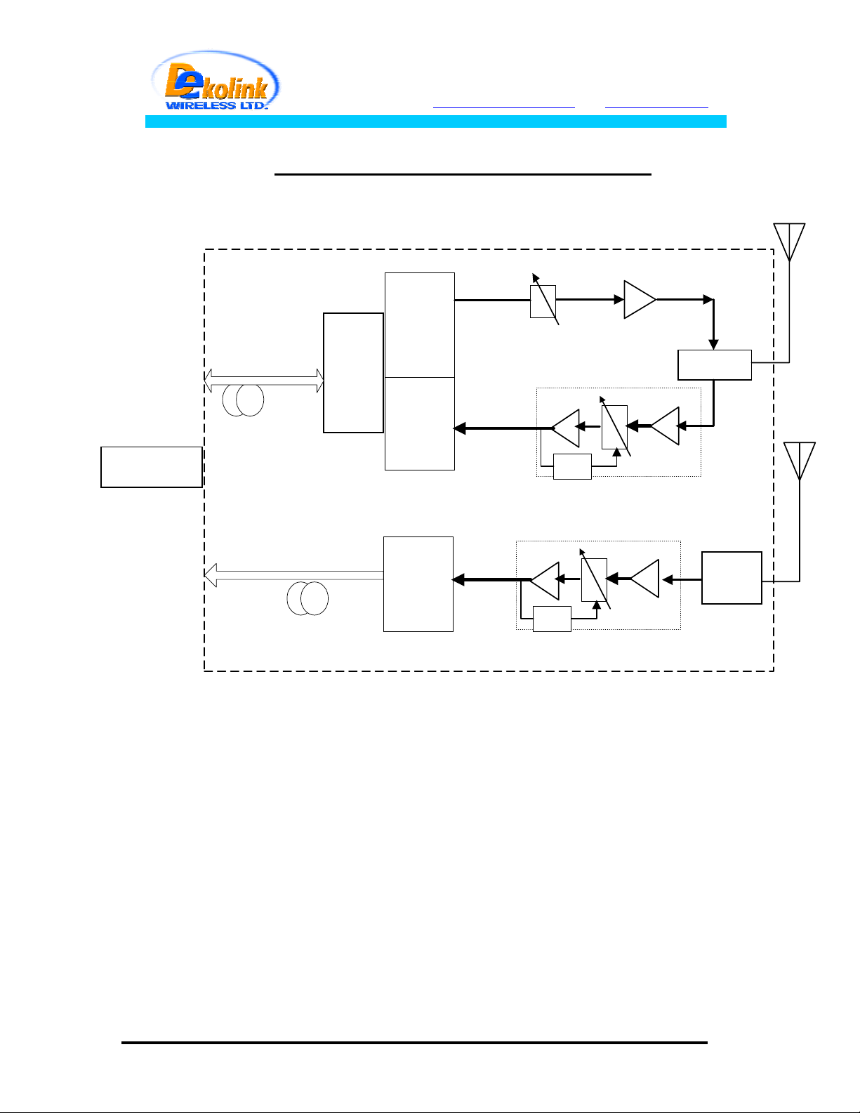
TO BTS
Fig. 1 : FBDA RF BLOCK DIAGRAM
Optical
Fiber
Downlink / Uplink
Optical
Fiber
Uplink
(diversity)
WDM
Fiberoptic
Receiver
Fiberoptic
Transmitter
Fiberoptic
Transmitter
UP LINK
AMP
UP LINK
AMP
Step
Attenuator
AGC
AGC
Down link Power
Amplifier
TX
Duplexer
RX
Variable
Attenuator
Rx1
Filter
Variable
Attenuator
Page 4 of 15 FBDA-800AB-50wDIV-INSTL.doc
Page 5

Dekolink WIRELESS Ltd.
16 Bazel St. Qiryat-Arieh Petah-Tikva, Israel, 49510
Tel- 972-3-9180-180 Fax-972-3- 190-9180
e-mail: marketing@decolink.com
web www.decolink.com
2. COMPONENTS DESCRIPTION:
2.1 DUPLEXER(x2)
The duplexer serves to frequency separate uplink signals from downlink signals. The
duplexer has sharp out of band attenuation for better isolation between the receiving
and transmitting paths and for better rejection of interfering signal in the air. In the
Diversity path only the Rx part of the duplexer is used.
2.2 UPLINK AMPLIFIER(both Rx pathes)
The uplink amplifier is a low noise, 45dB gain unit. The amplifier contains AGC control
circuitry. When a high power signal is received the automatic level control detects it
and reduces the gain so that the output power of the amplifier is constant. The AGC
function limits the signal at the Fiberoptic transmitter input when high power signals
are received while keeping high gain when low power signals are received.
The LED on the amplifier illuminates when the power output of the amplifier exceeds
the AGC power set limit (when the AGC is either ON or OFF).
The Switch on the RF amplifier enables the AGC function. If the AGC is disabled then
the amplifier gives maximum gain for any input.
The AGC level is factory set to 0 dBm and AGC is set to ON, to prevent high power
damage at the Rfiber+ input.
2.3 50 WATT DOWNLINK POWER AMPLIFIER
This is the downlink power amplifier. It can drive 40 dBm composite power to the
MOBILE antenna. A thermostat attatched to this amplifier turns on TEMP alarm when
the temperature exceeds 80° C.
2.4 Fiberoptic to RF transceiver
The RFiber+TM product is a transceiver that includes a transmitter and receiver unit.
The transmitter converts the RF signals into light wave signals, which are then sent
over fiberoptic cables. The receiver converts light wave signals back to RF
The model in use is a wide band product in the 0.08-1 GHz frequency range and it
includes a WDM module to enable use of one fiber for Tx and Rx signals.
Page 5 of 15 FBDA-800AB-50wDIV-INSTL.doc
Page 6

Dekolink WIRELESS Ltd.
16 Bazel St. Qiryat-Arieh Petah-Tikva, Israel, 49510
Tel- 972-3-9180-180 Fax-972-3- 190-9180
e-mail: marketing@decolink.com
web www.decolink.com
The RFiber+TM main features are:
1. Protocol transparency; i.e. any standard can be faithfully transmitted.
2. An optional serial port (RS232) is installed into each unit. This port allows
data communication over the same fiberoptic cable.
3. Max. input RF power for normal operation – 0dBm.
4. Manual Gain Control is standard in receiver to compensate for optical loss
across the fiber.
TM
The following drawings show sample front and rear panels of the RFiber+
(for WDM model there is only one optical in/out port).
unit
Fig. 2 : - RFiber+TM Front Panel
Fig. 3 : - RFiber+TM Rear Panel
On the Front Panel of the RFiber+
TM
unit (Fig 2.) are three LEDs. The LEDs should be
on when the unit is in use. The following table describes the LEDs.
Page 6 of 15 FBDA-800AB-50wDIV-INSTL.doc
Page 7

Dekolink WIRELESS Ltd.
16 Bazel St. Qiryat-Arieh Petah-Tikva, Israel, 49510
Tel- 972-3-9180-180 Fax-972-3- 190-9180
e-mail: marketing@decolink.com
web www.decolink.com
LED Name LED Function
LD When ON - Indicates optical output power is within
product specifications.
PD When ON - Indicates optical power received is above
0.1mW.
DC Indicates when the power is on.
The “Gain” trimmer on the front panel is used to adjust signal level at the RF out of the
Rfiber+, especialy for optical loss compensation of the optical fiber.
2.5 Rfiber transmitter.
This is a fiber optic transmitter for Diversity path. Practically it is the transmit part of
Rfiber+ in a separate box.
2.6 MONITOR UNIT
The FBDA monitor performs the following functions:
a) Monitors the DC supply voltage of the FBDA. The fault LED illuminates when the
voltage is beyond the specified limits.
b) Monitors the current to each active element and the internal fan. If the current is
below or above the specified limits then a LED illuminates.
c) Monitor the optical receive signal using alarm output of the optical transceiver.
d) Monitors the Thermostat for high temperature alarm.
e) Provides automatic alarm function. Whenever any fault occurs or when the power
supply voltage is under it’s limit, the unit sends summarized alarm signal to the base
station via the Fiberoptic transmitter data port.
e) Provides self test for the alarm functions. The pushbutton switch on the Monitor
unit turns on all the alarm LEDs and initiates the summarized alarm.
Page 7 of 15 FBDA-800AB-50wDIV-INSTL.doc
Page 8

Dekolink WIRELESS Ltd.
16 Bazel St. Qiryat-Arieh Petah-Tikva, Israel, 49510
Tel- 972-3-9180-180 Fax-972-3- 190-9180
e-mail: marketing@decolink.com
web www.decolink.com
Fig 4.: MONITOR OUTLINE
Fault list:
P.S. : power supply fault
FAN : Fan
ELISRA
BDA MONITOR
PWR. AMP : Downlink 50W AMP
DIV A : Diversity PATH
RFIBR DC : Rfibr dc current
UPLINK A .: Uplink amp
OPT. ALR .: Optical link alarm
HI. TEMP .: High temperature alarm
P.S.
DIV A.
.
PWR AMP
FAN
HI. TEMP
Rfiber DC
UPLINK A.
OPT. ALR
Page 8 of 15 FBDA-800AB-50wDIV-INSTL.doc
Page 9

Dekolink WIRELESS Ltd.
16 Bazel St. Qiryat-Arieh Petah-Tikva, Israel, 49510
Tel- 972-3-9180-180 Fax-972-3- 190-9180
e-mail: marketing@decolink.com
web www.decolink.com
Fig 5.: FIBER LINK ALARMS
BLOCK DIAGRAM
RF ALARM UNIT
ALARM
VOLTAGE
DC IN
SENSOR
CURRENT
SENSOR
CURRENT
SENSOR
CURRENT
SENSOR
ALARM
ALARM
ALARM
DIV A.
DOWN LINK
P.A.
FAN
THERMO
STAT
DC IN
SUMMERIZED
ALARM
RELAY
ALARM
VOLTAGE
SENSOR
CURRENT
SENSOR
CURRENT
SENSOR
LOGIC
SENSOR
ALARM
ALARM
FIBER OPTIC TRANSCEIVER
OPTICAL
SENSOR
OPTICAL
ALARM
FIBER OPTIC
TRANSMITTER SERIAL
DATA INPUT
SUMMERIZED
ALARM
HIGH TEMP.
RFIBER
UPLINK AMP.
OPTICAL ALARM
OPTICAL FIBER LINK
TO BASE
Page 9 of 15 FBDA-800AB-50wDIV-INSTL.doc
Page 10

Dekolink WIRELESS Ltd.
16 Bazel St. Qiryat-Arieh Petah-Tikva, Israel, 49510
Tel- 972-3-9180-180 Fax-972-3- 190-9180
e-mail: marketing@decolink.com
web www.decolink.com
2.7 POWER DISTRIBUTION UNIT
The power distribution unit acts as DC connection panel. It receives power from the
power supply and distributes it to the FBDA units.
It contains the following functions:
- Fuse and for the DC power coming from the AC power supply.
- Current sampler for the high power 50 Watt amplifier.
- distribution strip for various units.
2.8 POWER SUPPLYS
This is a high efficiency switching power supply providing +28 VDC for the 50W
amplifier, and a +13.5 VDC for other units.
Page 10 of 15 FBDA-800AB-50wDIV-INSTL.doc
Page 11

3 . SPECIFICATIONS:
3.1 RF SPECIFICATIONS
Dekolink WIRELESS Ltd.
16 Bazel St. Qiryat-Arieh Petah-Tikva, Israel, 49510
Tel- 972-3-9180-180 Fax-972-3- 190-9180
e-mail: marketing@decolink.com
web www.decolink.com
Frequency Range
Uplink (RX, Rx1) Downlink (TX)
824-849 MHz 869-894 MHz
Passband Gain @ min attenuation 46 dB Nominal
Passband Ripple ± 1.0 dB typical
Noise Figure @+25°C
(optical loss less than 3 dB)
6.0 dB max @
max gain
Manual Attenuation Range 0 to 16 dB
continuous
N.A.
30 dB in 2 db
steps
Down-Link Output Composite Power ----------------- +40 dBm typ.
Down-Link 3rd Order Intermodulation
Products @two tones +37 dBm each
at Output
---------------
50 dBc min
Up-Link AGC Range 30 dB typ -----------------
Power Output at AGC Setting
0 ± 1 dBm -----------------
(Factory Set)
Up-Link 3rd Order Intermodulation
Products @two tones -3 dBm each at
F/O Transmitter Input
55 dBc typical
Impedance Level 50 Ohms
VSWR 1.5 : 1 max
Page 11 of 15 FBDA-800AB-50wDIV-INSTL.doc
---------------
Page 12

Dekolink WIRELESS Ltd.
16 Bazel St. Qiryat-Arieh Petah-Tikva, Israel, 49510
Tel- 972-3-9180-180 Fax-972-3- 190-9180
e-mail: marketing@decolink.com
web www.decolink.com
3.2 FBDA ALARM SPECIFICATIONS
Remote Fault Indication
(Summarized alarm)
Fault List : Power Supply Over-voltage or Under-voltage
Uplink Amplifier Over Current or Under Current
Downlink Power Amplifier Over Current or Under Current
FO Transceiver Over Current or Under Current
FO Receiver Power fall (Bad Optical Connection)
Fan Over Current or Under Current
High temperature
Electrical Fault
Indication LED
Fiber Optic Connection
Fault Indication LED
3.3 MECHANICAL SPECIFICATIONS:
Relay Contact open for any fault. Relay closed for no fault.
Alarm is sent on the serial data link of the FO transmitter
Illuminated LED on Monitor Box for each Electrical Fault
Illuminated LED on FO Transceiver when Optical
Connection is performing Correctly.
LED is OFF when FO Receiver Power falls.
Size : 400 x 400 x 300 mm approx.
RF Connectors : N-type Female
Weight : 30 kg. Approx.
Enclosure Type : Weather proof Enclosure
for Wall Mounted Installation(IP66).
Power Supply : 100 to 220 VAC / 2A
3.4 ENVIRONMENTAL CONDITIONS:
6.1 Operating temperature
6.2 Storage temperature
: - 20
: - 30
°
C to + 50°C
°
C to + 70°C
Page 12 of 15 FBDA-800AB-50wDIV-INSTL.doc
Page 13

Dekolink WIRELESS Ltd.
16 Bazel St. Qiryat-Arieh Petah-Tikva, Israel, 49510
Tel- 972-3-9180-180 Fax-972-3- 190-9180
e-mail: marketing@decolink.com
web www.decolink.com
4. RF EXPOSURE WARNING
In order to satisfy the FCC RF exposure requirements, you must ensure that the
installation complies with the following:
The antenna is connected via cable that has typical 1~10 dB attenuation (depends on
the length of the cable) to the FBDA MOBILE port. In most cases, indoor or outdoor,
the antenna is omnidirectional (isotropic), or wide beam, with 0 to 3 dBi typical gain ,
VSWR: better than 1.5:1 , Impedance: 50 ohm. The antenna must be installed to
provide a minimum separation distance of 0.5 m (50 cm) from persons within the area.
For indoor applications the output power can be distributed to several antennas.
When 4 antennas (or more) are used, the indoor antenna must be installed to provide
BTS
a minimum separation distance of 0.2 m (20 cm) from persons within the area.
BASE SITE
FBDA
F/O+
WDM
F/O
Tx
Rx
Rx1
High pwr
ATTN.
ATTN.
ATTN.
RF IN
(MAX. 0dBm)
RF Out
RF Out
F/O+
WDM
F/O
optical in/out
optical in
FIBEROPTIC CABLE
RUN UP TO 20Km
optical in/out
optical Out
Mobile ANT.
RF
section
Fig. 6 : FBDA SYSTEM BLOCK DIAGRAM
Page 13 of 15 FBDA-800AB-50wDIV-INSTL.doc
Page 14

Dekolink WIRELESS Ltd.
16 Bazel St. Qiryat-Arieh Petah-Tikva, Israel, 49510
Tel- 972-3-9180-180 Fax-972-3- 190-9180
e-mail: marketing@decolink.com
web www.decolink.com
Fig. 7:MECHANICAL LAYOUT
Page 14 of 15 FBDA-800AB-50wDIV-INSTL.doc
Page 15

Dekolink WIRELESS Ltd.
16 Bazel St. Qiryat-Arieh Petah-Tikva, Israel, 49510
Tel- 972-3-9180-180 Fax-972-3- 190-9180
e-mail: marketing@decolink.com
web www.decolink.com
Fig. 8: MECHANICAL OUTLINE
Page 15 of 15 FBDA-800AB-50wDIV-INSTL.doc
 Loading...