

Page 1
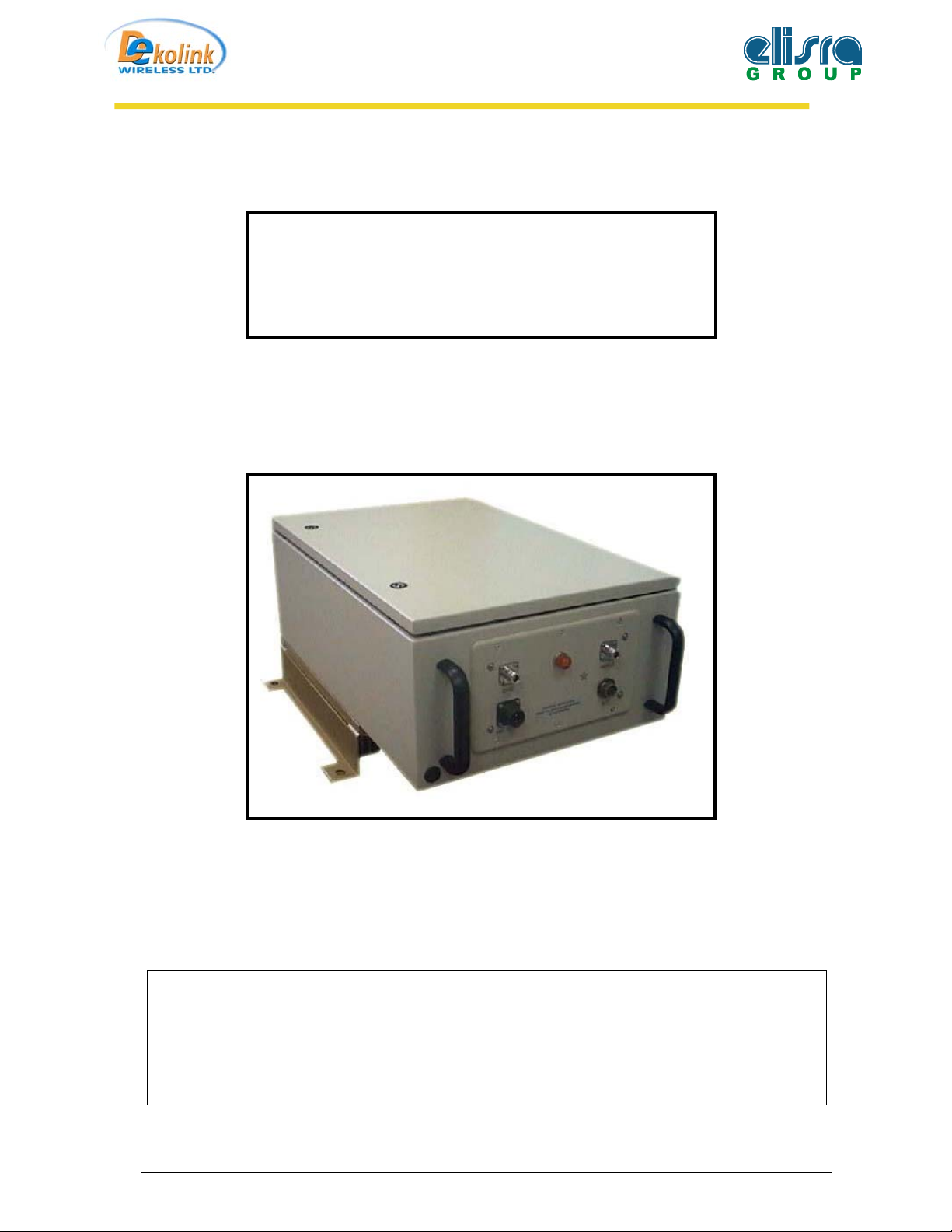
IDEN Digital Repeater Installation
Manual
IDEN Digital Repeater Installation Manual
MW-DR-800-50W90B
DekoLink WireLess
Copying, Distribution, and Disclosure are Prohibited without Express Authorization from
Proprietary and Confidential Information.
DekoLink WireLess Company.
Page 1 of 21
Page 2

IDEN Digital Repeater Installation
1 Table of Contents
Manual
1
2
3
4
5
6
7
8
9
Table of Contents 2
Table Of Figures. 3
Introduction. 4
3.1 Computer Program. ................................................................................................. 4
3.2 Programmable Modules ..........................................................................................4
Electrical Specifications 5
RF Block Diagram 7
System Components description. 8
Repeater Monitor And Control 10
7.1 REPEATER MONITOR AND CONTROL SET-UP...........................................10
Installation of the Repeater in Lab. 11
REPEATER (BDA) OPERATION 12
9.1 AGC (ALC) FUNCTION...................................................................................... 12
9.2 RF GAIN SETTING .............................................................................................12
10 BDA INSTALLTION 13
10.1 BASE / DONOR ANTENNA INSTALLTION....................................................13
10.2 REMOTE / MOBILE ANTENNA INSTALLTION.............................................13
10.3 ANTENNA ISOLATION ..................................................................................... 14
11 INSTALLATION STEPS 15
12 RF EXPOSURE WARNING 16
13 BDA MONITORING AND ALARMS 17
13.1 LINK ALARMS (up link & down link)................................................................ 17
13.2 GENERAL ALARMS........................................................................................... 17
13.3 Measurements........................................................................................................17
14 Repeater Mechanical Outline. 18
14.1 Repeater Case. ....................................................................................................... 18
14.2 Repeater Cover. ..................................................................................................... 19
15 External Alarm Cable. 20
16 Dekolink Wireless Limited Warranty. 21
Page 2 of 21
Page 3

IDEN Digital Repeater Installation
Manual
2 Table Of Figures.
Figure 1: Digital Repeater RF Block Diagram............................................................................... 7
Figure 2: Digital Repeater Layout.................................................................................................. 8
Figure 3: Remote Alarm and Control unit – zoom-out ................................................................. 10
Figure 4: Local Mode Figure 5: Remote Mode ...................................................................... 10
Figure 6: Repeater Downlink rout RF performance test set up. ................................................... 11
Figure 7: Repeater Uplink rout RF performance test set up......................................................... 11
Figure 8: Digital Repeater Mechanical Outline - Case................................................................ 18
Figure 9: Digital Repeater Mechanical Outline - Cover .............................................................. 19
Figure 10: External Alarm Connector .......................................................................................... 20
Page 3 of 21
Page 4

IDEN Digital Repeater Installation
Manual
3 Introduction.
Dekolink Wireless channel selective repeaters employ digital processing techniques to
attain versatile programmable filter array.
The input RF signal is sampled and converted to digital signals. The digital signal is
filtered using fast parallel logic. Using digital processing techniques the system
generates up to 8 (12 optional) separate, programmable and independent filters. The
filter parameters can be easily modified and tailored to meet specific customer
requirements.
3.1 Computer Program.
Repeater Management Software (RMA) supplied with the repeater and provide full access to
all control setting and monitoring capabilities. The RMA software can be installed on
Windows 95, Windows 98, Windows 2000 & Windows XP operation systems.
Dekolink's Repeater Management Application software (RMA) is used to manage and
control the repeater by local connection via RS232 or remotely by Modem.
3.2 Programmable Modules
All Repeater settings made trough Controller unit (CB-04), This unit controls the active
components in the repeater, and communicate with two DDF (Dekolink Digital Filter) units
Up& Downlink trough RS232 Communication.
The controller controls RF Gain, Power On/Off, AGC On/Off & provides Alarms Report .
The controller also set DDF parameters to each DDF units (Uplink & downlink) it sets
Center Frequency, Bandwidth & Enable/Disable each one of the 8 channels separately of the
Uplink/ Downlink path. It allows independence shaping of several filters, by controlling
frequency, frequency bandwidth and type.
Page 4 of 21
Page 5

IDEN Digital Repeater Installation
Manual
4 Electrical Specifications
Frequency Range Downlink 851-866 MHz Uplink 806-821 MHz
Pass band Gain @Min attenuation. Up to 100 dB
Channel Bandwidth See Sample from Table
Channel Setting Resolution 0.5 kHz
Passband Ripple ± 2.5 dB max
Channel Ripple ± 0.5 dB max
Delay Ripple ± 250 nSec max
Noise Figure @max gain 5.0 dB max
3rd Order Output Intercept Point +62 dBm typical +50 dBm typical
IMD @ 4 tone
48 dBc typical
@ 2.5 Watt/tone
45 dBc typical
IMD @ 8 tone
@ 1.25 Watt/tone
Power Output @1 dB Gain Compression 50 Watt 10 Watt
Composite Output Power +40dBm +30 dBm
Automatic Gain Control (user enable) 15 dB attenuation Range
Impedance Level 50 ohms
V.S.W.R In/Out 1.5: 1 max
Spurious Outputs -13dBm max
Power Supply 90 to 260 VAC
Digital Gain Control 0-31dB@1dB/step
Size 400X600X300 cm (15.7x23.6x12 inch)
48 dBc typical
@ 0.25 Watt/tone
45 dBc typical
@ 0.125 Watt/tone
RF Connectors N-type Female
Weight 40 kg. (90 lb) Approx.
Operating temperature
Controller Backup Battery 2 Hours Appox.
Page 5 of 21
- 30°C to + 50°C
Page 6
Examples for filters capability:
IDEN Digital Repeater Installation
Manual
Filter Description
Single Channel @3Channel Spacing 25[KHz] 50[dB] @ Fc±87.5 KHz 25
Single Channel @2Channel Spacing* 25[KHz] 50[dB] @ Fc±62.5 KHz 32
Single Channel @1Channel Spacing 25[KHz] 50[dB] @ Fc±37.5 KHz 50
4 Channel @4 Channel Spacing* 100[KHz] 50[dB] @ Fc±150 KHz 22
4 Channel @2 Channel Spacing* 100[KHz] 50[dB] @ Fc±100 KHz 31
4 Channel @1 Channel Spacing 100[KHz] 50[dB] @ Fc±75 KHz 46
*These filters are installed in the demonstration unit.
Additional filters can be added based on specific customer requirements.
0.5 [dB]
Min Rejection
Bandwidth (min)
Delay [uSec]
(max)
Page 6 of 21
Page 7
IDEN Digital Repeater Installation
5 RF Block Diagram
Manual
BASE
ANT
Downlink
Duplexer
Power
Monitor
MOBILE
Digital Filters
AGC
LNA
Down-
Converter
AGC
Channeler
AGC
PA
AGC
LNA
Up-
Converter
Micro
controller
Digital Filters
Controller
Up-
Converter
Down-
Converter
Interface
Box
AGC
AMP
AGC
AGC
AGC
AMP
PA
Duplexer
Power
Supply
Power
Monitor
Uplink
ANT
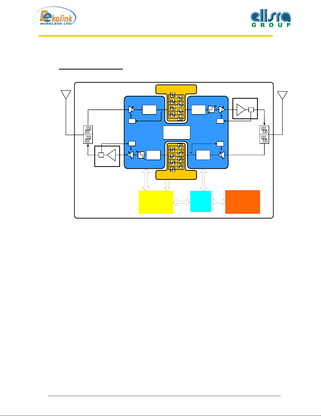
Figure 1: Digital Repeater RF Block Diagram.
Dekolink Wireless channel selective repeaters employ digital processing techniques to attain
versatile programmable filter arrays in both the uplink & downlink paths.
The RF signal entering the repeater, is filtered by a duplexer, amplified, down converted &
sampled to digital signals. The digital signal is filtered using fast parallel logic.
Using digital processing techniques, the system generates up to 8 separate, programmable
and independent filters.
After filtration is accomplished, the digital signals are up-converted to an RF signal,
amplified by a High Power Amplifier & combined by a duplexer to the output port.
Page 7 of 21
Page 8

IDEN Digital Repeater Installation
Manual
6 System Components description.
8
4
14
3
6
1
7
5
15
9
11
10
12
13
2
Figure 2: Digital Repeater Layout.
Page 8 of 21
Page 9

Component Description:
1. Digital Filter Module for Downlink (include operation indication LED )
2. Digital Filter Module for Uplink (include operation indication LED )
3. Channler ( Dual Up/down Converter for Uplink & Downlink Paths).
4. Diplexer to donor Antenna.
5. Diplexer to mobile Antenna (High Power).
6. Coupler for Modem Antenna.
7. Isolator for Uplink Amplifier.
8. Connections Box (include Repeater ON/Off switch).
9. BDA Monitor unit. (include alarm test button)
IDEN Digital Repeater Installation
Manual
10. Controller Unit. (include operation status indication LED).
11. iDEN Modem Unit.
12. Door plate.
13. Door Alarm Switch.
14. Power Supply.
15. Controller Backup Battery.
Page 9 of 21
Page 10
IDEN Digital Repeater Installation
Manual
7 Repeater Monitor And Control
The BDA Monitor Box monitors the DC functioning of the BDA. These faults are sent to the
Control Box. The Control Box detects these faults and controls the BDA functions. These
functions can be monitored or controlled by an external PC through the serial interface connector
on the Control Box.
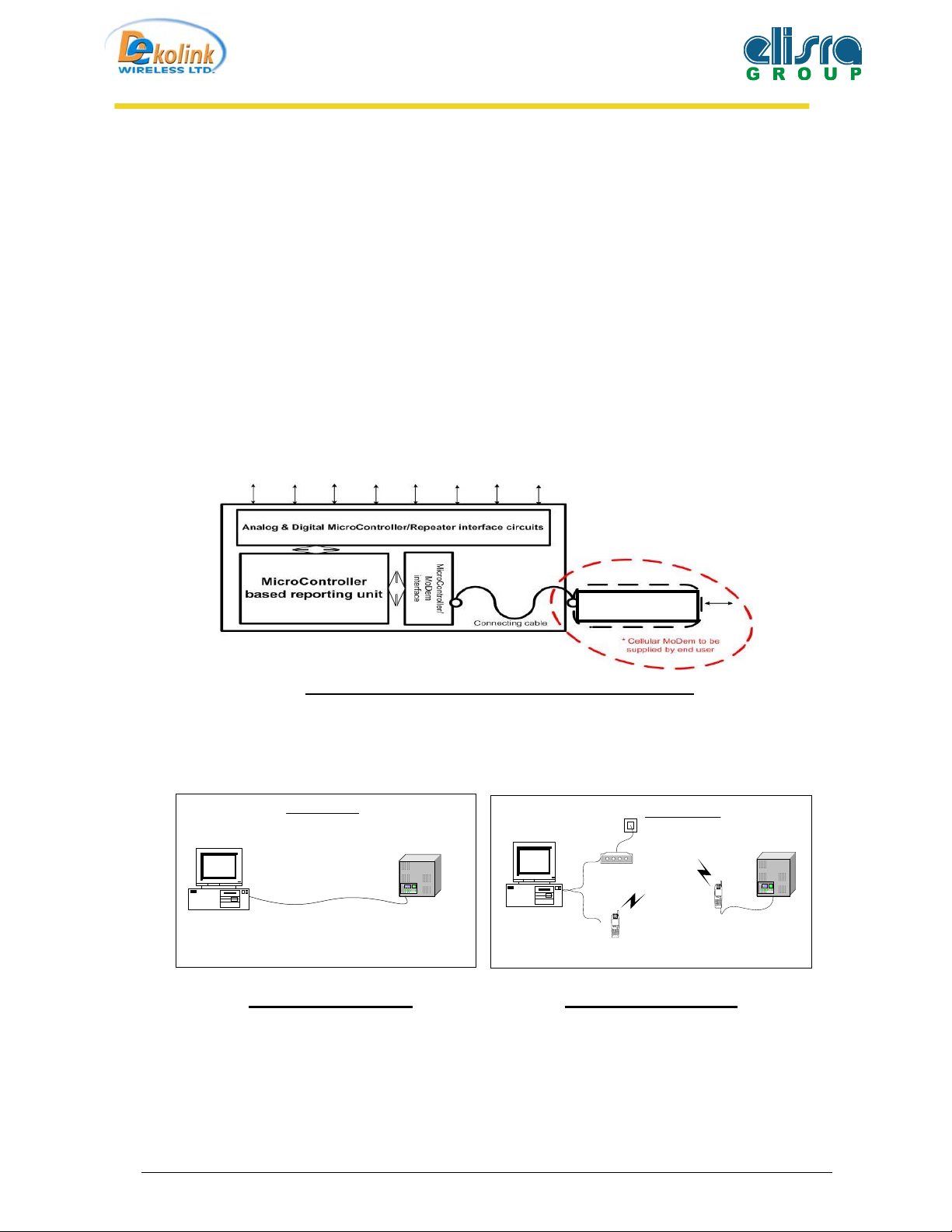
A cellular modem is installed in the BDA. This modem interfaces with the control box and a
remote PC.
Figure 3: Remote Alarm and Control unit – zoom-out
7.1 REPEATER MONITOR AND CONTROL SET-UP
Local Mode
PC / Laptop
BDA Repeater
COM1
PC / Laptop
COM1
Cell Modem
Modem
OR
LG-510
Remote Mode
Cell Modem
LG-510
BDA Repeater
Figure 4: Local Mode
Figure 5: Remote Mode
Page 10 of 21
Page 11

IDEN Digital Repeater Installation
Manual
8 Installation of the Repeater in Lab.
NOTE! In case that Antennas are not connected, terminate the Base & Mobile marked
connectors with a 30dB attenuator, in order to prevent damage (by a regressing signal) to
protect the Test equipment.
The attenuators power rating should be at least 50W at the Mobile marked repeater’s
terminal, and 10W at Base marked repeater’s terminal.
- Connect power supply. A supplied voltage in the range of 90 to 260VAC should be
connected to the repeater’s AC power connector.
- Inject to the repeater’s Downlink route terminal (Base connector), RF Signal from the
connected RF Generator, and a Spectrum Analyzer, to the repeater’s Mobile terminal,
and test the repeater RF performance (see test set up diagram below).
Signal
Generator
Dekolink
Repeater
RF
OUT
RF Cable
30dB
PED
Base Mobile
30dB
PED
RF Cable
Figure 6: Repeater Downlink rout RF performance test set up.
S.Analyzer
RF IN
- Test the Repeaters’ Uplink route, by connecting RF Signal Generator to the repeater’s Mobile
marked terminal and a Spectrum Analyzer to the Base marked terminal (see test set up diagram
below).
S.Analyzer
RF IN
Dekolink
Repeater
RF Cable
30dB
PED
Base Mobile
30dB
PED
RF Cable
Figure 7: Repeater Uplink rout RF performance test set up
Page 11 of 21
Signal
Generator
RF
OUT
Page 12

IDEN Digital Repeater Installation
Manual
9
REPEATER (BDA) OPERATION
The RF connection is made via two type “N” female connectors. The RF connector labeled
“Base” must be connected to the antenna pointing to the base station; usually a rooftop antenna.
The RF connection labeled “Mobile” must be connected to the antenna pointing into the area to
be covered by the Repeater such as inside a building or outdoor shaded area.
The repeater operates from 110V/220 VAC @ 2A.
9.1 AGC (ALC) FUNCTION
The repeater has AGC (Automatic Gain or Level Control) function on both paths that serve to
prevent the saturation of the power amplifier. The amplifier has a directional coupler and a
detector at the output of the high power amplifier to monitor the output power. When a high
signal is received the automatic level control detects the amplitude and sends a feedback signal to
a voltage variable attenuator that attenuates the signal level so that the output power of the
amplifier does not exceed the preset limit. This level control ensures the power amplifier
operation in the linear region only.
9.2 RF GAIN SETTING
For proper operation of the Repeater, the isolation between the base station antenna and the
mobile antenna should exceed the Repeater gain by at least 10 dB. If the Repeater gain is higher
than the isolation between the antennas, oscillation will build up and will saturate the amplifier.
The step attenuator on the low noise amplifier can reduce the Repeater gain. The repeater gain
can be reduced by 31 dB in 1 dB steps.
Page 12 of 21
Page 13

IDEN Digital Repeater Installation
Manual
10 BDA INSTALLTION
Install the BDA Repeater in a shielded, ventilated and easy to reach area.
Use low loss cables to connect antennas to the BDA. Install the BDA close to the service area to
improve output power and noise figure.
The BDA Base/Donor connector port is connected to donor antenna, usually a Yagi antenna,
while the BDA Mobile/Remote connector port is connected to a mobile antenna; outdoor indoor.
10.1 BASE / DONOR ANTENNA INSTALLTION
Typically this is a directional antenna such as Yagi or Dish antenna of 10 to 15 dB gain. This
antenna is pointed to the base station to get maximum input power. This antenna should be in
line of sight with the base site. Raise this antenna higher if no line of site is achieved. The
required Base signals should be the dominant signals; at least 6 dB higher power than other
signals.
Choose the antenna site to get the maximum isolation from the remote (mobile serving) antenna.
10.2 REMOTE / MOBILE ANTENNA INSTALLTION
The second antenna is connected via cable that has typical 1~10 dB attenuation (depends on the
length of the cable) to the CBDA MOBILE port. This type of antenna is omni directional
(isotropic), or wide beam, with 0 to 2 dBi typical gain and is installed and distributes indoor (in
buildings, tunnels, basements, park lots, shopping centers etc.). Typical specifications: gain: 2
dBi, VSWR: better than 2:1, Impedance: 50 ohm. For direct connection to the BDA this antenna
must be installed to provide a minimum separation distance of 2 m (200 cm) from persons
within the area.
Less separation is needed if the power from this power is divided into many antennas covering
many floors or areas.
Page 13 of 21
Page 14

IDEN Digital Repeater Installation
Manual
10.3 ANTENNA ISOLATION
For proper operation the isolation between these two antennas must be at least 10 dB higher than
the BDA gain. Lower isolation would lead to high in-band ripple.
Oscillations will build up when the isolation is lower than BDA gain.
The isolation between the antennas is critical for high gain outdoor repeaters.
To measure the isolation, inject a known signal into one antenna and measure the coupled output
at the other antenna. This should be done across the frequency range of both uplink and downlink
bands.
Page 14 of 21
Page 15

IDEN Digital Repeater Installation
Manual
11 INSTALLATION STEPS
1. Install all antennas and connect them to the BDA inputs.
2. Set “MAX Gain” according to isolation (at least 15 dB lower) and available donor power.
This allows the SAGC to smartly limit the output power of the BDA.
Optional: The SAGC on the Downlink path guarantees constant downlink power (relative to
cell traffic) when and if the Donor power changes.
3. Uplink will set ultimately according to the downlink gain.
4. Check that the uplink FWD power, if power is at constant maximum then isolation between
antennas is low (BDA oscillations) or the BDA is faulty. In such a case:
• Disconnect one of the cables from the BDA connectors and connect a load at the connectors.
FWD power is at constant maximum
If the
•
needs replacing.
FWD power isn’t at constant maximum
If
•
antennas is low. Either improve the isolation (e.g. increase separation) or reduce BDA gain.
• To reduce gain, reconnect the antenna cables. Reduce the
constant maximum
. Reduce the gain further by 10 dB.
then the BDA is faulty (oscillating) and
then the isolation between the donor and remote
“MAX Gain FWD power isn’t at
Page 15 of 21
Page 16

IDEN Digital Repeater Installation
Manual
12 RF EXPOSURE WARNING
In order to satisfy the FCC RF exposure requirements, you must ensure that the installation
complies with the following:
One antenna is connected via cable that has typical 1~10 dB attenuation (depends on the length
of the cable) to the BDA base port. This antenna is installed outdoor and has very sharp beam
(Yagi type or similar) pointed to the donor (BTS). This type of antenna has about 10dBi gain.
Typical specifications: gain: 8 dBd (=10.1 dBi), VSWR: better than 1.5:1, Impedance: 50 ohm.
The outdoor antenna must be installed to provide a minimum separation distance of 1 m (100
cm) from persons within the area.
The second antenna is connected via cable that has typical 1~10 dB attenuation (depends on the
length of the cable) to the BDA MOBILE port. This type of antenna is omnidirecttional
(isotropic), or wide beam, with 0 to 2 dBi typical gain and is installed and distributes indoor (in
buildings, tunnels, basements, park lots, shopping centers etc.). Typical specifications: gain: 2
dBi, VSWR: better than 2:1, Impedance: 50 ohm. For direct connection to the BDA this antenna
must be installed to provide a minimum separation distance of 2 m (200 cm) from persons within
the area.
Less separation is needed if the power from this power is divided into many antennas covering
many floors or areas.
Page 16 of 21
Page 17

IDEN Digital Repeater Installation
Manual
13 BDA MONITORING AND ALARMS
The BDA monitors its functions and alarms are declared when necessary.
Some of these alarms illuminate a red LED on the BDA monitor box.
13.1 LINK ALARMS (up link & down link)
13.1.1 Power Amplifier
Uplink Forward power amplifier Current Alarm: Declared when the Power Amplifier
current is above or below its specified limits.
Downlink Threshold forward output power alarm: Declared when the Power Amplifier
output is lower the specified limits.
13.1.2 Channeler
Declared when the Channeler current is above or below its specified limits.
13.1.3 Channeler lock-detect
Declared when the Channeler synthesizers are unlocked.
13.1.4 DDF Current.
Declared when the DDF current (include Internal FAN) is above or below its specified
limits.
13.1.5 DDF Communication.
Declared when Repeater Controller failed to communicate with The DDF unit.
13.1.6 VSWR >3:1.
This unit is include VSWR >3:1, Declared when the return loss of the downlink
antenna or cable connection exceeds 6 dB (=VSWR 3:1).
13.2 GENERAL ALARMS
13.2.1
13.2.2
Temperature
Main Voltage
Declared When the chassis temperature exceeds 60 C.
Declared when the Power Supply voltage is below or above its limits.
13.3 Measurements.
13.3.1 Temperature Measurements
13.3.2 Downlink Forward Power Measurements.
Page 17 of 21
Page 18

IDEN Digital Repeater Installation
Manual
14 Repeater Mechanical Outline.
14.1 Repeater Case.
Figure 8: Digital Repeater Mechanical Outline - Case
Page 18 of 21
Page 19

14.2 Repeater Cover.
Battery
Connection
Box
IDEN Digital Repeater Installation
Manual
+
Modem Power
NC
Dig Filter Down
Channler
+9v
-
Monitor
Dig Filter Up
Up PAmp
+28v
NC
Modem
Optional
CB-04
Power
Battery
Figure 9: Digital Repeater Mechanical Outline - Cover
RS232
Page 19 of 21
Page 20

IDEN Digital Repeater Installation
15 External Alarm Cable.
Manual
Pinout Definition:
External Swith No.2
A
Ground
B
Not Connected
C
Alarm Out from Monitor Unit (Also
D
shorten to DC connector pin D)
Alarm In from Monitor Unit (Also
E
shorten to DC connector pin B)
Ground
F
External Swith No.1
G
Ground
H
Green/White
Black
Black/White
Black/White
Black
Gray
Black
Figure 10: External Alarm Connector
-
Use Gray & Black Wires for External Alarm 1.
Alarm Connector on Cable
EXT. Switch 2
Alarm In (from Monitor_2)
Alarm Out (from Monitor_15)
H
G
F
E
A
B
C
D
EXT. Switch 2
(Open/Close according to the connected device).
- Use Green/White & Black Wires for External Alarm 2.
(Open/Close according to the connected device).
Page 20 of 21
Page 21

IDEN Digital Repeater Installation
Manual
16 Dekolink Wireless Limited Warranty.
Dekolink Wireless [Ltd.] (“Dekolink”), manufacturer of this product (the “Product”) warrants to the
original purchaser (“Purchaser”) that the Product is free from defects in materials and
workmanship for a term that ends on the earlier of twelve (12) months from the date of activation
of the Product or fifteen (15) months from the date of shipment of the Product by Dekolink. The
obligations of Dekolink under this warranty shall be limited solely to the repair or exchange or
giving credit for, at the option of Dekolink, any Product that may prove defective in accordance
with evidence satisfactory to Dekolink. Any repair or replacement of the Product by Dekolink
shall not extend the original warranty period. This warranty is exclusive to the original
Purchaser and is not assignable.
This warranty applies only upon the condition that the Product has been installed, maintained
and operated under conditions of normal use. The provisions of this warranty shall not apply if,
in Dekolink’s judgment, the Product has been subject to misuse or neglect, damaged in an
accident or by act of vandalism, or repaired or altered in any way that adversely affects its
performance or reliability.
To obtain warranty service, Purchaser may, upon the prior written authorization of Dekolink or its
authorized service representative, return the defective Product to Dekolink’s authorized service
center. All shipping and insurance charges are the sole responsibility of Purchaser and are not
included in this warranty.
Dekolink expressly excludes and disclaims all other warranties, including but not limited to any
warranties of merchantability or fitness for a particular purpose.
Dekolink shall in no event be liable for any special, indirect, incidental, consequential or punitive
damages or for loss, damage, or expense, including loss of use, profits, revenue, or goodwill,
directly or indirectly arising from purchaser’s use or inability to use the merchandise, or for loss
or destruction of other property or from any other cause, even if Dekolink has been advised of
the possibility of such damage. Some states do not allow the exclusion or limitation of incidental
or consequential damages so these limitations may not apply under certain circumstances.
The liability of Dekolink shall in no event exceed an amount equivalent to the purchase price
paid by the purchaser for the defective product.
This warranty shall not be extended, altered or varied except by a written instrument duly signed
by Dekolink.
Page 21 of 21
 Loading...