


© Dekolink Wireless Ltd.—All Rights Reserved Revision 2.0


ABOUT THIS MANUAL
This Product Manual provides the following information:
A description of the Digital Repeater •
•
A functional description of the Repeater
•
A description of its main modules
•
Procedures for setup, configuration and checking the proper functioning
of the Digital Repeater
•
Maintenance and troubleshooting procedures
TO WHOM IT IS INTENDED:
This Product Manual is intended for experienced technicians and engineers. It is
assumed that the customers installing, operating, and maintaining Dekolink Digital
Repeaters are familiar with the basic functionality of repeaters.

DEKOLINK WIRELESS LTD. PRODUCT MANUAL DIGITAL REPEATER
NOTICE
Confidential - Authorized Customer Use
This document may be used in its complete form only and is solely for the use of
Dekolink Wireless Ltd. employees and authorized Dekolink Wireless Ltd.
channels or customers.
The material herein is proprietary to Dekolink Wireless Ltd. Any unauthorized
reproduction, use or disclosure of any part thereof is strictly prohibited.
All trademarks and registered trademarks are the property of their respective
owners.
DISCLAIMER OF LIABILITY
Contents herein are current as of the date of publication. Dekolink Wireless Ltd.
reserves the right to change the contents without prior notice. The information
furnished by Dekolink Wireless Ltd. in this document is believed to be accurate
and reliable. However, Dekolink Wireless Ltd. assumes no responsibility for its
use. In no event shall Dekolink Wireless Ltd. be liable for any damage resulting
from loss of data, loss of use, or loss of profits and Dekolink Wireless Ltd. further
disclaims any and all liability for indirect, incidental, special, consequential or
other similes damages. This disclaimer of liability applies to all products,
publications and services during and after the warranty period.
EXCLUSIVE REMEDIES
The remedies provided herein are the Buyer’s sole and exclusive remedies.
Dekolink Wireless Ltd. shall not be viable for any direct, incidental, or
consequential damages, whether based on contract, tort, or any legal theory.
International Headquarters
Dekolink Wireless Ltd. – Elisra Group
16 Bazel St., Kiryat-Arieh,
Petah-Tikvah 49001 ISRAEL
Tel.: +972 3 918-0180
Fax: +972 3 918-0190
E-mail: marketing@dekolink.com
Website: www.dekolink.com
© Dekolink Wireless Ltd Publication No.: 302-2004 Rev. 2.0
Page b Proprietary Data Pub. 302-2004 Rev. 2.0

DIGITAL REPEATER PRODUCT MANUAL DEKOLINK WIRELESS LTD.
SAFETY WARNINGS AND ADMONISHMENTS
Throughout this manual, important safety warnings and admonishments are included to
warn of possible hazards to persons or equipment. A safety warning identifies a possible
hazard and then describes what may happen if the hazard is not avoided. The safety
warnings – in the form of Dangers, Warnings and Cautions must be followed at all
times. These warnings are flagged by the use of a warning icon, usually the triangular
alert icon seen below. The exclamation point within the triangular alert icon is intended
to warn the operator or service personnel of operation and maintenance from factors
elating to the product and its operating environment, which could pose a safety hazard.
GENERAL SAFETY WARNINGS CONCERNING USE OF THIS SYSTEM
Always observe standard safety precautions during installation, operation and
maintenance of this product. Only a qualified and authorized personnel should carry out
adjustment, maintenance or repairs to the components of this equipment.
Danger: Electrical Shock
This equipment is usually installed outdoors. Wet conditions increase the
potential for receiving an electric shock when installing or using electrically
powered equipment. To prevent electrical shock when installing or modifying
the system power wiring, disconnect the wiring at the power source before
working with uninsulated wires or terminals.
Caution: RF Exposure
Installation of an antenna must comply with the FCC RF exposure
requirements. Refer to paragraph 4.4.
Pub. 302-2004 Rev. 2.0 Proprietary Data Page c

DEKOLINK WIRELESS LTD. PRODUCT MANUAL DIGITAL REPEATER
G
LOSSARY
The following is a list of abbreviations and terms used throughout this document.
Abbreviation/Term Definition
AGC
ALC
ATR
DAS
DDF
DL
Downlink
Automatic Gain Control
Automatic Level Control
Acceptance Test Report
Distributed Antenna System
Dekolink Digital Filter
Dwnlink
The path covered from the Base Transceiver
Station (BTS) to the subscribers/service area
via the repeater
ESD
iDEN
IP3
MN
NMT
PLL
POTS
RF
RMT
SALC
SIM
SQE
UL
Uplink
Electro-Static Discharge
Integrated Digital Enhanced Network
Intermediate Frequency
IF
Third order Intercept Point
Model Number
Network Management Tool
Phased Locked Loop
Plain Old Telephone System
Radio Frequency
Repeater Management Tool
Smart-ALC (Automatic Level Control)
Subscriber Identification Module
Signal Quality Estimate
Uplink
The path covered from the subscribers/service
area to the Base Transceiver Station (BTS)
via the repeater
VSWR
Voltage Standing Wave Ratio
Page d Proprietary Data Pub. 302-2004 Rev. 2.0

DEKOLINK WIRELESS LTD. PRODUCT MANUAL DIGITAL REPEATER
CONTENTS
1. Introduction ..............................................................................................1
1.1 General........................................................................................................................ 1
1.2 Applications ................................................................................................................. 1
1.3 Features....................................................................................................................... 1
1.4 Models and Frequencies............................................................................................... 2
1.5 Unpacking and Inspection............................................................................................ 2
2. Functional Description...............................................................................4
2.1 General........................................................................................................................ 4
2.2 Functional Description................................................................................................. 4
3. Description ................................................................................................6
3.1 Main Components Location ......................................................................................... 6
3.2 Components General Description................................................................................. 8
3.2.1 Channeler...................................................................................................... 8
3.2.2 Monitor Module............................................................................................. 8
3.2.3 Controller...................................................................................................... 8
3.2.4 Digital Filter Module...................................................................................... 8
3.2.5 Connections Box ........................................................................................... 8
3.2.6 Power Supply................................................................................................ 9
3.2.7 Duplexers...................................................................................................... 9
3.2.8 Power Amplifier ............................................................................................ 9
3.3 Monitor Module and Controller Description.............................................................. 10
3.3.1 Monitor Module........................................................................................... 10
3.3.2 Controller.................................................................................................... 11
3.4 Specifications ............................................................................................................. 12
3.4.1 Electrical Specifications ............................................................................... 12
3.4.2 Electrical Specifications ............................................................................... 12
3.4.3 Mechanical Specifications ............................................................................ 13
3.4.4 Connectors.................................................................................................. 13
3.4.5 Environmental Specifications........................................................................ 13
4. Installation ..............................................................................................14
4.1 Safety Instructions ..................................................................................................... 14
4.2 Mechanical Installation.............................................................................................. 14
4.3 Connections ............................................................................................................... 16
4.3.1 RF Connections........................................................................................... 16
4.3.2 Connections – Power Requirements............................................................... 16
4.4 RF Exposure Warning ............................................................................................... 17
4.4.1 General ....................................................................................................... 17
4.4.2 Donor Antenna requirements ........................................................................ 17
Pub. 302-2004 Rev. 2.0 Proprietary Data Page i

DIGITAL REPEATER PRODUCT MANUAL DEKOLINK WIRELESS LTD.
4.4.3 Mobile Antenna requirements ....................................................................... 17
5. Repeater Management Tool (RMT)..........................................................18
5.1 General...................................................................................................................... 18
5.2 Local Connection ....................................................................................................... 18
5.3 Remote Connection.................................................................................................... 19
6. Operation ................................................................................................20
6.1 General...................................................................................................................... 20
6.1.1 Initial Setup................................................................................................. 20
6.1.2 RMT Software – Setting Procedures .............................................................. 20
6.1.3 Saving the Settings....................................................................................... 21
6.2 Smart-ALC Function ................................................................................................. 22
6.2.1 SALC Description ....................................................................................... 22
6.2.2 ALC Function.............................................................................................. 22
6.2.3 RF Gain Setting ........................................................................................... 22
7. Maintenance And Troubleshooting ..........................................................23
7.1 General...................................................................................................................... 23
7.2 Periodic Maintenance................................................................................................. 23
7.3 Visual Inspection........................................................................................................ 23
7.3.1 Monitor Module........................................................................................... 23
7.3.2 Controller Module....................................................................................... 23
7.3.3 Digital Filters Modules................................................................................. 23
7.4 Alarms ....................................................................................................................... 23
7.5 Troubleshooting......................................................................................................... 24
Appendix A: Mechanical Outline................................................................. 27
Appendix B: Alarms AND LEDS .................................................................31
General Alarms.................................................................................................... 31
Temperature Alarm .............................................................................................. 31
Main Voltage Alarm............................................................................................. 31
Monitor Module Alarms ....................................................................................... 31
Uplink and Downlink Alarms................................................................................ 32
Measurements...................................................................................................... 32
Output Power Alarms........................................................................................... 32
Alarms Summary Table........................................................................................ 33
External Alarms Connector Pinout Definition......................................................... 34
LEDs 35
Appendix C: Installing the Repeater in a Laboratory Setting .......................36
Page ii Proprietary Data Pub. 302-2004 Rev. 2.0

DEKOLINK WIRELESS LTD. PRODUCT MANUAL DIGITAL REPEATER
Appendix D: Modem Installation (Option)...................................................37
General 37
Modem Installation .............................................................................................. 37
Connector Pin-out................................................................................................ 38
Appendix E: Dekolink Wireless Limited Warranty ......................................39
Pub. 302-2004 Rev. 2.0 Proprietary Data Page iii


DEKOLINK WIRELESS LTD. PRODUCT MANUAL DIGITAL REPEATER
1. INTRODUCTION
1.1 GENERAL
Dekolink’s Digital Repeaters are channel selective amplifiers that amplify signals bidirectionally between mobile phones and base stations, in cellular and other wireless
mobile telephone systems. Dekolink’s Digital Repeaters employs advanced Digital
Signal Processing (DSP) technology that provides significant advantages over
conventional repeaters.
The Digital Repeaters can be monitored locally or remotely via Dekolink’s Windowsbased Network Management System - RMT software (Refer to the RMT Software
User's Guide for more information).
1.2 APPLICATIONS
Dekolink’s Digital Repeaters introduce new system capabilities that enable a wide
variety of applications particularly when adjacent channel selectivity and/or very high
spectral purity are required. The repeaters provide a solution to situations in which
flexible, high quality and high resolution filtering methods are necessary.
Dekolink’s Digital Repeaters help solve these area coverage problems:
•
•
•
•
•
•
Repeaters also address special application needs such as traffic balancing.
1.3 FEATURES
Some of the of the Dekolink Digital Repeaters' features are listed below:
•
•
Capacity enhancement for existing coverage, •
Extended coverage for rural and isolated areas
Improved in-building coverage
Frequency shift (FSR), sometimes defined as frequency translation or
conversion repeater application
Hole filler application whenever there is no coverage of a particular spot in
the cell site (due to terrain topography or urban structures that shadow areas)
Cell extension to improve the coverage of an existing cell
Repeater On Wheels (ROW) application whenever temporary capacity
enhancement is requested, as during a major event when large crowds gather
50W Downlink (1dB compression point) output power, i.e., 10W Downlink
composite output power
90 dB RF gain
•
Flexible, software controlled, filter array
•
One to eight programmable filters
•
Independent programmable bandwidth for each filter
(12.5 to 250 KHz)
Pub. 302-2004 Rev. 2.0 Proprietary Data Page 1

DIGITAL REPEATER PRODUCT MANUAL DEKOLINK WIRELESS LTD.
High spectral purity •
• • Local and remote monitor and control (software enabled)
Relatively small dimensions
1.4 MODELS AND FREQUENCIES
Dekolink’s Digital Repeater can be provided in several models, as listed below.
The operating frequency ranges depend on the type and model, as specified in the
following table.
Repeater Type Model Number Downlink
(MHz)
iDEN / SMR / LMR 800 MW-DBDA-SMR-50W85 851-866 806-821
iDEN / SMR 900 MW-DBDA-SMR-50W90-PS9 935-941 896-902
Public-safety MW-DBDA-SMR-50W90-PS8 851-869 806-824
NPSPAC MW-DBDA-SMR-50W90-
NPSPAC
2 Way Paging MW-DBDA-SMR-50W90-2PG 928-941 896-902
866-869 821-824
Uplink
(MHz)
1.5 UNPACKING AND INSPECTION
This section provides information for unpacking, inspection and preparation for
installation.
Examine the shipping container for damage before unpacking the unit. Perform a
visual inspection to reveal any physical damage to the equipment.
Verify that the equipment is complete, as listed below and under a packing slip.
Contact Dekolink Wireless Ltd if any of this equipment is missing.
Your Dekolink Digital Repeater comes with the following equipment:
Digital Repeater •
•
Key (used to lock the repeater case)
•
AC cable [6 ft.]
•
Alarm cable [6 ft.]
•
RS232 cable [6 ft.]
•
RMT Software Installation CD
•
RMT Software User's Guide and Digital Repeater Hardware Manual (CD
and hardcopies)
•
Acceptance Test Report (A.T.R.)
•
Packaging Box
Page 2 Proprietary Data Pub. 302-2004 Rev. 2.0

DEKOLINK WIRELESS LTD. PRODUCT MANUAL DIGITAL REPEATER
Please contact Dekolink if you want to order the following optional
•
equipment:
o AC Cable [30 ft.] – Long cable for AC power
o Alarm Cable [30 ft.] – Long cable for External Alarms Input
o Kit for the iR1200 Modem - Mechanical adaptor for the iR1200
modem installation
Pub. 302-2004 Rev. 2.0 Proprietary Data Page 3

DIGITAL REPEATER PRODUCT MANUAL DEKOLINK WIRELESS LTD.
2. FUNCTIONAL DESCRIPTION
2.1 GENERAL
This repeater is designed to help improve communications signal and coverage by
extending the coverage of a base station. The outdoor Donor (Base) antenna receives
the signal from a base station and conveys it to the Digital Repeater. The Repeater
amplifies the signal.
After amplification, the signal is passed through to the Mobile antennas, either
outdoor or indoor. Conversely, signals from handsets are amplified and retransmitted
by the Repeater to the base station.
2.2 FUNCTIONAL DESCRIPTION
The incoming signal processing in the Digital Repeater is processed similarly for both
the Uplink and Downlink paths.
Figure 1 provides a functional block diagram of the Digital Repeater.
Figure 1: Digital Repeater - Block Diagram
The incoming RF signal from either the Base antenna (from the BTS) or from the
Mobile antenna (from the mobile handset) enters the Repeater and is first filtered by
the Duplexer. The incoming signal is amplified by an Automatic Gain Control (AGC)
amplifier, then down-converted.
The input RF signal is then sampled and converted into a digital signal. This digital
signal is filtered using fast parallel logic. The Repeater generates up to eight
separate, programmable, and independent filters using digital processing techniques.
These programmable filters sort the digital signal.
Page 4 Proprietary Data Pub. 302-2004 Rev. 2.0

DEKOLINK WIRELESS LTD. PRODUCT MANUAL DIGITAL REPEATER
After filtration, the digital signals are converted back into analog signals and
up-converted to RF signals by the Up-Converter.
The output RF signal is then amplified by a High Power Amplifier, and combined by
a duplexer before output.
The output signal is emitted by the antennas, either towards the BTS in case of a
signal from the mobile handset, or to the Outdoor antenna or to the Indoor antennas
array, in accordance with the application.
Pub. 302-2004 Rev. 2.0 Proprietary Data Page 5

DIGITAL REPEATER PRODUCT MANUAL DEKOLINK WIRELESS LTD.
3. DESCRIPTION
3.1 MAIN COMPONENTS LOCATION
Figure 2 provides the location of the main components of the Repeater. A list
identifying these components is provided below.
Figure 2: Digital Repeater - Main Components
Page 6 Proprietary Data Pub. 302-2004 Rev. 2.0

DEKOLINK WIRELESS LTD. PRODUCT MANUAL DIGITAL REPEATER
A list of the Digital Repeater main units, in accordance with Figure 2, is provided
below.
1.
Digital Filter Module for the Uplink path (includes status LED)
2.
Uplink Power Amplifier
3.
Duplexer to Base Antenna (low power)
4.
Coupler for Modem Antenna
5.
Isolator for Uplink Amplifier
6.
Channeler (Dual Up/Down Converter for Uplink and Downlink Paths)
7.
Power Supply
8.
Duplexer to Mobile Antenna (high power)
9.
Connections Box (includes Repeater On/Off switch)
10.
Controller Backup Battery Option
11.
Monitor Module (includes alarm LEDs and a LEDs test pushbutton)
12.
Wireless/wireline iDEN Modem Unit – Location
13.
Controller (Control Box - CB) (includes a status LED)
14.
Door Alarm Switch
15.
Door plate
16.
Digital Filter Module for the Downlink path (includes status LED)
17.
External Power indication
18.
Downlink Power Amplifier
Pub. 302-2004 Rev. 2.0 Proprietary Data Page 7

DIGITAL REPEATER PRODUCT MANUAL DEKOLINK WIRELESS LTD.
3.2 COMPONENTS GENERAL DESCRIPTION
A description of the main components of the Digital Repeater follows.
3.2.1 Channeler
The Channeler Module consists of the dual Radio Frequency (RF) Up/Down
Converter sub-modules for Downlink and Uplink paths.
The Channeler amplifies the input RF signals and converts them into an intermediate
frequency (IF). The IF outputs of the Channeler are routed to the Dekolink Digital
Filter (DDF) modules.
In the DDF, the IF inputs from the Channeler are converted back to their original
frequencies. The Channeler also includes digital controllable attenuators (range 32
dB, in steps of 1 dB) and a pre-amplifier for each path.
3.2.2 Monitor Module
The Monitor Module monitors the Repeater operation and provides a visual warning
whenever it detects a failed module or function. The monitoring is performed by
measuring the current of several elements:
DDF Uplink and Downlink, •
•
Up/Down Converter,
•
Uplink Power Amplifier, and
•
Power Supply.
If a module fails, the appropriate red LED lights up and a report is forwarded to the
Control Box.
For a more detailed description of the module, refer to paragraph 3.3.
3.2.3 Controller
The Controller (also called Control Box) controls and monitors the parameters in all
modules of the Repeater. It provides local or remote connection to a PC (See
Dekolink’s RMT User's Guide for more information.).
For a more detailed description of the module, refer to paragraph 3.3.
3.2.4 Digital Filter Module
Dekolink’s Digital Filter Module uses digital processing techniques to generate up to
eight separate, programmable, and independent filters. These filters are activated in
both the Downlink and the Uplink paths.
The filter parameters can be modified and tailored to meet the customer’s specific
applications requirements.
3.2.5 Connections Box
The Connections Box module interconnects the Repeater Modules. This box includes
the Repeater ON/OFF switch and the power fuses.
Page 8 Proprietary Data Pub. 302-2004 Rev. 2.0

DEKOLINK WIRELESS LTD. PRODUCT MANUAL DIGITAL REPEATER
3.2.6 Power Supply
The Power Supply module allows a wide range of input power from different sources:
90 to 260 VAC, maximum power consumption - 350W.
The output power provided to the Repeater internal modules is:
28 VDC or 9 VDC.
3.2.7 Duplexers
The duplexers isolate the transmit path from the receive path. The pass bandwidth of
the duplexer is the entire width of the Uplink band and the Downlink bands
respectively.
3.2.8 Power Amplifier
The power amplifier is the final stage of both the Downlink and Uplink paths. The
Digital Repeater includes Power Amplifiers with relatively high Third Order
Intercept Point (IP3) figures, thus allowing high output power while preserving high
linearity of the output signals.
Pub. 302-2004 Rev. 2.0 Proprietary Data Page 9

DIGITAL REPEATER PRODUCT MANUAL DEKOLINK WIRELESS LTD.
3.3 MONITOR MODULE AND CONTROLLER DESCRIPTION
3.3.1 Monitor Module
The Monitor Module monitors the Repeater operation. It provides local feedback on
some Repeater main modules operation. It issues a visual warning status through the
LEDs on its top enclosure whenever it detects a failed module or function.
This module monitors the DC power supply by performing DC Current and Voltage
measurements. The monitoring is performed by measuring the current of several
elements:
DDF Uplink and Downlink, •
• • Up/Down Converter,
Uplink Power Amplifier
If a monitored element fails, the appropriate red LED lights up. The Monitor Module
transmits the alarm status to the Control Box Module, which controls the Digital
Repeater functions and detects operating failures.
Note
For a detailed description of the LEDs and the error messages, refer to
Appendix B – Alarms.
Figure 3: Monitor Module – Front Panel
Page 10 Proprietary Data Pub. 302-2004 Rev. 2.0

DEKOLINK WIRELESS LTD. PRODUCT MANUAL DIGITAL REPEATER
3.3.2 Controller
The integrated Controller Module (Control Box) enables to set all the Digital
Repeater parameters. This module controls the active components in the Repeater as
well as monitors key operating functions. It communicates with two Dekolink Digital
Filter (DDF) modules (Uplink and Downlink) via the serial port communication.
This Module controls the following functions:
RF Gain, •
•
Power On/Off,
•
AGC On/Off
•
SALC On/Off
Two modes of monitoring and control are available:
•
External PC - through the serial interface connector in the Control Box.
•
Remote control - via a modem connected to the Control Box serial interface.
A standard or cellular modem can be installed inside the Repeater enclosure,
refer to Appendix D.
The Controller also sets the Dekolink digital filter parameters for each Dekolink
Digital Filter (DDF) modules (Uplink and Downlink). This Module sets the Center
Frequency, Bandwidth, slopes and Enable/Disable for each of the eight filters. It
allows the independent shaping of the filters by selecting the required filter from a
choice list of frequently used, factory provided filters. The Controller communicates
with the two DDF modules (Uplink and Downlink) via its serial communication port.
Note
If additional unlisted filters are required, please contact
your Dekolink representative.
The Repeater’s parameters, including the filter settings, are defined and downloaded
with the Dekolink’s RMT software. For more information, see the RMT User's
Guide.
This Module also provides Alarm Reports to the Digital Repeater’s outside world.
The Controller transmits in two modes: Polling and Burst. When operating in Burst
Alarm mode, the Controller generates a burst alarm and reports the faults to the local
or remote connection. The Controller software handles the alarm reporting and
parameters transmission to the Repeater’s outside world.
Pub. 302-2004 Rev. 2.0 Proprietary Data Page 11

DIGITAL REPEATER PRODUCT MANUAL DEKOLINK WIRELESS LTD.
3.4 SPECIFICATIONS
3.4.1 Electrical Specifications
This paragraph provides the electrical, mechanical and environmental specifications
of the Digital Repeater.
Note
Specifications are subject to change without notice.
3.4.2 Electrical Specifications
Parameters Downlink Uplink
Frequency Range Refer to paragraph 1.4..
Pass band Gain @Min
attenuation
Filters Bandwidth 12.5 –250 KHz
Delay 20-80 µsec.
Channel Ripple ± 0.5 dB max ± 0.5 dB max
Delay Variation ± 300 nSec max ± 300 nSec max
Noise Figure @max gain 6.0 dB 6.0 dB
Gain Control setting (by
RMT software) user
defined
3rd Order Output
Intercept Point
IMD @ 4 tone 48 dBc typical
Power Output @1 dB
Gain Compression
Composite Output
Power
Automatic Gain Control
(user enable)
Impedance Level 50 ohms 50 ohms
V.S.W.R In/Out 1.5: 1 max 1.5: 1 max
Spurious Outputs -13 dBm -20 dBm
Power Supply 90 to 260 VAC, maximum consumig power350W
90 dB typical 90 dB typical
12.5 –250 KHz
(Programmable)
(Programmable)
20-80 µsec. Depends
Depending on filter
Bandwidth and
on filter bandwidth and
required slope.
required slope
30 dB @1 dB/step 30 dB @1 dB/step
+62 dBm typical +50 dBm typical
48 dBc typical
@ 33dbm/tone
@ 23 dbm/tone
50 Watt 10 Watt
+40 dBm +30 dBm
15 dB Attenuation
Range
15 dB Attenuation
Range
Page 12 Proprietary Data Pub. 302-2004 Rev. 2.0

DEKOLINK WIRELESS LTD. PRODUCT MANUAL DIGITAL REPEATER
3.4.3 Mechanical Specifications
The following table provides the mechanical specifications of the Digital Repeater.
Element Value
Size H x W x D 600 x 400 x 300 mm (23.6 x 16 x 12 inch)
Weight Approximately 42 kg. (92.4 lbs.)
3.4.4 Connectors
The Repeater interfaces with a Base antenna port and a Mobile antenna port. It
includes four external connectors in its bottom panel, as described below.
Connector Type
RF Connectors:
N-type, Female
BASE / MOBILE
AC Circular, 3-pin
Alarms Circular, 8-pin
3.4.5 Environmental Specifications
Dekolink’s Digital Repeaters meet the European IP65 and American NEMA4
weatherproof standards. The Repeater is designed to operate properly under the
following environmental conditions.
Condition Value
Operating temperature
Storage temperature
- 30° C to + 50°C
- 50° C to + 80°C
Pub. 302-2004 Rev. 2.0 Proprietary Data Page 13

DIGITAL REPEATER PRODUCT MANUAL DEKOLINK WIRELESS LTD.
4. INSTALLATION
4.1 SAFETY INSTRUCTIONS
Before installing the repeater, review the following safety information:
Follow all local safety regulations when installing the repeaters. •
•
Only qualified personnel are authorized to install and maintain the repeater.
When operating the repeater, it is recommended to keep its cover closed while the
power is on. Some maintenance tasks may require the repeater door to be opened
while the power is on. In such cases, perform the required tasks carefully and
remember to close the repeater cover/door when finished.
•
Ground the repeater with the grounding bolt located on the outside of the
cabinet.
•
Do not use the grounding bolt to connect external devices.
•
Use a suitable mounting surface, such as a rigid wall.
•
Follow Electro-Static Discharge (ESD) precautions.
•
Before closing the repeater cover, make sure no wires are in the way.
•
Install the repeater close to the service area to maintain the output power
and noise figure.
•
Use low loss cables to connect the antennas to the repeater.
•
Install the repeater in a shielded, ventilated, and easy-to-reach area.
4.2 MECHANICAL INSTALLATION
The detailed mechanical instructions for the Digital Repeater are provided in the
following publication:
Dekolink Digital Repeater – Deployment and Installation Manual.
Please refer to this document.
Page 14 Proprietary Data Pub. 302-2004 Rev. 2.0

DEKOLINK WIRELESS LTD. PRODUCT MANUAL DIGITAL REPEATER
Figure 4: Digital Repeater - Dimensions
Pub. 302-2004 Rev. 2.0 Proprietary Data Page 15

DIGITAL REPEATER PRODUCT MANUAL DEKOLINK WIRELESS LTD.
4.3 CONNECTIONS
4.3.1 RF Connections
The connection ports are located in the bottom panel of the Digital Repeater. The RF
connection to the Digital Repeater is made via two N-Type female connectors.
The RF connector labeled “BASE” must be connected to the antenna pointing to the
base station (Donor antenna), which is usually a rooftop antenna, Yagi type or dish..
The RF connection labeled “MOBILE” must be connected to the antenna pointing to
the area covered by the Repeater (Service antenna) such as inside a building or in an
outdoor, RF shaded area.
Note
Do not operate the repeater without terminating the antenna connections with actual
antennas or proper dummy loads.
4.3.2 Connections – Power Requirements
The repeater operates from a power source of 110V/220 VAC. The maximum
consumption power is 350W.
Connect the AC power cable to the AC connector in the Repeater. •
Figure 5: Monitor Module – Bottom Panel
Page 16 Proprietary Data Pub. 302-2004 Rev. 2.0

DEKOLINK WIRELESS LTD. PRODUCT MANUAL DIGITAL REPEATER
4.4 RF EXPOSURE WARNING
4.4.1 General
In order to satisfy the FCC RF exposure requirements, it must be ensured that the
installation complies with the following requirements.
4.4.2 Donor Antenna requirements
The Donor antenna connected to the BASE port in the Repeater is usually installed
outdoor. This antenna has a very sharp beam (Yagi type or similar) pointed to the
BTS This type of antenna has 12-20 dBi gain. Cable and jumper loss is at least 2dB.
The Donor antenna must be installed to provide a minimum separation distance of
1 m from any personnel within the area.
4.4.3 Mobile Antenna requirements
The second antenna is connected to the MOBILE port in the Repeater. This interface
serves either an Outdoor antenna or an Indoor antennas array, in accordance with the
application.
In case of Outdoor application, the antenna type is omnidirectional (isotropic)
with 0 to 2 dBi typical gain, or wide beam with up to 10 dBi gain. This antenna is
installed on a mast to cover a shadowed outdoor area. Cable and jumper loss is at
least 2dB. Installation of this antenna must provide a minimum separation distance of
1 m from any personnel within the area.
In case of Indoor coverage, the output power is split into several, omni directional
antenna with 0 to 2 dBi typical gain, and distributed to different indoor areas (in
building floors, tunnels, basements, parking lots, shopping centers etc.). At least 5
such antennas must be connected to the Repeater with cables and splitters. In this
application, the maximum EIRP from each antenna shall not exceed 3W.
Consequently, the minimum required separation distance from any personnel within
the area is 20 cm. Less separation is needed if the power is divided into more than 5
antennas covering many floors or areas.
Pub. 302-2004 Rev. 2.0 Proprietary Data Page 17

DIGITAL REPEATER PRODUCT MANUAL DEKOLINK WIRELESS LTD.
5. REPEATER MANAGEMENT TOOL (RMT)
5.1 GENERAL
The Repeater Management Tool (RMT) software supplied with the Digital Repeater
provides full access to all control settings and monitoring capabilities. The RMT
software can be installed on Windows 95, Windows 98, Windows 2000, and
Windows XP operating systems.
RMT is used to manage, monitor and control the repeater locally via a serial
connection or remotely through a modem. See the RMT User's Guide for more
information.
The RMT allows either a local or remote connection for control of the Repeater.
5.2 LOCAL CONNECTION
To set up a local connection:
Turn on the Repeater and wait for the power LED on the Control Box in the
•
Digital Repeater to begin flashing rapidly.
• • Connect an external serial cable from an external PC (COM interface) to the
Control Box.
Set the Baud rate to 57,600 bps with the RMT software program. (Refer to
the RMT User's Guide for more information.)
Figure 6: Digital Repeater - Local Monitoring with Laptop
Page 18 Proprietary Data Pub. 302-2004 Rev. 2.0

DEKOLINK WIRELESS LTD. PRODUCT MANUAL DIGITAL REPEATER
5.3 REMOTE CONNECTION
To set up a remote connection:
Note
The remote connection is performed to a PC.
1. Connect a modem to the PC serial COM port
2. Set the Baud rate to 57,600 bps with the RMT software (Refer to
the RMT User's Guide for more information.)
Figure 7: Digital Repeater - Remote Monitoring and Control Connection Diagram
See Appendix D: Modem Installation for further installation procedures.
Pub. 302-2004 Rev. 2.0 Proprietary Data Page 19

DIGITAL REPEATER PRODUCT MANUAL DEKOLINK WIRELESS LTD.
6. OPERATION
6.1 GENERAL
Carry out the following steps to operate the repeater (Refer to the RMT User's Guide
for additional information.)
6.1.1 Initial Setup
Perform the following procedures (if not yet performed):
The following are further described in the Deployment and
Measure the isolation between the antennas •
•
Measure the power of the chosen channels in the donor antenna field (Use
external test equipment for this action.)
•
Install the unit in the field
Note
Installation Manual.
•
Connect the antenna cables to the Repeater's BASE and MOBILE
connectors
•
Connect the AC power cable to the AC connector
Note
After the AC power is connected to the repeater, the Power Supply, and the fans
start operating in the Repeater. Please note that the Repeater does not start
operating until the ON/OFF switch located on the
Connections Box is set to ON).
•
Turn on the Repeater (The ON/OFF switch is located on the Connections
Box).
•
Connect a PC/laptop to the Repeater’s Controller with a serial cable for
local connection (Refer to the RMT User's Guide for details).
•
For Remote connection instructions, please refer to Appendix D.
6.1.2 RMT Software – Setting Procedures
Using the RMT software, perform the following procedures:
•
Mute the downlink and uplink amplifiers so that they do not interfere with
the frequency spectrum.
•
Set the maximum transmitted power for Downlink and Uplink(Max Power)
according to the actual onsite requirements
•
Set the Max Gain according to the measured/calculated input power.
Dekolink recommends setting the Maximum Gain value to approximately
18 dB less than the isolation between the antennas/
If you use SALC, there is no need to measure or calculate the gain in
accordance with the required output power because it is adjusted
automatically to attain the selected power. (For more information, see
section 9.4, Smart-ALC Function).
Page 20 Proprietary Data Pub. 302-2004 Rev. 2.0

DEKOLINK WIRELESS LTD. PRODUCT MANUAL DIGITAL REPEATER
Click the Digital Filters Application button in the Repeater Interface screen •
•
Select Tools / Read Filters in the Menu bar
•
Click Yes in the dialog box. The current digital filter configuration in the
Repeater is displayed
•
Set the filter configuration (number of filters, frequencies and filters type) in
the Downlink page
•
Activate the relevant channels by clicking √ in the On/Off checkbox
•
Select the Uplink tab and set the digital filter configuration accordingly.
After defining the digital filters (Downlink and Uplink), download the new data to the
repeater so that the information can go into effect.
6.1.3 Saving the Settings
Two ways to save the settings into the repeater are available:
•
Download to RAM for temporary setting, and
•
Burn-in to Flash for permanent setting.
To savethe settings:
•
Download to RAM.
Click
This technique is recommended for trials, tests and preliminary setup of the
digital repeater until the final configuration of the digital filters is achieved.
You can download the settings an unlimited number of times using
Download to RAM.
This process is however volatile and the information will be lost in the event
of a power failure. The DDF parameters are kept in a volatile memory only,
and should be burned to a Flash memory at finalization of the process.
•
Click the
Burn-in to Flash button to download the data to a non-volatile
(FLASH) memory.
You can download the data to the Flash memory a relatively large but
limited number of times (several hundreds). It is recommended to burn the
data into the Flash memory only, after you are satisfied with the filter
settings for the required application and intend to use it for long period of
time.
To finalize the procedure:
•
Disable the Mute for the downlink and uplink amplifier and test the
performance in the coverage area. (Mute is the output power on/off control,
which can be set via “P.Amp On” checkbox.)
•
Save the configuration files of the digital filters by selecting
File / Save configuration in the Digital Filter Application and assigning a
appropriate name to the file. This data is not saved in the RMT Database.
Pub. 302-2004 Rev. 2.0 Proprietary Data Page 21

DIGITAL REPEATER PRODUCT MANUAL DEKOLINK WIRELESS LTD.
6.2 SMART-ALC FUNCTION
6.2.1 SALC Description
The Smart Automatic Level Control (Smart-ALC) is an innovative solution for
automatic repeater gain adjustment. Combined with advanced control algorithms,
SALC can perform gradual learning of traffic load characteristics and adjust the
Repeater Gain to the desired value.
This automatic operation practically removes the need to make initial settings for
maximal traffic load conditions and eliminates the need for numerous site visits to
take care of Gain adjustment.
SALC also reduces isolation problems and Sync amplification, and maintains
Uplink/Downlink balance.
6.2.2 ALC Function
The Repeater includes the Automatic Level Control (ALC) function on both the
Uplink and Downlink power amplifiers to prevent the saturation of the amplifier.
The amplifier includes a directional coupler and a detector that monitor the output
power. The ALC mechanism samples the output power, and decouples and rectifies
it. The ALC mechanism sends a feedback signal to a voltage variable attenuator
(VVA) that, whenever a high input signal is received, attenuates the signal level so
that the output power of the amplifier does not exceed the preset limit.
This level control ensures that the power amplifier operation stays within the linear
region only, thus preventing saturation and signal distortion.
The ALC protects the amplifiers from overloading and prevents the system from
generating spurious emissions. ALC limits the output power to a constant value
(Maximum output power). The ALC is factory preset to ON state.
6.2.3 RF Gain Setting
The gain range is 59-90 dB. The RF Gain is set separately for Uplink and Downlink.
The gain range should be set via the RMT in accordance with the input signal power
at the Donor antenna, and in accordance with the required Downlink output power.
The gain range is set using the Max Gain function (beware not to exceed isolation
limits, see note below).
The Uplink Gain is set by the Gain Delta field (that is the difference between the
Downlink Gain and the Uplink Gain) in accordance with the system needs. Note that
usually this field is set to “0” for system transparency. Please refer to Installation
Manual.
Note
It is recommended to set the Downlink path gain to a maximum of 18 dB below the
isolation between the Base antenna and the Mobile antenna.
Page 22 Proprietary Data Pub. 302-2004 Rev. 2.0

DEKOLINK WIRELESS LTD. PRODUCT MANUAL DIGITAL REPEATER
7. MAINTENANCE AND TROUBLESHOOTING
7.1 GENERAL
This section provides the maintenance and troubleshooting procedures for the Digital
Repeater.
7.2 PERIODIC MAINTENANCE
There is no periodic maintenance required for the Digital Repeater. As long as it is
installed in a shaded area and not subject to extreme temperatures, it will provide long
term, carefree operation.
7.3 VISUAL INSPECTION
Note
Refer to Appendix b – Alarms and LEDs.
Check the following normal LEDs status inside the repeater:
During normal operation, all LEDs are off. •
• The LEDs should be checked 10 seconds after setting the Repeater on.
Their status should be as described below.
7.3.1 Monitor Module
All LEDs in this module are off.
These LEDs indicate faults in the Repeater and the status of some of them is also
displayed in the RMT main screen.
7.3.2 Controller Module
Ten seconds after turning the Repeater on, the Controller LED starts blinking rapidly.
This is a normal state and indicates that you can now make a connection to the
Controller via its RS232 port, and set the list of filters as defined by the RMT
software.
7.3.3 Digital Filters Modules
The LEDs located on these modules indicate the power status.
7.4 ALARMS
The Repeater issues a series of alarms to warn for malfunctions, as listed in
Appendix B.
Pub. 302-2004 Rev. 2.0 Proprietary Data Page 23

DIGITAL REPEATER PRODUCT MANUAL DEKOLINK WIRELESS LTD.
7.5 TROUBLESHOOTING
The following table summarizes various error/warning alarms and indications, their
possible cause, and a course of action to correct the problem.
Indication Probable Cause Recommended Action
Power Supply
Voltage alarm
Power Amplifier
Uplink Current
alarm
Channeler Current
alarm
Downlink/Uplink
Digital Filter
module’s current
alarm
Supply voltage fault Check if the temperature alarm
is active. If so, see temperature
alarm below.
Turn the power off and on
again (*).
Power Amplifier
Fault
Mute the Uplink Power
amplifier. Turn it back on (*).
Channeler failed Check if a temperature alarm is
active. If so, see the
Temperature alarm below.
Check if the Lock Detect alarm
is active. If so, see the Lock
Detect alarm below.
Decrease the gain of the
Repeater to minimum, check
the alarm, and turn it back to
Maximum Gain (*).
High/Low current
fault in the
Downlink/Uplink
Digital Filter modules
and in the fan
Reset the Digital Filter by
pressing the Reset button.
Change the number of
channels that are active to
minimum and then turn it back
to maximum (*).
Downlink/Uplink
Communication
alarm
The communication
between the
Controller and
Reset the Digital Filter unit by
pressing the Reset button.
Reboot the repeater (*).
Downlink/ Uplink
Digital Filter failed
Downlink/Uplink
Lock Detect alarm
FWD Power
Amplifier alarm
(this is not a fault)
Faulty status of the
Phased Locked Loop
(PLL) in the
Channeler unit
Composite output
power is below the
threshold value
Reboot the Repeater.
Check the connection between
the Controller and the
Channeler (*).
Check the Donor antenna
connection.
Check that the Donor antenna
alignment is in line of sight
with the Base station.
Page 24 Proprietary Data Pub. 302-2004 Rev. 2.0

DEKOLINK WIRELESS LTD. PRODUCT MANUAL DIGITAL REPEATER
Indication Probable Cause Recommended Action
Increase the RF Gain.
Verify the filters’ frequency
setting.
Downlink Return
Power [VSWR]
alarm
High Voltage
Standing Wave Ratio
(VSWR) at the
Mobile port
Temperature alarm Indicates an inner
temperature over
60ºC. The power
supply shutdowns the
Repeater when the
temperature reaches
70ºC
Door Open alarm Indicates that the
Repeater door is open
Excessive intermodulation or
spurious
Amplifier oscillation
caused by insufficient
isolation
frequencies alarm
(External test
equipment)
Check the antenna and cable
connection at the Mobile port.
Replace the antenna if
necessary.
Verify that the repeater is
mounted correctly, with the
Repeater gland plate facing the
floor.
Increase ventilation.
Close the Repeater door.
Check the connection of the
door switch.
Improve the isolation between
the antennas or reduce the RF
gain.
Use the Smart ALC feature.
Excessive noise in
Downlink /Uplink
Connection to the
Controller failed in
the local connection
High input power
causing amplifier
overload
Communication
failure
Use the Smart-ALC feature
Reduce the Max Gain in the
Downlink path
Check the input power to the
repeater - should be less than
20 dBm
Check the Channeler LEDs. If
active (red), this indicates that
the input power to the repeater
is high
If the signal in the donor side is
too high, connect an external
10dB attenuator in series to the
Base connector and increase
the gain by 10dB.
Check the physical connection
between the PC COM1 and the
Controller RS232 interface.
Verify that the LED of the
controller is blinking rapidly.
Pub. 302-2004 Rev. 2.0 Proprietary Data Page 25

DIGITAL REPEATER PRODUCT MANUAL DEKOLINK WIRELESS LTD.
Indication Probable Cause Recommended Action
Reboot the Repeater.
Restart the PC.
Re-install the Controller
software *
Connection with
the Repeater failed
in the remote
connection
Communication
failure
Check that the modem is
physically connected to the
controller serial input.
Verify that the modem local
port baud rate is 57,600 bps.
Verify that the Controller LED
is blinking.
Verify that the modem is
connected to the antenna cable
via the RF coupler.
Restart the PC.
Reinstall the Controller
software.
(*) If the indication remains after the On/Off procedure, replace the Repeater.
Page 26 Proprietary Data Pub. 302-2004 Rev. 2.0

DEKOLINK WIRELESS LTD. PRODUCT MANUAL DIGITAL REPEATER
APPENDIX A: MECHANICAL OUTLINE
This appendix contains the mechanical outline of the Repeater.
Digital Repeater - Mechanical Outline
Figure 8: Digital Repeater – Mechanical Outline
Pub. 302-2004 Rev. 2.0 Proprietary Data Page 27
DIGITAL REPEATER PRODUCT MANUAL DEKOLINK WIRELESS LTD.
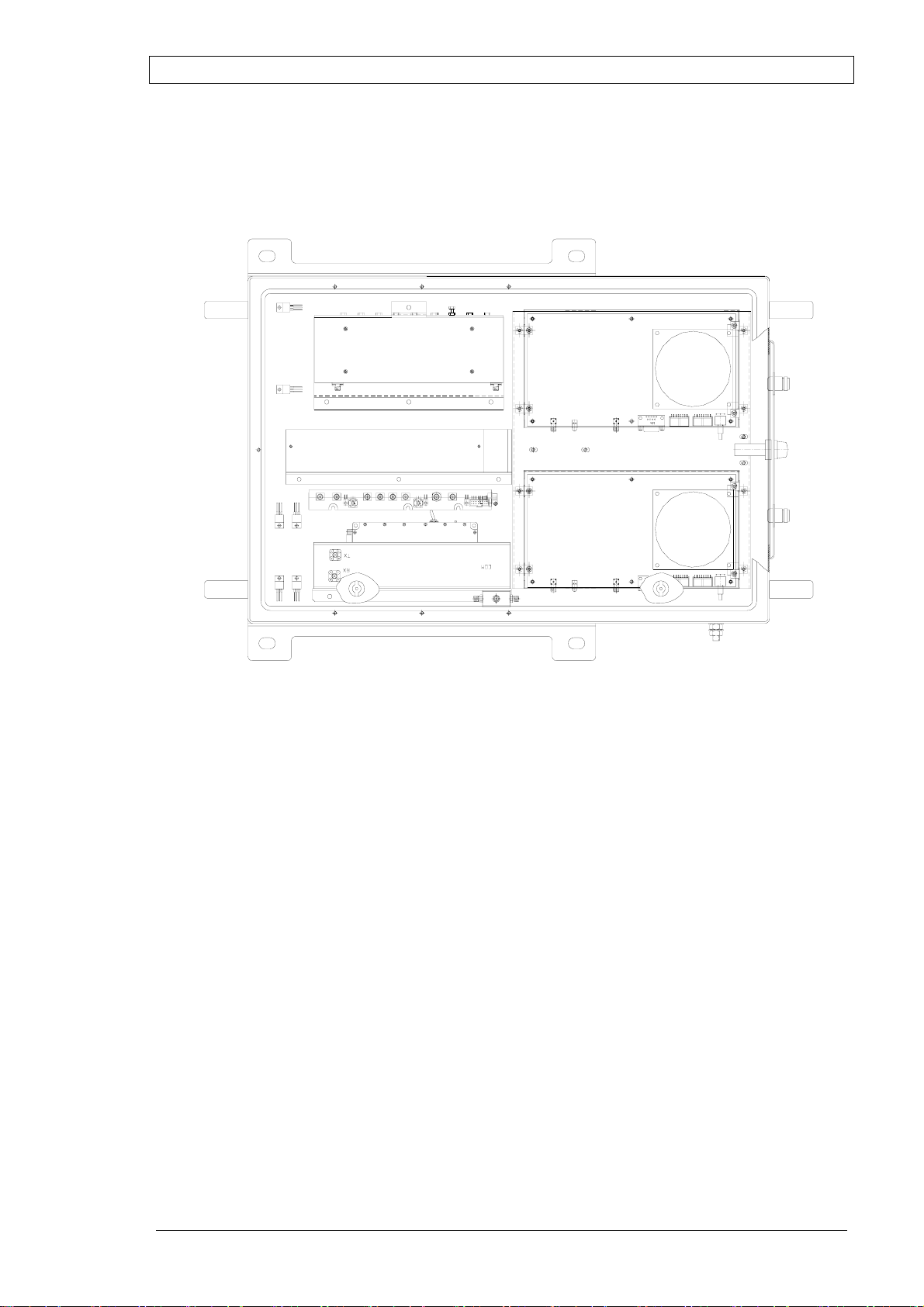
Digital Repeater - Case Outline
The following figure shows the Case layout for Repeater Model Number:
MW-DBDA-SMR-50W85
Figure 9: Digital Repeater – Case Layout
Page 28 Proprietary Data Pub. 302-2004 Rev. 2.0

DEKOLINK WIRELESS LTD. PRODUCT MANUAL DIGITAL REPEATER
The following figure shows the Case layout for Repeater Model Number:
MW-DBDA-SMR-50W90-PS9
Figure 10: Digital Repeater - Case Outline
Pub. 302-2004 Rev. 2.0 Proprietary Data Page 29

DIGITAL REPEATER PRODUCT MANUAL DEKOLINK WIRELESS LTD.
Digital Repeater - Cover Outline
+
Battery
Modem Power
-
Modem
Optional
Monitor
Connection
Box
NC
Dig Filter Down
Channler
+9v
Figure 11: Digital Repeater - Cover Outline
Dig Filter Up
Up PAmp
+28v
NC
CB-04
Power
RS232
Battery
Page 30 Proprietary Data Pub. 302-2004 Rev. 2.0

DEKOLINK WIRELESS LTD. PRODUCT MANUAL DIGITAL REPEATER
APPENDIX B: ALARMS AND LEDS
General Alarms
In case of failure, the repeater triggers an alarm message and transmits its alarm status
to the NMS through a remote or local PC connection In addition, the relevant LED
lights up in the Repeater external front panel.
The major alarms issued by the Digital Repeater are described below. A description
of the LEDs statuses is provided in following paragraphs.
Temperature Alarm
This alarm is triggered when the chassis temperature exceeds 60C° (ambient) within
the Repeater case.
Main Voltage Alarm
This alarm is triggered when the Power Supply voltage is outside its limits. The
operating voltage is 28V.
Monitor Module Alarms
General
The Monitor Module controls, by measuring the current, major functions of the
Repeater, such as:
DDF Uplink and Downlink, •
•
Up/Down Converter,
•
Uplink Power Amplifier, and
•
Power Supply voltage.
Some of these alarms trigger a red LED on the Repeater Monitor Module.
Figure 12: Monitor Module – LEDs Location
Pub. 302-2004 Rev. 2.0 Proprietary Data Page 31

DIGITAL REPEATER PRODUCT MANUAL DEKOLINK WIRELESS LTD.
Uplink and Downlink Alarms
A list of Uplink and Downlink alarms is provided below.
Power Amplifier
Uplink Forward Power Amplifier Current Alarm: This alarm is triggered when
the Power Amplifier current is outside of its specified limits.
Downlink Threshold Forward Output Power Alarm: This alarm is triggered
when the Power Amplifier output is lower than the specified limits.
Channeler
This alarm is triggered when the Channeler current is outside of its specified limits.
Channeler Lock-Detect
This alarm is triggered when the Channeler synthesizers are unlocked.
DDF Current
This alarm is triggered when the DDF current (including the internal fan) is outside of
the specified limits.
Voltage Standing Wave Ratio (VSWR)
This alarm is triggered when the return loss of the Downlink antenna or cable
connection exceeds 6 dB (VSWR 3:1).
The VSWR module measures the voltage standing wave ratio of the Downlink output
antenna port. If the VSWR falls below 13 dB, an alarm is triggered.
This alarm provides an indication of the status of the cable connected to the antenna.
If a cable is defective, the VSWR is decreased and the alarm is triggered again. The
alarm can be forwarded to the RMT so that faults and irregularities can be recognized
and eliminated rapidly.
DDF Communication
DDF communication is triggered when the Repeater Controller fails to communicate
with the DDF unit. The communication with digital repeater components is made via
the Control Box. If the Controller fails to read/update parameters with the Digital
Filter module, it triggers the communication alarms.
Measurements
Temperature Measurements: Measures ambient temperature of the digital repeater
chassis. A temperature sensor is placed on the heat sink and provides analog voltage
to the Control Box. The controller processes the input with a formula and provides
the measured temperature.
Downlink Forward Power Measurements: Measures the output power of the
Downlink (if the output power is less than 30 dBm, 30 dBm is displayed.) This
module measures the composite output power in the downlink output path of the
repeater.
Output Power Alarms
If the output power falls below a certain level, an alarm is triggered. You can set the
power level and the mask for the alarm. (See the RMT User's Guide for more
information.) This feature provides you with the output power of the repeater and
thereby achieves optimum output power.
Page 32 Proprietary Data Pub. 302-2004 Rev. 2.0

DEKOLINK WIRELESS LTD. PRODUCT MANUAL DIGITAL REPEATER
The alarms can be forwarded to the RMT by burst or polling, so that faults can be
recognized and eliminated rapidly.
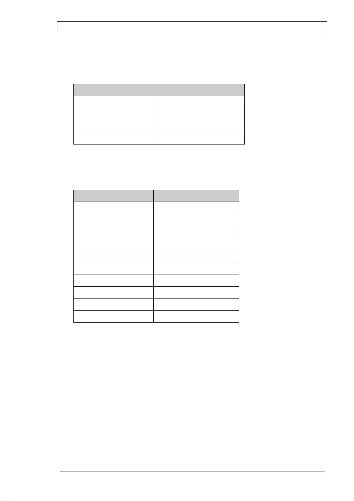
Alarms Summary Table
The following table lists the alarms.
Alarm Alarm Description
Door Open Generates an alarm when the Repeater door
is open.
Temperature Generates an alarm when the ambient
temperature is above 60º C inside the
Repeater enclosure.
Power Supply 9V or 28V
(triggers a LED)
Generates an alarm when the power supply
exceeds the designated limits (±2V).
Fan Failure Generates an alarm when the fan current is
outside of the allowed limits.
External Alarm Generates an alarm when the external input
contacts are open or closed (User Definable).
Lock Detect Alarm Generates an alarm when the Channeler
Reference frequency is not stable.
Channeler Current
(triggers a LED)
Generates an alarm when the Channeler
current is outside of the allowed limits.
Downlink VSWR Alarm Generates an alarm when the Downlink
VSWR is above 1:2.5
Downlink Forward Power
Alarm
Generates an alarm when the Downlink
power is less than the Power Threshold value
(User definable)
Digital Filter Current
Alarm
Generates an alarm when the digital filter
module current is outside of the allowed
limits.
Digital Filter
Communication Alarm
Generates an alarm when communication
with the DDF unit fails.
Pub. 302-2004 Rev. 2.0 Proprietary Data Page 33

DIGITAL REPEATER PRODUCT MANUAL DEKOLINK WIRELESS LTD.
A
A
A
External Alarms Connector Pinout Definition
The following table details the pinout definition of the External Connector located in
the gland plate of the repeater.
Letter Description Color Code
A External Switch No.2 Green/White
B Ground Black
C Not Connected N/A
D N/A N/A
E Alarm Out from Monitor Unit
Black/White
(shortened to the DC connector pin)
F Alarm In from Monitor Unit
Black/White
(shortened to DC connector pin)
G External Switch No.1 Gray
H Ground Black
A External Switch No.2 Green/White
H
EXT. Sw itc h 2
la r m In ( fr om Mon ito r _2 )
larm Out (from Monitor_15)
G
Figure 13: External Alarms Connector – Pinout
F
E
D
B
C
EXT. Sw itc h 2
Notes
1. Use Gray and Black Wires for External Alarm 1 (Open/Close according to the
connected device).
2. Use Green/White and Black Wires for External Alarm 2 (Open/Close according
to the connected device).
Page 34 Proprietary Data Pub. 302-2004 Rev. 2.0

DEKOLINK WIRELESS LTD. PRODUCT MANUAL DIGITAL REPEATER
LEDs
General
If any of the Repeater major functions as listed below fails, the relevant LED lights
up in the Monitor Module panel (see Figure 12):
DDF Uplink and Downlink, •
•
Up/Down Converter,
•
Uplink Power Amplifier, and
•
Power Supply voltage.
In addition to the LEDs, the alarm indication is sent to the Control Box that triggers
an alarm message. This allows receiving the alarm status of the Repeater from the
Monitor Module with a remote or local PC connection.
LEDs Description / Cause of Failure
The following table lists the probable cause of failure in accordance with the LEDs
statuses.
LED Description / Probable Cause of Failure
NC Not in use (not connected)
DL Dig Fil. Downlink digital filter failed
Converter Curr Channeler current failed
+9V Power supply (+9V) failed
NC Not in use (not connected)
UL Dig Fil. Uplink digital filter failed
UP PWR Amp. Uplink power amplifier failed
+28V Power supply (+28V) failed
Pub. 302-2004 Rev. 2.0 Proprietary Data Page 35

DIGITAL REPEATER PRODUCT MANUAL DEKOLINK WIRELESS LTD.
APPENDIX C: INSTALLING THE REPEATER IN A LABORATORY SETTING
If you want to test the performance of the repeater prior to actually installing it in the
field, you can do so in a laboratory setting as follows:
Note
In the event that the antennas are not connected, terminate the Base and Mobile
connectors with a 30 dB attenuator or 50 Ohm load.
This will prevent a regressing
signal from damaging the test equipment.
Use 30db attenuators with a power rating of at least 50W at the Mobile connector
and at least 10W at the Base connector.
Connect a Power Supply voltage (90 to 260 VAC) to the Repeater’s AC
•
connector (refer to the test diagram below).
•
Connect an RF Generator to the Repeater’s Base connector
•
Inject an RF Signal from the connected RF Generator to the downlink route
through the Base connector.
•
Connect a Spectrum Analyzer to the Mobile connector.
•
Test the repeater’s RF performance.
Signal
Generator
RF
OUT
RF Cable
30dB
Attenuator
Dekolink
Repeater
Base Mobile
30dB
Attenuator
RF Cable
S.Analyzer
RF IN
Figure 14: Repeater Downlink Route RF Performance Test Setup
Test the Repeater’s Uplink route by connecting the RF Signal Generator to
•
the Mobile connector
• Connect a Spectrum Analyzer to the Base connector (refer to the test setup
diagram below).
Dekolink
S.Analyzer
RF IN
RF Cable
30dB
Attenuator
Repeater
Base Mobile
30dB
Attenuator
RF Cable
Figure 15: Repeater Uplink Route RF Performance Test Setup
Signal
Generator
RF
OUT
Page 36 Proprietary Data Pub. 302-2004 Rev. 2.0

DEKOLINK WIRELESS LTD. PRODUCT MANUAL DIGITAL REPEATER
APPENDIX D: MODEM INSTALLATION (OPTION)
General
The Digital Repeater is ready for connection of a serial, Hayes Compatible, AT
Command type modem with a phone number to allow connection in a circuit
switched network.
If you are using a modem with a SIM card, special settings (network or terminal
definitions) may be needed to allow data transmission.
Modem Installation
Perform the following steps to install a standard modem:
•
•
Use the following commands:
Connect the modem to the power supply. •
Install the modem with a straight serial cable. This cable is usually supplied
with the modem. (See the tables below for the pinout description.)
Use a PC with the same terminal mode and bit rate as the default modem
baud rate. For example, 57,600, 19,200, 14,400 bps or other baud rate
depending on the modem default configuration.
•
AT S0=0 <ENTER>
•
AT+IPR=57600 <ENTER>
•
Change terminal baud rate to 57,600 bps if necessary.
•
Use the PC in terminal mode to save the new baud rate settings.
Use the following commands:
•
D AT&W1 <ENTER> (For some modems)
•
AT&W0 <ENTER> (For other modems)
•
Disconnect the serial cable from the PC and connect it to the Controller in
the Repeater.
•
Connect the antenna cable to the modem antenna port. (When testing the
unit in a laboratory, connect the modem to an external antenna) Refer to
Appendix C for more information.
•
Connect the modem to a Power Supply unit terminal.
•
Turn the Repeater AC power on.
•
Use a PC with a wireless or Plain Old Telephone System (POTS) modem
and the Dekolink RMT software to monitor the repeater.
•
Refer to the RMT User's Guide for more information on how to establish
remote connection with a repeater.
Pub. 302-2004 Rev. 2.0 Proprietary Data Page 37
DIGITAL REPEATER PRODUCT MANUAL DEKOLINK WIRELESS LTD.
Connector Pin-out
Serial Cable Pin-out for Local Communication between the PC and the Controller:
PC Pinout CB Pinout
2 3
3 2
5 5
D-Type 9 Pin female D-Type 9 Pin female
Serial Cable Pinout for Remote Communication between the Modem and the
Controller:
DCE Modem DTE Controller
1 1
2 2
3 3
4 4
5 5
6 6
7 7
8 8
9 9
D-Type 9 Pin female D-Type 9 Pin male
Page 38 Proprietary Data Pub. 302-2004 Rev. 2.0

DEKOLINK WIRELESS LTD. PRODUCT MANUAL DIGITAL REPEATER
APPENDIX E: DEKOLINK WIRELESS LIMITED WARRANTY
Dekolink Wireless [Ltd.] (“Dekolink”), manufacturer of this product (the “Product”)
warrants to the original purchaser (“Purchaser”) that the Product is free from defects
in materials and workmanship for a term that ends on the earlier of twelve (12)
months from the date of activation of the Product or fifteen (15) months from the date
of shipment of the Product by Dekolink. The obligations of Dekolink under this
warranty shall be limited solely to the repair or exchange or giving credit for, at the
option of Dekolink, any Product that may prove defective in accordance with
evidence satisfactory to Dekolink. Any repair or replacement of the Product by
Dekolink shall not extend the original warranty period. This warranty is exclusive to
the original Purchaser and is not assignable.
This warranty applies only upon the condition that the Product has been installed,
maintained and operated under conditions of normal use. The provisions of this
warranty shall not apply if, in Dekolink’s judgment, the Product has been subject to
misuse or neglect, damaged in an accident or by act of vandalism, or repaired or
altered in any way that adversely affects its performance or reliability.
To obtain warranty service, Purchaser may, upon the prior written authorization of
Dekolink or its authorized service representative, return the defective Product to
Dekolink’s authorized service center. All shipping and insurance charges are the sole
responsibility of Purchaser and are not included in this warranty.
Dekolink expressly excludes and disclaims all other warranties, including but not
limited to any warranties of merchantability or fitness for a particular purpose.
Dekolink shall in no event be liable for any special, indirect, incidental, consequential
or punitive damages or for loss, damage, or expense, including loss of use, profits,
revenue, or goodwill, directly or indirectly arising from purchaser’s use or inability to
use the merchandise, or for loss or destruction of other property or from any other
cause, even if Dekolink has been advised of the possibility of such damage. Some
states do not allow the exclusion or limitation of incidental or consequential damages
so these limitations may not apply under certain circumstances.
The liability of Dekolink shall in no event exceed an amount equivalent to the
purchase price paid by the purchaser for the defective product.
This warranty shall not be extended, altered or varied except by a written instrument
duly signed by Dekolink.
Pub. 302-2004 Rev. 2.0 Proprietary Data Page 39
 Loading...