


© Dekolink Wireless Ltd.—All Rights Reserved Revision 1.0


ABOUT THIS MANUAL
This Product Manual provides the following information:
A description of the iDEN Repeater •
•
A functional description of the Repeater
•
A description of its main modules
•
Procedures for setup, configuration and checking the
proper functioning of the iDEN Repeater
•
Maintenance and troubleshooting procedures
TO WHOM IT IS INTENDED:
This Product Manual is intended for experienced technicians and engineers. It is
assumed that the customers installing, operating, and maintaining Dekolink iDEN
Repeaters are familiar with the basic functionality of repeaters.

DEKOLINK WIRELESS LTD. PRODUCT MANUAL IDEN REPEATER
NOTICE
Confidential - Authorized Customer Use
This document may be used in its complete form only and is solely for the use of
Dekolink Wireless Ltd. employees and authorized Dekolink Wireless Ltd.
channels or customers.
The material herein is proprietary to Dekolink Wireless Ltd. Any unauthorized
reproduction, use or disclosure of any part thereof is strictly prohibited.
All trademarks and registered trademarks are the property of their respective
owners.
DISCLAIMER OF LIABILITY
Contents herein are current as of the date of publication. Dekolink Wireless Ltd.
reserves the right to change the contents without prior notice. The information
furnished by Dekolink Wireless Ltd. in this document is believed to be accurate
and reliable. However, Dekolink Wireless Ltd. assumes no responsibility for its
use. In no event shall Dekolink Wireless Ltd. be liable for any damage resulting
from loss of data, loss of use, or loss of profits and Dekolink Wireless Ltd. further
disclaims any and all liability for indirect, incidental, special, consequential or
other similes damages. This disclaimer of liability applies to all products,
publications and services during and after the warranty period.
EXCLUSIVE REMEDIES
The remedies provided herein are the Buyer’s sole and exclusive remedies.
Dekolink Wireless Ltd. shall not be viable for any direct, incidental, or
consequential damages, whether based on contract, tort, or any legal theory.
International Headquarters
Dekolink Wireless Ltd. – Elisra Group
16 Bazel St., Kiryat-Arieh,
Petah-Tikvah 49001 ISRAEL
Tel.: +972 3 918-0180
Fax: +972 3 918-0190
E-mail: marketing@dekolink.com
Website: www.dekolink.com
© Dekolink Wireless Ltd Publication No.: 307-2005 Rev. 1.0
Page b Proprietary Data Pub. 307-2005 Rev. 1.0

IDEN REPEATER PRODUCT MANUAL DEKOLINK WIRELESS LTD.
SAFETY WARNINGS AND ADMONISHMENTS
Throughout this manual, important safety warnings and admonishments are included to
warn of possible hazards to persons or equipment. A safety warning identifies a possible
hazard and then describes what may happen if the hazard is not avoided. The safety
warnings – in the form of Dangers, Warnings and Cautions must be followed at all
times. These warnings are flagged by the use of a warning icon, usually the triangular
alert icon seen below. The exclamation point within the triangular alert icon is intended
to warn the operator or service personnel of operation and maintenance from factors
elating to the product and its operating environment, which could pose a safety hazard.
GENERAL SAFETY WARNINGS CONCERNING USE OF THIS SYSTEM
Always observe standard safety precautions during installation, operation and
maintenance of this product. Only a qualified and authorized personnel should carry out
adjustment, maintenance or repairs to the components of this equipment.
Danger: Electrical Shock
This equipment is usually installed outdoors. Wet conditions increase the
potential for receiving an electric shock when installing or using electrically
powered equipment. To prevent electrical shock when installing or modifying
the system power wiring, disconnect the wiring at the power source before
working with uninsulated wires or terminals.
Caution: RF Exposure
Installation of an antenna must comply with the FCC RF exposure
requirements. Refer to paragraph 4.2.
Pub. 307-2005 Rev. 1.0 Proprietary Data Page c

DEKOLINK WIRELESS LTD. PRODUCT MANUAL IDEN REPEATER
G
LOSSARY
The following is a list of abbreviations and terms used throughout this document.
Abbreviation/Term Definition
AGC
ALC
ATR
DAS
DL
Downlink
Automatic Gain Control
Automatic Level Control
Acceptance Test Report
Distributed Antenna System
Downlink
The path covered from the Base Transceiver
Station (BTS) to the subscribers/service area
via the repeater
ESD
iDEN
IP3
MN
NMT
PLL
POTS
RF
RMT
SALC
SQE
UL
Uplink
Electro-Static Discharge
Integrated Digital Enhanced Network
Intermediate Frequency
IF
Third order Intercept Point
Model Number
Network Management Tool
Phased Locked Loop
Plain Old Telephone System
Radio Frequency
Repeater Management Tool
Smart-ALC (Automatic Level Control)
Signal Quality Estimate
Uplink
The path covered from the subscribers/service
area to the Base Transceiver Station (BTS)
via the repeater
VSWR
Voltage Standing Wave Ratio
Page d Proprietary Data Pub. 307-2005 Rev. 1.0

DEKOLINK WIRELESS LTD. PRODUCT MANUAL IDEN REPEATER
CONTENTS
1. Introduction ..............................................................................................1
1.1 General........................................................................................................................ 1
1.2 Applications ................................................................................................................. 1
1.3 Features....................................................................................................................... 1
1.4 Models and Frequencies............................................................................................... 1
1.5 Specifications ............................................................................................................... 2
1.5.1 General ......................................................................................................... 2
1.5.2 Electrical Specifications ................................................................................. 2
1.5.3 Mechanical Specifications .............................................................................. 3
1.5.4 Connectors.................................................................................................... 3
1.5.5 Environmental Specifications.......................................................................... 3
1.6 Unpacking and Inspection............................................................................................ 4
2. Functional Description...............................................................................5
2.1 General........................................................................................................................ 5
2.2 Functional Description................................................................................................. 5
3. Description ................................................................................................6
3.1 Main Components Location ......................................................................................... 6
3.2 Components General Description................................................................................. 7
3.2.1 Channeler...................................................................................................... 7
3.2.2 Monitor Module............................................................................................. 7
3.2.3 Controller...................................................................................................... 7
3.2.4 Power Supply................................................................................................ 7
3.2.5 Duplexers...................................................................................................... 7
3.2.6 Power Amplifier ............................................................................................ 7
3.3 Repeater features......................................................................................................... 8
3.3.1 Controller...................................................................................................... 8
3.4 Smart-ALC Function ................................................................................................... 8
3.4.1 SALC Description ......................................................................................... 8
3.4.2 ALC Function................................................................................................ 9
3.4.3 RF Gain Setting ............................................................................................. 9
4. Installation ..............................................................................................10
4.1 Safety Instructions ..................................................................................................... 10
4.2 RF Exposure Warning ............................................................................................... 10
4.2.1 General ....................................................................................................... 10
4.2.2 Donor Antenna requirements ........................................................................ 10
4.2.3 Mobile Antenna requirements ....................................................................... 10
4.3 Repeater Installation Site Verification........................................................................ 11
4.3.1 General ....................................................................................................... 11
Pub. 307-2005 Rev. 1.0 Proprietary Data Page i

IDEN REPEATER PRODUCT MANUAL DEKOLINK WIRELESS LTD.
4.3.2 Verifying the Link Between the BTS and the Repeater.................................... 11
4.3.3 Verifying the Antenna Isolation .................................................................... 11
4.4 Mechanical Installation.............................................................................................. 12
4.4.1 General ....................................................................................................... 12
4.4.2 Types of Installation..................................................................................... 12
4.4.3 Wall Mount Installation................................................................................ 12
4.4.4 Tower Mount Installation ............................................................................. 13
4.5 Cables Connection ..................................................................................................... 15
4.5.1 General ....................................................................................................... 15
4.5.2 RF Cables Deployment................................................................................. 15
4.5.3 Power Cable Connection .............................................................................. 16
5. Operating Instructions.............................................................................17
5.1 General...................................................................................................................... 17
5.2 Repeater Management Tool (RMT) ...........................................................................17
5.2.1 General ....................................................................................................... 17
5.2.2 Software Installation ................................................................................... 17
5.3 Laptop Local Connection ........................................................................................... 17
5.4 PC Remote Connection .............................................................................................. 18
5.5 Repeater Initialization Procedures ............................................................................. 19
5.6 Repeater Activation Procedures................................................................................. 24
6. Maintenance And Troubleshooting ..........................................................25
6.1 General...................................................................................................................... 25
6.2 Periodic Maintenance................................................................................................. 25
6.3 Visual Inspection........................................................................................................ 25
6.4 Alarms and Troubleshooting...................................................................................... 25
6.4.1 Alarms........................................................................................................ 25
6.4.2 Troubleshooting........................................................................................... 26
Appendix A: Mechanical Outline................................................................. 28
Appendix B: External Alarms Connector Pinout Definition ......................... 30
Appendix D: Modem Installation (Option)...................................................31
General ........................................................................................................... 31
Modem Installation .............................................................................................. 31
Connector Pin-out................................................................................................ 32
Appendix E: Dekolink Wireless Limited Warranty ......................................33
Page ii Proprietary Data Pub. 307-2005 Rev. 1.0

DEKOLINK WIRELESS LTD. PRODUCT MANUAL IDEN REPEATER
1. INTRODUCTION
1.1 GENERAL
Dekolink’s iDEN Repeaters are frequency range selective amplifiers that amplify
signals bi-directionally between mobile phones and base stations, in cellular and other
wireless mobile telephone systems. The iDEN Repeaters can be monitored locally or
remotely via Dekolink’s Windows-based Network Management System - RMT
software (Refer to the RMT Software User's Guide for more information).
1.2 APPLICATIONS
Dekolink’s iDEN Repeaters help solve area coverage problems:
Extended coverage for rural and isolated areas •
•
Improved in-building coverage
•
Hole filler application whenever there is no coverage of a
particular spot in the cell site (due to terrain topography or
urban structures that shadow areas)
•
Cell extension to improve the coverage of an existing cell
1.3 FEATURES
Some of the of the Dekolink iDEN Repeaters' features are listed below:
•
4W composite output power
•
90 dB RF gain
•
Flexible, software controlled, bandpass filter center
frequency (for partial bandwidth models)
•
High spectral purity
•
Local and remote monitor and control (software enabled)
•
Relatively small dimensions
1.4 MODELS AND FREQUENCIES
Dekolink’s iDEN Repeater can be provided in several models, as per customer
requirements. The frequency range is defined as follows:
Repeater
Type
iDEN Fixed
Frequency
Range
MW-CSR-ESMR-25W90-XXX-YY Series
where:
(1) XXX =Uplink Low Frequency (MHz)
(2) YY = Bandwidth
Model Number Downlink
(MHz)
851-869 806-824
Uplink
(MHz)
iDEN Variable
Center
Frequency
MW-CSR-ESMR-25W90-YY Series where:
(1) YY = Frequency Range Bandwidth
851-869 806-824
Pub. 307-2005 Rev. 1.0 Proprietary Data Page 1
IDEN REPEATER PRODUCT MANUAL DEKOLINK WIRELESS LTD.
1.5 SPECIFICATIONS
1.5.1 General
This paragraph provides the electrical, mechanical and environmental specifications
of the iDEN Repeater.
Note
Specifications are subject to change without notice.
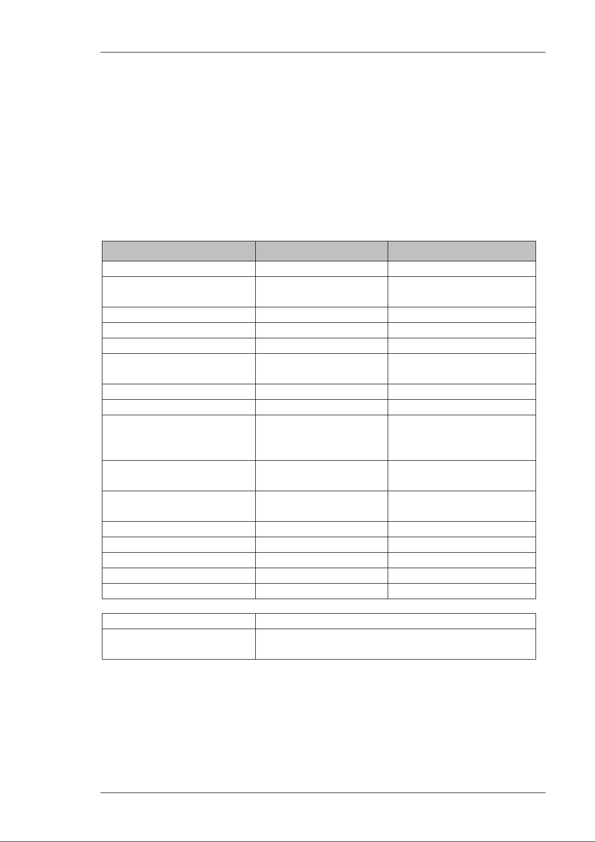
1.5.2 Electrical Specifications
Parameters Downlink Uplink
Frequency Range 851 – 869 MHz 806 – 824MHz
Pass band Gain @Min
attenuation
Operating Bandwidth 18 MHz 18 MHz
Propagation Delay 5 µsec. 5 µsec.
Band Ripple ± 2 dB max ± 2 dB max
1 dB Bandwidth
Channel Rejection
20 dB Bandwidth 22 MHz 22 MHz
Noise Figure @max gain 7.0 dB 7.0 dB
Gain Control Setting (by
RMT software) – User
Defined
3rd Order Output
Intercept Point (IP3 out)
Composite Output
Power
Impedance Level 50 ohms 50 ohms
V.S.W.R In/Out 1.5: 1 max 1.5: 1 max
LO Leakage -13 dBm max. -13 dBm max.
Spurious in band -45 dBc typical -45 dBc typical
Spurious out of band -13 dBm max. -13 dBm max.
Power Supply 110 to 220 VAC
Maximum Consuming
Power
90 dB typical 90 dB typical
18 MHz 18 MHz
30 dB @1 dB/step 30 dB @1 dB/step
+56 dBm typical +45 dBm typical
+36 dBm +1/-0 dB +24 dBm +1/-0 dB
150 W
Page 2 Proprietary Data Pub. 307-2005 Rev. 1.0
DEKOLINK WIRELESS LTD. PRODUCT MANUAL IDEN REPEATER
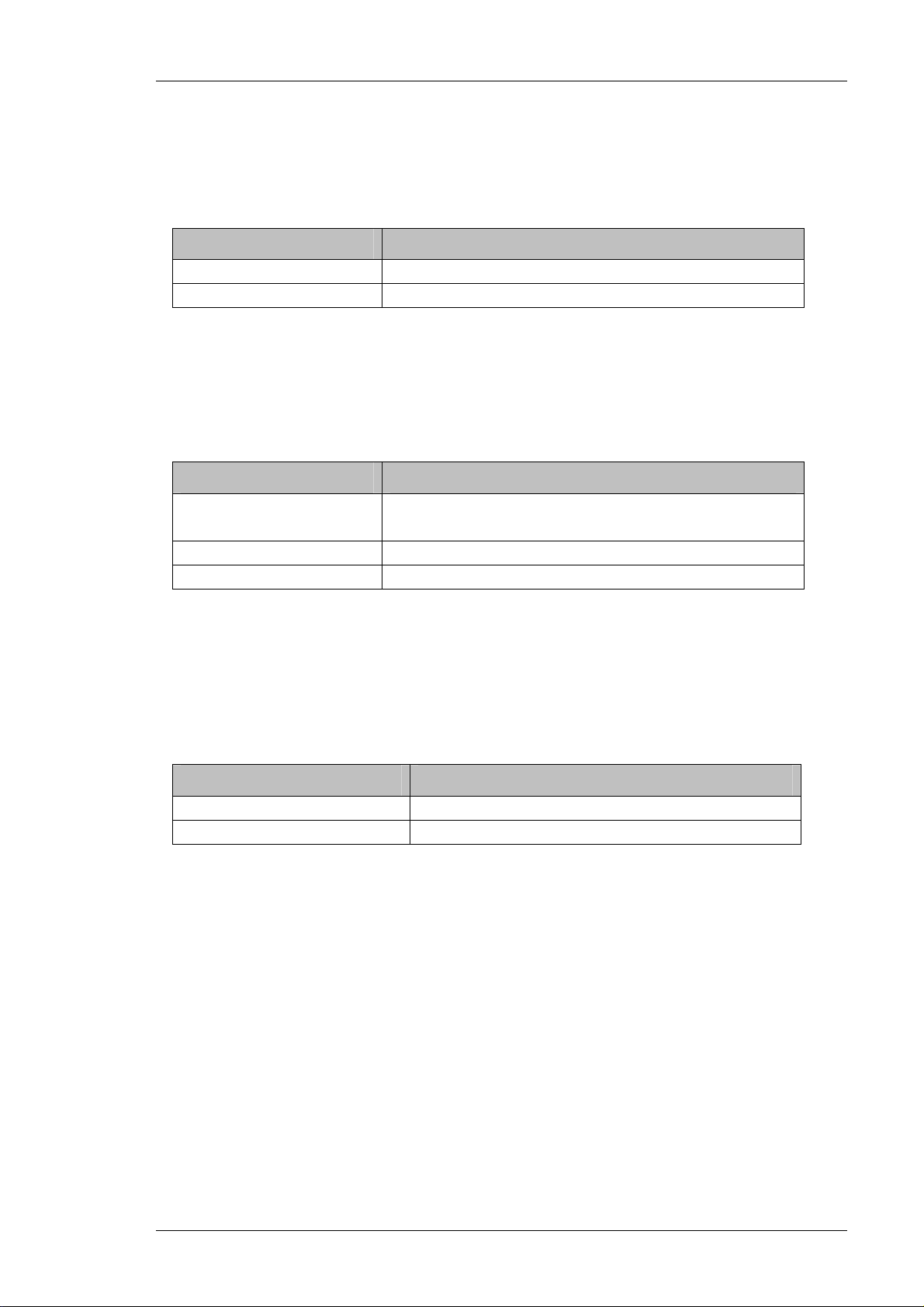
1.5.3 Mechanical Specifications
The following table provides the mechanical specifications of the iDEN Repeater.
Element Value
Size H x W x D 400 x 400 x 260 mm (16 x 16 x 10.3 inch)
Weight Approximately 25 kg. (55 lbs.)
1.5.4 Connectors
The Repeater interfaces with a Base antenna port and a Mobile antenna port. It
includes four external connectors in its bottom panel, as described below.
Connector Type
RF Connectors:
N-type, Female
BASE / MOBILE
AC Circular, 3-pin
Alarms Circular, 8-pin
1.5.5 Environmental Specifications
Dekolink’s iDEN Repeaters meet the European IP65 and American NEMA4
weatherproof standards. The Repeater is designed to operate properly under the
following environmental conditions.
Condition Value
Operating temperature
Storage temperature
- 30° C to + 50°C
- 50° C to + 80°C
Pub. 307-2005 Rev. 1.0 Proprietary Data Page 3

IDEN REPEATER PRODUCT MANUAL DEKOLINK WIRELESS LTD.
1.6 UNPACKING AND INSPECTION
This section provides information for unpacking, inspection and preparation for
installation.
Examine the shipping container for damage before unpacking the unit. Perform a
visual inspection to reveal any physical damage to the equipment.
Verify that the equipment is complete, as listed below and under a packing slip.
Contact Dekolink Wireless Ltd if any of this equipment is missing.
Your Dekolink iDEN Repeater comes with the following equipment:
iDEN Repeater •
•
Key (used to lock the repeater case)
•
AC cable [6 ft.]
•
Alarm cable [6 ft.]
•
RS232 cable [6 ft.]
•
RMT Software Installation CD
•
RMT Software User's Guide and iDEN Repeater Product and
Installation Manual (CD and hardcopies)
•
Acceptance Test Report (A.T.R.)
•
Packaging Box
Please contact Dekolink if you want to order the following optional equipment:
•
AC Cable [30 ft.] – Long cable for AC power
•
Alarm Cable [30 ft.] – Long cable for External Alarms Input
•
Kit for the iR1200 Modem - Mechanical adaptor for the
iR1200 modem installation
Page 4 Proprietary Data Pub. 307-2005 Rev. 1.0
DEKOLINK WIRELESS LTD. PRODUCT MANUAL IDEN REPEATER
2. FUNCTIONAL DESCRIPTION
2.1 GENERAL
This repeater is designed to help improve communications signal by extending the
coverage of a base station. The Donor (Base) antenna receives the signal from a base
station and conveys it to the iDEN Repeater. The Repeater amplifies the signal.
After amplification, the signal is passed through to the Mobile antennas. Conversely,
signals from handsets are amplified and retransmitted by the Repeater to the base
station.
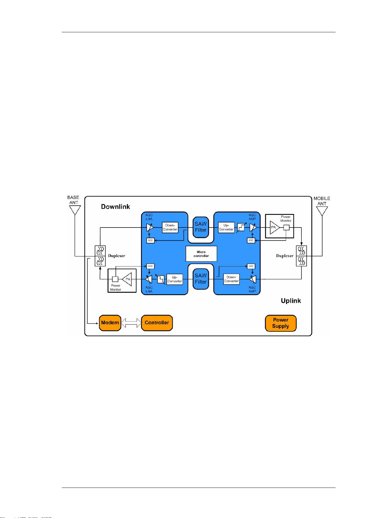
2.2 FUNCTIONAL DESCRIPTION
The incoming signal processing in the iDEN Repeater is processed similarly for both
the Uplink and Downlink paths. Figure 1 provides a functional block diagram of the
iDEN Repeater.
Figure 1: iDEN Repeater - Block Diagram
The block diagram showed in Figure 1 illustrates the overall functionality of the
iDEN Repeater. Dekolink’s programmable iDEN Repeaters employ advanced
up/down conversion Intermediate Frequency (IF) Surface Acoustic Waves (SAW)
filtering architecture. This new technology offers distinct advantages over
conventional repeaters, when high adjacent selectivity and spectrum purity is
required.
The Channeler Module (center unit) consists of dual Radio Frequency Up/Down
Converter sub-modules for Downlink and Uplink paths. The Channeler amplifies the
received RF signals and converts them into an intermediate frequency (IF). The IF
outputs are connected to a SAW Filter. The IF outputs are converted back to the
original RF frequencies.
The cellular modem is an option for remote monitoring and repeater parameters
control.
Pub. 307-2005 Rev. 1.0 Proprietary Data Page 5

IDEN REPEATER PRODUCT MANUAL DEKOLINK WIRELESS LTD.
3. DESCRIPTION
3.1 MAIN COMPONENTS LOCATION
Figure 2 provides the location of the main components of the Repeater. A list
identifying these components is provided below.
Figure 2: iDEN Repeater - Main Components
1. Controller (Control Box - CB) (includes a status LED)
2. Duplexer to Base Antenna (low power)
3. Channeler (Dual Up/Down Converter for Uplink and Downlink
Paths)
4. Power Supply
5. Duplexer to Mobile Antenna (high power)
6. Monitor Module
7. Door Alarm Switch
8. Uplink Power Amplifier
9. Downlink Power Amplifier
10. Coupler for Modem Antenna
11. Wireless/Wireline iDEN Modem Unit – Location
Page 6 Proprietary Data Pub. 307-2005 Rev. 1.0

DEKOLINK WIRELESS LTD. PRODUCT MANUAL IDEN REPEATER
3.2 COMPONENTS GENERAL DESCRIPTION
A description of the main components of the iDEN Repeater follows.
3.2.1 Channeler
The Channeler Module consists of dual Radio Frequency (RF) Up/Down Converter
sub- modules for Downlink and Uplink paths. The Channeler amplifies the received
RF signals and converts them into an intermediate frequency (IF). The IF outputs are
connected to a SAW Filter. The IF outputs are converted back to the original RF
frequencies. The Channeler also has controllable attenuators (32 dB range in steps of
1dB)and a pre-amplifier for each path.
3.2.2 Monitor Module
The Monitor Module measures the current of the following elements of the Repeater:
Up/Down Converter, Uplink Power Amplifier, and Power Supply. It also senses the
Downlink output power. If a module fails, an appropriate report is sent to the Control
Box and the Summarized alarm red LED lights up.
3.2.3 Controller
The Controller (also called Control Box) controls and monitors the parameters in all
modules of the Repeater. It provides local or remote connection to a PC (See
Dekolink’s RMT User's Guide for more information.).
For a more detailed description of the module, refer to paragraph 3.3.
3.2.4 Power Supply
The Power Supply module allows a wide range of input power from different sources:
90 to 260 VAC, maximum power consumption - 150W.
The output power provided to the Repeater internal modules is:
28 VDC, 15VDC and 9 VDC.
3.2.5 Duplexers
The duplexers isolate the transmit path from the receive path. The pass bandwidth of
the duplexer is the entire width of the Uplink band and the Downlink band
respectively.
3.2.6 Power Amplifier
The power amplifier is the final stage of both the Downlink and Uplink paths. The
iDEN Repeater includes Power Amplifiers with relatively high Third Order Intercept
Point (IP3) figures, thus allowing high output power while preserving high linearity
of the output signals.
Pub. 307-2005 Rev. 1.0 Proprietary Data Page 7

IDEN REPEATER PRODUCT MANUAL DEKOLINK WIRELESS LTD.
3.3 REPEATER FEATURES
3.3.1 Controller
The integrated Controller Module (Control Box) has three main functions:
1.
Detects faults in the repeater and issues an alarm indication.
2.
Controls the active components in the Repeater and enables the main
parameters setting :
Max Power
RF Gain,
Power On/Off,
AGC On/Off
SALC On/Off
3.
Monitors key operating functions:
DC supply voltage
Downlink output power
Heatsink temperature.
Two modes of monitoring and control are available:
•
External PC - through the serial interface connector in the Control Box.
•
Remote control - via a modem connected to the Control Box serial interface.
A standard or cellular modem can be installed inside the Repeater enclosure,
refer to Appendix D.
The Repeater’s Alarm, Control and Monitor functions are performed by Dekolink’s
RMT software. For more information, see the RMT User's Guide.
The Controller transmits in two modes: Polling and Burst. When operating in Burst
Alarm mode, the Controller generates a burst alarm and reports the faults to the local
or remote connection. The Controller software handles the alarm reporting and
parameters transmission to the Repeater’s outside world.
3.4 SMART-ALC FUNCTION
3.4.1 SALC Description
The Smart Automatic Level Control (Smart-ALC) is an innovative solution for
automatic repeater gain adjustment. Combined with advanced control algorithms,
SALC can perform gradual learning of traffic load characteristics and adjust the
Repeater RF Gain to the desired value.
This automatic operation practically removes the need to make initial settings for
maximal traffic load conditions and eliminates the need for numerous site visits to
take care of Gain adjustment.
SALC also reduces isolation problems and maintains Uplink/Downlink balance.
Page 8 Proprietary Data Pub. 307-2005 Rev. 1.0

DEKOLINK WIRELESS LTD. PRODUCT MANUAL IDEN REPEATER
3.4.2 ALC Function
The Repeater includes the Automatic Level Control (ALC) function on both the
Uplink and Downlink power amplifiers to prevent output power from exceeding
maximum allowed output power.
The amplifier includes a directional coupler and a detector that monitor the output
power. The ALC mechanism samples the output power, and decouples and rectifies
it. The ALC mechanism sends a feedback signal to a voltage variable attenuator
(VVA) that, whenever a high input signal is received, attenuates the signal level so
that the output power of the amplifier does not exceed the preset limit.
The ALC is factory preset to ON state.
3.4.3 RF Gain Setting
The gain range should be set via the RMT in accordance with the input signal power
at the Donor antenna, and the required Downlink output power. Special care should
be taken not to exceed the isolation limit. It is recommended to set the Downlink
path gain to a maximum value that is 12 dB below the isolation between the Base
antenna and the Mobile antenna.
The gain range is 59-90 dB. Use the Max Gain field for Downlink GAIN setting and
the Gain Delta field to determine the GAIN difference between Uplink and Downlink
path (Uplink GAIN follows Downlink GAIN by “Delta” dB)..
Refer to Section 5.5
Note
When you set the gain to 60 dB the Maximum Output Power will degrade due to
overload input power. The maximum input power you can inject is –25 dBm.
Pub. 307-2005 Rev. 1.0 Proprietary Data Page 9

IDEN REPEATER PRODUCT MANUAL DEKOLINK WIRELESS LTD.
4. INSTALLATION
4.1 SAFETY INSTRUCTIONS
Before installing the repeater, review the following safety information:
Follow all local safety regulations when installing the repeaters. •
•
Only qualified personnel are authorized to install and maintain the repeater.
•
When operating the repeater, it is recommended to keep its cover closed
while the power is on. Some maintenance tasks may require the repeater
door to be opened while the power is on. In such cases, perform the required
tasks carefully and remember to close the repeater cover/door when
finished.
•
Use a suitable mounting surface, such as a rigid wall.
•
Follow Electro-Static Discharge (ESD) precautions.
•
Before closing the repeater cover, make sure no wires are in the way.
•
Install the repeater close to the service area to maintain the output power
and noise figure.
•
Use low loss cables to connect the antennas to the repeater.
•
Install the repeater in a shielded, ventilated, and easy-to-reach area.
4.2 RF EXPOSURE WARNING
4.2.1 General
In order to satisfy the FCC RF exposure requirements, it must be ensured that the
installation complies with the following requirements.
4.2.2 Donor Antenna requirements
The Donor antenna connected to the BASE port in the Repeater is usually installed
outdoor. This antenna (Yagi type or similar) has a 12-20 dBi gain, and features a
very sharp beam pointed to the BTS. Cable and jumper loss is at least 2dB.
The Donor antenna must be installed to provide a minimum separation distance of
0.5 m from any personnel within the area.
4.2.3 Mobile Antenna requirements
The second antenna is connected to the MOBILE port in the Repeater. This interface
serves either an Outdoor antenna or an Indoor antennas array, in accordance with the
application.
In case of Outdoor application, the antenna type is omnidirectional (isotropic)
with 0 to 2 dBi typical gain, or wide beam with up to 10 dBi gain. This antenna is
installed on a mast to cover a shadowed outdoor area. Cable and jumper loss is at
least 2dB. Installation of this antenna must provide a minimum separation distance of
1 m from any personnel within the area.
Page 10 Proprietary Data Pub. 307-2005 Rev. 1.0

DEKOLINK WIRELESS LTD. PRODUCT MANUAL IDEN REPEATER
In case of Indoor coverage, the output power is split into several, omni directional
antenna with 0 to 2 dBi typical gain, and distributed to different indoor areas (in
building floors, tunnels, basements, parking lots, shopping centers etc.). At least 5
such antennas must be connected to the Repeater with cables and splitters.
In this application, the maximum EIRP from each antenna shall not exceed 3W.
Consequently, the minimum required separation distance from any personnel within
the area is 30 cm. Less separation is needed if the power is divided into more than 5
antennas covering many floors or areas.
4.3 REPEATER INSTALLATION SITE VERIFICATION
4.3.1 General
This section provides the required procedures for the verification of the operating
environment of the iDEN Repeater, to be performed before connecting the unit and
before its operation.
4.3.2 Verifying the Link Between the BTS and the Repeater
This test checks the signal strength from the BTS antenna to the iDEN Repeater.
Proceed as follows:
Using Spectrum analyzer, measure the received signal from BTS at the
•
Donor antenna port near the repeater
•
Adjust the Donor antenna direction to receive the maximum signal strength.
•
Compare with the calculated signal strength from the design phase
•
In case of mismatch, check for cause:
- Antenna out of direction
- Antenna tuned to side lobe instead of main lobe
- Antenna connector or antenna cable faulty
- Line of sight problem (obstruction), etc.
•
Register the signal strength of the downlink channel for the system
operation phase.
4.3.3 Verifying the Antenna Isolation
The isolation between the Base/Donor and Mobile/Service antennas is critical
especially for high gain, outdoor applications.
For proper operation of the iDEN Repeater, Dekolink recommends that the isolation
between the Donor and Service antennas be at least 12 dB higher than the repeater set
gain.
Note
Lower isolation can lead to high in-band ripple, oscillations and low Signal Quality
Estimate (SQE) measurements.
To measure the isolation, proceed as follows:
•
Inject a known signal from a signal generator into one antenna (preferably
the Donor antenna)
Pub. 307-2005 Rev. 1.0 Proprietary Data Page 11

IDEN REPEATER PRODUCT MANUAL DEKOLINK WIRELESS LTD.
Measure the coupled output from the Service antenna, using the Spectrum
•
analyzer and LNA if applicable
•
Perform this procedure across the frequency range of the Uplink bands
•
Perform this procedure across the frequency range of the Downlink bands
•
Register the lower result for system operation.
4.4 MECHANICAL INSTALLATION
4.4.1 General
The iDEN Repeater enclosure is a cabinet-like unit, made of heavy metal. It is 40 cm
wide, 40 cm high, 26 cm deep (16 x 16 x 10.2 inches). It weighs approximately 25
Kg (55 pounds)..
4.4.2 Types of Installation
There are two basis types of installation for the Repeater:
•
Wall mount installation – preferred
•
Tower mount installation
The wall mount installation is the preferred method of installation for the Repeater.
The installation procedures for both types are provided below.
WARNING
The Repeater must always be installed vertically and top-down, to allow free-flow
of cooling air. Horizontal installation on a bench for long time may cause damage
to the Repeater due to over-heating.
4.4.3 Wall Mount Installation
Determine the location of the Repeater on the wall. The location should be at normal
eye level height, above ground.
Make sure to allow a depth distance of approximately one meter (around three feet) to
allow the door to swing completely open, and to enable easy access to the Repeater
for maintenance and on-site inspection. The Repeater should be installed in a
ventilated and easy-to-reach area (see Figure 4).
Proceed as follows:
•
Determine the location of the Repeater on the wall
•
Mark the four drilling holes on the surface of the wall based on the
mounting holes on the Repeater chassis – see Figure 3
•
Drill the appropriate four holes in the wall
•
Align the housing so that the mounting brackets fit into the holes in the wall
•
Use tire bolts, hex-head bolts, and M8 washers to secure the enclosure
firmly to the wall.
Note
Bolts and washers are not supplied with the Repeater
Page 12 Proprietary Data Pub. 307-2005 Rev. 1.0

DEKOLINK WIRELESS LTD. PRODUCT MANUAL IDEN REPEATER
4.4.4 Tower Mount Installation
A tower mount adapter should be attached to the antenna tower prior to mounting the
Repeater. The location on the tower and choice of fasteners is governed by local
practice.
Proceed as with the wall mount installation procedure, refer to paragraph 4.4.3.
Pub. 307-2005 Rev. 1.0 Proprietary Data Page 13

IDEN REPEATER PRODUCT MANUAL DEKOLINK WIRELESS LTD.
Figure 3: iDEN Repeater - Dimensions
Figure 45: iDEN Repeater – Typical Outdoor Installation
Page 14 Proprietary Data Pub. 307-2005 Rev. 1.0

DEKOLINK WIRELESS LTD. PRODUCT MANUAL IDEN REPEATER
4.5 CABLES CONNECTION
4.5.1 General
Once the Repeater is installed, you are required to connect the cables from the
antennas and to plug to the power supply.
4.5.2 RF Cables Deployment
The RF interface between the Repeater and the antennas is supported by one (donor
and service) pair of N-type female connectors mounted on the Repeater bottom panel.
CAUTION
We recommend NOT to connect the antenna cables to the Repeater at this stage.
They shall be connected with RF Coaxial Jumpers at the activation step.
See Section
Use the following procedures to connect the coaxial cables to the Repeater:
•
5.6.
Connect the Donor antenna to the BASE port (N-type female connector) in
the Repeater lower connectors’ panel (see Figure 5)
• • Connect the Service antenna to the MOBILE port (N-type female connector)
in the Repeater lower connectors’ panel
Dress the exterior coaxial cables with insulation and holding tape (Type 3M
Rubber splicing tape) for environmental protection and to ensure longer
lifetime.
Note
The recommended coaxial cables are weather-resistant type, and therefore this
procedure is not necessary.
Figure 5: iDEN Repeater – Bottom Panel
Pub. 307-2005 Rev. 1.0 Proprietary Data Page 15

IDEN REPEATER PRODUCT MANUAL DEKOLINK WIRELESS LTD.
4.5.3 Power Cable Connection
The repeater operates from a power source of 110V/220 VAC. The maximum
consumption power is 150W.
Danger: Electrical Shock
This equipment is usually installed outdoors. Wet conditions increase the
potential for receiving an electric shock when installing or using electrically
powered equipment. To prevent electrical shock when installing or modifying
the system power wiring, disconnect the wiring at the power source before
working with uninsulated wires or terminals.
CAUTION
Take all the necessary precautions against Electro-Static Discharge (ESD).
Proceed as follows:
Locate the AC power outlet, with at least a 6A slow blow fuse •
• • Connect the AC power cable from the AC power outlet to the POWER
connector in the Repeater. The repeater automatically turns on
(see Figure 5).
The green Led at the Repeater front panel turns on as an indication of power
supply on (there is no On/Off switch).
Page 16 Proprietary Data Pub. 307-2005 Rev. 1.0

DEKOLINK WIRELESS LTD. PRODUCT MANUAL IDEN REPEATER
5. OPERATING INSTRUCTIONS
5.1 GENERAL
This section provides the operating instructions for the Digital Repeater. The
operating instructions require the use of the Repeater Management Tool (RMT)
software.
5.2 REPEATER MANAGEMENT TOOL (RMT)
5.2.1 General
The Repeater Management Tool (RMT) software supplied with the iDEN Repeater
provides full access to all control settings and monitoring capabilities. The RMT
software can be installed on Windows 95, Windows 98, Windows 2000, and
Windows XP operating systems.
This software tool is used to manage, monitor and control the repeater locally via a
serial connection or remotely through a modem. See the RMT User's Guide for more
information.
5.2.2 Software Installation
The RMT is activated by the RMT software package.
Install the RMT Software from the supplied CD to your laptop. For detailed
•
instructions, refer to the Repeater Management Tool User's Guide
P/N: 300MB40080.
•
The Repeater Management Tool icon will appear on your desktop.
5.3 LAPTOP LOCAL CONNECTION
To set up a local connection to a Laptop:
•
Open the Repeater door and identify the Controller.
•
Connect the Repeater to the Mains (if not already done) and wait for the
power LED on the Controller to begin flashing rapidly.
•
Connect an external serial cable (RS232) from the Laptop to the Controller
P3 (RS232) connector (see Figure 6). Make sure that the status led on the
Controller is blinking before you connect the cable.
Pub. 307-2005 Rev. 1.0 Proprietary Data Page 17

IDEN REPEATER PRODUCT MANUAL DEKOLINK WIRELESS LTD.
Figure 6: iDEN Repeater - Local Monitoring with Laptop
5.4 PC REMOTE CONNECTION
To set up a remote connection to a PC (see Figure 7):
1. Install a modem in the iDEN Repeater and connect it to the Controller P3
(RS232) connector or
2. Connect a wireless external modem to the Controller P3 (RS232) connector
Figure 7: iDEN Repeater - Remote Monitoring and Control Connection Diagram
See Appendix D: Modem Installation for further installation procedures.
Page 18 Proprietary Data Pub. 307-2005 Rev. 1.0

DEKOLINK WIRELESS LTD. PRODUCT MANUAL IDEN REPEATER
5.5 REPEATER INITIALIZATION PROCEDURES
To initialize and setup the iDEN Repeater parameters, proceed as follows:
3. Turn on the Laptop or the PC (for remote configuration)
4. Activate the RMT from the Start menu or by double clicking the Repeater
Management icon on your desktop
1. The following startup screen is displayed.
2. Click on the Temp Unit button as follows. Make sure that the “Repeater PN"
is correct (Please refer to the RMT User's manual to set the required PN).
3. Click on the Connect button as follows.
Pub. 307-2005 Rev. 1.0 Proprietary Data Page 19

IDEN REPEATER PRODUCT MANUAL DEKOLINK WIRELESS LTD.
4. The following Connection screen is displayed. To select the mode of
operation for configuration, proceed as follows:
5. After accessing the Repeater, the Password window appears. Enter the
Repeater’s password (the default password for the repeater is "password".
Click OK.
password
6. The main setup screen is displayed. It consists of three sub-screens accessible
by clicking on the appropriate tab: Repeater Alarms / Params and Control /
Configuration. The Repeater PN is provided on the right-most upper area for
identification of the Repeater.
7. First verify the Repeater identification data in the Configuration screen as
shown below. Confirm that the data is correct. Enter the Server Phone
number and change Unit Password if necessary.
Page 20 Proprietary Data Pub. 307-2005 Rev. 1.0

DEKOLINK WIRELESS LTD. PRODUCT MANUAL IDEN REPEATER
Note
The changed parameter are colored in red. They turn black after updating.
8. Click the Send Parameters button (not shown above) to update the data.
9. Continue the definition procedure by clicking on the Params. And Control
tab. Set the options and check data in two steps as described below.
Pub. 307-2005 Rev. 1.0 Proprietary Data Page 21

IDEN REPEATER PRODUCT MANUAL DEKOLINK WIRELESS LTD.
Page 22 Proprietary Data Pub. 307-2005 Rev. 1.0

DEKOLINK WIRELESS LTD. PRODUCT MANUAL IDEN REPEATER
10. Proceed with the definition procedure by clicking on the Repeater Alarms
tab. Perform as described below.
The iDEN Repeater is now loaded with its own configuration.
Pub. 307-2005 Rev. 1.0 Proprietary Data Page 23

IDEN REPEATER PRODUCT MANUAL DEKOLINK WIRELESS LTD.
5.6 REPEATER ACTIVATION PROCEDURES
To activate the iDEN Repeater parameters, proceed as follows:
1. Use the following procedures to connect the coaxial cables to the
Repeater:
Connect the Donor antenna to the BASE port (N-type female connector) in
•
the Repeater lower connectors panel (see Figure 5)
• Connect the Service antenna to the MOBILE port (N-type female
connector) in the Repeater lower connectors panel
2. Click on the Params. And Control tab. Set the options and check
data as described below.
3. Click on the Repeater Alarms tab. Check the status of the Leds -
All Leds should be colored green except the “Door Open” in red.
4. Test the performance of the system in the coverage area (drive test)
5. Disconnect the RS-232 cable from the Repeater and close the door
with the supplied key.
The Repeater is up and running.
Page 24 Proprietary Data Pub. 307-2005 Rev. 1.0

DEKOLINK WIRELESS LTD. PRODUCT MANUAL IDEN REPEATER
6. MAINTENANCE AND TROUBLESHOOTING
6.1 GENERAL
This section provides the maintenance and troubleshooting procedures for the iDEN
Repeater.
6.2 PERIODIC MAINTENANCE
There is no periodic maintenance required for the iDEN Repeater. As long as it is
installed in a shaded area and not subject to extreme temperatures, it will provide long
term, carefree operation.
6.3 VISUAL INSPECTION
During normal operation, the POWER lamp is on. If the POWER lamp is off, check
the Mains power supply.
6.4 ALARMS AND TROUBLESHOOTING
6.4.1 Alarms
In case of general failure, the Repeater issues an alarm to warn for malfunction. This
alarm is issued from the Alarms connector (Open for alarm indication).
To display the Repeater Alarms screen:
1. Connect the Repeater to a Laptop – refer to paragraph 5.3 or
2. Connect the Repeater to a remote PC – refer to paragraph 5.4
3. Display the Repeater Alarms screen – refer to paragraph 5.5
4. In accordance with the lit LED, perform the troubleshooting
procedures as described below – refer to paragraph 6.4.2.
Figure 8: iDEN Repeater - Repeater Alarms Screen
Pub. 307-2005 Rev. 1.0 Proprietary Data Page 25

IDEN REPEATER PRODUCT MANUAL DEKOLINK WIRELESS LTD.
6.4.2 Troubleshooting
The following table summarizes various error/warning alarms and indications (see
Figure 8), their possible cause, and a course of action to correct the problem.
Alarm Indication Probable Cause Recommended Action
Downlink Power
Amplifier FWD
Measurement
(this is not a fault)
Uplink Power
Amplifier Uplink
Current
Measurement
Downlink VSWR
[Return Power]
Downlink / Uplink
Channeler Current
Composite output
power is below the
threshold value
- Check the Donor antenna
connection.
- Check that the Donor antenna
alignment is in line of sight
with the Base station.
- Increase the RF Gain.
Power Amplifier
Fault
High Voltage
Standing Wave Ratio
(VSWR) at the
Mobile port
- Mute the Uplink Power
amplifier. Turn it back on (*).
- Check the antenna and cable
connection at the Mobile port.
- Replace the antenna if
necessary.
Channeler failed - Check if a temperature alarm
is active. If so, see the
Temperature alarm below.
- Check if the Lock Detect
alarm is active. If so, see the
Lock Detect alarm below.
- Decrease the gain of the
Repeater to minimum, check
the alarm, and turn it back to
Maximum Gain (*).
Temperature Indicates an inner
temperature over
60ºC.
The power supply
shutdowns the
- Verify that the repeater is
mounted correctly, with the
Repeater gland plate facing the
floor.
- Increase ventilation.
Repeater when the
temperature reaches
70ºC
Door Open Indicates that the
Repeater door is open
- Close the Repeater door.
- Check the connection of the
door switch.
Page 26 Proprietary Data Pub. 307-2005 Rev. 1.0

DEKOLINK WIRELESS LTD. PRODUCT MANUAL IDEN REPEATER
Alarm Indication Probable Cause Recommended Action
Fan Failure Fan Failed - Check power supply
- Check fan.
External Alarm Connectivity - Check connection to Alarms
connector.
Downlink/Uplink
Lock Detect alarm
Faulty status of the
Phased Locked Loop
(PLL) in the
Channeler unit
- Reboot the Repeater.
- Check the connection
between the Controller and the
Channeler (*).
(*) If the indication remains after the Recommended action procedure, replace the
Repeater.
The following troubleshooting procedures refer to communication failures, and are
not shown in the Repeater Alarms screen.
Failure Probable Cause Recommended Action
Connection to the
Controller failed in
the local connection
Communication
failure
- Check the physical connection
between the PC COM1 and the
Controller RS232 interface.
- Verify that the LED of the
controller is blinking rapidly.
- Reboot the Repeater.
- Restart the PC.
- Re-install the Controller software
Connection with
the Repeater failed
in the remote
connection
Communication
failure
- Check that the modem is physically
connected to the controller serial
input.
- Verify that the modem local port
baud rate is 57,600 bps.
- Verify that the Controller LED is
blinking.
- Verify that the modem is connected
to the antenna cable via the RF
coupler.
- Restart the PC.
- Reinstall the Controller software.
Pub. 307-2005 Rev. 1.0 Proprietary Data Page 27

IDEN REPEATER PRODUCT MANUAL DEKOLINK WIRELESS LTD.
APPENDIX A: MECHANICAL OUTLINE
This appendix contains the mechanical outline of the Repeater.
iDEN Repeater - Mechanical Outline
Figure 9: iDEN Repeater – Mechanical Outline
Page 28 Proprietary Data Pub. 307-2005 Rev. 1.0

DEKOLINK WIRELESS LTD. PRODUCT MANUAL IDEN REPEATER
iDEN Repeater – Connectors Panel Mechanical Outline
The following figure shows the connectors panel layout for Repeater Model Number:
MW-CSR-ESMR-25W90
Figure 10: iDEN Repeater – Connectors Panel Layout
Pub. 307-2005 Rev. 1.0 Proprietary Data Page 29

IDEN REPEATER PRODUCT MANUAL DEKOLINK WIRELESS LTD.
A
APPENDIX B: EXTERNAL ALARMS CONNECTOR PINOUT DEFINITION
The following table details the pinout definition of the ALARMS connector located
in the gland plate of the repeater.
Letter Description Color Code
A External Alarm Input (1) White
B N/C N/C
C N/C N/C
D Summarized Alarm Dry Contact Red
E Summarized Alarm Dry Contact Green
F N/C N/C
G N/C N/C
H External Alarm Input (2) Black
Figure 11: Alarms Connector – Pinout
H
G
F
E
D
B
C
Page 30 Proprietary Data Pub. 307-2005 Rev. 1.0

DEKOLINK WIRELESS LTD. PRODUCT MANUAL IDEN REPEATER
APPENDIX D: MODEM INSTALLATION (OPTION)
General
The iDEN Repeater is ready for connection of a serial, Hayes Compatible, AT
Command type modem with a phone number to allow connection in a circuit
switched network.
If you are using a modem with a SIM card, special settings (network or terminal
definitions) may be needed to allow data transmission.
Modem Installation
Perform the following steps to install a standard modem:
•
•
Connect the modem to the power supply. •
Install the modem with a straight serial cable. This cable is usually supplied
with the modem. (See the tables below for the pinout description.)
Use a PC with the same terminal mode and bit rate as the default modem
baud rate. For example, 57,600, 19,200, 14,400 bps or other baud rate
depending on the modem default configuration.
Use the following commands:
•
AT S0=0 <ENTER>
•
AT+IPR=57600 <ENTER>
•
Change terminal baud rate to 57,600 bps if necessary.
•
Use the PC in terminal mode to save the new baud rate settings.
Use the following commands:
•
D AT&W1 <ENTER> (For some modems)
•
AT&W0 <ENTER> (For other modems)
•
Disconnect the serial cable from the PC and connect it to the Controller in
the Repeater.
•
Connect the antenna cable to the modem antenna port. (When testing the
unit in a laboratory, connect the modem to an external antenna) Refer to
Appendix C for more information.
•
Connect the modem to a Power Supply unit terminal.
•
Turn the Repeater AC power on.
•
Use a PC with a wireless or Plain Old Telephone System (POTS) modem
and the Dekolink RMT software to monitor the repeater.
•
Refer to the RMT User's Guide for more information on how to establish
remote connection with a repeater.
Pub. 307-2005 Rev. 1.0 Proprietary Data Page 31

IDEN REPEATER PRODUCT MANUAL DEKOLINK WIRELESS LTD.
Connector Pin-out
Serial Cable Pin-out for Local Communication between the PC and the Controller:
PC Pinout CB Pinout
2 3
3 2
5 5
D-Type 9 Pin female D-Type 9 Pin female
Serial Cable Pinout for Remote Communication between the Modem and the
Controller:
DCE Modem DTE Controller
1 1
2 2
3 3
4 4
5 5
6 6
7 7
8 8
9 9
D-Type 9 Pin female D-Type 9 Pin male
Page 32 Proprietary Data Pub. 307-2005 Rev. 1.0

DEKOLINK WIRELESS LTD. PRODUCT MANUAL IDEN REPEATER
APPENDIX E: DEKOLINK WIRELESS LIMITED WARRANTY
Dekolink Wireless [Ltd.] (“Dekolink”), manufacturer of this product (the “Product”)
warrants to the original purchaser (“Purchaser”) that the Product is free from defects
in materials and workmanship for a term that ends on the earlier of twelve (12)
months from the date of activation of the Product or fifteen (15) months from the date
of shipment of the Product by Dekolink. The obligations of Dekolink under this
warranty shall be limited solely to the repair or exchange or giving credit for, at the
option of Dekolink, any Product that may prove defective in accordance with
evidence satisfactory to Dekolink. Any repair or replacement of the Product by
Dekolink shall not extend the original warranty period. This warranty is exclusive to
the original Purchaser and is not assignable.
This warranty applies only upon the condition that the Product has been installed,
maintained and operated under conditions of normal use. The provisions of this
warranty shall not apply if, in Dekolink’s judgment, the Product has been subject to
misuse or neglect, damaged in an accident or by act of vandalism, or repaired or
altered in any way that adversely affects its performance or reliability.
To obtain warranty service, Purchaser may, upon the prior written authorization of
Dekolink or its authorized service representative, return the defective Product to
Dekolink’s authorized service center. All shipping and insurance charges are the sole
responsibility of Purchaser and are not included in this warranty.
Dekolink expressly excludes and disclaims all other warranties, including but not
limited to any warranties of merchantability or fitness for a particular purpose.
Dekolink shall in no event be liable for any special, indirect, incidental, consequential
or punitive damages or for loss, damage, or expense, including loss of use, profits,
revenue, or goodwill, directly or indirectly arising from purchaser’s use or inability to
use the merchandise, or for loss or destruction of other property or from any other
cause, even if Dekolink has been advised of the possibility of such damage. Some
states do not allow the exclusion or limitation of incidental or consequential damages
so these limitations may not apply under certain circumstances.
The liability of Dekolink shall in no event exceed an amount equivalent to the
purchase price paid by the purchaser for the defective product.
This warranty shall not be extended, altered or varied except by a written instrument
duly signed by Dekolink.
Pub. 307-2005 Rev. 1.0 Proprietary Data Page 33
 Loading...