

Page 1

p
Installation
and
Operating Instructions
for
MW-CBDA-SMR-800-900-1W80
Dual Band
Compact Bi-Directional Amplifier
Dekolink Wireless Proprietary and Confidential Information. Copying, Distribution, and Disclosure are
D
ekolink Wireless Ltd.;16 Bazel St.Qiryat-Arieh Petah-Tikva Israel, 49510
Tel- 972-3-918
rohibited without Express Authorization from Dekolink Wireless Company.
0-180; Fax-972-3- 190-9180 ;
This document is protected by all applicable copyright laws.
omWeb site- www.dekolink.c rev 1 11/04
Email-marketing@dekolink.com;
page 1 of 16
Page 2
Table of Contents
Paragraph Page No
CBDA Overview 3
Main Characteristics 3
Top Cover Alarm Indications 3
Remote Alarm Connector (back panel) 4
CBDA Indications and Control ( side windows) 4
Block Diagram Description 4
RF Block Diagram 5
Step Attenuator and RF Gain Setting 5
AGC Function 6
AGC & Gain Controls 6
AGC Amplifier Layout 6
CBDA Monitor and Alarm 7
CBDA Monitor and Alarm Function Block Diagram 8
CBDA Installation 9
Base / Donor Antenna Installation 9
Remote / Service Antenna Installation 9
Antenna Isolation 9
Installation Steps 10
Diagnostics Guide 11
Top Cover LED Indications 11
RF Faults and RF Power Amplifiers LED Indications: 12
Electrical Specifications 13
Environmental Conditions 14
Mechanical Specifications 14
RF Exposure Warning 14
Mechanical Outline
Dekolink Wireless Limited Warranty
15
16
Dekolink Wireless Ltd.;16 Bazel St.Qiryat-Arieh Petah-Tikva Israel, 49510
Tel- 972-3-9180-180; Fax-972-3- 190-9180 ;
Web site- www.dekolink.com rev 1 11/04 page 2 of 16
Email-marketing@dekolink.com
;
Page 3
CBDA Overview
The Compact Bi-Directional Amplifier (CBDA) assembly provides exceptional
repeater/booster performances to extend the coverage area of radio
communications in buildings and RF shielded environments.
ain CharacteristicsM
• Covers both SMR 800 and SMR 900 in one product.
• 80 dB RF gain
• Over 24 dBm (1/4 Watt) downlink composite power.
• Alarm indication by LED and Dry contact
• Automatic power limit option
• Exceptionally high linear operation
• Ideal for in-building coverage solutions
• Relative small size and light weight
• Cost effective solution
• Wall mounted easy Installation
• Reliable operation, maintenance free
Top Cover Alarm Indications
PWR: Power on green LED
UL: Illuminates at uplink power amplifier current fault
Downlink RF power fault. Illuminates when the DL transmitted power is
DL:
less than +15 dBm.
Dekolink Wireless Ltd.;16 Bazel St.Qiryat-Arieh Petah-Tikva Israel, 49510
Tel- 972-3-9180-180; Fax-972-3- 190-9180 ;
Web site- www.dekolink.com rev 1 11/04 page 3 of 16
Email-marketing@dekolink.com
;
Page 4

Remote Alarm Connector (back panel)
Dry contact relay arms are connected to this D9 connector. The relay arms
switch over at either one of the two alarms indicated on the top cover.
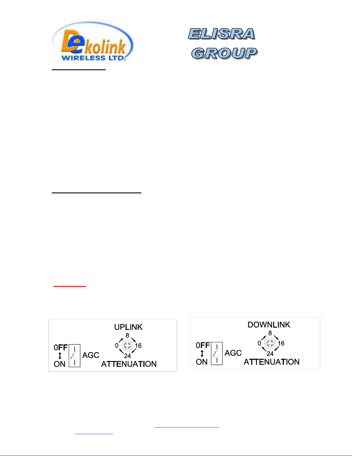
)dowsside win(CBDA Indications and Control
These are reached by opening the window on the sides of the CBDA
AGC LED: This red led illuminates when the transmitted power is equal or higher
than the composite power (factory preset at +24 dBm and DL).
AGC ON/OFF switch: Turns on the automatic power control.
Warning: The AGC switch must be always ON in order to limit the spurious
signals.
Step attenuator: The CBDA gain can be stepped down by the amount indicated
on the step attenuator.
lock Diagram DescriptionB
The CBDA Downlink path receives TX signals from base station amplifies them
and transmits them to the subscriber. The CBDA Uplink path receives RX
signals from the subscriber amplifies them and transmits them to the base
station. Two quad filter assemblies frequency separate the signals to the proper
amplifying path and isolate the two signals.
Each path has two amplifiers; a low noise amplifier (LNA) and a high power
amplifier. The low noise amplifier has a 30 dB step attenuator, which is used to
set the repeater gain.
The power amplifiers in the CBDA have an AGC option switch. They also have a
Power LED lamp that illuminates when the output power has reached the preset
power limit.
Dekolink Wireless Ltd.;16 Bazel St.Qiryat-Arieh Petah-Tikva Israel, 49510
Tel- 972-3-9180-180; Fax-972-3- 190-9180 ;
Web site- www.dekolink.com rev 1 11/04 page 4 of 16
Email-marketing@dekolink.com
;
Page 5
To Base
935 to
941 MHz
851 to
866 MHz
896 to
902 MHz
806 to
821 MHz
Quad F ilter
Assy
TX
RX
Attenuator
LNA
Downlink
Power
Monitor
PA
AGC
Uplink
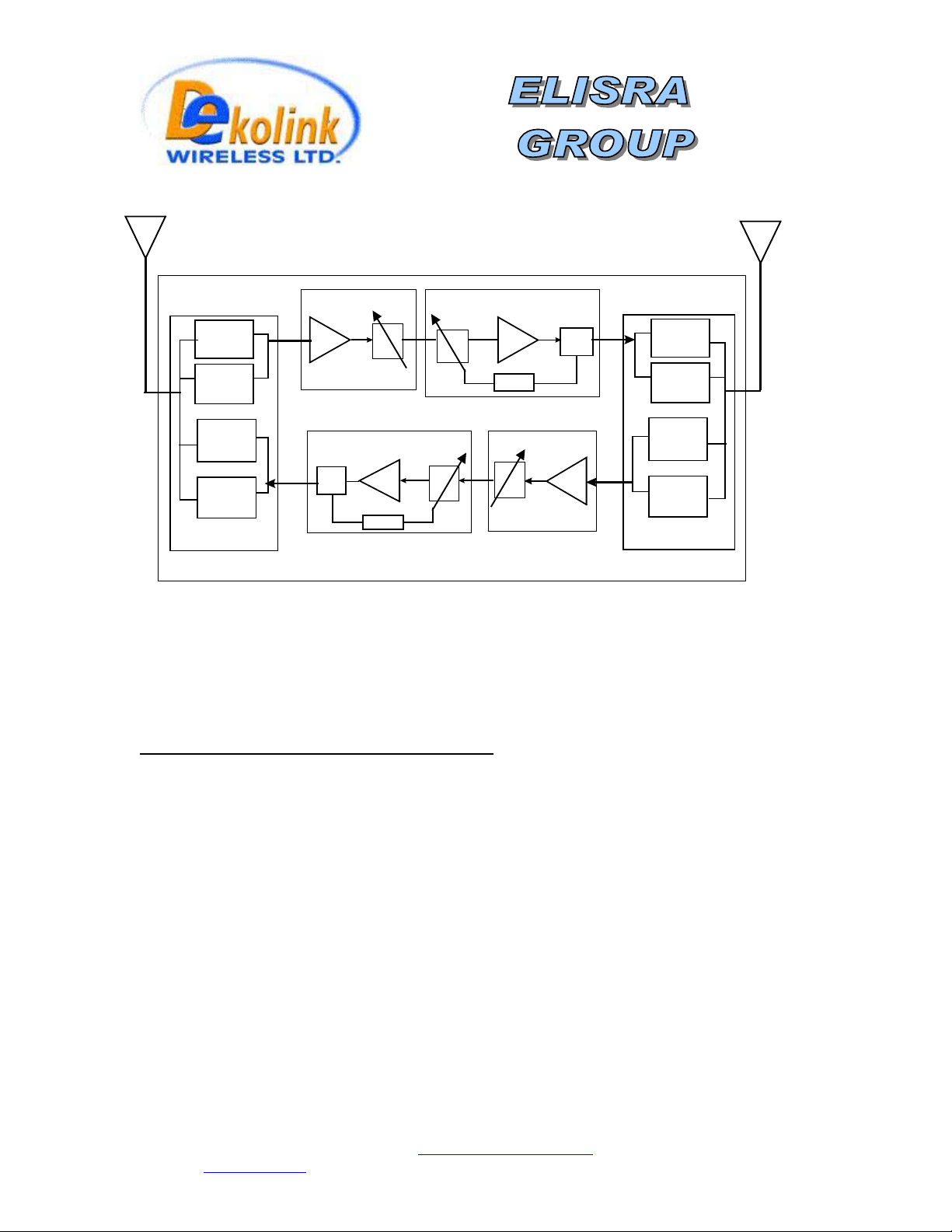
RF Block Diagram
Step Attenuator & RF Gain Setting
PA
AGC
Attenuator
Power
Monitor
LNA
TX
RX
To Service
Area
935 to
941 MHz
851 to
866 MHz
896 to
902 MHz
806 to
821 MHz
Qua d F ilter
Assy
For proper operation of the CBDA; the isolation between the base station
antenna and the mobile antenna should exceed the CBDA gain by at least 12
dB. If the CBDA gain were higher than the isolation between the antennas,
oscillation would start and would saturate the amplifier. Isolation few dB higher
than the CBDA gain cannot start oscillations but would cause gain ripple in the
band.
The step attenuator on the low noise amplifier can reduce the CBDA gain. The
CBDA gain can be stepped down by the amount indicated on the step attenuator
0 to 30 dB in 2 dB steps).
(
Dekolink Wireless Ltd.;16 Bazel St.Qiryat-Arieh Petah-Tikva Israel, 49510
Tel- 972-3-9180-180; Fax-972-3- 190-9180 ;
Web site- www.dekolink.com rev 1 11/04 page 5 of 16
Email-marketing@dekolink.com
;
Page 6
AGC Function
The CBDA has AGC function on both paths that serve to prevent the saturation of the
power amplifier. Their amplifier has a directional coupler and a detector at the output of
the high power amplifier monitoring the output power. When a high signal is received
the automatic level control detects the amplitude and sends a feedback signal to a
voltage variable attenuator, which attenuates the signal level so that the output power of
the amplifier does not exceed the preset limit. The LED on the amplifier illuminates
when the power out the amplifier is within the set limit (when the AGC is On and when
the AGC is OFF).
The switch on the RF amplifier enables the AGC function. If the AGC is disabled then
the amplifier gives maximum gain and maximum power.
AGC and Gain Controls
The AGC and GAIN SETTING functions for the up link path are reached by opening the
small slide door located on the CBDA left side, adjacent to the BASE antenna port. For
the down link path the door is on the right side adjacent to the MOBILE antenna port
RF Power LED: The LED illuminates when the output power exceeds the AGC Set.
AGC ON / OFF Switch: When OFF the amplifier works with its highest gain (AGC
Function OFF). When set to ON (AGC Function ON) the amplifier power output cannot
exceed the set limit.
Warning: The AGC switch must be always ON in order to limit the spurious signals.
Gain setting: By using the rotary knob, the attenuation can be adjusted from 0 to 30
dB in 2 dB steps.
Dekolink Wireless Ltd.;16 Bazel St.Qiryat-Arieh Petah-Tikva Israel, 49510
Tel- 972-3-9180-180; Fax-972-3- 190-9180 ;
Web site- www.dekolink.com rev 1 11/04 page 6 of 16
Email-marketing@dekolink.com
;
Page 7

CBDA Monitor and Alarm
The two main active elements are the Downlink Power Amplifier and the Uplink power
amplifier. Each CBDA has a monitor circuit to monitor these elements and give alarm
signal when there is a deviation from normal operation. The summarized alarm output of
the monitor card is sent to a D-type connector on the front panel.
The monitor circuit performs the following functions:
• Monitors the current of uplink power amplifier. If the current is below or above the
specified limits then an automatic alarm function is provided by a LED on the
CBDA cover which illuminates and by dry contacts of a relay.
• Monitors the downlink RF output power. If the output power is over 10 dB below
the rated value then an alarm function is provided by a LED on the CBDA cover
which illuminates and by dry contacts of a relay.
• The relay arms are normally open, they close when power goes on (at no faults).
Whenever any fault occurs or when the power is cut off from the CBDA the relay
arms open. The relay arms are connected to pins 2,4 of a 9 pin D type male
connector on the front panel of the CBDA for remote sensing of faults.
Pin 2 and 3 of the D type connector provide complimentary relay alarm function;
short at fault and open at no fault.
• The alarm LEDs (red) are displayed on the CBDA cover. The green led is power
on indication.
Dekolink Wireless Ltd.;16 Bazel St.Qiryat-Arieh Petah-Tikva Israel, 49510
Tel- 972-3-9180-180; Fax-972-3- 190-9180 ;
Web site- www.dekolink.com rev 1 11/04 page 7 of 16
Email-marketing@dekolink.com
;
Page 8

8 Pin
Connector
CBDA Monitor and Alarm Function
Green LED
Red LED
Red LED
Power On Indication
UL Power Amplifier
DL Low RF
Power Alarm
To pin 2 of D9 Alarm
To pin 3 of D9 Alarm
To pin 4 of D9 Alarm
DL RF Power
Detection
(from DL Power
Amplifier)
Sum of all
Alarms
Block Diagram
+28 V
+28 V
Current
Sensor
Power
Sensor
Current Alarm
To UL Power Amplifier
DC Supply
Summary
connector
connector
connector
Fault Position)
Alarm
(Shown at
Alarm relay connection to D connector:
Pin 2 to 4 open at any fault; short at no fault
Pin 2 to 3 short at any fault; open at no fault
Dekolink Wireless Ltd.;16 Bazel St.Qiryat-Arieh Petah-Tikva Israel, 49510
Tel- 972-3-9180-180; Fax-972-3- 190-9180 ;
Web site- www.dekolink.com rev 1 11/04 page 8 of 16
Email-marketing@dekolink.com
;
Page 9
CBDA Installation
Install the CBDA Repeater in a shielded, ventilated and easy to reach area. Use low loss cables
to connect antennas to the CBDA. Install the CBDA close to the service area to improve output
power and noise figure. Mount the CBDA with RF connecters pointing down. The RF connection
is made via two type “N” female connectors. The RF connector labeled “Base” must be
connected to the antenna; usually a Yagi; pointing to the base station. The RF connection
labeled “Mobile” must be connected to the antenna pointing into the area to be covered by the
CBDA.
: For cooling purposes The CBDA must be installed with the RF connectors facing down.
Note
Donor Antenna Installation/ Base
Typically this is a directional antenna such as Yagi or Dish antenna of 10 to 15 dB gain. This
antenna is pointed to the base station to get maximum input power. This antenna should be in
line of sight with the base site. Raise this antenna higher if no line of sight is achieved. The
required Base signals should be the dominant signals; at least 6 dB higher power than other
signals.
Choose the antenna site to get the maximum isolation from the remote (mobile serving) antenna.
Service Antenna Installation/ Remote
The remote antenna is an Omni antenna or a directional antenna according to the coverage
requirements.
For indoor applications covering a large building, the RF signals are split using power dividers
and distributed to many antennas each covering a floor or a small area.
Antenna Isolation
For proper operation the isolation between these two antennas must be at least 12 dB higher
than the CBDA gain. Lower isolation would lead to high in-band ripple. Oscillations will build up
when the isolation is lower than CBDA gain.
The isolation between the antennas is critical for high gain outdoor repeaters.
To measure the isolation; inject a known signal into one antenna and measure the power at the
other antenna. This should be done across the frequency range of both uplink and downlink
bands.
Dekolink Wireless Ltd.;16 Bazel St.Qiryat-Arieh Petah-Tikva Israel, 49510
Tel- 972-3-9180-180; Fax-972-3- 190-9180 ;
Web site- www.dekolink.com rev 1 11/04 page 9 of 16
Email-marketing@dekolink.com
;
Page 10

Installation Steps
1. Install all antennas and connect them to the CBDA inputs.
2. Open the access windows at the sides of the CBDA so that the variable attenuator is
reached and the LED is visible.
Turn the AGC On. This AGC limits the output power of the CBDA. The AGC on the Downlink
path guarantees constant downlink power when and if the Donor power changes.
Warning:
3. Set downlink gain to minimum; uplink gain to minimum (by increasing the attenuation).
4. Increase the downlink channel gain (by decreasing the attenuation) till the LED turns from off
to on. This is the best gain setting giving highest usable power. Higher gain setting will
overdrive the AGC circuit.
5. The LED on the downlink power amplifier will illuminate if adequate donor (composite) power
has reached the CBDA. If the donor power is low the LED will not lit and the CBDA usable
power is not used efficiently.
6. The RF power alarm LED on the CBDA cover will lit if the downlink power is over 10 dB
below the composite power.
7. Set the uplink gain to the same as the downlink gain.
8. Check that the uplink LED on the CBDA monitor does not lit permanently. This LED would lit
permanently If the isolation between antennas is low (CBDA oscillations) or the CBDA is
faulty.
9. If the uplink LED light permanently then:
The AGC switch must be always ON in order to limit the spurious signals.
• Disconnect one of the cables from the CBDA connectors and connect a load at the
connectors.
• If the LED on this amplifier illuminates permanently then the CBDA is faulty
(oscillating) and needs replacing.
• If the LEDs stops illuminating then the isolation between the donor and remote
antennas is low. Either improve the isolation (e.g. increase separation) or reduce
CBDA gain.
• To reduce gain, reconnect the antenna cables. Reduce the gain at both uplink and
downlink path until this LED stops illuminating. Reduce the gain further by 10 dB.
This is the maximum usable gain.
Dekolink Wireless Ltd.;16 Bazel St.Qiryat-Arieh Petah-Tikva Israel, 49510
Tel- 972-3-9180-180; Fax-972-3- 190-9180 ;
Web site- www.dekolink.com rev 1 11/04 page 10 of 16
Email-marketing@dekolink.com
;
Page 11

Diagnostic Guide
The CBDA provides long term, carefree operation and requires no periodic
maintenance.
This section covers possible problems related to the installation environment.
Top Cover LED Indications
Once the CBDA is installed the red LEDs on the top cover indicate uplink and downlink
faults.
The green LED is AC power on indication.
Indication Cause Action
Downlink LED (on
cover) is ON
Uplink Amp LED (on
cover) is ON
Indicates low RF power at
downlink path <15 dBm)
Uplink amplifier over current
or undercurrent fault
Check base antenna connection.
Check antenna alignment to base.
Use higher gain BDA
Replace CBDA
These faults can be sensed remotely from the dry contact relay arms wired to the D9
connector at the back of the CBDA.
Alarm relay connection to D connector:
Pin 2 to 4 open at any fault; short at no fault
Pin 2 to 3 short at any fault; open at no fault
Dekolink Wireless Ltd.;16 Bazel St.Qiryat-Arieh Petah-Tikva Israel, 49510
Tel- 972-3-9180-180; Fax-972-3- 190-9180 ;
Web site- www.dekolink.com rev 1 11/04 page 11 of 16
Email-marketing@dekolink.com
;
Page 12

RF Faults and RF Power Amplifiers LED Indications
The LED on each power amplifiers is set to turn on when the transmitted power has
reached or exceeded the specified composite power.
Normally the LED at the downlink power amplifier should be ON indicating good forward
power transmission. The LED on the uplink power amplifier turns on only when a near
by mobile is transmitting.
Indication Cause Action
Downlink LED (on
amplifier) does not
light
Downlink LED (on
amplifier) lights
(This is not a fault)
Indicates low RF power at
downlink path (below AGC
setting)
Indicates good power
transmission in the downlink
amplifier.
Make sure the amplifier is
not overloaded
Check base antenna connection
Check antenna alignment to base.
Increase CBDA RF gain.
Turn AGC on, or reduce gain so that LED
just turns from off to on.
Set the same gain for the uplink channel
Uplink LED (on
amplifier) lights all
the time
Uplink LED (on
amplifier) lights all
the time
Excessive
intermodulation or
spurious
Excessive noise in
downlink
Bad antenna isolation
causing the repeater system
to oscillate
Faulty system. Can be quad
filter assembly or power
amplifier fault
Amplifier oscillation caused
by insufficient isolation
High input power causing
amplifier overload
Improve the isolation between the
antennas or reduce RF gain. To verify
disconnect one RF port; LED should turn
off
System fault. To verify disconnect one RF
port to verify. If LED remains on then
system is faulty.
Improve the isolation between the
antennas or reduce RF gain.
Turn AGC on, or reduce gain so that LED
just turns from off to on. Set the same
gain for the uplink channel
Dekolink Wireless Ltd.;16 Bazel St.Qiryat-Arieh Petah-Tikva Israel, 49510
Tel- 972-3-9180-180; Fax-972-3- 190-9180 ;
Web site- www.dekolink.com rev 1 11/04 page 12 of 16
Email-marketing@dekolink.com
;
Page 13

Electrical Specifications
Downlink frequency range 851- 869 MHz
Uplink frequency range 806 - 824 MHz
Pass band gain @min attenuation 80 dB nominal
Pass band ripple
Manual attenuation range 0 to 30 dB in 2 dB step
Noise figure @max gain 6.0 dB max
V.S.W.R In/Out 1.5: 1 max
AGC selection By ON/OFF Switch
AGC attenuation range 25 dB typical
AGC LED indication LED turn ON when power reaches AGC Set
Composite power +25 dBm nom.
935 - 941 MHz
896 - 902 MHz
± 2 dB typical
Power Level. (both at On and Off positions).
AGC factory power preset +24 dBm nom.
3rd Order output spurious 48 dBc typical for 2 signals +20 dBm each
3rd Order output Intercept point +44 dBm typical
Downlink alarm turn on DL power <15 dBm
Power Supply 110/220V AC, 50-60 Hz /50 Watt
Dekolink Wireless Ltd.;16 Bazel St.Qiryat-Arieh Petah-Tikva Israel, 49510
Tel- 972-3-9180-180; Fax-972-3- 190-9180 ;
Web site- www.dekolink.com rev 1 11/04 page 13 of 16
Email-marketing@dekolink.com
;
Page 14

Environmental Conditions
Operating temperature
Storage temperature
°C to + 90°C
- 50
°C to + 50° 0
C
SpecificationsMechanical
Size mm(Inch) 330(13) x 300(11.8) x190(7.5)
RF Connectors N-type Female
Weight 14 kg. (31 lb.) Approx
RF Exposure Warning
In order to satisfy the FCC RF exposure requirements, you must ensure that the installation
complies with the following:
One antenna is connected via cable that has typical 1~10 dB attenuation (depends on the length
of the cable) to the CBDA BASE port. This antenna is installed outdoor and has very sharp beam
(Yagi type or similar) pointed to the donor (BTS). This type of antenna has about 10 dBi gain.
Typical specifications: gain: 8 dBd (=10.1 dBi), VSWR: better than 1.5:1 , Impedance: 50 ohm.
The outdoor antenna must be installed to provide a minimum separation distance of 0.5 m (50
cm) from persons within the area.
The second antenna is connected via cable that has typical 1~10 dB attenuation (depends on
the length of the cable) to the CBDA MOBILE port. This type of antenna is omni-directional
(isotropic), or wide beam, with 0 to 2 dBi typical gain and is installed and distributes indoor (in
buildings, tunnels, basements, park lots, shopping centers etc.). Typical specifications: gain: 2
dBi, VSWR: better than 2:1 , Impedance: 50 ohm. The indoor antenna must be installed to
provide a minimum separation distance of 0.2 m (20 cm) from persons within the area.
Dekolink Wireless Ltd.;16 Bazel St.Qiryat-Arieh Petah-Tikva Israel, 49510
Tel- 972-3-9180-180; Fax-972-3- 190-9180 ;
Web site- www.dekolink.com rev 1 11/04 page 14 of 16
Email-marketing@dekolink.com
;
Page 15

Install this way up with RF
connectors facing down
Mechanical Outline
Dekolink Wireless Ltd.;16 Bazel St.Qiryat-Arieh Petah-Tikva Israel, 49510
Tel- 972-3-9180-180; Fax-972-3- 190-9180 ;
Web site- www.dekolink.com rev 1 11/04 page 15 of 16
Email-marketing@dekolink.com
;
Page 16

DEKOLINK WIRELESS
LIMITED WARRANTY
Dekolink Wireless [Ltd.] (“Dekolink”), manufacturer of this product (the “Product”)
warrants to the original purchaser (“Purchaser”) that the Product is free from defects in
materials and workmanship for a term that ends on the earlier of twelve (12) months from
the date of activation of the Product or fifteen (15) months from the date of shipment of
the Product by Dekolink. The obligations of Dekolink under this warranty shall be limited
solely to the repair or exchange or giving credit for, at the option of Dekolink, any Product
that may prove defective in accordance with evidence satisfactory to Dekolink. Any repair
or replacement of the Product by Dekolink shall not extend the original warranty period.
This warranty is exclusive to the original Purchaser and is not assignable.
This warranty applies only upon the condition that the Product has been installed,
maintained and operated under conditions of normal use. The provisions of this warranty
shall not apply if, in Dekolink’s judgment, the Product has been subject to misuse or
neglect, damaged in an accident or by act of vandalism, or repaired or altered in any way
that adversely affects its performance or reliability.
To obtain warranty service, Purchaser may, upon the prior written authorization of
Dekolink or its authorized service representative, return the defective Product to
Dekolink’s authorized service center. All shipping and insurance charges are the sole
responsibility of Purchaser and are not included in this warranty.
Dekolink expressly excludes and disclaims all other warranties, including but not limited to
any warranties of merchantability or fitness for a particular purpose.
Dekolink shall in no event be liable for any special, indirect, incidental, consequential or
punitive damages or for loss, damage, or expense, including loss of use, profits, revenue, or
goodwill, directly or indirectly arising from purchaser’s use or inability to use the
merchandise, or for loss or destruction of other property or from any other cause, even if
Dekolink has been advised of the possibility of such damage. Some states do not allow the
exclusion or limitation of incidental or consequential damages so these limitations may not
apply under certain circumstances.
The liability of Dekolink shall in no event exceed an amount equivalent to the purchase price
paid by the purchaser for the defective product.
This warranty shall not be extended, altered or varied except by a written instrument duly
signed by Dekolink.
Dekolink Wireless Ltd.;16 Bazel St.Qiryat-Arieh Petah-Tikva Israel, 49510
Tel- 972-3-9180-180; Fax-972-3- 190-9180 ;
Web site- www.dekolink.com rev 1 11/04 page 16 of 16
Email-marketing@dekolink.com
;
 Loading...