


© Dekolink Wireless Ltd
Rev. 1.55

D
www.dekolink.com
www.dekolink.com
EKOLINK WIRELESS LTD. COMPACT BI-DIRECTIONAL AMPLIFIER DEKO
A
BOUT THIS MANUAL
This Product Manual describes the Deko3178B Dual Band BDA and provides information on
how to setup, configuration of the Dual Band BDA and troubleshooting procedures.
TO W
HOM IT IS INTENDED
This Product Manual is intended for experienced technicians and engineers. It is assumed
that the customers installing, operating, and maintaining Dekolink Dual Band BDA’s are
familiar with the basic functionality of Dual Band BDA’s.
N
OTICE
Confidential - Authorized Customer Use
This document may be used in its complete form only and is solely for the use of Dekolink
Wireless Ltd. employees and authorized Dekolink Wireless channels or customers. The
material herein is proprietary to Dekolink Wireless Ltd. Any unauthorized reproduction, use
or disclosure of any part thereof is strictly prohibited.
All trademarks and registered trademarks are the property of their respective owners.
D
ISCLAIMER OF LIABILITY
The remedies provided herein are the Buyer’s sole and exclusive remedies. Dekolink
Wireless Ltd. shall not be viable for any direct, incidental, or consequential damages,
whether based on contract, tort, or any legal theory.
Dekolink Wireless
International Headquarters
16 Bazel St., Kiryat-Arieh,
Petah-Tikvah 49001
ISRAEL
Tel.: +972 3 918-0180
Fax: +972 3 918-0190
E-mail: marketing@dekolink.com
Website:
© Dekolink Wireless Ltd
Publication No.: 300TC80031 Rev. 1.55
:
Dekolink USA, Inc.
Americas Group
550 Club Drive
Ste. 470
Montgomery, Texas 77316-3094, USA
Tel: +1-936-582-7100
Fax: +1- 936-582-7108
E-mail: marketing@dekolinkusa.com
Website:
3178B P
RODUCT MANUAL
Pub. 300TC80031 Rev. 1.55 Proprietary Data Page i
P
RODUCT MANUAL
CBDA D
EKO
3178B D
S
AFETY WARNINGS
Throughout this manual, important safety warnings are included to warn of possible hazards
to persons or equipment. A safety warning identifies a possible hazard and then describes
what may happen if the hazard is not avoided. The safety warnings – in the form of
Dangers, Warnings and Cautions must be followed at all times. These warnings are flagged
by the use of a warning icon, usually the triangular alert icon seen below. The exclamation
point within the triangular alert icon is intended to warn the operator or service personnel of
operation and maintenance from factors related to the product and its operating
environment, which could pose a safety hazard.
G
ENERAL SAFETY WARNINGS CONCERNING USE OF THIS SYSTEM
Always observe standard safety precautions during installation, operation and maintenance
of this product. Only a qualified and authorized personnel should carry out adjustment,
maintenance or repairs to the components of this equipment.
EKOLINK WIRELESS LTD
.
DANGER: ELECTRICAL SHOCK
This equipment is intended to be installed indoor. Wet conditions increase the potential for
receiving an electric shock when installing or using electrically powered equipment. To prevent
electrical shock when installing or modifying the system power wiring, disconnect the wiring at
the power source before working with un-insulated wires or terminals.
CAUTION: RF EXPOSURE
To satisfy FCC RF exposure requirements for mobile transmitting devices, a separation distance of 35
cm or more should be maintained between the antenna of this device and persons during device
operation. To ensure compliance, operations at closer than this distance is not recommended. The
antenna used for this transmitter must not be co-located in conjunction with any other antenna or
transmitter.
WARNING: EQUIPMENT MODIFICATIONS
Changes or modifications not expressly approved by Dekolink Wireless Ltd. could void the user’s
authority to operate the equipment
Page ii Proprietary Data Pub. 300TC80031 Rev. 1.55
D
300TC80031
300TC80031
EKOLINK WIRELESS LTD. COMPACT BI-DIRECTIONAL AMPLIFIER DEKO
R
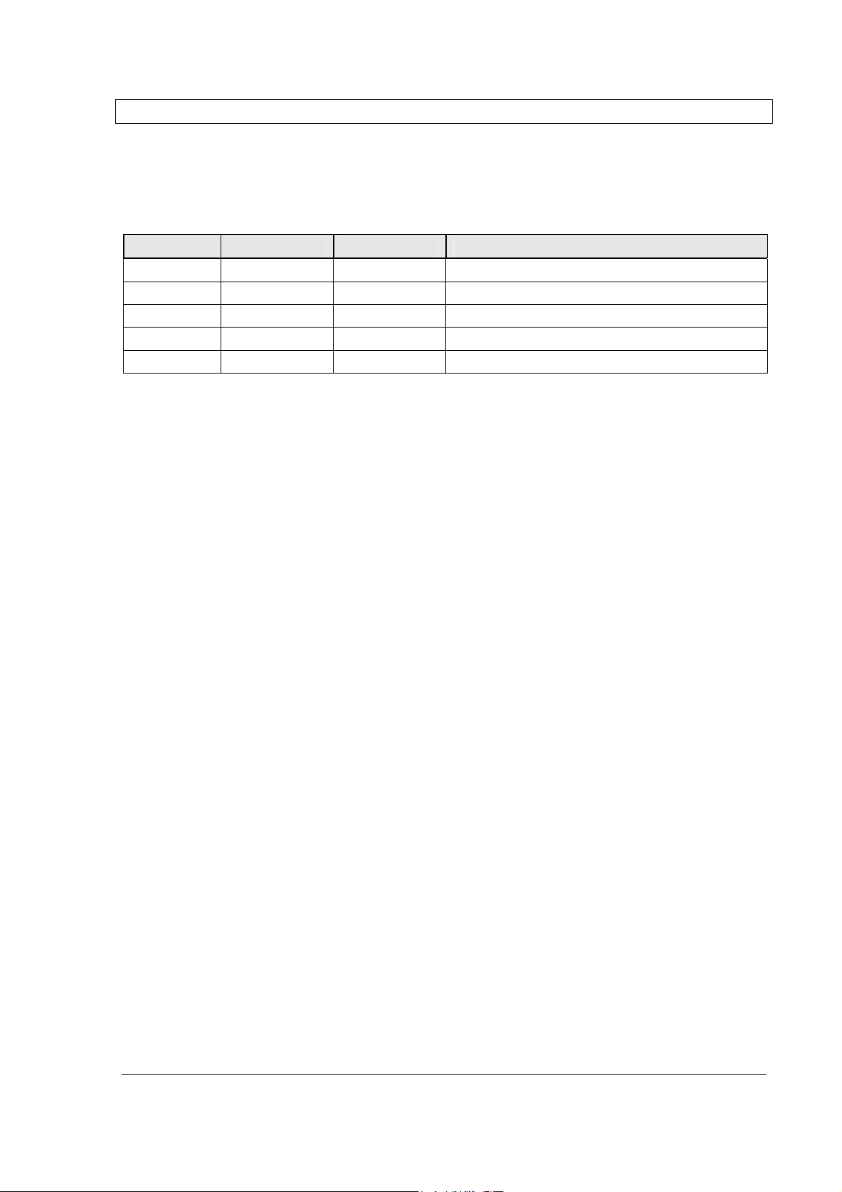
EVISION HISTORY
The revision history for this document is shown in Table 1.
Table 1: Revision history
P/N Revision Date Description
300TC80031
300TC80031
300TC80031
1.0 26-FEB-2008 Initial Version
1.3 13-May-2008 Frequency change, minor edits
1.4 27-May-2008 Minor edits from lab
1.5 28-May-2008 Minor edits – power per carrier
1.55 29-May-2008 Minor edits – Warning, Canada freq
3178B P
RODUCT MANUAL
Pub. 300TC80031 Rev. 1.55 Proprietary Data Page iii

P
RODUCT MANUAL
CONTENTS
CBDA D
EKO
3178B D
EKOLINK WIRELESS LTD
.
About This Manual ........................................................................................................... i
To Whom It Is Intended: ................................................................................................... i
Notice ................................................................................................................................ i
Disclaimer of Liability ...................................................................................................... i
Safety Warnings .............................................................................................................. ii
General Safety Warnings Concerning Use of This System ........................................... ii
Revision History ............................................................................................................. iii
1 INTRODUCTION .......................................................................................................... 6
1.1 Features ............................................................................................................... 6
1.2 Deko3178B Block Diagram Description ............................................................. 7
1.3 Deko3178B Interfaces ......................................................................................... 8
1.3.1 Front Panel Ports ................................................................................. 8
1.3.2 Front Panel Indicators .......................................................................... 8
1.3.3 Internal Power Selector ........................................................................ 9
1.3.3.1 UL Step Attenuator ......................................................................................10
1.3.3.2 DL Step Attenuator ......................................................................................10
2 Site and Installation Requirements ......................................................................... 11
2.1 Grounding Wires Requirements ....................................................................... 11
2.2 Antenna Requirements ..................................................................................... 11
2.2.1 Base (Donor) Antenna ....................................................................... 11
2.2.2 Mobile (Service) Antenna ................................................................... 11
2.3 Pre-Installation Safety Instructions .................................................................. 12
2.4 Installation Location, Environment and Cables ............................................... 12
3 Installing the Dual Band BDA .................................................................................. 13
3.1 Unpacking ......................................................................................................... 13
3.2 Required Tools and Materials ........................................................................... 13
3.3 Dry Contact Alarm Connections ....................................................................... 14
3.4 Grounding ......................................................................................................... 15
3.5 Power Up ........................................................................................................... 15
4 Antennas Installation and Connection .................................................................... 16
4.1 RF Gain Setting Criteria .................................................................................... 16
4.2 Antenna Installation .......................................................................................... 16
4.2.1 Base (Donor) Antenna ....................................................................... 16
4.2.2 Mobile (Service) Antenna ................................................................... 16
4.3 Antenna Connections ....................................................................................... 17
4.4 Verifying Isolation between Donor and Mobile Antennas ............................... 17
Page iv Proprietary Data Pub. 300TC80031 Rev. 1.55

D
EKOLINK WIRELESS LTD. COMPACT BI-DIRECTIONAL AMPLIFIER DEKO
3178B P
RODUCT MANUAL
4.5 Verifying the Link between the BTS and the Dual Band BDA .......................... 18
5 Monitoring and Alarms ............................................................................................. 19
5.1 Deko3178B Alarms ............................................................................................ 19
Appendices: ................................................................................................................... 20
Appendix A: Specifications (@+25°C) ..................................................................... 20
Electrical ........................................................................................................ 20
Mechanical Specifications .............................................................................. 20
Environmental Specifications .......................................................................... 20
Appendix B: Mechanical Drawing ............................................................................ 21
Appendix C: Dekolink Wireless Limited Warranty .................................................. 22
Pub. 300TC80031 Rev. 1.55 Proprietary Data Page v
P
RODUCT MANUAL
1111 INTRODUCTION
INTRODUCTION
INTRODUCTION INTRODUCTION
C
Deko3178B is a dual-band 700/800 MHz band selective mid-power amplifier in a single
compact unit.
Specially designed for public safety in-door networks, the Deko3178B small foot-print
and flexible installation options minimize interference with operations on the floor on
which it is installed.
It can be installed in a rack, mounted on a wall or on the ceiling. It’s relatively low
weight which allows mounting and maintenance by a single person, in addition to the
simple commissioning procedure that does not require a high level technician, provides
significant savings on labor costs.
The Deko3178B can be remotely monitored via an external wireless modem connected
to dry-contacts on the unit. It can be remotely accessed through a secure website or
through a third-party NMS via SNMP traps.
OMPACT REPEATER DEKO
3178B D
EKOLINK WIRELESS LTD
.
1.1 F
• Band selective, mid-power amplifier for public safety
• Dual-band SMR 700/800 MHz in a single unit
• Composite power (See Appendix A)
• 80 dB RF gain
• Small footprint and light weight for easy maintenance
• RF SAW filtering
• Gain matching uplink and downlink
• Alarm indication by LED and Dry contact
• Manual Gain Control
• High linear amplification
• Ideal for in-building and out-door coverage solutions
• Relative small size and light weight
• Cost effective solution
• Wall mounted easy Installation
• Reliable operation, maintenance free
EATURES
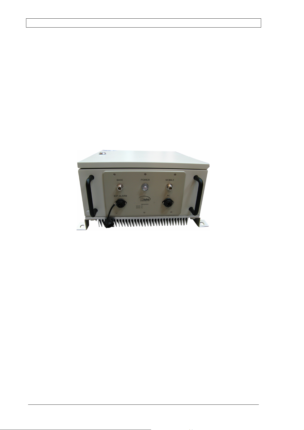
in-building network
Figure 1-1: Deko3178B Dual Band BDA
Page 6 Proprietary Data Pub. 300TC80031 Rev. 1.55

D
EKOLINK WIRELESS LTD. COMPACT BI-DIRECTIONAL AMPLIFIER DEKO
3178B P
RODUCT MANUAL
1.2 D
The CBDA Downlink path receives the RF signal from the base station, amplifies it and
transmits it to the subscriber. The BDA Uplink path receives the RF signal from the
subscriber amplifies it and transmits it to the base station. Two triplexers at the Dual
Band BDA’s input and output separate the uplink and downlink frequency bands,
creating high isolation between them and enabling the appropriate amplification of the
signals in each path.
Each path contains two amplifiers and an RF SAW Filter that provides signal filtration
and amplification. In addition, the Dual Band BDA power amplifiers have an ALC option
switch. When switched on, the ALC circuit limits the amplifier output power. The ALC
circuit senses the output power and introduces more attenuation, when the output
power exceeds the preset level. This way the gain of the amplifier is reduced, its output
power is limited and the intermediations products are kept below the desired level.
The gain of each path can be set manually. The separation of the gain setting
architecture enables setting the actual gain for each path.
EKO
3178B B
Warning: The AGC switch must be always ON in order to limit the spurious
signals.
LOCK DIAGRAM DESCRIPTION
Figure 2. Deko3178B Functional Block Diagram
Pub. 300TC80031 Rev. 1.55 Proprietary Data Page 7

P
Donor
antenna
Dry contact
alarm
connections
RODUCT MANUAL
C
OMPACT REPEATER DEKO
3178B D
EKOLINK WIRELESS LTD
.
1.3 D
EKO
3178B I
The Deko3178B interfaces are located on the dual band BDA top and front panel.
1.3.1 Front Panel Ports
The front panel includes the dual band antenna and power connections as shown
below.
There are two types of antenna connectors: Base (Donor) and Mobile (Service)
connections.
connections
NTERFACES
Service
antenna
connections
Unit AC
Power
connection
Figure 1-3. Deko3178B Front Panel
The following table provides a description of the front panel ports and connections.
Group Connectors
BASE Donor antenna connections.
MOBILE Service antenna connections.
EXT. Alarm Dry contact alarm port for external alert devices
AC Connection to AC power supply (100 to 240 VAC)
1.3.2 Front Panel Indicators
The front panel includes one Power indicator that shows green upon power up of the
unit.
Page 8 Proprietary Data Pub. 300TC80031 Rev. 1.55

D
Uplink step
attenuator
EKOLINK WIRELESS LTD. COMPACT BI-DIRECTIONAL AMPLIFIER DEKO
1.3.3 Internal Power Selector
Deko3178B includes two internal power level selectors used for manual UL and DL gain
control adjustment. See following figure.
3178B P
RODUCT MANUAL
Downlink step
attenuator
Figure 4. Internal View of Deko3178B UL/DL Step Attenuators
Pub. 300TC80031 Rev. 1.55 Proprietary Data Page 9

P
RODUCT MANUAL
C
1.3.3.1 UL Step Attenuator
The manual gain setting function for the UL path is performed with the use of a rotary
knob. The attenuation can be adjusted in 2 dB steps. See following figure.
OMPACT REPEATER DEKO
3178B D
EKOLINK WIRELESS LTD
.
1.3.3.2 DL Step Attenuator
The manual gain setting function for the DL path is performed with the use of a rotary
knob. The attenuation can be adjusted in 2 dB steps. See following figure.
Figure 5. UL Step Attenuator
Figure 6. DL Step Attenuator
Page 10 Proprietary Data Pub. 300TC80031 Rev. 1.55

D
EKOLINK WIRELESS LTD. COMPACT BI-DIRECTIONAL AMPLIFIER DEKO
2222 SITE AND INSTALLATIO
SITE AND INSTALLATION REQUIREMENTS
SITE AND INSTALLATIOSITE AND INSTALLATIO
This section describes the power, antenna and site requirements for the Dual Band BDA
installation.
N REQUIREMENTS
N REQUIREMENTSN REQUIREMENTS
3178B P
RODUCT MANUAL
2.1 G
2.2 A
ROUNDING WIRES REQUIREMENTS
Requirements for grounding wires
• Protective grounding conductor - should be aluminum with cross-section 10AWG.
• Lug of the protective grounding conductor - should be aluminum
• Washers and screw - should be high Cr stainless steel, or 12% Cr stainless steel, or
Cr on, Ni on steel, tin on steel
NTENNA REQUIREMENTS
2.2.1 Base (Donor) Antenna
The Base (Donor) antenna is usually installed outdoors and is either a directional
antenna such as a Yagi or a Panel antenna.
Donor Antenna specifications:
• Yagi type or similar – 10 to 15 dBi gain, very sharp beam pointed to the BTS.
• Cable and jumper loss is at least 2dB.
• The required Base signals should be the dominant signals; at least 6 dB higher
power than other signals.
• Example of antenna's typical specifications:
Gain: 8 dBd (=10 dBi)
VSWR: < 1:5:1
Impedance: 50 ohm
2.2.2 Mobile (Service) Antenna
The Mobile antenna is installed indoors.
Note: Before installing the Mobile antenna, see FCC regulations for information
regarding recommended distances between the antennas and populated areas.
The following describes the requirements for an omni-directional mobile used for indoor
applications.
Specifications:
• Omni directional antenna with a 0 to 2 dBi typical gain, or wide beam with up to
3dBi gain.
• Example of omni-directional antenna specifications:
Gain: 0 to 2 dBi
VSWR: < 2:1
Impedance: 50 ohm
Pub. 300TC80031 Rev. 1.55 Proprietary Data Page 11

P
RODUCT MANUAL
C
OMPACT REPEATER DEKO
3178B D
EKOLINK WIRELESS LTD
.
2.3 PRE-I
Before installing the Dual Band BDA, review the following safety information:
• Follow all local safety regulations when installing the Dual Band BDA.
• Only qualified personnel are authorized to install and maintain the Dual Band BDA.
• During normal operation, the Dual Band BDA door should be closed.
• Some maintenance tasks may require the Dual Band BDA door to be opened while
• Ground the CBDA with the grounding bolt located on the external lower side of the
• Do not use the grounding bolt to connect external devices.
• Follow Electro-Static Discharge (ESD) precautions.
• Before closing the CBDA cover, make sure no wires are in the way.
• Use low loss cables to connect the antennas to the Dual Band BDA.
2.4 I
T
HE DUAL BAND BDA MUST ALWAYS BE INSTALLED VERTICALLY AND TOP-DOWN, TO ALLOW
FREE-FLOW OF COOLING AIR. HORIZONTAL INSTALLATION ON A BENCH FOR LONG TIME MAY CAUSE
NSTALLATION SAFETY INSTRUCTIONS
the power is on. In such cases, perform the required tasks carefully and remember
to close the Dual Band BDA cover/door when finished.
cabinet (see 3.4).
NSTALLATION LOCATION, ENVIRONMENT AND CABLES
WARNING
DAMAGE TO THE DUAL BAND BDA DUE TO OVER-HEATING.
• Use a suitable mounting surface, such as a rigid wall.
• Follow Electro-Static Discharge (ESD) precautions.
• Install the Dual Band BDA close to the service area to monitor the output power and
noise figure.
• Use low loss cables to connect the antennas to the Dual Band BDA.
• Install the Dual Band BDA in a shielded, ventilated, and easy-to-reach area –
preferably at eye level.
Page 12 Proprietary Data Pub. 300TC80031 Rev. 1.55

D
EKOLINK WIRELESS LTD. COMPACT BI-DIRECTIONAL AMPLIFIER DEKO
3333 INSTALLING THE
INSTALLING THE DUAL BAND BDA
INSTALLING THE INSTALLING THE
DUAL BAND BDA
DUAL BAND BDADUAL BAND BDA
3178B P
RODUCT MANUAL
3.1 U
Upon receiving the Deko3178B unit, perform the following:
1. Examine the shipping container for damage before unpacking the unit.
2. Perform a visual inspection to reveal any physical damage to the
3. Verify that all of the equipment (listed below) is included. Otherwise
The Deko3178B Dual Band BDA is shipped with the following equipment:
3.2 R
A standard professional tool box is required in order to mount the Deko3178B Dual Band
BDA Mounting the Deko3178B
To mount the Dual Band BDA on the wall
1. Choose the location of the Dual Band BDA on the wall according to the following
2. Mark the drilling holes on the wall surface based on the Dual Band BDA four
NPACKING
equipment.
contact Dekolink Wireless Ltd.
• Deko3178B Dual Band BDA - Model: MW-CBDA-SMR700-800-16W80
• Key (used to lock the Dual Band BDA case)
• AC supply cable [6 ft.]
• User Manual (CD)
• Packaging box
EQUIRED TOOLS AND MATERIALS
criteria:
• The location should be at normal eye level height, above ground.
• Make sure that there is enough room to allow the door to swing completely
open, and to enable easy access to the Dual Band BDA for maintenance and onsite inspection.
mounting holes. See following figure.
Pub. 300TC80031 Rev. 1.55 Proprietary Data Page 13

P
Mounting hole
x 4
RODUCT MANUAL
C
OMPACT REPEATER DEKO
3178B D
EKOLINK WIRELESS LTD
.
3. Drill the four holes in the wall.
4. Align the chassis so that the mounting brackets fit into the holes drilled in the wall.
5. Use tire bolts, hex-head bolts, and M8 washers to secure the enclosure firmly to the
3.3 D
The front panel Alarm port (see 1.3.1) is an optional dry contact alarm port that
supports two alarm connections from external sources (incoming outputs). The use of
relay alarms (open or short wire-pair circuit) is recommended for the external alarms
port.
Figure 7. Deko3178B Mounting Holes
wall.
Note: Bolts and Washers are not supplied with the Dual Band BDA.
RY CONTACT ALARM CONNECTIONS
Page 14 Proprietary Data Pub. 300TC80031 Rev. 1.55
Figure 8. Alarm Connector Pinout

D
No. Pin Signal Name
EKOLINK WIRELESS LTD. COMPACT BI-DIRECTIONAL AMPLIFIER DEKO
The following table provides a description of the Alarm connector pinout and the
corresponding cable wire color-match pin.
1 A Not Connected
2 B Not Connected
3 C Dry Contact – Normally Closed
4 D Dry Contact - Normally Open
5 E Not Connected
6 F Not Connected
7 G Dry Contact - Common
• The relay alarms are
detecting a fault or when the power is cut off from the CBDA the relay alarms open.
• The relay alarms are connected to pins 3 and 4 of the front panel Alarms connector
used for remote sensing of faults.
Normally Open
, however they close upon power up. Upon
3178B P
RODUCT MANUAL
3.4 G
Once the Dual Band BDA is installed, you are required to ground it. The Dual Band BDA
case includes a grounding lug, where a grounding conductor cable should be attached.
The Dual Band BDA grounding conductor is found at the right-hand side of the bottom
panel.
The protective grounding conductor should be copper with cross-section of 10AWG. The
lug of the protective conductor should also be aluminum. Washers and screw should be
high CR stainless steel, or 12% stainless steel, or 12% Cr stainless steel, or Cr on steel,
Ni on steel, tin on steel.
3.5 P
To power-up
The Dual Band BDA operates from a 100/240 VAC Mains. The maximum consumption
power is 105W.
Connect the AC power cable to the Dual Band BDA front panel AC IN (100-240VAC)
connector.
ROUNDING
OWER UP
100-240VAC
Figure 9.Power Up Connection
Pub. 300TC80031 Rev. 1.55 Proprietary Data Page 15

P
RODUCT MANUAL
4444 ANTENNAS INSTALLATIO
ANTENNAS INSTALLATION AND
ANTENNAS INSTALLATIOANTENNAS INSTALLATIO
C
CONNECTION
CONNECTION
CONNECTIONCONNECTION
OMPACT REPEATER DEKO
3178B D
N AND
N AND N AND
EKOLINK WIRELESS LTD
.
4.1 RF G
In order for the CBDA Dual Band BDA to operate effectively the isolation between the
base station and the mobile antenna must be
The step attenuator on the low noise amplifier can reduce the CBDA gain. The CBDA
gain can be reduced by the amount indicated on the step attenuator.
Note: A higher CBDA gain than the isolation between the antennas would cause
oscillation which would saturate the amplifier. On the other hand, if the isolation were
only a few db higher than the CBDA gain, it would not be enough to cause oscillation
however it would cause gain ripple in the band.
4.2 A
AIN SETTING CRITERIA
NTENNA INSTALLATION
4.2.1 Base (Donor) Antenna
NOTE: Verify that the antennas meet requirements described in section 2.2.1.
Installation requirements:
• The antenna should point to the direction of the base station for maximum input
power
• Verify that the antenna is in the base stations line of sight (raise the antenna if
necessary)
• Install the donor antenna at a higher level (i.e. floor) than the mobile antenna
• Must be installed at a minimum distance of 1 meter from any personnel within the
area.
at least 15 db higher than the CBDA gain
.
4.2.2 Mobile (Service) Antenna
NOTE: Verify that the antennas meet requirements described in section 2.2.2.
Installation requirements:
• Install the service antenna on the ceiling or on the wall so it would shadow the
required coverage area within the in building environment.
• Installation of this antenna must provide a minimum separation distance of 0.5 m
from any personnel within the area.
• Cable and jumper loss is at least 2dB.
Page 16 Proprietary Data Pub. 300TC80031 Rev. 1.55

D
EKOLINK WIRELESS LTD. COMPACT BI-DIRECTIONAL AMPLIFIER DEKO
3178B P
RODUCT MANUAL
4.3 A
Note 1: Do not operate the Dual Band BDA without terminating the antenna connections
with actual antennas or proper dummy loads.
Note 2: If the coaxial cables are NOT weather-resistant type, wrap the exterior coaxial
cables with insulation and holding tape (Type 3M Rubber splicing tape) for
environmental protection and to ensure longer lifetime.
To connect the antennas to the Dual Band BDA
• Connect the Donor antenna to the Dual Band BDA BASE port.
• Connect the Service antenna to the Dual Band BDA MOBILE port.
NTENNA CONNECTIONS
4.4 V
The isolation between the Base/Donor and Mobile/Service antennas is critical especially
for high gain, outdoor applications.
For proper operation of the Deko3178B Dual Band BDA, it is recommended that the
isolation between the Donor and Service antennas be at least 15 dB higher than the
Dual Band BDA set gain.
The isolation between the antennas is critical for high gain outdoor Dual Band BDA.
To measure the isolation; inject a known signal into one antenna and measure the
power at the other antenna. This should be done across the frequency range of both
uplink and downlink bands.
NOTE: Lower isolation can lead to high in-band ripple, oscillations and low signal quality.
To measure the isolation, proceed as follows:
1. Inject a known signal from a signal generator into one antenna (preferably the
Figure 4-1.Deko3178B – Antenna Connections
ERIFYING ISOLATION BETWEEN DONOR AND MOBILE ANTENNAS
Donor antenna).
Pub. 300TC80031 Rev. 1.55 Proprietary Data Page 17

P
RODUCT MANUAL
C
2. Measure the coupled output from the Service antenna, using the Spectrum analyzer
and LNA if applicable.
3. Perform this procedure across the frequency range of both the Uplink and Downlink
bands.
4. Register the lower result for system operation.
NOTE: The SALC feature overcomes this procedure.
OMPACT REPEATER DEKO
3178B D
EKOLINK WIRELESS LTD
.
4.5 V
This test checks the signal strength from the BTS antenna to the CBDA Dual Band BDA.
Proceed as follows:
1. Using a Spectrum analyzer, measure the received signal from BTS at the Donor
2. Adjust the Donor antenna direction to receive the maximum signal strength.
3. Compare the received signal strength with the calculated signal strength from the
ERIFYING THE LINK BETWEEN THE
antenna port near the Dual Band BDA.
design phase.
In case of discrepancy, check for one of the following:
• Antenna out of direction
• Antenna tuned to side lobe instead of main lobe
• Antenna connector or antenna cable faulty
• Line of sight problem (obstruction), etc.
• Register the signal strength of the downlink channel for the system operation
phase.
BTS
AND THE DUAL BAND
BDA
Page 18 Proprietary Data Pub. 300TC80031 Rev. 1.55

D
EKOLINK WIRELESS LTD. COMPACT BI-DIRECTIONAL AMPLIFIER DEKO
5555 MONITORING AND ALARM
MONITORING AND ALARMSSSS
MONITORING AND ALARMMONITORING AND ALARM
3178B P
RODUCT MANUAL
5.1 D
EKO
3178B A
The Deko3178B Dual Band BDA has two main active elements: DL Power Amplifier and
UL power amplifier. A monitor circuit monitors these elements and initiates an alarm
upon detecting a deviation from the normal operation. The summarized alarm output of
the monitoring card is sent to the corresponding front panel Alarm connector.
The monitor circuit performs the following functions:
• Monitors the current of uplink power amplifier - If the current is either below or
above the specified limits an automatic alarm function is provided through a lit LED
and a dry contacts relay.
• Monitors the downlink RF output power - If the output power is lower than +20dBm
an alarm function is provided by a lit LED and a dry contacts relay.
LARMS
Indication Cause Action
Downlink LED is
ON
Downlink LED is
ON
Uplink Amp LED is
ON
Indicates low RF power at
downlink path <20 dBm)
BDA fault Replace BDA
Uplink amplifier over current
or undercurrent fault
Check base antenna connection
Check antenna alignment to base.
Use higher gain BDA
Replace BDA
Pub. 300TC80031 Rev. 1.55 Proprietary Data Page 19

P
RODUCT MANUAL
APPENDI
APPENDICES:
APPENDIAPPENDI
A
PPENDIX A: SPECIFICATIONS
Parameters DL UL
Frequency Range
Passband Gain 80 dB
Passband Ripple ± 1.5 dB
Gain Attenuation Range (in 2 dB steps) 0 to 30 dB
Max output power
Per carrier
Output IP3 (typical) + 50 dBm + 43 dBm
Noise Figure@ Maximum Gain (typical) 5 dB
Propagation Delay < 5 µsec
Max RF Input Power (no damage) 10 dBm
Max RF Input Power
Per carrier @ Max Gain
C
CES:
CES:CES:
This paragraph provides the electrical, mechanical and environmental specifications of
the Deko3178B Dual Band BDA.
USA 769 - 775 MHz
Canada 759-780 MHz
OMPACT REPEATER DEKO
Single carrier 31.8 dBm 23.3 dBm
Multiple carriers 26 dBm 20 dBm
Single carrier -49dBm -57dBm
Multiple carriers -56dBm -60dBm
3178B D
(@+25°C)
851 – 869 MHz
847-872 MHz
EKOLINK WIRELESS LTD
799 - 805 MHz
806 - 824 MHz
790-828 MHz
.
Electrical
Parameter Value
Power Supply 100/240 VAC, 105 W
Impedance Level 50 Ω
RF Connector N-type, female
Diplexer’s Connectors SMA-type, female
VSWR (typical) 1.5 : 1
Mechanical Specifications
Parameter Value
Size L x W x H 400 x 400 x 220 mm (approx.) [15.76 x 15.76 x 8.66
inch]
Weight 14 kg (approx.) (30.8 lbs)
Weatherproof IP-65, NEMA 4
Environmental Specifications
Deko3178B is designed to operate properly under the following environmental conditions.
Condition Value
Operating temperature
Storage temperature
-10 °C to +50 °C (14 to 122° F)
-40 °C to +80 °C (-40 to 176° F)
Page 20 Proprietary Data Pub. 300TC80031 Rev. 1.55

D
EKOLINK WIRELESS LTD. COMPACT BI-DIRECTIONAL AMPLIFIER DEKO
A
PPENDIX B: MECHANICAL DRAWING
The following mechanical drawing shows the Deko3178B dimensions.
3178B P
RODUCT MANUAL
Pub. 300TC80031 Rev. 1.55 Proprietary Data Page 21

P
RODUCT MANUAL
A
PPENDIX C: DEKOLINK WIRELESS LIMITED WARRANTY
Dekolink Wireless [Ltd.] (“Dekolink”), manufacturer of this product (the “Product”) warrants to the
original purchaser (“Purchaser”) that the Product is free from defects in materials and workmanship
for a term that ends on the earlier of twelve (12) months from the date of activation of the Product
or fifteen (15) months from the date of shipment of the Product by Dekolink. The obligations of
Dekolink under this warranty shall be limited solely to the repair or exchange or giving credit for, at
the option of Dekolink, any Product that may prove defective in accordance with evidence
satisfactory to Dekolink. Any repair or replacement of the Product by Dekolink shall not extend the
original warranty period. This warranty is exclusive to the original Purchaser and is not assignable.
This warranty applies only upon the condition that the Product has been installed, maintained and
operated under conditions of normal use. The provisions of this warranty shall not apply if, in
Dekolink judgment, the Product has been subject to misuse or neglect, damaged in an accident or by
act of vandalism, or repaired or altered in any way that adversely affects its performance or
reliability.
To obtain warranty service, Purchaser may, upon the prior written authorization of Dekolink or its
authorized service representative, return the defective Product to Dekolink authorized service center.
All shipping and insurance charges are the sole responsibility of Purchaser and are not included in
this warranty.
Dekolink expressly excludes and disclaims all other warranties, including but not limited to any
warranties of merchantability or fitness for a particular purpose.
Dekolink shall in no event be liable for any special, indirect, incidental, consequential or punitive
damages or for loss, damage, or expense, including loss of use, profits, revenue, or goodwill, directly
or indirectly arising from purchaser’s use or inability to use the merchandise, or for loss or
destruction of other property or from any other cause, even if Dekolink has been advised of the
possibility of such damage. Some states do not allow the exclusion or limitation of incidental or
consequential damages so these limitations may not apply under certain circumstances.
The liability of Dekolink shall in no event exceed an amount equivalent to the purchase price paid by
the purchaser for the defective product.
This warranty shall not be extended, altered or varied except by a written instrument duly signed by
Dekolink.
C
OMPACT REPEATER DEKO
3178B D
EKOLINK WIRELESS LTD
.
Page 22 Proprietary Data Pub. 300TC80031 Rev. 1.55
 Loading...