

Page 1

Dekolink WIRELESS Ltd.
16 Bazel St. Qiryat-Arieh Petah-Tikva, Israel, 49510
Tel- 972-3-9180-180 Fax-972-3- 190-9180
e-mail: marketing@dekolink.com
web www.dekolink.com
INSTALLATION
AND
OPERATING INSTRUCTIONS
FOR
HIGH POWER PCS REPEATER
MODEL: MW-BDA-PCS-X-50W90
Dekolink Wireless Proprietary and Confidential Information. Copying, Distribution, and Disclosure are
prohibited without Express Authorization from Dekolink Wireless Company.
50W 1 of 16 rev 1 10/03 Page
This document is protected by all applicable copyright laws.
Page 2

Table of contents
1.
Repeater overview
Dekolink WIRELESS Ltd.
16 Bazel St. Qiryat-Arieh Petah-Tikva, Israel, 49510
Tel- 972-3-9180-180 Fax-972-3- 190-9180
e-mail: marketing@dekolink.com
web www.dekolink.com
___________________________________________________ 3
Block diagram description
2.
2.1.
Step attenuator and RF gain setting ______________________________________________ 5
2.2.
Automatic Level (gain) Control (ALC) functionality__________________________________ 5
2.3.
Power supply unit____________________________________________________________ 5
Power control unit
2.4.
Repeater connection module
2.5.
Remote monitoring and control module
2.6.
3.
4.
4.1.
4.2.
4.3.
5.
5.1.
5.2.
5.3.
Repeater operation
Repeater monitoring and control
Controls 8
Link alarm status (downlink & uplink)____________________________________________ 8
General alarm status _________________________________________________________ 8
Donor side antenna installation
Service side antenna Installation
Antenna isolation
Repeater installation
___________________________________________________________ 5
___________________________________________________________ 10
_____________________________________________________ 3
____________________________________________________ 6
___________________________________________ 6
__________________________________________________ 7
_________________________________________ 8
________________________________________________ 10
________________________________________________ 10
________________________________________________ 10
Installation steps
5.4.
6.
6.1.
6.2.
6.3.
Mechanical layout
Mechanical outline
7.
8.
Applicable documents
Repeater Management Application Software User Manual
50W rev 1 10/03 Page 2 of 16
Specifications
Electrical specifications
Mechanical specifications
Environmental conditions
____________________________________________________________ 13
RF exposure warning
Limited warranty
____________________________________________________________ 11
_____________________________________________________ 12
______________________________________________________ 12
_____________________________________________________ 12
_____________________________________________________ 13
___________________________________________________________ 14
________________________________________________ 15
___________________________________________________ 16
Page 3

Dekolink WIRELESS Ltd.
16 Bazel St. Qiryat-Arieh Petah-Tikva, Israel, 49510
Tel- 972-3-9180-180 Fax-972-3- 190-9180
e-mail: marketing@dekolink.com
web www.dekolink.com
1. Repeater overview
Dekolink’s repeater assembly provides an exceptional capability to extend the coverage
area of radio communications into building areas and RF shielded environments.
The unit’s integrated high linearity power amplifiers contribute to the overall improved
system performance while avoiding non-linear related phenomena. The unit is based on a
duplexed path configuration, having sharp out of band attenuation for improved isolation
between the receiving and transmitting paths.
2. Block diagram description
Within the repeater, the downlink path receives RF signals from base station (donor side)
amplifies them and re-transmits them to the subscribers (service area). The repeater
uplink path receives RF signals from the service side, amplifies them and retransmits
them towards the donating base station. On both the repeaters’ ends, cavity tuned
duplexers separate the Tx and Rx signals (frequency separation) and diverts them to the
amplifying path while providing the required signal isolation.
Two amplifiers are used to perform the required amplification for each of the paths; a Low
Noise Amplifier (LNA) and a high power amplifier. Each of the LNAs includes an internal
step attenuator that allows adjusting the gain of the relevant path to the required level
depending on the specific field situation.
50W rev 1 10/03 Page 3 of 16
Page 4

Dekolink WIRELESS Ltd.
16 Bazel St. Qiryat-Arieh Petah-Tikva, Israel, 49510
Tel- 972-3-9180-180 Fax-972-3- 190-9180
e-mail: marketing@dekolink.com
web www.dekolink.com
TO
BASE
Figure 1 - Repeater RF block diagram
Downlink
Coupler
Uplink
Attenuator
Duplexer
LNA
Attenuator
Power
Monitor
Power
Amplifier
Power
Amplifier
Attenuator
Power
Monitor
ALC
TO
MOBILE
Duplexer
LNA
CONTROLS
& CONTROL
MONITOR
MODULE
ALARMS
ALARMS
ALC
CONNECTION
MODULE
+28
VDC
AC/DC
POWER
SUPPLY
POWER ON
LED
AC
IN
50W rev 1 10/03 Page 4 of 16
Page 5

Dekolink WIRELESS Ltd.
16 Bazel St. Qiryat-Arieh Petah-Tikva, Israel, 49510
Tel- 972-3-9180-180 Fax-972-3- 190-9180
e-mail: marketing@dekolink.com
web www.dekolink.com
2.1. Step attenuator and RF gain setting
For proper operation and in order to avoid oscillations, Dekolink’s suggestion is to have
an isolation value between the base station antenna (donor side) and the mobile antenna
(service side) that exceeds the repeaters’ set gain by 12dB.
A step attenuator integrated in the LNA can be adjusted to change the repeaters’ gain in
1dB steps, within a range of 31dB. Adjustment is done via SW.
2.2. Automatic Level (gain) Control (ALC) functionality
In order to prevent saturation of the power amplifiers, the repeater is equipped with ALC
circuits on both its paths. When a high signal is received, the ALC detects its amplitude
and sends a feedback signal to a voltage variable attenuator, which attenuates the signal
level so that the output power of the amplifier does not exceed a preset limit.
The uplink ALC is always on.
The ALC function on the downlink path can be enabled/disabled via SW. If the ALC on the
downlink path is disabled then the amplifier gives maximum gain.
2.3. Power supply unit
The repeater includes a high efficiency power supply unit able to supply the required
power needed to run it.
This module converts the supplied mains voltage, to +28VDC.
2.4. Power control unit
The power from the +28VDC power supply unit is connected to this module.
This connection unit contains:
Power On/Off switch (28VDC)
DC fuse
50W rev 1 10/03 Page 5 of 16
Page 6
Dekolink WIRELESS Ltd.
16 Bazel St. Qiryat-Arieh Petah-Tikva, Israel, 49510
Tel- 972-3-9180-180 Fax-972-3- 190-9180
e-mail: marketing@dekolink.com
web www.dekolink.com
2.5. Repeater connection module
The connection module supplies and monitors the DC power to all the active components
of the repeater.
The repeater values are sampled here and, if needed, the relevant alarms are sent to the
remote monitoring and control. Module
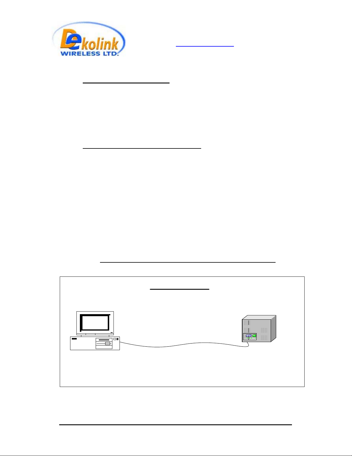
2.6. Remote monitoring and control module
The remote monitoring and control module is based on a dedicated microcontroller. The
interface to this controller is via a serial RS-232C port.
There are two ways for monitoring and control of the repeater as follows:
Local Mode: Through a local serial computer connection
The host computer has dedicated software, for analysis, control and display of the status
of the repeater using a friendly Graphics User Interface (GUI).
For repeater control software installation see “Repeater Management Application
Software User Manual”.
Figure 2 - Repeater Monitoring and Control setup
Local Mode
PC / Laptop
COM1
BDA Repeater
50W rev 1 10/03 Page 6 of 16
Page 7

Dekolink WIRELESS Ltd.
16 Bazel St. Qiryat-Arieh Petah-Tikva, Israel, 49510
Tel- 972-3-9180-180 Fax-972-3- 190-9180
e-mail: marketing@dekolink.com
web www.dekolink.com
3.
Repeater operation
The repeater AC power is supplied through a 3-wire male plug connector. A switch on the
power control unit turns on the repeater.
The RF connection is made via 2 type “N” connectors. The repeater connector labeled
“BASE” must be connected to the roof antenna pointing to the base station (donor side).
The repeater connector labeled “MOBILE” must be connected to the antenna/s pointing to
the area covered by the repeater (service side).
Figure 3 – AC connector pin assignment
The repeater can be remotely controlled and monitored via a modem connected to the
repeaters’ remote monitoring and control module. The modem uses a directional coupler
to transmit and receive RF signals through the repeater base side antenna.
The repeater can be controlled locally through RS232 connector housed on the remote
monitoring and control unit. This is a D9 male connector; pin 2 is Tx; pin 3 is Rx and pin 5
is Gnd.
The power on/off switch is housed on the power control unit.
50W rev 1 10/03 Page 7 of 16
Page 8

Dekolink WIRELESS Ltd.
16 Bazel St. Qiryat-Arieh Petah-Tikva, Israel, 49510
Tel- 972-3-9180-180 Fax-972-3- 190-9180
e-mail: marketing@dekolink.com
web www.dekolink.com
4. Repeater monitoring and control
4.1. Controls
4.1.1. PAmp On: Turns on/off the downlink power amplifier (√ indicates amplifier is
on)
4.1.2. Max Power:
indicates DL ALC is on)
4.1.3. Max Gain:
4.1.4. FWD Threshold:
declaration. For example if the value shows 33dBm and the repeater transmits
less than 33dBm (downlink), the FWD Measure alarm (that appears in the Link
Alarm Status) will turn red. The actual transmitted power is also shown.
4.2. Link alarm status (downlink & uplink)
4.2.1. Power Amplifier: Turns red when the Power Amplifier (PA) current is above
This window is blank when the downlink ALC is turned off (
The repeater gain is selected from a choice list
This value sets the lower limit for a downlink power alarm
√
or below its specified limits
4.2.2. Main Voltage:
above its limits
4.2.3. Pre Amplifier:
above or below its specified limits
4.2.4. VSWR:
Turns red when the return loss of the downlink antenna or cable
connection exceeds 10dB (=VSWR 2:1)
4.2.5. FWD Measure:
4.3. General alarm status
4.3.1. Temperature: Turns red when the chassis temperature exceeds 80°C
4.3.2. Door Open: Turns red when the repeater’s door is opened
4.3.3. FAN Failure:
specified limits
Turns red when the internal power supply voltage is below or
Turns red when the Low Noise Amplifier (LNA) current is
see FWD Threshold above
Turns red when the internal FAN current is above or below its
50W rev 1 10/03 Page 8 of 16
Page 9

Dekolink WIRELESS Ltd.
16 Bazel St. Qiryat-Arieh Petah-Tikva, Israel, 49510
Tel- 972-3-9180-180 Fax-972-3- 190-9180
e-mail: marketing@dekolink.com
web www.dekolink.com
Figure 4 – Repeater monitoring and control screen
50W rev 1 10/03 Page 9 of 16
Page 10

Dekolink WIRELESS Ltd.
16 Bazel St. Qiryat-Arieh Petah-Tikva, Israel, 49510
Tel- 972-3-9180-180 Fax-972-3- 190-9180
e-mail: marketing@dekolink.com
web www.dekolink.com
5. Repeater installation
Install the repeater in a shielded, ventilated and easy to reach area. Use low loss cables to
connect antennas to the repeater. Install the repeater close to the service area to improve
output power and noise figure.
The repeater’s “BASE” connector port is connected to donor antenna (usually a Yagi
antenna), while the repeater’s “MOBILE” connector port is connected to a mobile antenna or
Distributed Antenna System – DAS (outdoor or indoor).
5.1. Donor side antenna installation
Typically this is a directional antenna such as a Yagi or Dish antenna of 10 to 15dB gain. This
antenna points to the base station in order to get maximum input power. It should be installed
in “line of sight” with the base site. If no line of sight is achieved it is recommended to raise
the antenna higher until the line of sight is reached. The signals received from the base
station that are to be retransmitted should be the dominant (at least 6dB higher than other
received signals in the vicinity).
Attention to the minimal antenna isolation needed should be carefully considered. Choose the
antenna site to get the maximum isolation from the remote (mobile serving) antenna.
5.2. Service side antenna Installation
For outdoor applications the remote antenna is a directional antenna depending on the
coverage requirements.
For indoor applications covering a large building, the RF signals are usually split using power
dividers and distributed antenna systems, each covering a floor or a smaller area.
5.3. Antenna isolation
For proper operation the isolation between the donor side and service side antennas must be
at least 12dB higher than the repeater’s gain. Lower isolation leads to high in-band ripple and
noise. Oscillations appear when the isolation is lower than repeater set gain.
To measure the isolation; inject a known signal into one antenna and measure the power at
the other antenna. This should be done across the frequency range of both uplink and
downlink bands.
50W rev 1 10/03 Page 10 of 16
Page 11

Dekolink WIRELESS Ltd.
16 Bazel St. Qiryat-Arieh Petah-Tikva, Israel, 49510
Tel- 972-3-9180-180 Fax-972-3- 190-9180
e-mail: marketing@dekolink.com
web www.dekolink.com
5.4. Installation steps
5.4.1. Install all antennas. Measure the isolation between the two antennas. The
isolation limits the maximum gain for the repeater. For a 90dB gain; an isolation
of over 102 dB is required. Lower isolation will increase noise. Isolation lower
than or equal to repeater gain would start oscillations within the repeater.
5.4.2. Measure the channel power reaching the base input of the repeater. This
sets the recommended repeater gain. For example; 4 signals are received at –
49dBm each (total power of –43dBm). Since the maximum composite power of
the repeater is +40dBm, the gain setting should be over 40+43 = 83dB in order
to get maximum power from the repeater. In this case isolation of over 95dB is
necessary for proper operation.
5.4.3. Connect the antenna cables to the repeater ports.
5.4.4. Turn on the downlink ALC (the ALC is always on at the uplink preamplifier).
This ALC limits the output power of the repeater. The ALC at the downlink path
guarantees constant downlink power when and if the donor power changes.
5.4.5. Set repeater gain to the calculated value (as in par. 2 above) using the SW
package. Turn on the RF power amplifier.
5.4.6. Set the uplink channel gain as required (usually the same gain as in the
downlink path is used).
5.4.7. Note the measured FWD Power indicating proper functionality of the
repeater.
WARNING
: Do not set the repeater RF gain higher than 12 dB below the measured antenna
isolation.
WARNING:
Check that the LED on the uplink power amplifier indicating uplink composite
power does not lit permanently. This LED would light permanently if the isolation between
antennas is low (indicating oscillation) or the repeater is faulty. During normal operation this
LED may flicker if a nearby mobile is in use.
50W rev 1 10/03 Page 11 of 16
Page 12

Dekolink WIRELESS Ltd.
16 Bazel St. Qiryat-Arieh Petah-Tikva, Israel, 49510
Tel- 972-3-9180-180 Fax-972-3- 190-9180
e-mail: marketing@dekolink.com
web www.dekolink.com
6. Specifications
6.1. Electrical specifications
Specification Parameter
Downlink Uplink
Frequency Range [MHz]
Gain [dB]
Passband ripple <3dB p-p
Attenuation range (via |SW)
Noise figure ≤ 5dB
Output power @ 1dB compression 50W 8W
3rd order intercept point 62 dBm min 47 dBm typ.
Composite power output +40dBm
Downlink IMD @ two tone 37dBm each 50dBc -------------------Uplink IMD @ two tone
24dBm each
ALC factory set level (nom.) 40dBm 27dBm
ALC range 15dB 20dB
Impedance
VSWR <1.5:1
Rx/Tx isolation > 100dB
Power supply AC 110/220V/50Hz Range: 176~264V, 45~65
System frequency range
See table below See table below
90±4
0 to 31dB in 1dB steps
+27dBm
------------------- 44dBc
50Ω
BLOCK
A
D
B
E
F
C
AD
BE
DBE
EFC
Model No. Down Link
MW-BDA-PCS-A-50W90 1930-1945
MW-BDA-PCS-D-50W90 1945-1950
MW-BDA-PCS-B-50W90 1950-1965
MW-BDA-PCS-E-50W90 1965-1970
MW-BDA-PCS-F-50W90 1970-1975
MW-BDA-PCS-C-50W90 1970-1975
MW-BDA-PCS-AD-50W90 1930-1950
MW-BDA-PCS-BE-50W90 1950-1970
MW-BDA-PCS-DBE-50W90 1945-1970
MW-BDA-PCS-EFC-50W90 1965-1990
Up Link
1850-1865
1865-1870
1870-1885
1885-1890
1890-1895
1895-1910
1850-1870
1870-1890
1865-1890
1885-1910
6.2. Mechanical specifications
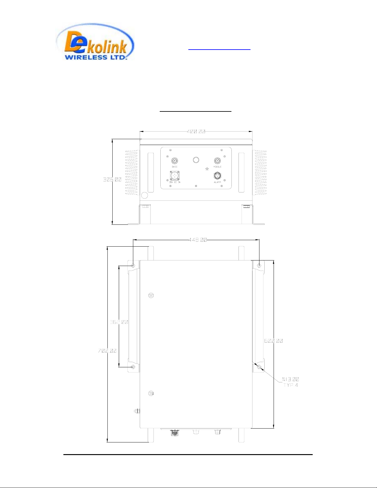
Size [mm] 600X400X300 (approx.)
RF connectors N-type Female
Weight [Kg] 40 (approx.)
Enclosure Type Weatherproof enclosure for wall-mounted
installation
50W rev 1 10/03 Page 12 of 16
Page 13

Dekolink WIRELESS Ltd.
16 Bazel St. Qiryat-Arieh Petah-Tikva, Israel, 49510
Tel- 972-3-9180-180 Fax-972-3- 190-9180
e-mail: marketing@dekolink.com
6.3. Environmental conditions
Operating temperature
-30
°
°
C to +50°C Humidity ≤ 95% Weatherproof conditions Protected to IP65
web www.dekolink.com
Uplink Power
Amplifier
Downlink Power
Amplifier
Repeater
Connection
Module
Mechanical layout
Repeater Monitoring
and Control Unit
RS 232 Port for
Power
Control Unit
Repeater Control
50W rev 1 10/03 Page 13 of 16
Page 14
Dekolink WIRELESS Ltd.
16 Bazel St. Qiryat-Arieh Petah-Tikva, Israel, 49510
Tel- 972-3-9180-180 Fax-972-3- 190-9180
e-mail: marketing@dekolink.com
web www.dekolink.com
Mechanical outline
50W rev 1 10/03 Page 14 of 16
Page 15

Dekolink WIRELESS Ltd.
16 Bazel St. Qiryat-Arieh Petah-Tikva, Israel, 49510
Tel- 972-3-9180-180 Fax-972-3- 190-9180
e-mail: marketing@dekolink.com
web www.dekolink.com
7. RF exposure warning
In order to satisfy the FCC RF exposure requirements, you must ensure that the installation
complies with the following:
One antenna is connected via cable that has typical 1~10 dB attenuation (depends on the
length of the cable) to the BDA base port. This antenna is installed outdoor and has very
sharp beam (Yagi type or similar) pointed to the donor (BTS). This type of antenna has about
10 dBi gain. Typical specifications: gain: 8 dBd (=10.1 dBi), VSWR: better than 1.5:1 ,
Impedance: 50 ohm. The outdoor antenna must be installed to provide a minimum separation
distance of 1 m (100 cm) from persons within the area.
The second antenna is connected to the BDA MOBILE port. There are two applications:
Outdoor and Indoor.
In the case of Outdoor the type of antenna is omnidirectional (isotropic) with 0 to 2 dBi typical
gain, or wide beam with up to 8 dBi gain, and is installed on a mast to cover shadowed,
outdoor, area. This antenna must be installed to provide a minimum separation distance of 2
m (200 cm) from persons within the area
In the case of Indoor coverage the power is split to several, omnidirectional (isotropic)
antenna with 0 to 2 dBi typical gain, and distributes to different indoor areas (in building
floors, tunnels, basements, parking lots, shopping centers etc.). Typical specifications: gain: 2
dBi, VSWR: better than 2:1 , Impedance: 50 ohm. At least 5 such antenna must be connected
to the BDA using cables and splitters. In this case the max. EIRP from each antenna will not
exceed 3W so that the minimum required separation distance from persons within the area is
20cm.
Less separation is needed if the power is divided into more than 5 antenna covering many
floors or areas.
50W rev 1 10/03 Page 15 of 16
Page 16

Dekolink WIRELESS Ltd.
16 Bazel St. Qiryat-Arieh Petah-Tikva, Israel, 49510
Tel- 972-3-9180-180 Fax-972-3- 190-9180
e-mail: marketing@dekolink.com
web www.dekolink.com
8. Limited warranty
Dekolink Wireless [Ltd.] (“Dekolink”), manufacturer of this product (the “Product”) warrants to
the original purchaser (“Purchaser”) that the Product is free from defects in materials and
workmanship for a term that ends on the earlier of twelve (12) months from the date of
activation of the Product or fifteen (15) months from the date of shipment of the Product by
Dekolink. The obligations of Dekolink under this warranty shall be limited solely to the repair
or exchange or giving credit for, at the option of Dekolink, any Product that may prove
defective in accordance with evidence satisfactory to Dekolink. Any repair or replacement of
the Product by Dekolink shall not extend the original warranty period. This warranty is
exclusive to the original Purchaser and is not assignable.
This warranty applies only upon the condition that the Product has been installed, maintained
and operated under conditions of normal use. The provisions of this warranty shall not apply
if, in Dekolink’s judgment, the Product has been subject to misuse or neglect, damaged in an
accident or by act of vandalism, or repaired or altered in any way that adversely affects its
performance or reliability.
To obtain warranty service, Purchaser may, upon the prior written authorization of Dekolink or
its authorized service representative, return the defective Product to Dekolink’s authorized
service center. All shipping and insurance charges are the sole responsibility of Purchaser
and are not included in this warranty.
Dekolink expressly excludes and disclaims all other warranties, including but not limited to
any warranties of merchantability or fitness for a particular purpose.
Dekolink shall in no event be liable for any special, indirect, incidental, consequential or
punitive damages or for loss, damage, or expense, including loss of use, profits, revenue, or
goodwill, directly or indirectly arising from purchaser’s use or inability to use the merchandise,
or for loss or destruction of other property or from any other cause, even if Dekolink has been
advised of the possibility of such damage. Some states do not allow the exclusion or
limitation of incidental or consequential damages so these limitations may not apply under
certain circumstances.
The liability of Dekolink shall in no event exceed an amount equivalent to the purchase price
paid by the purchaser for the defective product.
This warranty shall not be extended, altered or varied except by a written instrument duly
signed by Dekolink.
50W rev 1 10/03 Page 16 of 16
 Loading...