

Page 1
Dekolink WIRELESS Ltd.
16 Bazel St. Qiryat-Arieh Petah-Tikva, Israel, 49510
Tel- 972-3-9180-180 Fax-972-3- -
e-mail: marketing@decolink.com web www.decolink.com
INSTALLATION
AND
OPERATING INSTRUCTIONS
FOR
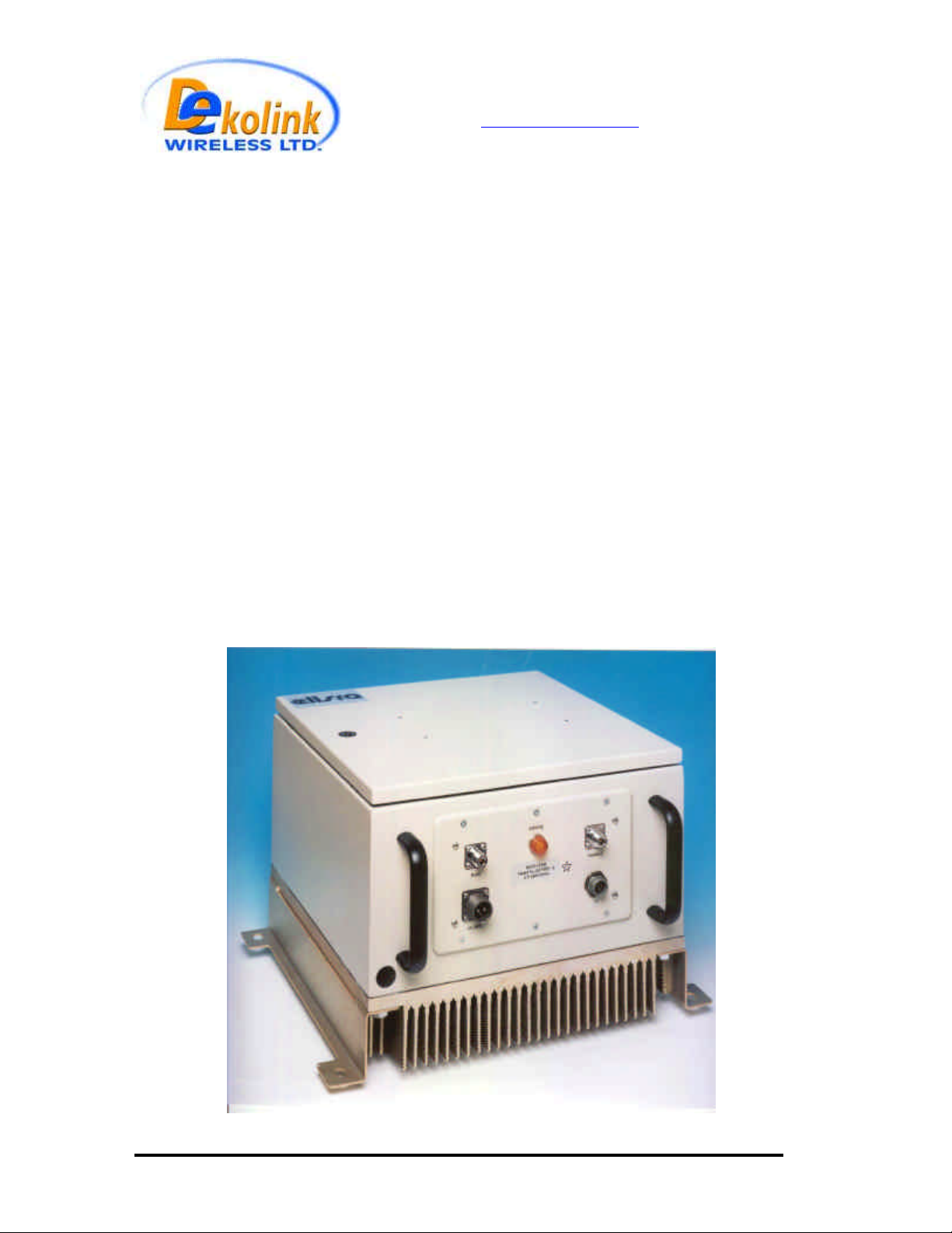
HIGH POWER REPEATER
MODEL: MW-BDA-ESMR-50W90
Page 1 of 14 50W rev 3 - 11/03
Page 2
Dekolink WIRELESS Ltd.
16 Bazel St. Qiryat-Arieh Petah-Tikva, Israel, 49510
Tel- 972-3-9180-180 Fax-972-3- -
e-mail: marketing@decolink.com web www.decolink.com
TABLE OF CONTENTS
PARAGRAPH PAGE No
REPEATER OVERVIEW 3
BLOCK DIAGRAM DESCRIPTION 3
REPEATER (BDA) CONNECTION 3
STEP ATTENUATOR & RF GAIN & SETTING 4
AGC FUNCTION 4
BDA MONITOR 5
BDA MONITOR FUNCTIONS 6
BDA INSTALLATION 8
BASE / DONOR ANTENNA INSTALLATION 8
REMOTE / MOBILE SERVICE ANTENNA INSTALLATION 8
ANTENNA ISOLATION 8
INSTALLATION STEPS 9
RF EXPOSURE WARNING 10
ELECTRICAL SPECIFICATIONS 11
MECHANICAL SPECIFICATIONS 11
ENVIRONMENTAL CONDITIONS 11
MECHANICAL LAYOUT 12
MECHANICAL OUTLINE 13
LIMITED WARRANTY 14
LIST OF DRAWINGS
DRAWING PAGE No
REPEATER(BDA) RF BLOCK DIAGRAM 4
BDA MONITOR 7
BDA MONITOR BLOCK DIAGRAM 7
MECHANICAL LAYOUT 13
MECHANICAL OUTLINE 13
Page 2 of 14 50W rev 3 - 11/03
Page 3

Dekolink WIRELESS Ltd.
16 Bazel St. Qiryat-Arieh Petah-Tikva, Israel, 49510
Tel- 972-3-9180-180 Fax-972-3- -
e-mail: marketing@decolink.com web www.decolink.com
REPEATER OVERVIEW:
The Bi-Directional Repeater assembly provides an exceptional repeater/booster
performance to extend the coverage area of radio communications in buildings
and RF shielded environments.
Features such as high linearity power amplifiers are contributing for the overall
improved system linearity performances. The unit is based on a duplexed path
configuration, having sharp out of band attenuation for improved isolation
between the receiving and transmitting paths.
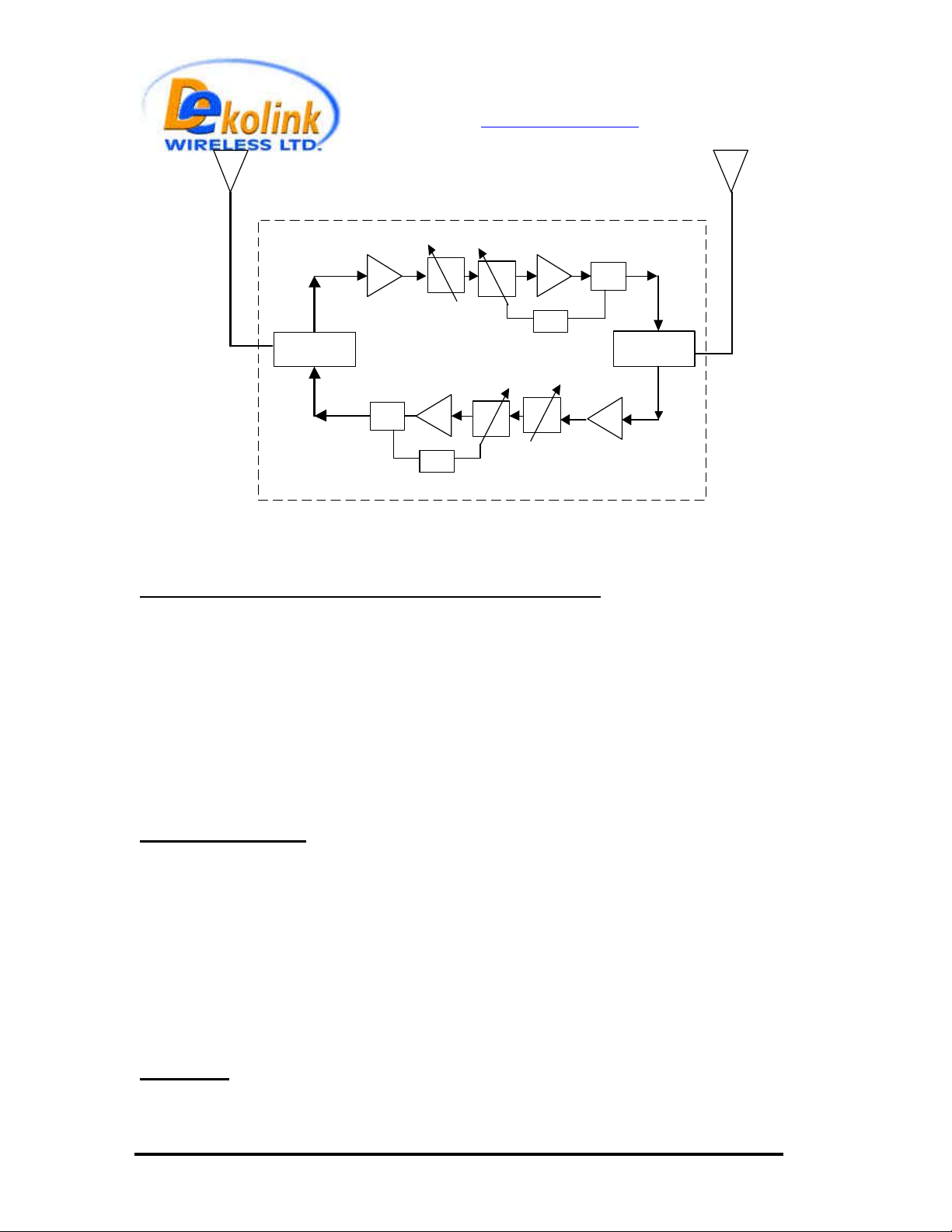
BLOCK DIAGRAM DESCRIPTION:
The Repeater Downlink path receives the RF signals from base station,
amplifies them and transmits them to the subscriber. The Repeater Uplink path
receives the RF signals from the subscriber, amplifies them and transmits them
to the base station. Two duplexers frequency separate the signals to the proper
amplifying path and isolate the two signals.
For each path two amplifiers do the path signal amplification; a low noise
amplifier (LNA) and a high power amplifier. The low noise amplifier has a 30 dB
step attenuator to set the gain of the specific path.
REPEATER (BDA) CONNECTION
The RF connection is made via two type “N” female connectors. The RF
connector labeled “Base” must be connected to the antenna pointing to the base
station; usually a rooftop antenna. The RF connection labeled “Mobile” must be
connected to the antenna pointing into the area to be covered by the Repeater
such as inside a building or outdoor shaded area.
Page 3 of 14 50W rev 3 - 11/03
Page 4
TO
BASE
Dekolink WIRELESS Ltd.
16 Bazel St. Qiryat-Arieh Petah-Tikva, Israel, 49510
Tel- 972-3-9180-180 Fax-972-3- -
e-mail: marketing@decolink.com web www.decolink.com
TO
MOBILE
PA
AGC
Power
Monitor
Duplexer
LNA
Duplexer
LNA
Power
Monitor
Attenuator
Downlink
PA
AGC
Attenuator
Uplink
BDA RF BLOCK DIAGRAM
STEP ATTENUATOR AND RF GAIN SETTING
For proper operation of the Repeater, the isolation between the base station antenna
and the mobile antenna should exceed the Repeater gain by at least 12 dB. If the
Repeater gain were higher than the isolation between the antennas, oscillation would
start and would saturate the amplifier. Isolation few dB higher than the Repeater gain
cannot start oscillations but would cause gain ripple in the band.
The step attenuator on the low noise amplifier reduces the Repeater gain. The Repeater
gain can be stepped down by the amount indicated on the step attenuator.
AGC FUNCTION
The Repeater has AGC function on both paths that serve to prevent the saturation of
the power amplifier. When a high signal is received the AGC circuit detects the
amplitude and sends a feedback signal to a variable attenuator, which attenuates the
signal level so that the output power of the amplifier does not exceed the preset limit.
The green LED on the BDA monitor (AGC Range) illuminates when the power output of
the amplifier is within the set limit. An On/Off switch on the connection box enables the
AGC function. If the AGC is disabled then the amplifier gives maximum gain.
WARNING: For proper operation the AGC switch must be ON to prevent
excessive spurious.
Page 4 of 14 50W rev 3 - 11/03
Page 5

Dekolink WIRELESS Ltd.
16 Bazel St. Qiryat-Arieh Petah-Tikva, Israel, 49510
Tel- 972-3-9180-180 Fax-972-3- -
e-mail: marketing@decolink.com web www.decolink.com
BDA MONITOR
The BDA monitor circuit monitors the following functions:
RF power transmitted by the power amplifiers.
For the downlink channel a red fault LED illuminates if the power is 10 dB below the
specified composite power. In normal use the downlink channel continuously transmits
RF signals and this LED should be on. When the donor reception from the base is bad
this LED turns on to warn that the repeater is not being used efficiently. Another green
LED illuminates when the power reaches or exceeds this power (10W). This is used to
set the repeater gain. This limit is the same as the AGC limit and is factory preset.
For the uplink channel a green indicator LED illuminates when the power reaches or
exceeds its composite power (1W). When the isolation between the antennas is bad this
LED lits permanently. This LED should turns on only when a near by cellular is used.
This limit is the same as the AGC limit and is factory preset.
DC voltage of the channels. The fault LED illuminates when the voltage is below or
above the specified limits.
DC current to each of the two LNAs and the uplink power amplifier. If the current is
below or above the specified limits then a LED illuminates.
Page 5 of 14 50W rev 3 - 11/03
Page 6

Dekolink WIRELESS Ltd.
16 Bazel St. Qiryat-Arieh Petah-Tikva, Israel, 49510
Tel- 972-3-9180-180 Fax-972-3- -
e-mail: marketing@decolink.com web www.decolink.com
BDA MONITOR FUNCTIONS
P.S. (Uplink & down link) Illuminates when the Power Supply voltage is below or above
its limits.
P.AMP. (Uplink) Illuminates when the uplink Power Amplifier current is above or below
its specified limits
P.AMP. (Downlink) Illuminates when the uplink RF Power is 10 dB below the specified
composite power.
L.N.A. (Uplink & Downlink) Illuminates when the Low Noise Amplifier current is above
or below its specified limits.
AGC Range. (Downlink) This green LED on the downlink path illuminates when the
transmitted power reaches or exceeds the AGC set power, which is the maximum
specified composite power. For best efficient use of repeater RF power this LED should
be on.
AGC Range. (Uplink) This green LED on the downlink path illuminates when the
transmitted power reaches or exceeds the AGC set power, which is the maximum
specified composite power. This LED should not lit permanently. It lights only when a
nearby mobile is transmitting.
The Pushbutton Switch on the BDA monitor turns on all the alarms. This is used to
test the alarm functions of the BDA.
REMOTE ALARM The BDA monitor has a dry contact relay arms output. These
contacts are short circuit at no fault and open circuit at any fault or at power loss. This
function can be used to operate a modem for remote alarm warning. The relay contacts
are connected to pins A and C (small pins) on the alarm connector at the front panel.
Page 6 of 14 50W rev 3 - 11/03
Page 7

Dekolink WIRELESS Ltd.
16 Bazel St. Qiryat-Arieh Petah-Tikva, Israel, 49510
Tel- 972-3-9180-180 Fax-972-3- -
e-mail: marketing@decolink.com web www.decolink.com
BDA
MONITOR
BLOCK
DIGRAM
DOWNLINK
P.AMP.
L.N.A.
INPUT
SUPPLY
DOWNLINK
CHANNEL
RF POWER
DETECTION
UPLINK
CHANNEL
INPUT
SUPPLY
RF POWER
DETECTION
P.S.
AGC
Range
P.AMP.
L.N.A.
Range
VOLTAGE
SENSOR
CURRENT
SENSOR
POWER
SENSOR
POWER
SENSOR
RELAY
VOLTAGE
SENSOR
CURRENT
SENSOR
SENSOR
POWER
SENSOR
UPLINK
P.S.
AGC
P.AMP ALARM
P.AMP ALARM
LNA ALARM
AGC RANGE
INDICATOR
PS ALARM
LNA ALARM
AGC RANGE
INDICATOR
RELAY ALARM
PS ALARM
ALARM TEST
PUSHBUTTON
LNA D.L/
SUPPLY
LOW POWER ALARM
(P.AMP)
HIGH POWER DETECTION
(AGC Range)
U.L. PA SUPPLY
(P.AMP)
LNA U.L.
SUPPLYCURRENT
HIGH POWER DETECTION
(AGC Range)
Page 7 of 14 50W rev 3 - 11/03
Page 8

Dekolink WIRELESS Ltd.
16 Bazel St. Qiryat-Arieh Petah-Tikva, Israel, 49510
Tel- 972-3-9180-180 Fax-972-3- -
e-mail: marketing@decolink.com web www.decolink.com
BDA INSTALLTION
Install the BDA Repeater in a shielded, ventilated and easy to reach area. Use low loss
cables to connect antennas to the BDA. Install the BDA close to the service area to
improve output power and noise figure.
The BDA Base/Donor connector port is connected to donor antenna, usually a Yagi
antenna, while the BDA Mobile/Remote connector port is connected to a mobile
antenna; outdoor indoor.
BASE / DONOR ANTENNA INSTALLTION
Typically this is a directional antenna such as Yagi or Dish antenna of 10 to 15 dB gain.
This antenna is pointed to the base station to get maximum input power. This antenna
should be in line of sight with the base site. Raise this antenna higher if no line of site is
achieved. The required Base signals should be the dominant signals; at least 6 dB
higher power than other signals.
Choose the antenna site to get the maximum isolation from the remote (mobile serving)
antenna.
REMOTE / MOBILE ANTENNA INSTALLTION
The remote antenna is an Omni antenna or a directional antenna according to the
coverage requirements.
For indoor applications covering a large building, the RF signals are split using power
dividers and distributed to many antennas each covering a floor or a small area.
ANTENNA ISOLATION
For proper operation the isolation between these two antennas must be at least 12 dB
higher than the BDA gain. Lower isolation would lead to high in-band ripple. Oscillations
will build up when the isolation is lower than BDA gain.
The isolation between the antennas is critical for high gain outdoor repeaters.
To measure the isolation; inject a known signal into one antenna and measure the
power at the other antenna. This should be done across the frequency range of both
uplink and downlink bands.
Page 8 of 14 50W rev 3 - 11/03
Page 9

Dekolink WIRELESS Ltd.
16 Bazel St. Qiryat-Arieh Petah-Tikva, Israel, 49510
Tel- 972-3-9180-180 Fax-972-3- -
e-mail: marketing@decolink.com web www.decolink.com
INSTALLATION STEPS
1. Install all antennas and connect them to the BDA inputs.
2. Turn the AGC On for both Uplink and Downlink power amplifiers. This AGC limits
the output power of the BDA to the desired level.
WARNING: For proper operation the AGC switch must be ON to prevent
excessive spurious beyond FCC limitation.
The AGC on the Downlink path guarantees constant downlink power when and if
the Donor power changes.
3. Set downlink gain to minimum; uplink gain to minimum.
4. Increase the downlink channel gain till the green LED turns from off to on. This is
the best gain setting giving highest usable power.
5. The green LED on the downlink power amplifier will illuminate if adequate donor
power has reached the BDA. If the donor power is low the LED will not lit and the
BDA usable power is not used efficiently. The red LED will illuminate if the donor
power is 10 dB or more below the maximum usable power indicating a fault.
6. Set the uplink gain to the same as the downlink gain.
7. Check that the uplink green LED on the BDA monitor does not lit permanently. This
LED would lit permanently If the isolation between antennas is low (BDA
oscillations) or the BDA is faulty. In such a case:
• Disconnect one of the cables from the BDA connectors and connect a load
at the connectors.
• If the LED on this amplifier illuminates permanently then the BDA is faulty
(oscillating) and needs replacing.
• If the LEDs stops illuminating then the isolation between the donor and
remote antennas is low. Either improve the isolation (e.g. increase
separation) or reduce BDA gain.
• To reduce gain, reconnect the antenna cables. Reduce the gain at both
uplink and downlink path until this LED stops illuminating. Reduce the gain
further by 10 dB. This is the maximum usable gain.
Page 9 of 14 50W rev 3 - 11/03
Page 10

Dekolink WIRELESS Ltd.
16 Bazel St. Qiryat-Arieh Petah-Tikva, Israel, 49510
Tel- 972-3-9180-180 Fax-972-3- -
e-mail: marketing@decolink.com web www.decolink.com
RF EXPOSURE WARNING
In order to satisfy the FCC RF exposure requirements, you must ensure that the
installation complies with the following:
One antenna is connected via cable that has typical 1~10 dB attenuation
(depends on the length of the cable) to the BDA base port. This antenna is
installed outdoor and has very sharp beam (Yagi type or similar) pointed to the
donor (BTS). This type of antenna has about 10 dBi gain. Typical specifications:
gain: 8 dBd (=10.1 dBi), VSWR: better than 1.5:1 , Impedance: 50 ohm. The
outdoor antenna must be installed to provide a minimum separation distance of
1 m (100 cm) from persons within the area.
The second antenna is connected via cable that has typical 1~10 dB attenuation
(depends on the length of the cable) to the BDA MOBILE port. This type of
antenna is omnidirecttional (isotropic), or wide beam, with 0 to 2 dBi typical gain
and is installed and distributes indoor (in buildings, tunnels, basements, park
lots, shopping centers etc.). Typical specifications: gain: 2 dBi, VSWR: better
than 2:1 , Impedance: 50 ohm. For direct connection to the BDA this antenna
must be installed to provide a minimum separation distance of 2 m (200 cm)
from persons within the area.
Less separation is needed if the power from this power is divided into many
antennas covering many floors or areas.
Page 10 of 14 50W rev 3 - 11/03
Page 11

Dekolink WIRELESS Ltd.
16 Bazel St. Qiryat-Arieh Petah-Tikva, Israel, 49510
Tel- 972-3-9180-180 Fax-972-3- -
e-mail: marketing@decolink.com web www.decolink.com
ELECTRICAL SPECIFICATIONS:
SPECIFICATIONS PARAMETER
Down Link Up Link
Frequency Range 851-866 MHz 806-821MHz
Gain 90±4 dB
Pass Band ripple <3 dB p-p
Manual Attenuation Range 0 to 30dB in 2dB Step
Noise Figure 5dB
Output Power @ 1 dB compression 50W 16W
3rd order intercept point 62 dBm typ. 50 dBm typ.
Composite Power Output, max +40dBm +31dBm
Down Link IMD @ two tone 37dBm each 50 dBc --------------------
Up Link IMD @ two tone
27dBm each
AGC Factory set level (nom.) 40 dBm 31 dBm
AGC range 15 dB 20 dB
Impedance 50 Ohms
VSWR <1.5:1
Rx/Tx Isolation > 100 dB
Fault Monitoring LED indication for each fault
Remote Alarm Summarized alarm by dry contact
Power Supply AC 110/220V/50Hz Range: 176~264V, 45~65Hz
Mechanical Specifications:
Size 400X400X300 mm approx.
RF Connectors N-type Female
Weight 30 kg. Approx.
Enclosure Type Weatherproof Enclosure for Wall Mounted
Environmental Conditions:
Operating temperature
Humidity 95%
Weatherproof conditions Protected to IP65
------------------- 44 dBc
Option +28 VDC
Installation
-30°C to +50°C
Page 11 of 14 50W rev 3 - 11/03
Page 12

Dekolink WIRELESS Ltd.
16 Bazel St. Qiryat-Arieh Petah-Tikva, Israel, 49510
Tel- 972-3-9180-180 Fax-972-3- -
e-mail: marketing@decolink.com web www.decolink.com
Uplink
Amplifier
Downlink Uplink FUSE Power
AGC AGC 10A ON/OFF
ON/OFF ON/OFF
MECHANICAL LAYOUT
Uplink
Preamplier
BDA
MONITOR
Page 12 of 14 50W rev 3 - 11/03
Downlink
Preamplier
Downlink
Ampifier
Page 13

Dekolink WIRELESS Ltd.
16 Bazel St. Qiryat-Arieh Petah-Tikva, Israel, 49510
Tel- 972-3-9180-180 Fax-972-3- -
e-mail: marketing@decolink.com web www.decolink.com
MECHANICAL OUTLINE
Page 13 of 14 50W rev 3 - 11/03
Page 14

Dekolink WIRELESS Ltd.
16 Bazel St. Qiryat-Arieh Petah-Tikva, Israel, 49510
Tel- 972-3-9180-180 Fax-972-3- -
e-mail: marketing@decolink.com web www.decolink.com
DEKOLINK WIRELESS
LIMITED WARRANTY
Dekolink Wireless [Ltd.] (“Dekolink”), manufacturer of this product (the “Product”)
warrants to the original purchaser (“Purchaser”) that the Product is free from defects in
materials and workmanship for a term that ends on the earlier of twelve (12) months from
the date of activation of the Product or fifteen (15) months from the date of shipment of
the Product by Dekolink. The obligations of Dekolink under this warranty shall be limited
solely to the repair or exchange or giving credit for, at the option of Dekolink, any Product
that may prove defective in accordance with evidence satisfactory to Dekolink. Any repair
or replacement of the Product by Dekolink shall not extend the original warranty period.
This warranty is exclusive to the original Purchaser and is not assignable.
This warranty applies only upon the condition that the Product has been installed,
maintained and operated under conditions of normal use. The provisions of this warranty
shall not apply if, in Dekolink’s judgment, the Product has been subject to misuse or
neglect, damaged in an accident or by act of vandalism, or repaired or altered in any way
that adversely affects its performance or reliability.
To obtain warranty service, Purchaser may, upon the prior written authorization of
Dekolink or its authorizerd service representative, return the defective Product to
Dekolink’s authorized service center. All shipping and insurance charges are the sole
responsibility of Purchaser and are not included in this warranty.
Dekolink expressly excludes and disclaims all other warranties, including but not limited to
any warranties of merchantability or fitness for a particular purpose.
Dekolink shall in no event be liable for any special, indirect, incidental, consequential or
punitive damages or for loss, damage, or expense, including loss of use, profits, revenue, or
goodwill, directly or indirectly arising from purchaser’s use or inability to use the
merchandise, or for loss or destruction of other property or from any other cause, even if
Dekolink. has been advised of the possibility of such damage. some states do not allow the
exclusion or limitation of incidental or consequential damages so these limitations may not
apply under certain circumstances.
The liability of Dekolink shall in no event exceed an amount equivalent to the purchase price
paid by the purchaser for the defective product.
This warranty shall not be extended, altered or varied except by a written instrument duly
signed by Dekolink.
Page 14 of 14 50W rev 3 - 11/03
 Loading...