

Deka G45, G75, G105 Service Manual


Table of Contents
age
P
INTRODUCTION ………………………………………………… 2
SECTION I - THEORY OF
OPERATION/BATTERY CONSTRUCTION …………………… 4
Discharging/Recharging Characteristics…………………… 4
Battery Ratings ……………………………………………… 4
Battery Voltage ……………………………………………… 4
Ampere Hour (AH) …………………………………………… 5
Kilowatt Hours (KWH) ……………………………………… 5
Positive Plate Capacity ……………………………………… 5
Specific Gravity ……………………………………………… 5
Specific Gravity During Recharge ………………………… 5
rid Casting ………………………………………………… 6
G
Apply Active Material………………………………………… 6
Curing and Drying …………………………………………… 6
Plate Formation ……………………………………………… 6
Wrapping Positive Plates …………………………………… 6
Assembling An Element …………………………………… 7
Finishing the Cell Assembly ………………………………… 7
Assembling into Trays ……………………………………… 8
Battery Finishing and Shipping……………………………… 8
SECTION II - BATTERY SAFETY ……………………………… 9
Hazardous Elements ………………………………………… 9
Wearing Protective Clothing………………………………… 9
Lifting Batteries ……………………………………………… 9
Using the Battery as a Counterbalance …………………… 9
CHARGING BATTERIES
Charging Areas — Proper Equipment …………………… 10
Charging Areas — Proper Ventilation …………………… 10
Connecting/Disconnecting Charger ……………………… 10
Sparks/Open Flames ……………………………………… 10
age
P
SECTION III - INSTALLATION AND USE (Cont.)
Operation of the Battery …………………………………… 13
Specific Gravity and On-Charge
Cell Voltage Temperature Correction……………………… 13
BATTERY CHARGING ………………………………………… 13
Basic Charging Facts ……………………………………… 13
Specific Gravity Temperature Correction ………………… 14
Charging Methods…………………………………………… 14
The Charging Process ……………………………………… 14
Improper Charging ………………………………………… 16
Charging Safety……………………………………………… 16
SECTION IV - BATTERY MAINTENANCE
AND TROUBLE SHOOTING …………………………………… 16
Reading Hydrometers and Thermometers ……………… 17
Using a Voltmeter …………………………………………… 17
Battery Inspection …………………………………………… 17
Adding Water/Adjust Electrolyte Levels…………………… 18
Battery Cleaning Wash Unit ……………………………… 18
Performing a Test Discharge ……………………………… 19
Correcting a Sulfated Battery ……………………………… 19
Procedure for Adjusting the
Specific Gravity of the Electrolyte of a Battery …………… 20
Storage Battery Troubleshooting Chart …………………… 21
Basic Rules for Battery Care and Maintenance ………… 23
SECTION V - VALVE REGULATED
LEAD-ACID BATTERIES ……………………………………… 24
Operation of a Gel Cell……………………………………… 24
Charging a Gel Cell ………………………………………… 24
Operating Instructions ……………………………………… 25
Maintenance Instructions…………………………………… 26
HANDLING ACID
Pouring Acid ………………………………………………… 10
Mixing Electrolyte …………………………………………… 10
First Aid for Acid Splash …………………………………… 10
Eye Wash and Emergency Shower Facilities …………… 11
Neutralizing Acid and Electrolyte ………………………… 11
Repairing Batteries ………………………………………… 12
SECTION III - INSTALLATION AND USE …………………… 12
Receiving a Battery ………………………………………… 12
Temporary Storage ………………………………………… 12
Placing a Wet Charged Battery in Service ……………… 12
Placing a Dry Charged Battery in Service ………………… 13
Cycling Characteristics……………………………………… 13
INTRODUCTION
Storage batteries do not store electrical energy, but convert electrical energy into chemical energy which is slowly accumulated as the
charge progresses. A battery in use is said to be on discharge.
During discharge, the chemical energy stored in the battery is converted into usable electrical energy.
A lead-acid motive power battery supplies direct current (DC)
power to electric lift trucks, tractors and pallet trucks. This type of
battery consists of a metal tray containing cells, connected in series.
These batteries come in a wide variety of shapes, sizes, voltages
and ampere-hour capacities.
Each cell in a motive power battery contains positive and negative
plates. All of the positive plates are joined in parallel to the positive
post and strap, to form a positive group. The negative plates also are
joined in parallel to the negative post and strap to form a negative
group. These groups are separated and insulated from one another
and they are immersed in a solution of sulfuric acid and water, called
electrolyte. These groups of plates, separators, posts and straps are
called an element and it is contained in an acid-proof plastic jar.
SECTION VI - BATTERY REPAIR
Repair or Replace …………………………………………… 27
Gas Purging ………………………………………………… 27
Removing Connectors ……………………………………… 27
Removing a Cell …………………………………………… 27
Removing an Element ……………………………………… 28
Reassembling the Battery ………………………………… 29
Using Sealing Compound ………………………………… 30
Attaching Intercell Connectors …………………………… 30
Replacing Acid and Charging ……………………………… 30
SECTION VII - SAFETY DATA SHEETS ………………… 31-48
GLOSSARY OF BATTERY TERMINOLOGY …………… 49-53
The cutaway illustration (Fig. A-1) shows the construction of an
East Penn battery cell. Each positive plate consists of a lead-alloy
grid structure which is filled with a paste of active material, made
from lead oxide. The active material is forced into the positive grid
structure during manufacturing and is held firmly to the grid by a system of vertical and horizontal glass fiber mats, which reinforce and
insulate the positive plate. A retainer and bottom shield encase each
positive plate and mat assembly to help prevent short circuits.
The negative plate also consists of a lead alloy grid structure that
is filled with active material. But because negative plates undergo
much less active material shedding, no reinforcing glass fiber mats
are needed. Separators provide insulation between the positive and
negative plates. The positive and negative plates are connected to
their respective posts by positive and negative straps.
A more detailed description of battery construction appears in
Section I.
2

Manufactured using the world’s most modern computer integrated manufacturing techniques…
COVER
Heat sealed with lead insert
bushing prevents leakage and
voltage-to-ground.
O-RING SEAL
Accomodates positive plate growth
without cover distortion and leakage.
POST
Special alloy for increased
strength and conductivity.
POST PLATE STRAP
Extra heavy to ensure a permanent
connection between posts and plates.
POSITIVE GRID
A non-porous lead alloy casting
designed for maximum current
carrying capacity, capable of many
years of dependable service.
Lead alloy is manufactured on-site
and undergoes rigid testing before,
during and after casting.
ACTIVE MATERIAL
Manufactured on-site to exacting
specifications and uniformly applied
under rigid laboratory control to
ensure maximum efficiency
throughout long battery life.
JAR
Molded of high impact-resistant
material to remain leak-free under
the roughest conditions.
BRIDGE
Provides firm element support
and ample sediment space.
BOTTOM SHIELD
Provides extra protection on bottom
of positive plate to prevent shorting
between plate and sediment.
STEEL TRAY
Heavy gauge with acid-resistant
protective coating. Steel covers
furnished as required.
VENT CAP
Quarter-turn bayonet style
simplifies watering and
inspection.
SEPARATOR GUARD
White color increases
visibility for fast electrolyte
check. Solid insulating guard
extends beneath the straps to
prevent shorting between the
plates and straps.
NEGATIVE PLATE
Engineered to complement
positive plate performance.
VERTICAL MAT
Laminated construction comprised of uniformly spaced,
fine glass tape that imbeds
into the active material.
Also features an inter-woven
glass fiber mat wrapped
vertically around the positive
plate ensuring optimum active
material retention.
HORIZONTAL MAT
Made of glass fibers with an
insoluble binder. Breaks up
gas bubbles and increases
positive plate insulation and
performance.
RETAINER
A high porosity perforated
envelope that encases positive
plates and glass mats to
prevent shorts and ensure
maximum performance and life.
SEPARATOR
Impervious to heat, acid and
corrosion, deep channeled,
microporous separators provide
insulation between positive and
negative plates while allowing
the free flow of electrolyte
throughout the cell.
ELECTROLYTE
In ample volume to ensure
top performance at all rates
of discharge.
Fig. A-1
3

SECTION I - THEORY OF OPERATION/BATTERY CONSTRUCTION OF LEAD ACID STORAGE BATTERIES
Theory of Operation
Discharging/Recharging
Characteristics
In a fully charged condition the active material in the positive
plate is lead peroxide (PbO
ative plates is sponge lead (Pb). The electrolyte has maximum
sulfuric acid content and its temperature corrected specific
gravity ranges should comply with the manufacturer’s recomme n ded fu l l char ge spe cifi c grav ity spe cifi cati ons
(See Table 1-1 ). (See Table 3-1 - shown on page 14 - Specific
ravity Temperature Corrections).
G
) and the active material in the neg-
2
Battery Type Range @ 77°F/25°C
Recommended Specific Gravity
Standard “D” Series 1.280 - 1.295
Maintenance Saver “M” Series 1.245 - 1-255
Max Powr “P” Series 1.320 - 1.330
Diesel Starting “DL/DLU” Series 1.245 - 1.255
Hydra Saver “H” Series 1.295 - 1.305
Table 1-1
When fully charged, each cell has a voltage of approximately
two (2) volts on open circuit. However, a cell may have a voltage from 2.12 to 2 .70 vo lts wh ile be ing ch arged. A cell
develops a voltage potential when two dissimilar metals are
immersed in a suitable electrolyte. The two metals used in leadacid cells are lead peroxide (PbO
the electrolyte is dilute sulfuric acid (H
of dissimilar metals and electrolyte results in a voltage potential
) and sponge lead (Pb), and
2
). This combination
2SO4
of nominally two (2) volts per cell and their potential ability to
deliver this voltage under varying load and for varying periods
of time.
When a battery is discharged, the internal components of each
cell undergo chemical changes (Figure I-1). During the discharge cycle, the composition of the positive plates changes
from lead peroxide (PbO
ative plates from sponge lead (Pb) to lead sulfate (PbSO
sulfate on both the positive and negative plates comes from the
) to lead sulfate (PbSO4) and the neg-
2
) The
4
sulfuric acid in the electrolyte solution combining chemically
with the active material of the plates. This chemical reaction
reduces the sulfuric acid content in the electrolyte. The specific
gravity of the electrolyte is reduced and approaches that of
water (1.100). Cell voltage decreases during the discharge
because the two (2) dissimilar metals (PbO
becoming more similar (PbSO
).
4
) and (Pb) are
2
Fig. I-1
Battery Ratings
During charging, the discharging reaction is reversed and the
chemical energy is restored. The lead sulfate on the positive
plates converts back to lead peroxide (PbO
fate on the negative plates converts back to sponge lead (Pb).
The released sulfate returns to the electrolyte solution, increasing the sulfuric acid content, which in turn increases the specific
gravity. When these electrochemical reactions are complete,
the cell is again fully charged.
During charging, hydrogen gas is formed on the negative plates
and oxygen is formed on the positive plates. This explosive gas
mixture is vented from the battery through the vent/filler caps.
THE WARNINGS (SHOWN ON PAGE 5) APPLY TO ALL
CELLS OR BATTERIES.
) and the lead sul-
2
A single lead-acid cell does not have sufficient power to handle
most requirements. However connecting a number of cells
together in series results in a battery capable of supplying higher power demands.
Battery Voltage
The number of cells is determined by the required nominal
operating voltage of the equipment. Since each cell has a nominal voltage of two (2) volts, a 36 volt industrial truck will require
an 18-cell battery (18 cells x 2 volts/cell = 36 volts).
4

SECTION I - THEORY OF OPERATION/BATTERY CONSTRUCTION OF LEAD ACID STORAGE BATTERIES (cont.)
M
anufactured by:
East Penn Manufacturing Co.
102 Deka Road,
Lyon Station, PA 19536
610-682-6361 USA
PROPOSITION 65 WARNING: Battery posts, terminals and related
a
ccessories contain lead and lead compounds, chemicals known
t
o the State of California to cause cancer and reproductive harm.
B
atteries also contain other chemicals known to the State of
California to cause cancer. WASH HANDS AFTER HANDLING.
W
ARNING: Risk of fire, explosion or burns. Do not disassemble
o
r incinerate. Not recommended for inverted use. Follow product
charging instructions. High Voltage: Risk of shock. Do not touch
uninsulated terminals or connectors.
K
eep Vent Caps Tightly in Place
Harmful if swallowed, inhaled, or in contact with skin.
A
cid causes severe skin burns and eye damage.
M
ay damage fertility or the unborn child if ingested
o
r inhaled.
M
ay cause harm to breast-fed children.
May cause cancer if ingested or inhaled.
C
auses skin irritation, serious eye damage.
Contact with internal components may cause
i
rritation or severe burns.
Causes damage to central nervous system, blood
and kidneys through prolonged or repeated
exposure if ingested or inhaled.
Irritating to eyes, respiratory system, and skin.
May form explosive air/gas mixture during charging.
Extremely flammable gas (hydrogen).
Explosive, fire, blast or projection hazard.
Obtain special instructions before use.
Do not handle until all safety precautions have
b
een read and understood.
Wash thoroughly after handling.
Do not eat drink or smoke when using this product.
Avoid contact during pregnancy/while nursing.
Wear protective gloves/protective clothing, eye
protection/face protection.
Use only outdoors or in a well-ventilated area.
Avoid contact with internal acid.
Do not breathe dust/fume/gas/mist/vapors/spray.
K
eep away from heat/sparks/open flames/hot
surfaces. No smoking.
I
F SWALLOWED OR CONSUMED: rinse mouth.
Do NOT induce vomiting. Call a poison center/
d
octor if you feel unwell.
IF ON CLOTHING OR SKIN (or hair): Remove/Take
o
ff immediately all contaminated clothing and wash
it before reuse. Rinse skin with water/shower.
I
F INHALED: Remove person to fresh air and keep
comfortable for breathing. Immediately call a
POISON CENTER or doctor/physician.
IF IN EYES: Rinse cautiously with water for several
minutes. Remove contact lenses, if present and
easy to do. Continue rinsing.
If exposed/concerned, or if you feel unwell seek
medical attention/advice.
Store locked up, in a well-ventilated area, in
accordance with local and national regulation.
Dispose of contents/container in accordance
with local and national regulation.
Keep out of reach of children.
Lead Acid
Battery
Electrolyte
(Sulfuric Acid)
DANGER
Contains: Lead, Sulfuric Acid (Electrolyte), Lead Compounds.
Danger
See P.23 for full warranty information.
HYDROGEN GAS FROM THE BATTERY OR CELL CAN
EXPLODE. DO NOT SMOKE, USE AN OPEN FLAME, OR
CREATE AN ARC OR SPARKS IN THE VICINITY OF INDIVIDUAL CELLS OR BATTERIES. VENTILATE WELL WHEN
IN AN ENCLOSED SPACE AND WHEN CHARGING.
THIS BATTERY OR INDIVIDUAL CELL CONTAINS SULFURIC ACID WHICH CAUSES SEVERE BURNS. DO NOT GET
IN EYES, ON SKIN OR ON CLOTHING. IN CASE OF CONTA C T, FL USH IMMED IATE LY W ITH CLEAN WATE R.
OBTAIN MEDICAL ATTENTION IF EYES ARE AFFECTED.
PERSONAL SAFETY EQUIPMENT IS RECOMMENDED
WHEN WORKING WITH BATTERIES AND SHOULD BE
USED IN ACCORDANCE WITH LOCAL REQUIREMENTS;
SA F ETY GLA SSES , G O GGL E S O R A FA C E S HIEL D.
RUBBER OR PLASTIC GLOVES AND A RUBBER OR PLASTIC APRON ARE ITEMS OFTEN USED IN THIS TYPE OF
WORK. EQUIPMENT WHICH WILL PROTECT THE EYES
FROM ACID SPLASHES IS THE MOST IMPORTANT SINCE
THE EYES CAN BE SERIOUSLY AFFECTED IN A VERY
SHORT TIME.
Ampere Hour (AH)
The elect rical c apabilit y of a stora ge ba ttery i s usually
expressed in ampere-hours. The ampere-hour capacity is the
number of ampere-hours which can be delivered under specified conditions of temperature, rate of discharge, and final
voltage. Basically, ampere-hours are determined by multiplying
the number of amperes which the battery will deliver by the
number of hours during which the current is flowing. Example:
100 amperes x 6 hours to 1.70 volts per cell = 600 amperehours (six hour rate). The size and number of plates which
make up the element then determine total cell or battery capacity. Due to the va riety of job require ments bat teries ar e
produced with many different sizes of cells.
Kilowatt Hours (KWH)
Battery capacity is also expressed in kilowatt-hours (KWH),
which is the product of ampere x time x average volts per cell
during discharge. Example: 100 amps x 6 hours x 1.930 average volts per cell = 1,158 watt hours ÷ 1000 = 1.158 KWH. For
an 18-cell battery, the capacity would be 1.158 x 18 = 20.84
KWH. Increasing or decreasing the size of the cells or the number of cells in the battery can vary the kilowatt-hour rating.
Positive Plate Capacity
Positive plate capacity is the ampere delivery for a fixed period
of time (usually six hours) for a particular size positive plate. A
Deka D100 type positive plate has the capability of delivering
16.66 amperes for six hours or 100 ampere hours (16.66 x 6 =
100 AH) to a final voltage of 1.70. Increasing or decreasing the
number of positive plates in the cell can vary this ampere-hour
rating or capacity. In the previous examples, the battery is an
8-cell, D100-13 plate unit. To determine the number of positive
1
plates in each cell, subtract one from the total number of plates
in the cell and divide by two. Example: 13 – 1 = 12 ÷ 2 = 6 positive plates per cell; 6 positive plates x 100 ampere-hours each =
600 AH. The use of a different type of positive plate, such as a
D75 or D125, will respectively decrease or increase the
ampere-hour capacity. The above ratings are based on an electrolyte temperature of 77°F/25°C with a full charge specific
gravity at battery nameplate rating.
Specific Gravity
The term specific gravity describes the ratio of the density of
electrolyte to the density of water. Electrolyte weighing 1.2
times as much as the same volume of water has a specific
gravity of 1.200. The full charge specific gravity of a cell is a
matter of design and depends on several factors. The specific
gravity must be high enough to contain the amount of sulfuric
acid necessary to meet the chemical needs of a cell. If the sulfuric acid content is too high, damage may result to the cell.
Since the acid content of the electrolyte decreases linearly as
the cell is discharged, the decrease in specific gravity is directly
proportionate to the amount of ampere-hours removed (refer to
Table 3-2, page 15).
The specific gravity at any point in the discharge indicates the
depth of discharge and can be translated into ampere-hours
removed. A cell having a full charge specific gravity of 1.290
and a final specific gravity of 1.140 will have a specific gravity
drop of 150 points. Example: Assume the specific gravity is
1.190 at the end of the discharge. That is 100 points specific
gravity below the full charge gravity; therefore, = 67% dis-
100
150
charged of rated capacity. Allow at least one
hour after end of discharge for the electrolyte to diffuse and give
a true reading corrected to 77°F/25°C.
The linear relation of specific gravity to state of discharge can
be used in tests to determine power consumption or capacity
required. Tests of this kind can be made to demonstrate that a
lift truck may require a larger capacity battery to do the job, and
can lead to the solution of a problem.
Specific Gravity During Recharge
The rise in specific gravity during recharge is not uniform or proportional to the amount charge returned in ampere-hours.
During the early part of the charge, there is no gassing action to
mix the electrolyte with the heavier acid being released from the
plates. The heavier sulfuric acid will lay on the bottom. A
hydrometer reading which draws electrolyte from the top of the
cell does not indicate the true specific gravity or actual state of
charge. During the gassing portion of the charge, the sulfuric
acid mixes, and the specific gravity rises rapidly to full charge
value.
5

SECTION I - THEORY OF OPERATION/BATTERY CONSTRUCTION OF LEAD ACID STORAGE BATTERIES (cont.)
Battery Construction
Grid Casting Positive and Negative Grids
A plate consists of a cast lead-alloy grid structure into which
lead oxide pastes are applied. Since lead by itself would be too
soft and flexible to make a grid, a certain amount of antimony is
added to the grid to prevent it from sagging or warping. The
grids are then cast by pouring the molten alloy into grid molds.
Negative
Grid
Positive
Grid
Fig. I-2
Due to the increased amount of chemical activity that takes place
on the positive grids during charging and discharging, positive
grids are more heavily constructed than negative grids (Fig. I-2).
Apply Active Material
After the gri ds have been cast , the lead oxid e pastes are
applied. The lead oxide applied to the negative grid contains an
expander to produce sponge lead. The positive plate contains a
putty-like mixture of lead, lead oxide, lead sulfate and water.
Because proper pasting is critical to battery performance, East
Penn uses highly sophisticated, computer-controlled pasting
machines to consistently apply paste to exact thicknesses and
weight.
Fig. I-3
and life. The formed plates become darker and are individually
inspected (Fig. I-4 and Fig. I-5) to be sure that each one is perfect. This is important because many other companies form
their plates in the battery, or in groups of cells, resulting in temperature variation between plates, and they can’t individually
inspect each one.
Fig. I-4
Curing and Drying
After the plates are pasted, they must be cured and dried in a
rigidly controlled environment. This securely binds the active
material to the grid and produces a smooth, uniform plate. The
active material, now highly porous, allows the electrolyte to
penetrate freely so it can produce maximum conductivity
between the paste and the grid for high cell efficiency. Because
the curing and drying process is so important to cell efficiency
and battery life, East Penn has invested in humidity and temperature-controlled curing ovens (Fig. I-3), which produce the
highest quality plates in the industry.
Plate Formation
The cured plates must now undergo a formation charge, which
transforms the previously inert material on the positive plates
into lead peroxide and the material on the negative plates into
sponge lead. The plates are lowered into a forming tank filled
with dilute sulfuric acid, then temporarily connected to a lead
bar, and given a computer-controlled forming charge. Individual
plate formation allows the entire row of plates to be formed at
uniform temperatures, which will enhance battery performance
Fig. I-5
Wrapping Positive Plates
The active material of positive plates (lead peroxide) is subject to
shedding as a cell goes through its normal discharge/recharge
cycle. The small particles that are shed settle to the bottom of
the cell. To keep the active material firmly on the positive plates,
6

SECTION I - THEORY OF OPERATION/BATTERY CONSTRUCTION OF LEAD ACID STORAGE BATTERIES (cont.)
plate, to the desired cell size. Both outside plates are negative,
therefore the number of plates per cell is always an odd number, with each cell having one more negative then positive
plate.
The separators used to insulate the positive plate from the negative plate are grooved on one side and flat on the other (Fig.
I-7). The grooved side faces the positive plate. The flat side
faces the negative plate because the sponge lead of the negative plate would expand if it faced into the grooved side. In
some cases, positive plates can be inserted into separator
sleeves, which are two separators joined at the sides.
hen assembling the stack of plates and separators into an
W
element, a post plate strap is welded onto the positive plate
lugs and another one is welded onto the negative plate lugs. At
the same time, positive and negative posts are welded onto the
proper plate straps. A perforated plastic moss shield is placed
on top of the assembled plates (Fig. I-8). The moss shield also
protects the tops of the plates and separators and permits the
gas bubbles to get up to the surface of the electrolyte.
Positive Plate Wrapped
Fig. I-6
they are “wrapped” with various retaining devices including glass
fiber mats, fiberglass tape and a retainer/bottom shield (Fig. I-6).
The positive plates are first wrapped with a vertical mat, which
consists of fiberglass tape and interwoven glass fibers. The
glass fibers imbed into the active material, strengthening in a
way similar to reinforcing rods in concrete. A horizontal glass
fiber mat is then wrapped around the plate to break up any gas
bubbles and increase the plate’s insulation. The wrapped plate
is then encased in a perforated plastic retainer envelope that
firmly holds the glass wraps in contact with the plate while
allowing the free flow of electrolyte to the plate. A bottom plate
boot is added to prevent the sediment in the sediment chamber
from contacting the bottom of the positive and negative plates
and shorting out the cell.
Assembling An Element
A group of positive and a group of negative plates are stacked
with separators, inserted between each positive and negative
Fig. I-8
Finishing the Cell Assembly
A finished cell consists of an element inserted into a high-impact
plastic jar with a cover (Fig. I-9). Before the element goes into
the jar, a sediment bridge is installed to give the element firm
support and provide a place for sediment to settle.
After the completed element is inserted into the jar, a high
impact plastic cover is placed on top and heat sealed onto the
jar. The cover’s positive and negative terminals have a lead post
bushing attached and are welded firmly to the element’s posts.
Fig. I-7
Each finished cell is air tested to ensure an air tight cover-to-jar
and post-to-bushing seal. The air test can also detect any leaks
in the high impact plastic jar.
7

SECTION I - THEORY OF OPERATION/BATTERY CONSTRUCTION OF LEAD ACID STORAGE BATTERIES (cont.)
Assembling into Trays
To create a battery, a specific amount of completed cells (element, jar and cover) are inserted into a steel tray. Spacer
material may be added between the cells and tray to assure a
tight assembly.
East Penn will assemble batteries with or without a hot asphalt
ba sed sealing compoun d that is pou red in the channel s
etween cells, per customer request. East Penn recommends
b
that sealing compound be used because it prevents dirt and
flushed electrolyte from draining between the cells and tray. This
internal build up of corrosive material over time could cause cell
or tray damage and result in voltage shorts to ground that
adversely effect lift truck electrical controls. Once all the jars
have been sealed into the tray, intercell connectors are attached
(Fig. I-10). Electrolyte is then added to the cells and the battery
is moved to the boosting room for a final charge.
Battery Finishing
and Shipping
After the boost charge, the battery is sent to the finishing line,
where cables and connectors are attached according to the
buyer’s layout specifications (Fig. I-11). The battery is then
weighed, thoroughly cleaned, and inspected. Actual battery service weight and the tray drawing number are stamped on the
steel tray, and all battery identification labels, warning labels,
plaques, and service stickers are affixed to the tray.
The finished batte ry is wrapped in plastic and pa lletized.
Shipping information and instructions are included with the battery before shipment and a “corrosive” label is attached to all wet
(containing electrolyte) shipments.
All East Penn employees are extremely proud of the products that
they produce. You can be assured that the highest quality materials and workmanship were used to manufacture your battery.
Fig. I-10
Fig. I-11
Fig. I-9
8

SECTION II — BATTERY SAFETY
Manufactured by:
East Penn Manufacturing Co.
102 Deka Road,
Lyon Station, PA 19536
610-682-6361 USA
PROPOSITION 65 WARNING: Battery posts, terminals and related
a
ccessories contain lead and lead compounds, chemicals known
to the State of California to cause cancer and reproductive harm.
Batteries also contain other chemicals known to the State of
C
alifornia to cause cancer. WASH HANDS AFTER HANDLING.
WARNING: Risk of fire, explosion or burns. Do not disassemble
or incinerate. Not recommended for inverted use. Follow product
c
harging instructions. High Voltage: Risk of shock. Do not touch
u
ninsulated terminals or connectors.
Keep Vent Caps Tightly in Place
Harmful if swallowed, inhaled, or in contact with skin.
A
cid causes severe skin burns and eye damage.
M
ay damage fertility or the unborn child if ingested
o
r inhaled.
M
ay cause harm to breast-fed children.
May cause cancer if ingested or inhaled.
C
auses skin irritation, serious eye damage.
Contact with internal components may cause
i
rritation or severe burns.
Causes damage to central nervous system, blood
and kidneys through prolonged or repeated
exposure if ingested or inhaled.
Irritating to eyes, respiratory system, and skin.
May form explosive air/gas mixture during charging.
Extremely flammable gas (hydrogen).
Explosive, fire, blast or projection hazard.
O
btain special instructions before use.
Do not handle until all safety precautions have
b
een read and understood.
Wash thoroughly after handling.
Do not eat drink or smoke when using this product.
A
void contact during pregnancy/while nursing.
Wear protective gloves/protective clothing, eye
protection/face protection.
Use only outdoors or in a well-ventilated area.
Avoid contact with internal acid.
Do not breathe dust/fume/gas/mist/vapors/spray.
K
eep away from heat/sparks/open flames/hot
surfaces. No smoking.
I
F SWALLOWED OR CONSUMED: rinse mouth.
Do NOT induce vomiting. Call a poison center/
d
octor if you feel unwell.
IF ON CLOTHING OR SKIN (or hair): Remove/Take
o
ff immediately all contaminated clothing and wash
it before reuse. Rinse skin with water/shower.
I
F INHALED: Remove person to fresh air and keep
comfortable for breathing. Immediately call a
POISON CENTER or doctor/physician.
IF IN EYES: Rinse cautiously with water for several
minutes. Remove contact lenses, if present and
easy to do. Continue rinsing.
If exposed/concerned, or if you feel unwell seek
medical attention/advice.
Store locked up, in a well-ventilated area, in
accordance with local and national regulation.
Dispose of contents/container in accordance
with local and national regulation.
Keep out of reach of children.
Lead Acid
Battery
Electrolyte
(
Sulfuric Acid)
DANGER
Contains: Lead, Sulfuric Acid (Electrolyte), Lead Compounds.
See P.23 for full warranty information.
Only trained and authorized personnel should change,
repair or charge batteries.
When used properly, a lead-acid motive power battery is a safe,
dependable source of electrical power. However, if proper care
and safety precautions aren’t exercised when handling a battery, it can be an extremely dangerous piece of equipment.
Wearing Protective Clothing
When working on or near batteries, always wear proper protective clothes including a face shield, safety glasses, long-sleeved
shirt, acid-resistant boots and gloves. Do not wear any metal
ewelry because it can short circuit a battery and become
j
extremely hot if it accidentally contacts exposed intercell connectors. Refer to detailed warnings, Section I, Page 5.
Lifting Batteries
hain hoists used to handle batteries should be equipped with
C
a non-metallic container or bucket to prevent the chains from
dangling and possibly causing a short by coming in contact with
exposed intercell connectors on the battery top. If no protection
is available, cover the battery with a non-conducting insulating
material such as plywood or heavy plastic.
There are four hazardous elements in a lead-acid battery: sulfuric acid, explosive gases, electricity, and weight.
Hazardous Elements
Sulfuric Acid: The electrolyte in a lead-acid storage battery
is a diluted solution of sulfuric acid and water. Although the acid
content in the solution is only about 37%, it’s still a strong corrosive agent and can burn skin and eyes and eat holes in many
types of fabric. (See Wearing Protective Clothing.)
Specific Gravity Reading % Acid Content by Weight
1.280 37.40
1.290 38.55
1.325 42.50
Explosive Gases: When a lead-acid battery is being
charged, it produces an explosive mixture of hydrogen and oxygen gases. Make sure that all vent caps are unclogged and
securely attached so that any gas is safely vented from the battery. Never smoke, use an open flame or create an arc or
sparks on or near a battery without first eliminating explosive
gases from the cells you’re working on. (See Gas Purging —
Section VI.)
Electricity: An electric shock hazard exists for persons who
contact live parts of batteries when the voltage is over 50 volts.
The higher the voltage, the greater the electric shock hazard. In
addition, metallic objects coming in contact with exposed cell
connectors will cause a short and can become very hot. Even
shorts involving a single cell can become hot enough to cause
severe burns.
Weight: The average lift truck battery weighs more than
2,000 pounds. Obviously it can cause serious injury if it isn’t
handled carefully during installation, removal or transport. Use
proper lifting equipment and techniques at all times.
Fig. II-1
Always use the proper lifting equipment to reduce the risk of
tray damage, shorting and possible injury. A wood insulated
battery lifting beam used with an overhead hoist is the safest
way to move a battery (Fig. II-1). An insulated lifting beam, with
hooks that fit properly into the lifting ears in the tray, can be
used with almost any type of overhead hoist. Be sure the lifting
hooks align perfectly with the battery lifting ears. Misaligned
hooks can cause battery lifting ear damage and could disengage while the battery is being lifted.
Using the Battery as a Counterbalance
In order for most lift trucks to operate safely, the battery is used to
counterbalance the carried load. Therefore, a new or different battery must fall within the recommended battery weight range. This
battery weight information is found on the nameplate of the truck. A
battery’s service weight is usually stamped on the tray near one of
the lifting holes. A battery that’s too heavy or too light can change
the truck’s center of gravity and cause it to be unstable. It’s the
user’s responsibility to be sure that this weight is in the proper
range.
9

SECTION II — BATTERY SAFETY (cont.)
CHARGING BATTERIES
Charging Areas — Proper Equipment
All plants should have designated charging areas, especially if they
hange batteries at the end of each shift.These areas should have
c
proper battery handling equipment including overhead hoists, lifting
beams, battery racks and cranes, and the area must be well ventilated.
A source of running water nearby is desirable and a water hose at
the filling operation is recommended.
Racks used in the charging area must be insulated to prevent any
sparking. The battery rack supports must also be suitably insulated
or made of non-conducting material.
The floors in battery and charging rooms should have an acid-resistant coating and be sloped toward a sump. They should always be
washed with clean water after an acid spill. The spill should be neutralized with a non-corrosive, water based neutralizing chemical that
is user safe and environmentally compliant.
Hand-operated fire extinguishes should be available in all charging
areas even if the areas are equipped with automatic sprinkler systems. For information on extinguisher class, size and mounting
locations, consult local fire authorities or your insurance carrier.
Charging Areas — Proper Ventilation
The charging area must be properly ventilated, either naturally or
with a ventilation system. When installing a ventilation system, a
number of factors must be considered, including the number and
size of batteries being charged at one time and the size, height and
air-tightness of the room
Ventilation is considered satisfactory if the hydrogen concentration
doesn’t exceed 2% in any one location. Concentrations of more
than 4% are explosive and dangerous. A number of instruments,
such as combustible gas indicators and flammable vapor indicators, are available for continuous automatic analysis of hydrogen
content in the air.
Always keep tray covers and truck compartment covers open when
charging a battery. This helps cool the battery and disperse the
gases.
Connecting/Disconnecting Charger
Always turn the charger OFF before connecting or disconnecting a
battery. Live leads can cause arcing and sparking, which could
cause an explosion if battery gases are present. In addition, the contact surfaces of the plugs or connectors will become pitted over time.
HANDLING ACID
Pouring Acid
Use a carboy tinter or safety siphon when removing acid from a
arboy container. The venting device in a carboy prevents splash-
c
ing. Carboys should be stored in a cool place away from direct
sunlight. (Note: Use proper eye protection, protective clothing and
equipment.)
Mixing Electrolyte
Mix electrolyte in a heat and acid-resistant container. Always pour
acid into water. Never pour water into acid because a violent chemical reaction can occur. Pour the acid slowly and stir the mixture so
the acid doesn’t settle on the bottom.
When using high specific gravity acid (above 1.400), take special
precautions because it can be extremely dangerous. (Note: Use
proper eye protection, protective clothing and equipment.)
Store acid and electrolyte solutions in covered containers made of
lead, glass or acid-resistant plastic. Keep the containers in a cool,
dry area away from direct sunlight.
Important - only the most experienced battery technicians
should be allowed access to sulfuric acid and allowed to add
acid for cell equalization purposes.
First Aid for Acid Splash
Eyes: Flush immediately with gently running water for at least
15 minutes, then see a doctor as quickly as possible. For contact
lens wearers, remove the lens before the eyes are flushed. A
buffering or neutralizing agent shouldn’t be used in the eyes without the approval of medical or safety personnel.
Skin: Wash affected area under running water and apply a
chemical burn treatment. Severe burns require immediate medical
attention.
Clothing: If large areas of clothing have been splashed or
soaked, the clothing must be removed and the acid must be neutralized with a non-corrosive, water based neutralizing chemical
that is user safe and environmentally compliant and then rinsed
under running water. If the clothing is rinsed quickly enough, the
chances of damage to the material are lessened.
Acid-resistant boots should always be checked before wearing to
be sure that there are no acid puddles inside.
Sparks, Open Flames
Because of the explosive gas mixtures generated while charging
batteries, anything that could ignite the gas, such as sparks,
open flames, an electrical arc, smoking, etc., must be prohibited
in the charging areas. To serve as a prominent reminde r,
“NO SMOKING” signs should be posted in all charging areas.
10
SECTION II — BATTERY SAFETY (cont.)
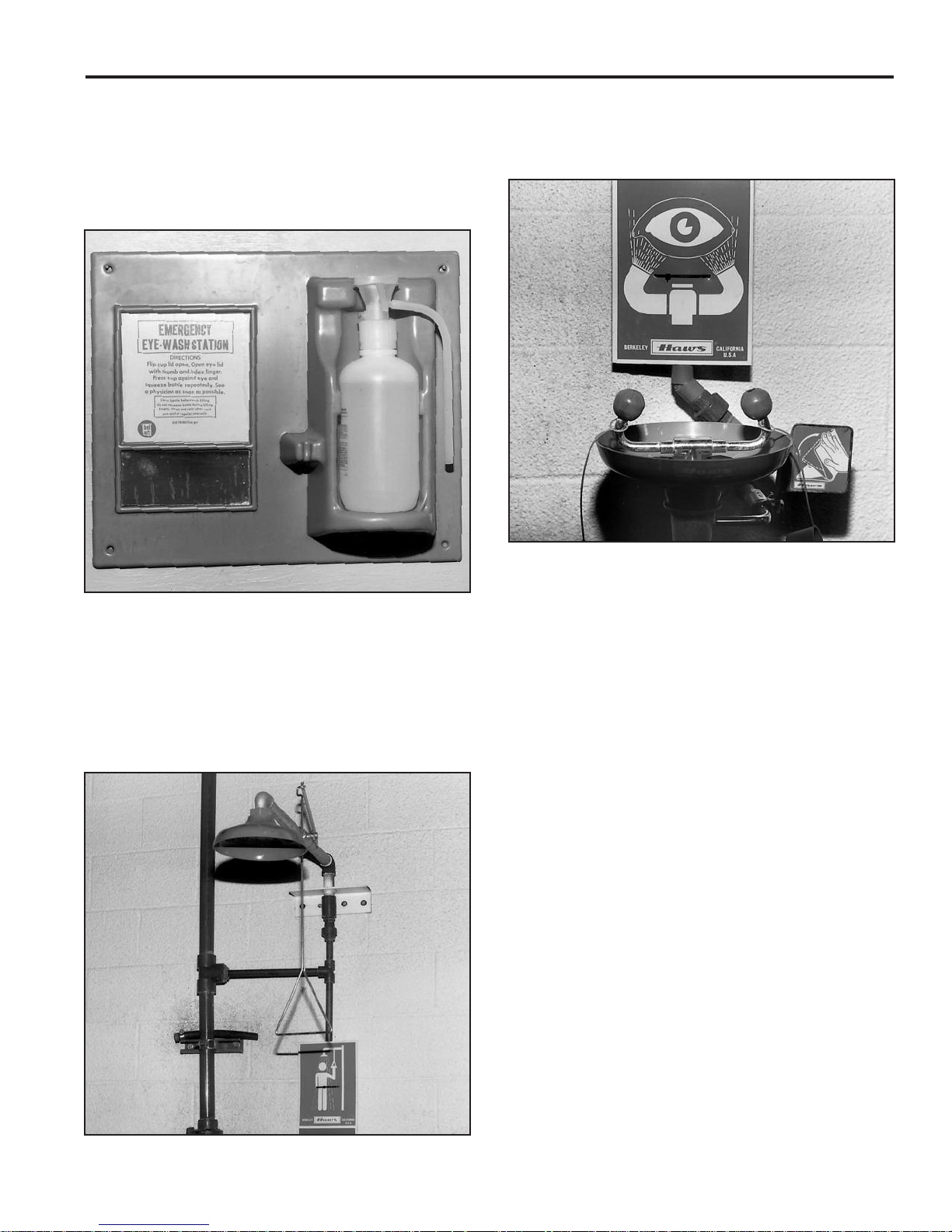
Eye Wash and Emergency Shower Facilities
Emergency eye wash and acid neutralization facilities should
be located in the immediate work area for easy access. The
three most popular types of eye wash and acid neutralizing
equipment are the chemical burn station, deluge shower, and
eye wash fountain.
2. A deluge shower (Fig. II-3) should be used where high spe-
cific gravity acid (above 1.400) is handled. The shower uses
a handle or foot treadle to turn on a powerful water stream
that can wash acid from skin and clothes.
Fig. II-2
1. A chemical burn station (Fig. II-2) is used in smaller bat-
tery charging and repair areas. The station consists of a
wall-mounted plastic squeeze bottle that contains a buffering solution for treating acid burns on skin, eyes and
clothing. This inexpensive equipment should be used only
where acid with a specific gravity lower than 1.400 is used.
A buffering or neutralizing agent shouldn’t be used in the
eyes without the approval of medical or safety personnel.
Fig. II-4
3. An eye wash fountain (Fig. II-4) should be used wherever
batteries and/or acid is handled, regardless of the acid’s
specific gravity. This device produces two streams of water
so that both eyes can be flushed simultaneously.
Neutralizing Acid and Electrolyte
For cleaning batteries, non-corrosive, water based battery
cleaning products are all that should be used. For user safety
and environmental regulatory compliance, the cleaning liquid
should contain no hazardous chemical ingredients. Even some
products labeled “Battery Cleaner” must be avoided because of
hazardous ingredients and damage to batteries and related
equipment.
Acid spills are common in battery rooms. When acid spills occur
it is critical to minimize:
1. Health and safety risk to personnel and the
environment.
2. Damage to batteries, equipment, and surrounding
surfaces.
3. Time to neutralize, absorb, and clean-up.
4. Disposal costs of waste materials.
5. Regulatory compliance risks and fines.
Fig. II-3
Neutralizing acid absorbers and spill kits have the performance
attributes required when dealing with acid spills. The ph neutral
dry and non-hazardous waste is easy to sweep-up and dispose
as non-hazardous waste.
11

SECTION II — BATTERY SAFETY (cont.)
1/4"
COVER VENT CAP IMPORTANT
Repairing Batteries
Keep in mind several safety points when repairing batteries:
1. Never work on a battery while on charge or discharge.
Always disconnect it from the charger or truck first.
2. Always remove vent caps before beginning work.
3. Always remove gas from all battery cells before beginning work (see Gas Purging — Section VI).
4. Use caution when melting sealing compound. Melted
compound is extremely hot and can cause severe
burns if not properly handled (see Sealing Compound
— Section VI).
SECTION III — INSTALLATION AND USE
Receiving a Battery
After receiving a battery, examine the crate and pallet for signs
of damage. If you see any wet spots, the battery may have
been tipped or damaged during transit. Be careful when handling a crate or packing material that’s contaminated with
spilled electrolyte. Chemical burns can result if skin or clothing
comes in contact with the spillage. Follow the precautions listed
under “Handling Acid” — Section II.
KEEP ELECTROLYTE LEVEL BELOW
FILLING WELL AS SHOWN
5. To prevent possible short circuits, use insulated tools
whenever you are working on a battery. If possible,
cover the terminals and connectors with an insulating
material such as plywood or heavy plastic, if the batte r y bei ng wo r ked on doe s not have inter cell
onnector and terminal shrouds installed.
c
For more detailed information on safety battery repair procedures, see Section VI — Battery Repair.
Temperature Effect on Specific Gravity
Temperature Loss of Specific Gravity
(Degrees Fahrenheit) Per Day
120 .004
100 .003
80 .001
50 .0005
a freshening charge (see “Placing a Wet Charged Battery in
Service”) should be given whenever the specific gravity falls
below 1.240 or every six weeks. If the average storage temperature is below 68°F (20°C), check the specific gravity at least
once every two months. If the temperature is above 68°F
(20°C), check it every month.
of New Batteries
Stored on Open Circuit
Maximum
Fig. III-1
Every cell should be inspected to be sure that the electrolyte
level is above the moss guard (Fig. III-1). If the electrolyte level
is slightly below the moss guard in any cell, it can be raised by
transferring a small amount of acid from higher level cells within
the battery by using a syringe or hydrometer.
If a large amount of liquid is required to raise the level, the cell
jar may be damaged. Inspect the packing material under the
tray for signs of leakage. All damaged components should be
inspected by your East Penn agent or representative.
Call your East Penn representative immediately. In the meantime, keep the damaged cell’s vent cap tightly in place and
protect the floor from acid leakage. Do not attempt to discharge
or charge the battery.
Temporary Storage
When it is fully charged and the electrolyte is at the proper
level, the battery can be stored for up to a year. It should be
stored in a cool, dry, well-ventilated area away from direct sunlight. If the battery must be stored for several months or longer,
Batteries in steel trays without covers should be covered with a
non-conductive material to protect them from dirt, moisture, etc.
A flat sheet of rigid plastic or plywood will work well. Do not
drape flexible plastic sheeting over batteries because it might
trap explosive gases underneath.
Note: If batteries must be stored for more than one year, consult the
manufacturer.
Placing a Wet Charged Battery in Service
Give a freshening charge to a new battery before putting it into
service. Charge the battery until the specific gravity and all cell
voltages have stabilized. The full charge specific gravity is
1.280 to 1.295 when temperature corrected to 77°F (25°C).
Ideally, the battery should be cool; less than 90°F (32°C), when
it’s installed in the vehicle. Check the manufacturer’s specifications for full charge specific gravity on high gravity battery
types.
When installing a battery, make sure that the battery compartment is clean, corrosion-free and the ventilation openings aren’t
obstructed or blocked off.
To lift the battery, use a lifting beam and an overhead hoist (see
“Lifting Batteries” — Section II). Set the battery securely in the
compartment and block it into position. Some vehicles have
adjustable clips for blocking the battery into place. The battery
should not be wedged tightly into the compartment because
clearance for expansion must be provided. However, clearance
can’t exceed 1/2” between the block or clip and the battery tray
(Fig. III-2).
12

SECTION III — INSTALLATION AND USE (cont.)
Operation of the Battery
There are several factors that effect the operation of the battery
concerning its ability to deliver capacity and life expectancy.
Many chemical reactions are effected by temperature, and this
is true of the reaction that occurs in a storage battery. The
chemical reaction of a lead-acid battery is slowed down by a
lowering of the electrolyte temperature that results in less
capacity. A battery that will deliver 100% of rated capacity at 77°
will only deliver 65% of rated capacity at 32°F. See Table 3-1,
F
for specific gravity and on charge cell voltage temperature correction.
Specific Gravity and On-Charge Cell Voltage
Temperature Correction
Fig. III-2
Be sure all vent caps are in place because electrolyte from
uncapped cells can corrode the tray and vehicle.
Placing a Dry Charged Battery in Service
Note: The activation of dry charged batteries is an involved process which should be handled by trained personnel. For a
thorough explanation, refer to East Penn’s “Procedure for
Activating Dry Charged Industrial Cells and Batteries,” which is
supplied with every dry charge battery.
A dry charged battery is a fully charged battery from which all
the electrolyte has been removed. Because it’s essential to
keep these batteries in the dry state until ready for use, they
should be stored in a cool, dry, low-humidity area with their vent
caps and protector cap and plugs tightly in place until ready for
use. When reactivated, install as described in “Placing a Wet
Charged Battery in Service.”
Cycling Characteristics
Every time a battery is discharged and then recharged it’s
called a cycle. An average battery lasts 1,500 to 1,800 cycles,
or 5 to 6 years. (Actual battery life depends on battery type, the
severity of use, and how the battery was maintained while in
service.)
EXCESSIVE HEAT will contribute greatly to reducing battery
life by corroding the positive grids and excessive gassing which
loosens active material in the plates, especially the positive
plate. Over charging is the most common contributing factor to
excessive temperatures and gassing in a battery. A properly
rated and matched charger will help to avoid the problem of
overcharging.
CONSISTENT UNDERCHARGING of a battery will gradually
run down the cells and result in one or more cells becoming
completely discharged before the others, and may become
reversed. Capacity and life expectancy are greatly reduced by
undercharging. Equalizing charges to return the cells to a normal condition should be part of a weekly maintenance schedule.
OVERDISCHARGING can also cause permanent damage to
the battery. Recharging is more difficult and more time consumin g . Oft en c ompl ete recha rge is not atta i ned and the
undercharged battery is placed into service. Consequently, it is
over discharged to a lower limit resulting in loss of capacity and
premature battery failure. Optimum battery life can be aided by
limiting the depth of discharge to 80% of its rated capacity.
A good battery maintenance program is necessary to protect
life expectancy and capacity of the battery. A more detailed discussion of battery maintenance can be found in Section IV of
this manual.
BATTERY CHARGING
As a battery discharges, the voltage normally drops slowly at
first and then more rapidly toward the end of the discharge.
Battery temperature, on the other hand, rises during discharge,
although the increase isn’t as high as it is during charging. The
amount of temperature increase depends on ambient temperature, ampere discharge rate, and the amount of heat dissipation
(which varies according to battery type).
To obtain maximum service life, batteries should be operated at
115°F (46°C) or lower, and they shouldn’t be discharged to
below 80% of rated capacity. Frequent over-discharging can
drastically shorten battery life.
One way to prevent over-discharging is to be sure that the
ampere-hour (A.H.) capacity rating of the battery is high enough
for the battery’s work load. The battery will over-discharge if its
workload exceeds its capacity. For heavy-duty applications, a
higher capacity battery — such as East Penn’s MAX POWR
battery — may solve frequent over-discharge problems. To
determine if a higher capacity battery is right for your needs,
contact your East Penn agent or representative.
Basic Charging Facts
Proper charging is essential for maximum battery life. In general, the proper charging rate for lead-acid batteries is any rate
which doesn’t produce temperature higher than 115°F (46°C),
and any rate which doesn’t cause excessive gassing.
When a discharged battery is initially placed on charge, it draws
a current equal or close to the charger’s maximum output. As
the battery’s voltage rises, the charger output should adjust to
the changing voltage to assure a safe, efficient charging rate
during all stages of the charge.
With today’s automatic start/stop charges, under and overcharging are virtual ly e limin ated. These “sma rt” charg es h ave
computerized control units that can determine when a battery is
fully charged and then automatically terminate the charge cycle.
For example: The charger delivers a “maximum” start rate of 20
amps per 100 A.H. of rated capacity. As the voltage rises to 2.37
volts @ 77°F (25°C) per cell, the gassing voltage of the battery is
held constant until the charge rate tapers down to 5 amps per
13
SECTION III — INSTALLATION AND USE (cont.)
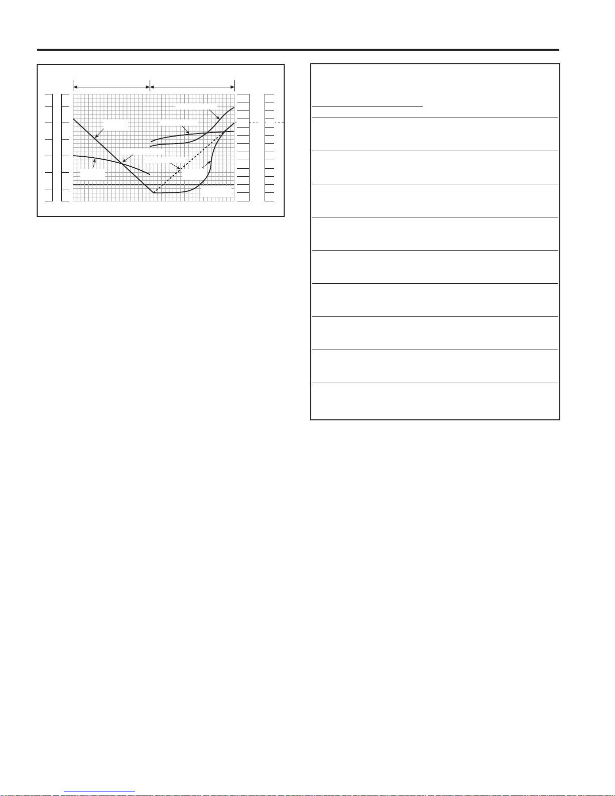
Typical Recharging Characteristics
TEMPERATURE
CELL VOLTS
2.80
2.60
2.40
2.20
2.00
1.80
1.60
140
120
100
80
60
4
0
2
0
%AMP. HOURS RETURNED
140
1
20
100
80
60
4
0
20
TIME
10
30
5
0
70
9
0
110
1
30
FULL CHARGE
DISCHARGE CHARGE
SPEC. GRAVITY
1.360
1
.340
1.320
1.300
1.260
1.240
1.220
1
.200
1.180
1.160
1.140
1
.120
1.100
1
.280
SPECIFIC
GRAVITY
VOL TS
PER CELL
A.H. DISCHARGED
A.H. RETURNED
TEMP ERA TURE
100%
DISCHARGE
SPECIFIC
GRAVITY
VOLTS PER CELL
Fig. III-3
100 A.H. This finish rate is held constant until the charger automatically shuts off. Charger start rates should not be more than
20 amps per 100 A.H. of rated capacity, and the finish rates not
less that 5 amps per 100 A.H. @ 2.60 V.P.C. (Fig. III-3).
The above requirements will return a discharged battery to full
recharge. See your East Penn representative for details.
Periodic inspection and adjustment of automatic charges
should be done by a qualified electrician.
Specific Gravity Temperature Correction
Specific gravity measurements are based on a cell temperature
of 77°F (25°C). In order to obtain an accurate specific gravity
measurement, the hydrometer reading must be adjusted based
on the temperature of the electrolyte. A good rule of thumb for
temperature correction is to add 4 points of specific gravity
(.004) for each 10 degrees Fahrenheit over 77°F and to subtract 4 points for each 10 degrees under 77°F.
Specific Gravity
Temperature Corrections
Electrolyte Specific On-Charge
Temperature Gravity Cell Voltage
Fahrenheit Celsius
Correction Correction
130 54 +.022 +.18
127 53 +.020 +.17
124 51 +.019 +.16
121 49 +.018 +.15
118 48 +.017 +.14
115 46 +.016 +.13
112 44 +.014 +.12
109 43 +.013 +.11
106 41 +.012 +.10
103 39 +.011 +.09
100 38 +.009 +.08
97 36 +.008 +.07
94 34 +.007 +.06
91 33 +.006 +.05
88 31 +.004 +.04
85 29 +.003 +.03
82 28 +.002 +.02
79 26 +.001 +.01
76 24 ——
73 23 -.002 -.01
70 21 -.003 -.02
67 19 -.004 -.03
64 18 -.005 -.04
61 16 -.006 -.05
58 14 -.008 -.06
55 13 -.009 -.07
52 11 -.010 -.08
Table 3-1
See table 3-1 — Specific Gravity Temperature Correction
Charging Methods
There are two important types of charge that are used for leadacid Industrial batteries: Standard Recharge (Cycle Charge)
and Equalizing Charge. (A third type of charge, the Freshening
Charge, is explained in “Placing a Wet Charged Battery in
Service”).
Standard Recharge — After a battery has undergone a normal
full shift and has been fully discharged to a recommended 80%
of rated capacity, it must undergo a complete, or standard,
recharge. Normally, a standard recharge is based on an 8-hour
charging cycle.
Equalizing Charge — Due to a slight difference in the construction of each battery cell, some cells take less charge than
others. An occasional equalizing charge will correct these cellto-cell imbalances and bring all cells up to the same capacity.
An equalizing charge is simply a 3-hour continuation of the
standard recharge at no more than the battery’s finish rate. A
minimum 3 amp per 100 A.H. equalize charge rate is necessary
to receive the full benefit of the equalize charge. A lower equalize charge rate will require a longer equalize charge period.
The best way to determine if the battery needs an equalizing
charge is to check the specific gravity readings for each cell. If
there is more than 0.020 specific gravity unit variation between
any two cells, the battery should be equalized. A good rule of
thumb is to equalize the battery once each week.
See table 3-2 — Specific Gravity vs. Percent Discharge
The Charging Process
During the charging process, the sulfate in the battery plates,
which accumulated during discharge, is driven back into the
electrolyte. This increases the specific gravity and brings the oncharge voltages up to 2.50-2.70 volts per cell, depending on the
age of the battery. (See “Discharging/Charging Characteristics”
in Section I).
As the battery approaches full charge, the charging rate must be
reduced to the battery’s finish rate. The finish rate is that current
which can be used safely on the battery anytime charging is
required, and which can be continued after the completion of the
charge without causing excessive gassing or high temperatures.
East Penn’s official finish rate in amps is equal to 5% of the amp
hour capacity at the 6 hour rate. The finish rate is on the nameplate of all East Penn batteries.
Normally, a battery will be properly charged if the charging
equipment is in good working condition and the battery is
“healthy”. A fully charged battery will have the following characteristics while on charge:
14
• Stable on charge battery voltage
• Gassing freely
• Charger current readings have leveled off
to finish rate
• Temperature-corrected specific gravity has
stopped rising
See table 3-1 for specific gravity temperature corrections.

SECTION III — INSTALLATION AND USE (cont.)
ELECTROLYTE SPECIFIC GRAVITY
VS. PERCENT DISCHARGE
GRAVITY
PERCENT DISCHARGED
020406080100
1.100
1.120
1.130
1.140
1.150
1.160
1.170
1.180
1.200
1.220
1.240
1.250
1.260
1.270
1.280
1.290
1
.300
D45 - D55
D35 - D65
D75 - D150
H80
H120
D110
M75
D160
D85 - D100
M85
D125
ELECTROLYTE SPECIFIC GRAVITY
VS. PERCENT DISCHARGE
G
RAVITY
PERCENT DISCHARGED
020406080100
1.100
1.120
1.130
1.140
1.150
1.160
1.170
1.180
1.200
1.220
1.240
1.250
1.260
1
.270
1
.280
1.290
1
.300
P49 - P60
P38 - P22
P82 - P165
P121
P170
1.310
1
.320
1
.325
P95 - P110
P140
D and M Series MAX POWR Series
Table 3-2
15

SECTION III — INSTALLATION AND USE (cont.)
Improper Charging
Improper charging reduces battery capacity and life.
Undercharging can cause residual sulfation to remain on plates,
educing cell performance. Sulfation also slowly occurs when
r
batteries are stored for months without receiving periodic freshening charges. The cells of a sulfated battery give low specific
gravity and voltage readings. It’s difficult to bring a heavily sulfated battery back to full charge and doing so will develop high
temperatures. (See “Correction of Sulfated Cells” — Section IV).
Undercharging also results in insufficient gassing, which creates
a high acid content at the bottom of the cell, eventually leading
to sulfation on the bottom part of the negative plates. This condition can be corrected by periodic equalizing charges.
Although all batteries are overcharged to an extent during every
charge cycle, severe overcharging results in excessive gassing
and very high battery temperatures — both of which are damaging to the battery. Battery temperatures should not exceed
115°F (25°C) during charging.
Excessive gassing occurs when a high charging rate is continued after the battery has been brought to its gassing voltage
(2.37 volts per cell nominal). A noticeable bubbling of electrolyte
can be seen, accompanied by high electrolyte temperature.
Because the gas is released from the electrolysis of water,
excessive gassing results in unusually high water usage. (See
the Troubleshooting Chart at the end of Section IV for additional
causes and remedies.)
For reduced maintenance and long, trouble-free battery life,
make sure all your batteries are properly charged. If you’re having trouble correcting any problems, contact your East Penn
agent or representative.
Charging Safety
There are several important safety precautions that should be
taken when charging a battery:
• Do not use open flames when checking the electrolyte
levels in storage batteries.
• Keep all open flames, sparks and matches away from
the charging area. DO NOT SMOKE around the charging
area.
• Only properly trained personnel should charge batteries.
• Before a battery is removed from a truck, or charged in a
ruck, the truck’s electrical circuit should be open, the
t
battery should be unplugged from the truck, and the
wheels should be chocked. (If removing the battery from
the truck, be sure to use proper lifting methods and
equipment.)
• The charger should be OFF before connecting it to the
battery.
• All mechanical connections on the battery and charger
should be tight. Loose connections can overheat and
cause arcing that could cause a gassing cell to explode,
or cables to become hot to the touch.
• Covers on battery trays should be kept open while
charging to promote cooling and allow gas to escape. If
the battery remains in the truck during charging, keep
the battery compartment cover and battery tray cover
open.
• Vent plugs should be kept firmly in place at all times to
minimize electrolyte spray when the battery gasses.
• The charger should be OFF before disconnecting the
battery.
• The charger connector shall not be plugged into the lift
truck connector under any circumstances.
SECTION IV — BATTERY MAINTENANCE AND TROUBLESHOOTING
Proper maintenance is essential to obtain long life and maximum efficiency from any Industrial battery. Carefully following a
scheduled maintenance routine will help increase battery performance and prolong service life.
One of the keys to an effective battery maintenance program is
to maintain an accurate records system of battery cycles and
maintenance/repair work for each battery. A records system is
particularly important for operations that use a large number of
batteries.
If you don’t already have one, these procedures should help
you create a reliable records system:
1. Assign a code/identification number to each battery and
charger. Use a multiple digit-system if you have several
different sizes or types of batteries. Prefixes or suffixes
can be used to identify batteries by size, voltage, shift,
lift truck, etc.
2. Designate a “pilot cell” for each battery. Record the specific gravity, voltage and temperature of the pilot cell
when the battery is first received and equalized, and
before and after each charge. The readings taken on
the pilot cell are considered to represent the specific
gravity, voltage and temperature of all the cells. Always
use the same cell for the pilot cell. The pilot cell
should be positioned near the center of the battery and
can be identified with a marking of some sort on the
intercell connector shroud or cell cover.
3. At least once each month, measure and compare the
specific gravity of all the cells. The readings should be
uniform from cell to cell. If the specific gravity readings
fall 20 points (0.20) below the nominal specific gravity
reading of 1.290, the electrolyte levels should be
checked and brought up to a uniform level before checking for a second time. If, at any time, the readings are 20
points (.020) greater than the nominal specific gravity
readings of 1.290, or the range of the on-charge cell
voltage readings is more than 0.15 volts, the battery
could be showing signs of cell failure. Contact your
authorized Deka Service Representative.
4. Remember to accurately record the number of cycles,
specific gravity, temperature and voltage readings; and
all maintenance and repair information for every battery.
THE DAILY BATTERY RECORD (Fig. IV-1) is an example of a basic record-keeping form. You should use a
form that best fits your operation’s individual needs. It is
also recommended that the identification number of the
charger used to charge the battery be recorded.
16

SECTION IV — BATTERY MAINTENANCE AND TROUBLESHOOTING (cont.)
DAILY BATTERY RECORD
Battery Number
Month Year
Total Cycles
Date
Specific Gravity
In Out
Operator
Wate r
Added
Repairs and Capacity Tests
(Date, Description and Results)
The correct hydrometer reading corresponds to an imaginary
line drawn across the side of the barrel at the lowest level of the
electrolyte. If the hydrometer has to be removed from the vent
hole, pinch the nozzle tightly or place a gloved finger against
the opening to prevent dripping.
To take the temperature reading, use the thermometer that’s
built into the hydrometer. If your hydrometer doesn’t have one,
insert a thermometer into the electrolyte of the cell. If the ther-
ometer doesn’t have specific gravity/temperature corrections
m
marked on it, refer to the temperature correction chart (Table 3-
1 — Section III). Always make sure the corrections on the float
thermometer agree with the chart in this service manual.
To obtain an accurate gravity measurement, it is important to
temperature correct the reading, as all specific gravity readings
should be corrected to a standard temperature of 77°F for proper comparison.
In addition to providing records of tests, repairs and individual
performance for each battery, accurate record keeping can also
reveal other helpful information:
• Specific gravity records taken at the beginning and
end of each cycle can pinpoint any irregularities in the
battery’s condition or in its operation. Readings taken
before recharging can indicate possible over-discharging and use in a low voltage condition, which eventually
can cause damage to lift truck electrical components
and shorten battery life.
• Maintenance and repair records can also point to bat-
tery abuse as well as help gauge individual battery
performance.
• Monthly and yearly records indicate the battery’s cycle
“age” and assist in controlling inventory and replacement
programs.
Fig. IV-1
Fig. IV-2
Using a Voltmeter
Using a voltmeter to measure open circuit voltage is usually a
faster and easier way to check a battery than measuring specific gravity with a hydrometer. A voltmeter is also used when
on-charge or on-discharge voltage readings are needed.
For individual cell voltage readings, place the positive lead of
the voltmeter on the positive terminal of the cell and the negative lead of the voltmeter on the negative terminal of the same
cell (Fig. IV-3).
After measuring the voltage of every cell, take the specific gravity readings of the cell with the highest open circuit voltage and
the cell with the lowest open circuit voltage. The specific gravity
readings should confirm the state of charge of both cells and
accurately pinpoint the difference between them. If the specific
gravity difference is greater than 20 points, a problem might
exist with one of the cells. Also, a cell may have internal problems if the open circuit voltage is more than 0.03 volts below
the average voltage of all the cells.
Reading Hydrometers and Thermometers
To take a specific gravity reading, remove the cell’s vent cap,
place the rubber hydrometer nozzle into the vent opening and
draw enough electrolyte into the barrel to permit the float to rise
freely. Hold the hydrometer at eye level as shown in (Fig. IV-2).
Battery Inspection
Batteries should be inspected periodically to avoid damage
resulting from previously undetected problems or improper
maintenance and operational procedures.
17
 Loading...