

de Jong Duke Zia 6000 series, Zia 8000 series, 9CND Series Technical Manual

Zia 6000 and 8000
series
Technical manual
Model: Zia 6000 and Zia 8000
Machine type: 9CND…
Revision 1.0, English
Reference: 5DTCNP20
The manufacturer of the machine is:
De Jong Duke
Postbus 190
3360 AD SLIEDRECHT
The Netherlands
Telephone +31 (0) 184 496767 www.dejongduke.nl
Fax: +31 (0) 184 416059 support@dejongduke.nl

2
Copyright © 2014, J.M. de Jong Duke automatenfabriek b.v.
All rights reserved.
Although this user manual has been put together with the utmost care, J.M. de
Jong Duke automatenfabriek b.v. accepts no liability for inaccuracies or
omissions. No liability is accepted for the consequences arising from operation of
the equipment in accordance with the information contained in these instructions.
J.M. de Jong Duke automatenfabriek b.v. reserves the right to alter specifications
at any time and without prior notification to the purchaser.
Preface
This technical manual is valid for the machine supplied by the manufacturer,
including the options installed by the manufacturer. The manufacturer accepts no
liability for any damage resulting from incorrect or improper use of the machine,
or resulting from modifications that have not been authorized by the
manufacturer.
This manual gives instructions for the operation and maintenance of the machine.
Moreover, it gives solutions to simple malfunctions that may occur. The
instructions in some paragraphs are meant only for persons who are trained in
the operation and maintenance of the machine.
Always use original parts from the manufacturer when the machine needs to be
repaired.
Carefully read this technical manual before you operate and/or repair the
machine.
Keep this manual in a safe place for possible later reference.
Only properly trained personnel may carry out repairs, install the machines or
transport the machines.
This manual cannot be regarded as a replacement for training and instruction, but
must be seen as an addition to the training, and as a reference work.

3
CONTENTS
1 SAFETY ............................................................................................... 6
1.1 SAFE USE .......................................................................................... 6
1.2 SAFETY RISKS ..................................................................................... 6
1.3 INSTALLATION..................................................................................... 6
1.4 MAINTENANCE .................................................................................... 6
1.5 EXTENDED DOWN TIME .......................................................................... 7
2 DESCRIPTION OF THE MACHINE ......................................................... 8
2.1 GENERAL........................................................................................... 8
2.2 THE FRONT OF THE MACHINE .................................................................... 8
2.3 OVERVIEW OF THE MACHINE INTERIOR ........................................................ 8
2.4 BACKSIDE OF THE MACHINE ..................................................................... 9
3 OPTIONS AND ACCESSORIES ............................................................ 10
3.1 BASE CABINET .................................................................................. 10
3.2 CUP DISPENSER ON FRONT .................................................................... 10
3.3 CUP DISPENSER ON RIGHT HAND SIDE ....................................................... 10
3.4 TABLE BETWEEN MACHINE AND CABINET .................................................... 10
3.5 COLD WATER UNIT IN BASE CABINET ......................................................... 11
3.6 WASTE GUIDE ................................................................................... 11
3.7 DRIP TRAY DRAIN. .............................................................................. 11
3.8 FRESH MILK SYSTEM............................................................................ 11
3.9 PAYMENT SYSTEMS ............................................................................. 12
3.10 MECHANICAL CONSUMPTION COUNTER ....................................................... 12
3.11 PUMP SET ........................................................................................ 12
4 TECHNICAL DATA .............................................................................. 13
4.1 TYPE PLATE ...................................................................................... 13
4.2 TECHNICAL SPECIFICATIONS .................................................................. 13
4.3 DIMENSIONS OF THE MACHINE ................................................................ 14
4.4 WATER SPECIFICATIONS ....................................................................... 15
4.5 MACHINE CONFIGURATIONS AND VARIATIONS .............................................. 15
4.6 NORMS AND STANDARDS ...................................................................... 15
5 FUNCTION OF THE COMPONENTS ..................................................... 16
5.1 HOT WATER SYSTEM ............................................................................ 16
5.2 SCHEMATIC DIAGRAM OF THE WATER SYSTEM .............................................. 17
5.3 INLET VALVE ..................................................................................... 18
5.4 PRESSURE REDUCER ............................................................................ 18
5.5 WATER FLOW METER/WATER COUNTER ...................................................... 20
5.6 PUMP ............................................................................................. 21

4
5.7 BOILER ........................................................................................... 23
5.8 POSITION OF VALVES IN THE HOT WATER SYSTEM .......................................... 26
5.9 2-WAY VALVE / OUTLET VALVE ................................................................ 28
5.10 3-WAY VALVE / BREWER VALVE ............................................................... 29
5.11 PRESSURE VALVE 2 BAR ....................................................................... 30
5.12 SAFETY PRESSURE VALVE 12 BAR ............................................................ 30
5.13 COEX
®
BREWING SYSTEM .................................................................... 31
5.14 REMOVAL OF THE COEX
®
BREWER ........................................................... 32
5.15 INSTALL THE BREWER .......................................................................... 33
5.16 BREWER CYCLE .................................................................................. 34
5.17 BREWER MOTOR AND MICRO SWITCH ........................................................ 36
5.18 UPPER PISTON .................................................................................. 37
5.19 CONTROLLING COFFEE/ESPRESSO PRESSURE SWITCH ..................................... 38
5.20 SEALS ............................................................................................ 40
5.21 REPLACE SEALS IN LOWER PISTON ........................................................... 41
5.22 MIXER ............................................................................................ 42
5.23 GRINDER ........................................................................................ 46
5.24 GRINDER IN DOOR .............................................................................. 47
5.25 REMOVING BEAN CANISTER AND GRINDER. ................................................. 47
5.26 GRINDING ADJUSTMENT. ...................................................................... 48
5.27 DEFAULT GRINDER SETTING ................................................................... 49
5.28 INGREDIENT CANISTERS ....................................................................... 50
6 ELECTRONIC HARDWARE .................................................................. 51
6.1 POWER SUPPLY .................................................................................. 52
6.2 CONTROL BOARD ............................................................................... 53
6.3 I/O BOARD ...................................................................................... 54
6.4 CONNECTORS ON THE IO BOARD ............................................................. 55
6.5 LVDS DISPLAY AND TOUCH SCREEN. ........................................................ 57
6.6 SPEAKER ......................................................................................... 57
6.7 CUP SENSOR .................................................................................... 58
6.8 ELECTRICAL SCHEMATICS ...................................................................... 59
7 SERVICE AND PROGRAMMING .......................................................... 61
MODE WITHOUT PASSWORD ........................................................................... 61
7.1 INSERTING SAFETY KEY ........................................................................ 61
7.2 FUNCTIONS WITHOUT PASSWORD ............................................................ 62
7.3 SERVICE MODE WITH PASSWORD ACCESS ................................................... 64
7.4 RECIPE SETTINGS ............................................................................... 65
7.5 BOILER TEMPERATURE ......................................................................... 68

5
7.6 CUP SENSOR .................................................................................... 69
7.7 LANGUAGE ....................................................................................... 69
7.8 PAYMENT SETTINGS ............................................................................ 70
7.9 SOFTWARE CONFIGURATIONS ................................................................. 71
7.10 LOAD PERMISSIONS ............................................................................ 72
7.11 CLOCK/TIME SETTINGS ........................................................................ 73
7.12 JUG SETTINGS ................................................................................... 74
7.13 IMAGES .......................................................................................... 75
7.14 TEST OUTPUTS .................................................................................. 76
7.15 SHOW ERROR LOG .............................................................................. 76
7.16 ERROR SETTINGS ............................................................................... 77
7.17 WATER FILTER SETTINGS ...................................................................... 78
7.18 RINSE ............................................................................................ 78
7.19 WEAKLY CLEANING CYCLE BREWER ........................................................... 78
7.20 SHOW PRODUCT COUNTERS ................................................................... 78
7.21 SOFTWARE INFORMATION ..................................................................... 78
7.22 SHOW EVA-DTS ............................................................................... 79
7.23 CHANGE THE SERIAL NUMBER ................................................................. 81
7.24 FAN TURN OFF DELAY ........................................................................... 81
7.25 EMPTY BOILER ................................................................................... 82
8 HOW TO DO ...................................................................................... 83
8.1 HOW TO LOAD A NEW CONFIGURATION FILE FROM AN USB STICK? ..................... 83
8.2 HOW TO LOAD A NEW FLASH(SWF) OR MOVEC ICEQ FILE FROM USB ................ 84
8.3 HOW TO GET AND LOAD A PERMISSION KEY ................................................. 85
9 WARNING, FAILURE AND ERROR MESSAGES .................................... 89

1 Safety
1.1 Safe use
Before using your coffee machine, please read the safety
instructions and all of the information in this manual first and
keep it for future reference.
Be careful! This machine serves hot drinks. Don’t reach
beneath the dispensing nozzles and hot water spout after
selection and during dispensing.
This appliance can be used by children aged 8 years and
above and persons with reduced physical, sensory or mental
capabilities or lack of experience and knowledge if they have
been given supervision or instruction concerning use of the
appliance in a safe way and they understand the hazards
involved. Children shall not play with the appliance. Cleaning
and user maintenance shall not be made by children without
supervision.
The machine may only be in locations where it can be
overseen by trained personnel.
1.2 Safety risks
The most important safety risks during maintenance of this
machine:
Moving parts inside the machine, beware of trapped fingers if
the service key is placed when the door is open.
Beware of hot parts and hot liquid inside the machine, even
after the power is disconnected.
1.3 Installation
Installation, transportation and adjustment of the machine
should only be carried out by properly trained service
personnel.
Check the appliance for transport damage. Do not connect a
damaged machine.
The machine is not suitable for outdoor use.
Do not install the machine in an area where a water jet or
similar device could be used.
Place the machine on a level surface in a hygienic dry room,
with a temperature between 5°C and 35°C. (40°F - 95°F)
Do not use an extension cord.
Only hose-sets according to IEC 61770 may be used for the
connection to the water supply.
1.4 Maintenance
Regular cleaning according to the user manual is needed to
ensure hygienic operation.

7
The appliance shall not be cleaned by a water jet.
Do not use water in or near the machine unless the
instructions explicitly give direction to do so.
Do not use aggressive cleaning products or abrasives to clean
(parts of) the machine.
1.5 Extended down time
If the machine will not be used for a longer period of time (for
example during the holidays) it is recommended to switch off
the water supply and the electricity. The main on/off switch
(see picture in chapter 2.3, point 2) is located at the inside of
the machine.
In areas where the temperature can fall below freezing, the
boilers must be emptied. (see chapter 7.25)
8
2 Description of the machine
2.1 General
The machine is a compact semi-automatic machine for the preparation and
vending of hot and optional cold drinks.
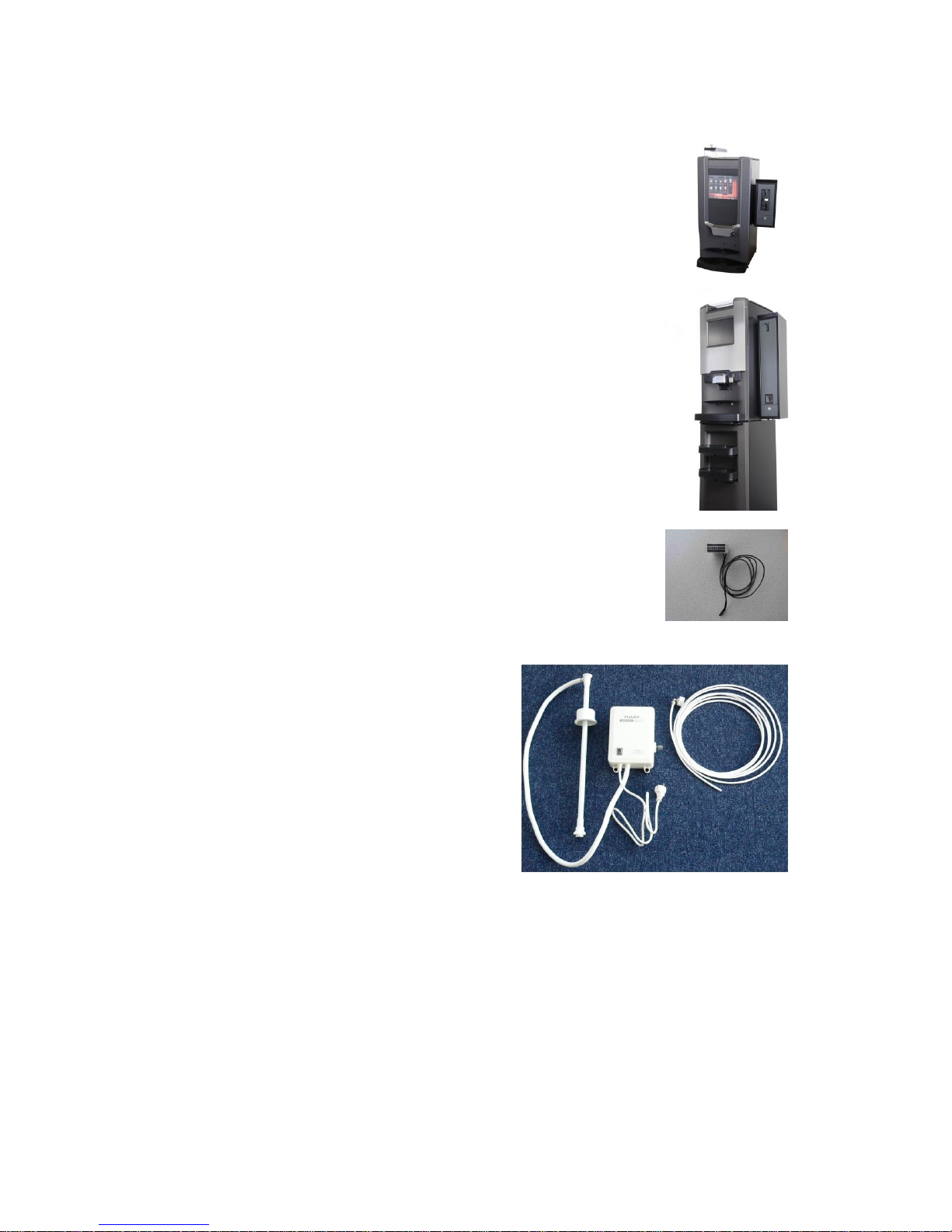
2.2 The front of the machine
The machine can be operated by using the touch panel on the door. By touching
one of the selection images on the screen, a product choice can be made.
Before pressing start, first a cup must be placed under the correct dispense
nozzle.
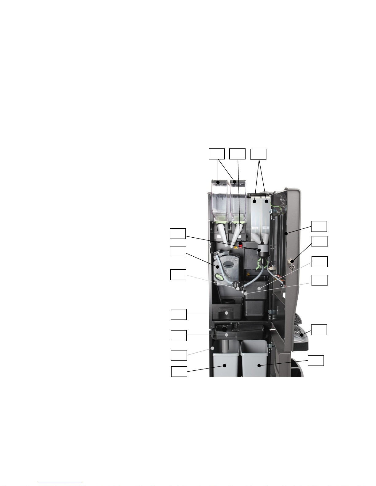
2.3 Overview of the machine interior
1. Bean canisters
2. On/off switch
3. Instant canisters
4. Door switch
5. Door lock
6. Waste guide (or Waste bucket)
7. External drip tray
8. Internal drip tray.
9. Dispensing nozzles
10. CoEx® brewer system
11. Mixing system
12. Base cabinet (Option)
13 Waste bucket sensor
14 Waste (residue) bucket
in base cabinet. (Option)
15 Waste (liquid) bucket
in base cabinet. (Option)
2 1 3 5 6
10
11
13
4
9
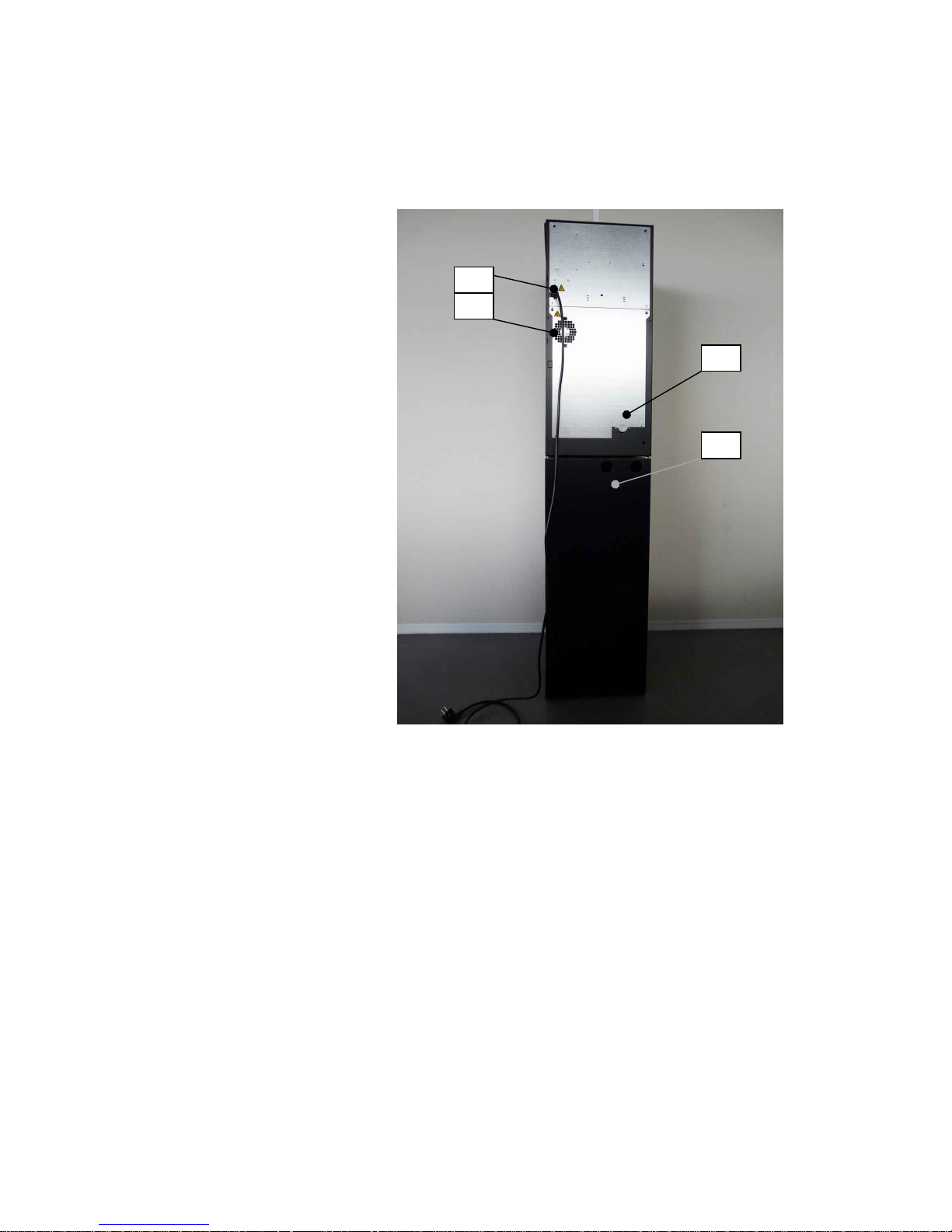
2.4 Backside of the machine
1 Water connection
2 Holes for water filter in
base cabinet. (optional)
3 Fan
4 Power cord
4 1 2
10
3 Options and accessories
The machine can be extended with several options. Some options can
interference or exclude other options.
3.1 Base cabinet
Part number 9OKNK1140 is a base cabinet with condimental trays.
Part number 9OKNK1110 is a base cabinet with closed front.
Dimensions base cabinet:
Height: 850 mm / 33.5 inch
Width: 360 mm / 14.2 inch
Depth: 510 mm / 20.0 inch
3.2 Cup dispenser on front
A Cup dispenser can be mounted on the front of the base cabinet
instead of an ingredient tray.
Part number 9BEB008 for cups 70mm diameter
Part number 9BEB010 for cups 80mm diameter
3.3 Cup dispenser on right hand side
Part number 9BEB007 for cups 70mm diameter
Part number 9BEB009 for cups 80mm diameter
3.4 Table between machine and cabinet
A table can be mounted in-between the base cabinet
and machine
Part number 9ETA003 table for 70mm cups
Part number 9ETA005 wide table for 70mm cups
Part number 9ETA007 table for 80mm cups
NOTE:
The drain from the drip tray to a bucket in the base
cabinet is not possible in combination with this option.
11
3.5 Cold water unit in base cabinet
A cold water unit for chilled water or a unit for
carbonated and chilled water can be installed in the
base cabinet.
Part number 9VKS019 chiller for chilled water.
Part number 9VKS017 chiller for chilled and
carbonated water.
3.6 Waste guide
The machine can be extended with a waste guide to the base
cabinet.
Part number 5KAF085
If this waste guide is installed, the error and warning
messages based on number of cycles needs to be switched off
(Set to not available) in the service menu.
(see chapter 7.16, error settings)
In this case the wires on the waste bucket sensor needs to be
electrical disconnected.
3.7 Drip tray drain.
The water from the drip tray can be drained to a large bucket in the base cabinet.
This drain is only available in combination with a base cabinet.
An extra sensor can be installed in the base cabinet for detecting a full bucket.
Part number 9AOV011
3.8 Fresh milk system.
It is possible to provide the machine with a fresh milk system.
This must be done in the factory, it is not possible to build a fresh milk system in
an existing machine.
For information, contact the manufacturer: support@dejongduke.nl
12
3.9 Payment systems
A Coin validator in a side unit.
A coin validator/acceptor communicating via the MDB protocol
can be connected to the control board.
B Change giver in a side unit.
A coin change giver, communicating via the MDB protocol,
can be connected to the control board.
C Card reader in a side unit.
A card reader or key payment system, communicating via the
MDB protocol, can be connected to the control board.
3.10 Mechanical consumption counter
A total product counter can be installed in the door and is
connected to the control board.
Part number 5ETL010
3.11 Pump set
The Machine can work in combination with a
pump set.
Part number of the 230V pump set complete:
9VIL018

13
4 Technical data
4.1 Type plate
The type plate is mounted at the inside of the machine, at the top left.
The type plate shows:
- Manufacturer
- Serial number
- Type/model specification
- Power connection
- Date of production
- Water connection
4.2 Technical specifications
Dimensions:
Width 360 mm / 14.2 inch
Depth 510 mm / 20.1 inch
Height :
- Standard machine: 795 mm / 31.3 inch
- With bean canister: 875 mm / 34.5 inch
- With increased bean canister: 1025 mm / 40.4 inch
Weight (empty): ±50 kg / 110 lbs
Electrical connection possibilities:
- 120 VAC, 60 Hz, 1.3 kW
- 220-240 VAC, 50-60 Hz, 2.9 kW
- 220-240 VAC, 50-60 Hz, 1.5-1.8 kW (limited power setting)
Water line pressure:
- Minimum 100 kPa (1 bar)
- Maximum 600 kPa (6 bar)
- Rated pressure: Water boiler 1.1 MPa (11 bar)/160 psi
Steam boiler 0.5 mPa (5 bar)/ 72 psi
Capacity waste bucket:
About 180 coffee consumptions.
Noise level:
- Standby: 0 dB(A).
- During delivering beverages using whole beans: < 63 dB(A).
Ambient temperature:
- Storage 5 - 50°C (40 - 120°F)
- Operating 5 - 35°C (40 - 95°F)
14
4.3 Dimensions of the machine
The machine can be extended with several options.
In the pictures below are the dimensions for a standard sized machine.
Door lock
Front view
Top view
795mm
31.3 inch
170mm
6.7 inch
295mm
11.6 inch
360mm
14.2 inch
170 mm
6.7 inch
160mm
6.3 inch
350mm
13.8 inch
80mm
3.2 inch
lid
door
50 mm
2 inch

15
4.4 Water specifications
Water line pressure: See chapter 4.2
The water flow rate from the mains should be minimal 2,5 liter per minute.
For an optimal operating of the coffee machine and an optimal coffee quality, the
water should be conform the following specifications:
- Hardness: 6-8 ºdH (German hardness) or11-14 °fH (French hardness)
- pH value: Minimal 6.5
Maximal 8.0
- Conductance: about 100S (micron Siemens) @ 20º C (68º F)
A water filter can be used if the water quality is not conform our specification.
The incoming water temperature may not be above 30ºC. (86ºF)
4.5 Machine configurations and variations
The machine can be equipped in different canister and product variations. The
specification number is always printed on the type plate. See the product
information sheets for detailed information.
www.dejongduke.nl
4.6 Norms and standards
The machine bears the CE marking and complies with the following
directives/regulations:
2006/42/EC Directive on machinery
2006/95/EC Low voltage directive
2004/108/EC Directive EMC
(EG) 1935/2004 Regulation on food contact materials
98/83/EG Directive on the quality of water
2011/65/EU Directive ROHS
The machine complies with the following standards:
IEC 60335-1 Safety of household and similar appliances
IEC 60335-2-75 Particular requirements for dispensing appliances and
vending machines
EN 61000-6-3 Radiated and conducted immunity up to 1 GHz
EN 61000-6-1 Radiated and conducted immunity up to 2.7 GHz
EN 61000-4-2 ESD
EN 61000-4-3 HF immunity
EN 61000-4-4 EFT
EN 61000-4-5 Surge
EN 61000-4-6 CDN/clamp injection
EN 61000-4-8 Power Magnetic filed
EN 61000-4-11 Dips and voltage fluctuations
EN 61000-3-2 Harmonic currents
EN 61000-3-3 Flicker
16
5 Function of the components
In the next paragraphs you find a detailed description of the several parts and
components in the machine.
Understanding of the function of the different components is essential for
maintaining the machines.
5.1 Hot water system
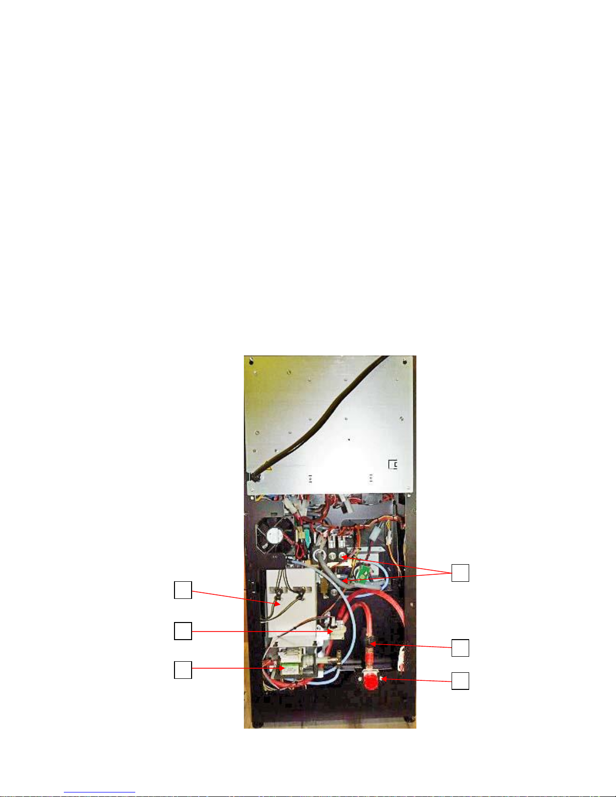
The water system is positioned at the back side of the machine and accessible
from the back.
If water and power are connected and the door is closed the water system start
filling the boilers automatically.
The water system consists out of the following main components:
1. Inlet valve
2. Pressure reducer
3. Flow meter
4. Vibration pump(s)
5. Boilers
6. Valves (outlet valves and pressure valves)
4
17
5.2 Schematic diagram of the water system
(standard 9CND machine, 2 mixers)
Mains water
Pressure
reducer 0,9 bar
C
Pump 1
Pressure
valve 2 bar
3-way
outlet
valve
Drip tray
Temperature
and level
sensor
Boiler with
heater
Mixer
Hot
water
2-way outlet
valve
Expansion
valve
Flow meter
Pump 2
Brewer
Mixer
2
1 2 1
2
1
2
1
2
1
Safety
pressure
valve 12 bar
Boiler 1
Boiler 2

18
5.3 Inlet valve
The inlet valve is controlled by the level sensor in the
boiler and is switched on during a dispense of hot water
to the brewer or mixer. The inlet valve is a 24V DC
valve. The inlet valve contains a backflow protection.
This backflow protection is preventing that water is
flowing back into the water supply.
Electrical connections/wire colors:
Number
Wire color
function
1
Orange
Common (+24V)
2
Orange-green
Output (0)
5.4 Pressure reducer
The pressure reducer reduces the water pressure to a stable pressure
independent from the inlet pressure from the mains water supply.
The required inlet pressure from the water supply is between 1,0 and 6 bar.
The pressure reducer is adjusted to an outlet pressure of about 0,8 - 0,9 bar
during an espresso cycle.
The input and output tube to the reducer must
be connected in the right direction, the reducer
works incorrectly in the reversed mode.
There is an arrow on the side of the reducer
indicating the correct water flow direction.
The reducer contains a backflow protection. This
backflow protection prevents the possibility that
water from the machine is flowing back into the
main water supply.
19
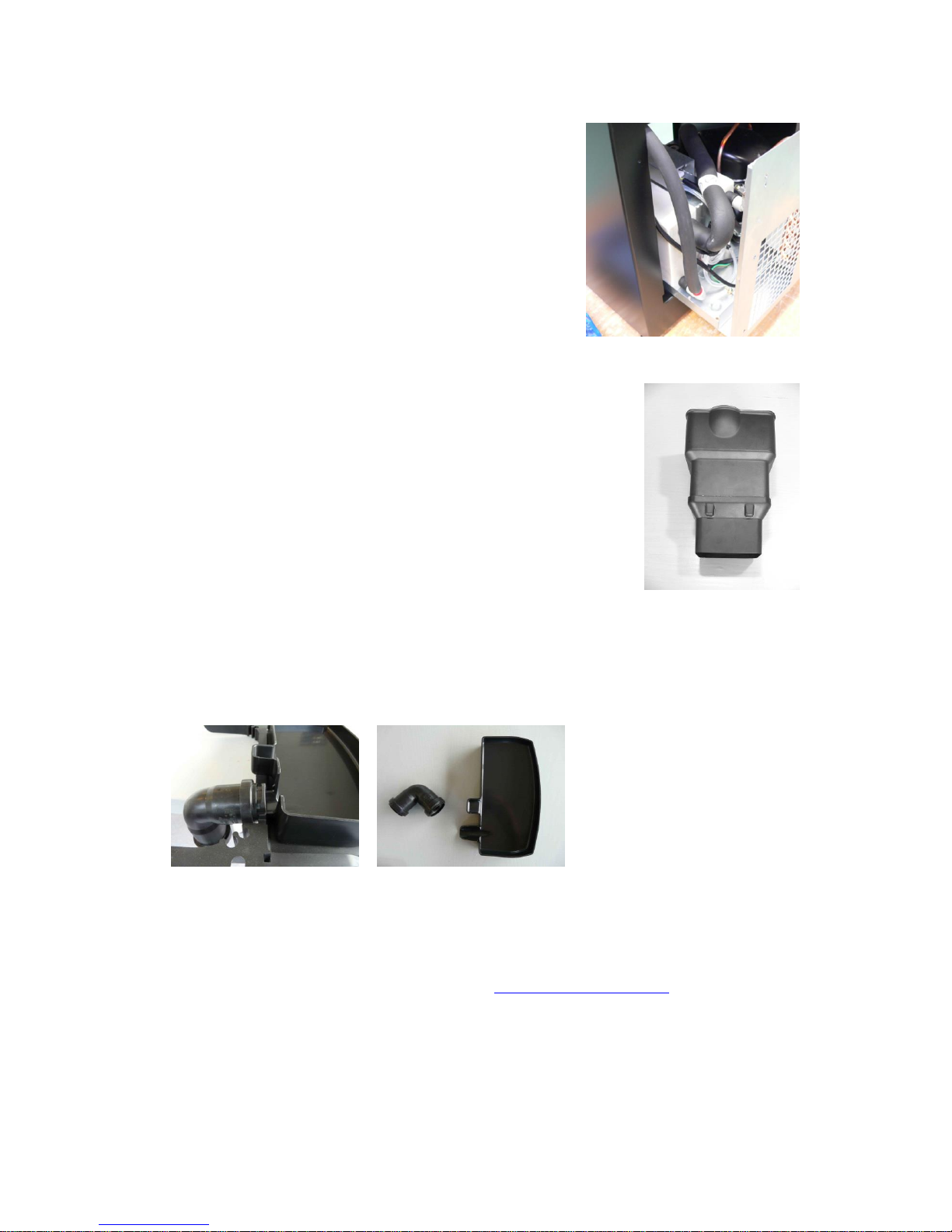
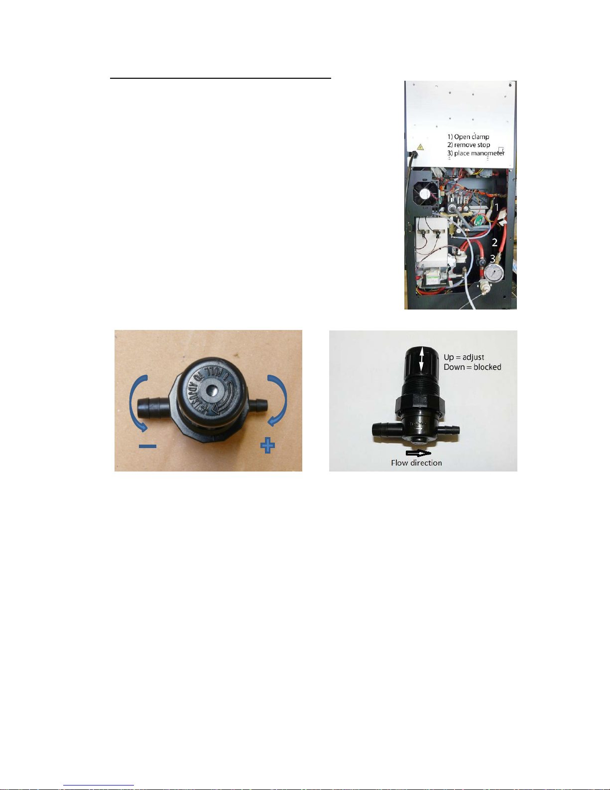
Procedure to adjust the pressure reducer:
1. Remove the lower back plate from the machine.
2. Remove the tube clamp and stop. (see picture)
3. Connect the manometer to the tube.
4. Pull out the knob to unlock the reducer.
5. Select an (double) espresso. Adjust the reducer by
turning the knob during the pump cycle of the espresso
selection. The manometer must show 0,8 - 0,9 bar during
an espresso cycle.
6. Lock the reducer by pushing the knob down towards it’s
own housing.
7. Disconnect the manometer and replace the tube clamp
and stop in the tube.
8. Replace the back plate on the machine.
9. Ready
Part number pressure reducer: 4MVL010
Looking from above: Turning clockwise = increase output pressure
Turning counter clockwise = decrease output pressure
20
IN
OUT
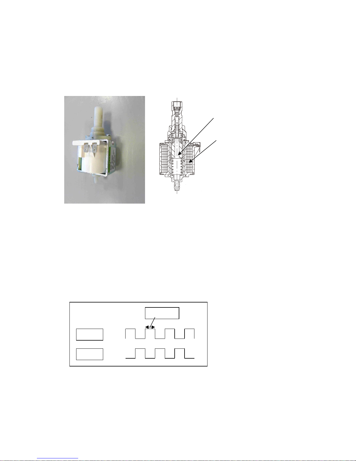
5.5 Water flow meter/water counter
The water flow meter measures the quantity of the water
flowing through the hot water pressure system.
Three functions are based on the water flow meter:
1. The water dosages for the consumptions are based on
quantity of the pulses generated by the flow meter.
2. During the start up procedure it is detected if water is flowing
into the system. If not, the machine will stop working and show
the error messages “start-up problem” and “no water
connected”
3. The amount of heating of the boiler is, besides the
measurement with the temperature probe, also based on the
quantity of incoming water.
The water flow meter is built in between the pressure reducer
and the pumps. It is a small turbine which produces electrical
pulses. Each 360º rotation produces 2 pulses in the sensor (Hall
element). The pulses are detected by the control system.
The tube to the water flow meter must be connected in the right position; the
flow meter cannot detect water in the reverse mode. There is a small arrow on
the water flow meter which shows the right direction.
The water flow meter is a 1.8 mm type.
Each pulse is about 0.8 ml of water.
Electrical connections/wire colors:
Number
Wire color
function
1
Red-white
Common (+)
2
Green-purple
Null (0)
3
Blue-black
Signal to the IO board
21
0
24V 0 24V
5.6 Pump
The pumps are generating the pressure and flow of the water.
The pumps increase the pressure to the required brewing pressure (1.5 till 10
bar).
The pump is a vibration pump. The plunger vibrates up and down, therewith a
pressure can be build-up.
The pump is a 24VAC pump, the electrical signal to the pump is a 24DC block
pulse.
The pressure can be adjusted by the electrical signal (pulse-width) to the pump.
A longer pulse gives a higher pressure because the plunger is lifted higher.
The maximum pulse width is 20. This figure can be set in the service program,
individual for every consumption.
Because of the high frequency of the pulses this electronic signal cannot be
measured with an ordinary volt meter.
The pulses for the two pumps runs out of phase so a stable high pressure is
offered to brew an espresso.
Pump 1
Pump 2
Pulswidth
plunger
coil
22
Electrical connections/wire colors:
Pump 1:
Number
Wire color
function
1
Grey-Blue
Common (+24V)
2
Yellow-Brown
Output (0)
Pump 2:
Number
Wire color
function
1
Black-Pink
Common (+24V)
2
Orange-White
Output (0)
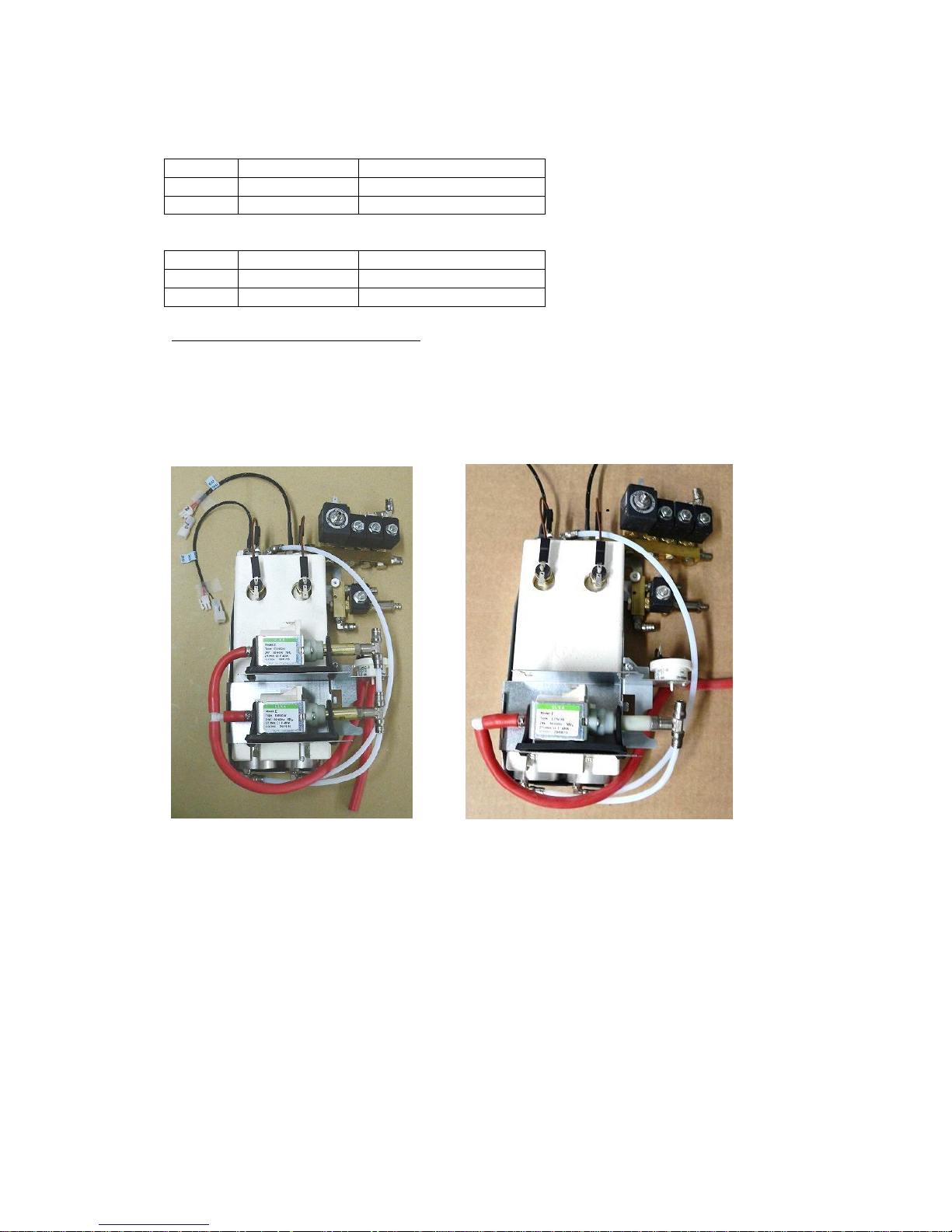
Machines with one or two pumps:
- The Fresh brew version without a bean hopper (Zia 6000) has just 1 pump and
is brewing coffee on a low 1-4 bar pressure.
- The B2C espresso machine has 2 pumps, parallel connected and can brew
espresso on 8-10 Bar or coffee on a low pressure 1-4 bar.
The variation in pressure generates an excellent coffee or espresso flavor.
Part number pump: 4EMT027
2 pumps system (Zia 8000 series)
1 pump system (Zia 6000 series)
23
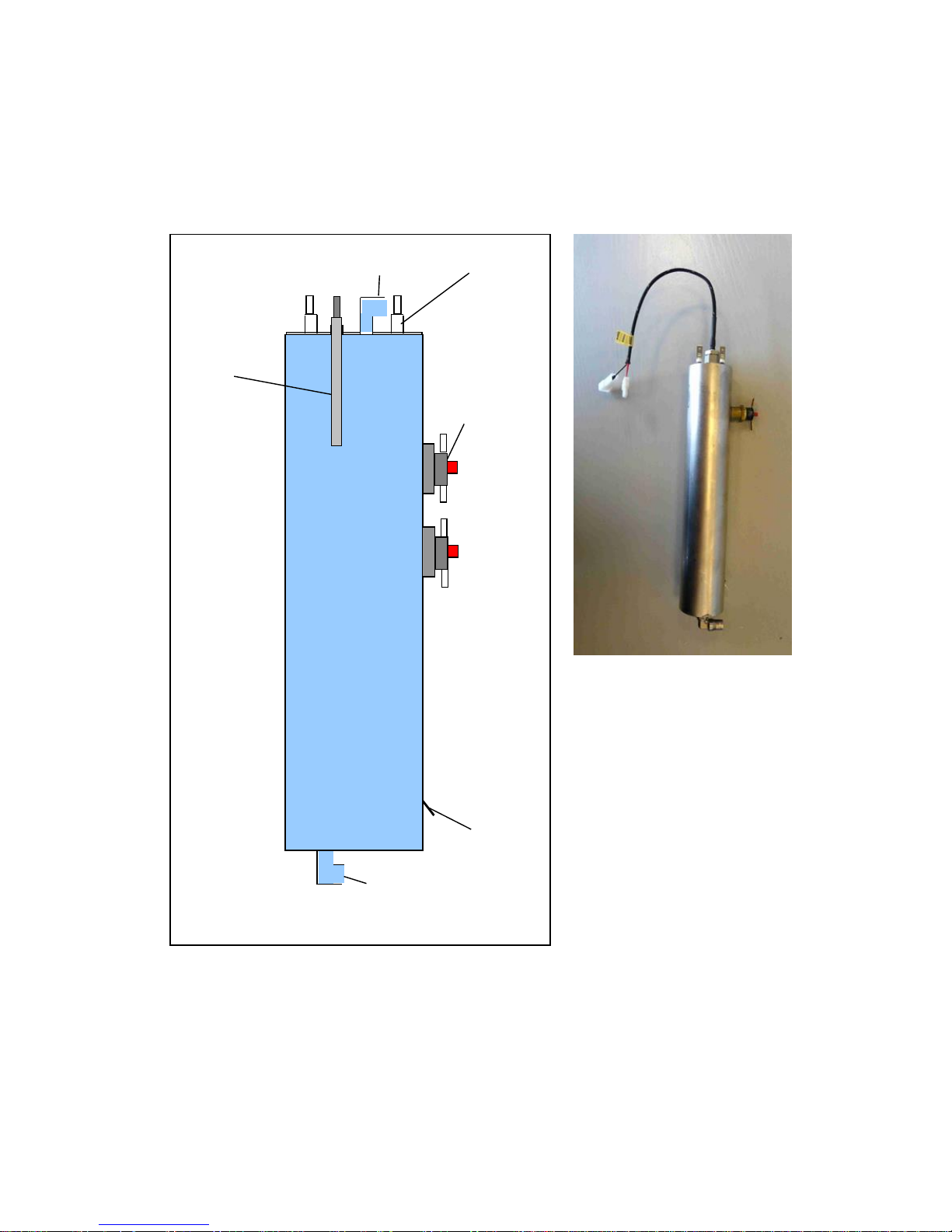
5.7 Boiler
The hot water is prepared in the boilers. The machine is equipped with two
boilers, made out of stainless steel.
The boilers are connected in serial; water from boiler 1 flows into boiler 2 and
from boiler 2 through outlet valves out of the hot water system.
The water inlet is in the bottom of the boiler, the outlet at the top.
Water inlet
Water outlet
Heater
Temperature
and level
sensor
Temperature
safety switch
(Clixon)
Ground
24
Electrical boiler connections:
Connections boiler 1
number
Wire color
function
1
Green-Purple
Temperature common
1
Pink
Temperature
2
Dark-red /Black
Level detection
3
Black
Heater phase
4
Blue
Heater neutral
5
Black
Temperature safety
6
Brown
Temperature safety
7
Yellow/grey
Earth boiler housing
Connections boiler 2
number
Wire color
function
1
Green-purple
Temperature common
1
White-pink
Temperature
2
Brown-black
Level detection
3
Black
Heater phase
4
Blue-white
Heater neutral
5
Black
Temperature safety
6
Brown-white
Temperature safety
7
Yellow/grey
Earth boiler housing
Heater:
The boiler has a 1,4 KW/240VAC heater or a 1,1KW/110VAC. The volume in the
boiler is 0,36 liter.
The boiler and heater are made of stainless steel. The heater is welded in the top
of the boiler.
The winding resistance of the heater is:
The heater is controlled by the control system. This is based on a combination of
detected temperature by the temperature sensor and the amount of incoming
water by the flow meter.
Heater
resistance
1400W 240VAC
39 - 40Ω
1100W 120VAC
12 – 13Ω
heater
Triac on
IOB
Temp.
safety
230VAC or
110VAC
1
3 4 6 7 2
5
Temp.
safety
25
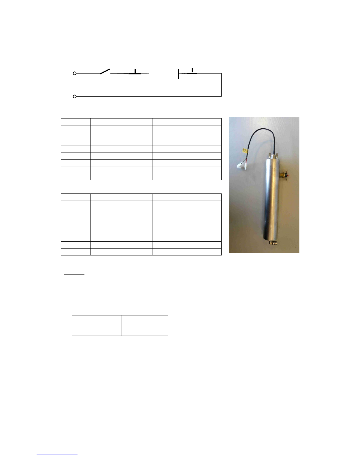
Temperature safety / clixon:
The temperature safety switch is positioned on the side of the boiler. In the
housing is a bi-metal disk which switch if the device gets too hot.
This safety protects the heater against overheating if the control system does not
switch off the heater.
The temperature safety (normally closed contact) switches off at a temperature of
110ºC +/- 5ºC. The safety switches the current to the heater directly off if the
boiler is overheating. The clixon is resettable after cooling down by pressing the
pin by hand.
Temperature/Level sensor:
The sensor in the boiler is a combined level and temperature probe. The sensor is
isolated from the boiler housing with a plastic isolation clamped with two nuts
around the stainless steel sensor housing.
If replacement is needed the sensor needs to be replaced complete, including
nuts.
Temperature:
The temperature is detected by a thermistor mounted in the stainless steel
housing. The control system is controlling the temperature in the boiler based on
the resistance of the thermistor.
Resistance of the thermistor:
Resistance
Temperature
6.5 k
95ºC
100 k
25ºC
126.7 k
20ºC
The temperature is adjustable in the settings of the control system.
The optimal temperature setting is 90ºC in boiler 1 and 92 ºC in
boiler 2. If no consumptions are made, the temperature in boiler 2
will automatically raise in about 25 minutes to 98º. Herewith the
first consumption with a cold brewer is brewed with incoming water
on a higher temperature, compensating the colder brewer.
The control system contains some safeties and warnings based on
the detected value of the temperature sensor.
A too high temperature, too low temperature, shortcut or
disconnected sensor is detected by the control system.
- Disconnected temp. sensor is generated if the resistance is above 350 k.
- Shortcut temp. sensor is generated if the resistance is below 1 k
Reset
26
Level:
The level in the boiler is detected by the stainless steel housing of the sensor. The
boiler is connected to ground. On the housing is a positive signal from the control
system. If the sensor is in the water, current is able to pass through the water.
The control system is detecting the water level because of this current.
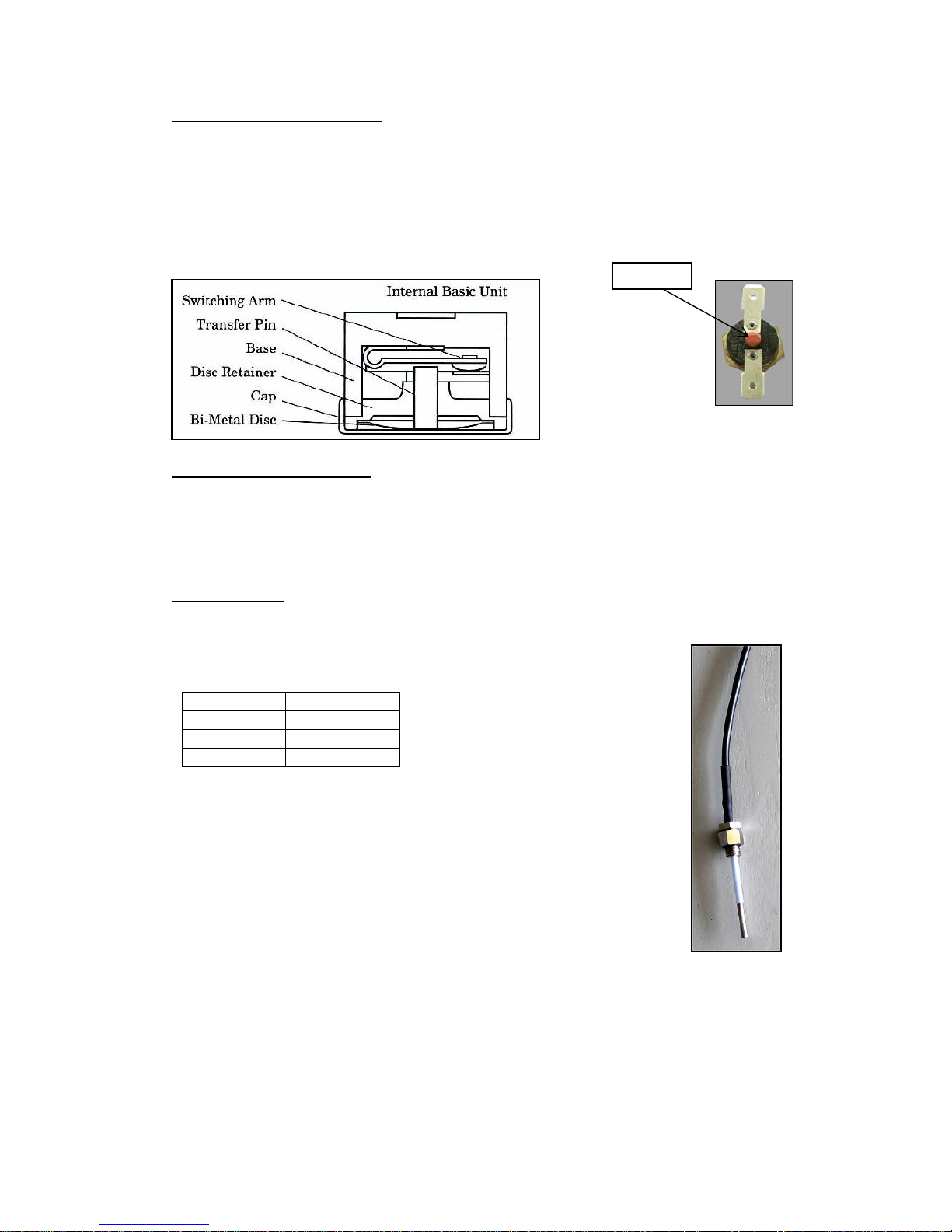
5.8 Position of valves in the hot water system
The manifold with valves is connected straight on the boiler with a bolt. This
connection is needed to keep the manifold with valves warm if the machine is not
used for a while.
Expansion valve
12-bar pressure
safety valve
2-bar pressure
valve
3-way coffee
valve
manifold
2-way hot water
outlet valve
2-way outlet
valve
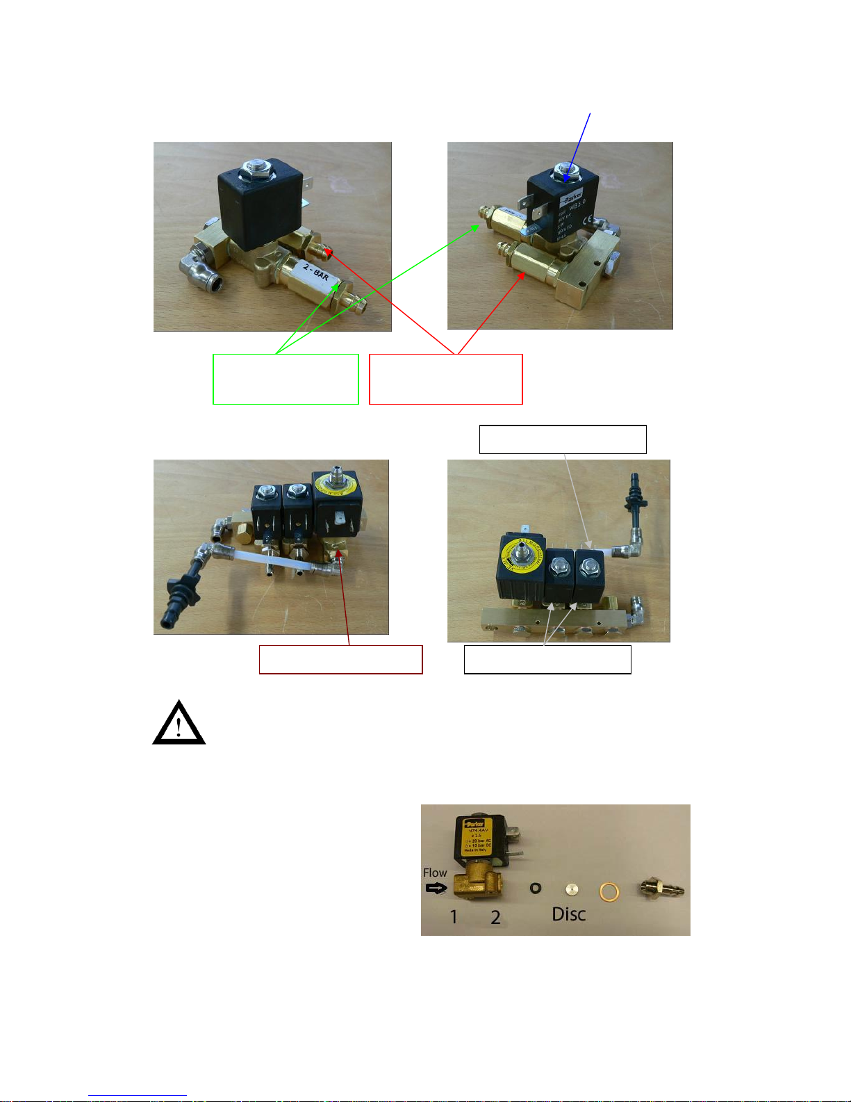
27
The two way hot water outlet valve is equipped with a special disc
between valve and hose nozzle.
This disc has a very small hole (0.7mm) in the middle. All the water
must flow through this very small hole, causing the air in the water to
dissolve.
If this disc is not fitted, tea made with hot water will have a foam layer
and will not look appealing.
Part numbers:
- 2 way valve: 4EMV031
- O-ring: 4ROR015
- disc: 5MVL176
- cupper ring: 4BPR039
- Hose nozzle G1/8": 4MPF044
Mounting sequence: as shown in picture.
2-bar pressure
valve
12-bar pressure
safety valve
3-way coffee valve
2-way outlet valve
Hot water valve
28
1
2
1
2
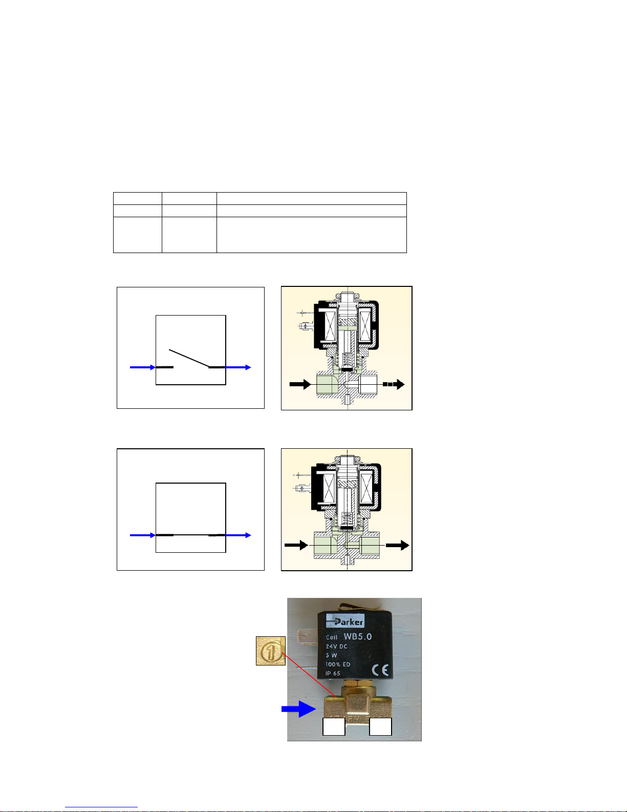
5.9 2-way valve / outlet valve
The two way valve is the outlet from the hot water system to a component.
The moveable plunger has an integral seat which, when the solenoid coil is
energized, moves off the valve (direct operated) orifice opening the valve.
When the coil is de-energized, a return spring repositions the plunger in the
original closing position on the valve, thus cutting off the flow of the fluid.
The valve is controlled by 24VDC from the IO-board.
Water connections:
Number
Function
Description
1
Input
Connected to manifold
2
Output
Connected to component
(Mixing system, hot water or 2-bar
valve)
Water flow in valve if coil de-energized: (no flow)
Water flow in valve if coil is energized:
The water connections on the valve are identified by numbers:
The water flow MUST BE from
number 1 to number 2!
1
2
 Loading...