

UDL5 – UHF mouse
Quick start manual
V27/09/07

UDL5 - UHF mouse · Quick start manual
© Copyright 2007 by deister electronic GmbH
All rights reserved. No part of this publication may be reproduced, stored in a retrieval
system, or transmitted, in any form or by any means, electronic, mechanical, photocopying,
recording, or otherwise, without prior written permission of deister electronic GmbH.
deister electronic GmbH reserves the right to make changes to any and all parts of this
documentation without obligation to notify any person or entity of such changes.
September 2007 SK
deister electronic GmbH
Hermann-Bahlsen Str. 11
30890 Barsinghausen
Germany
Phone: +49 (0) 51 05 - 51 61 11
Fax: +49 (0) 51 05 - 51 62 17
E-Mail: info@deister-gmbh.de
Web: www.deister.com
2
deister electronic GmbH 30890 Barsinghausen Germany V27/09/07

UDL5 - UHF mouse · Quick start manual
Content
1. UDL5 description.........................................................4
1.1 Components.......................................................................................................4
2. Mechanical Dimensions..............................................4
2.1 LEDs and Beeper.................................................................................................5
3. Configuration and setting...........................................5
3.1 Transmission protocol..........................................................................................5
4. Getting started............................................................6
4.1 Installing USB driver............................................................................................6
4.2 Installing RDemo...............................................................................................10
4.3 Get connection.................................................................................................10
4.4 Reading block data...........................................................................................14
4.5 Writing block data.............................................................................................15
4.6 EPC class1 gen2 tag functions............................................................................16
4.7 RDemo command builder..................................................................................16
5. EPC class1 gen2 memory organisation.....................17
V27/09/07 deister electronic GmbH 30890 Barsinghausen Germany
3
1. UDL5 description
1.1 Components
The UDL5 delivery contains:
• 1x UDL5 – UHF mouse
• 1x USB cable
• 1x CD with technical information and software
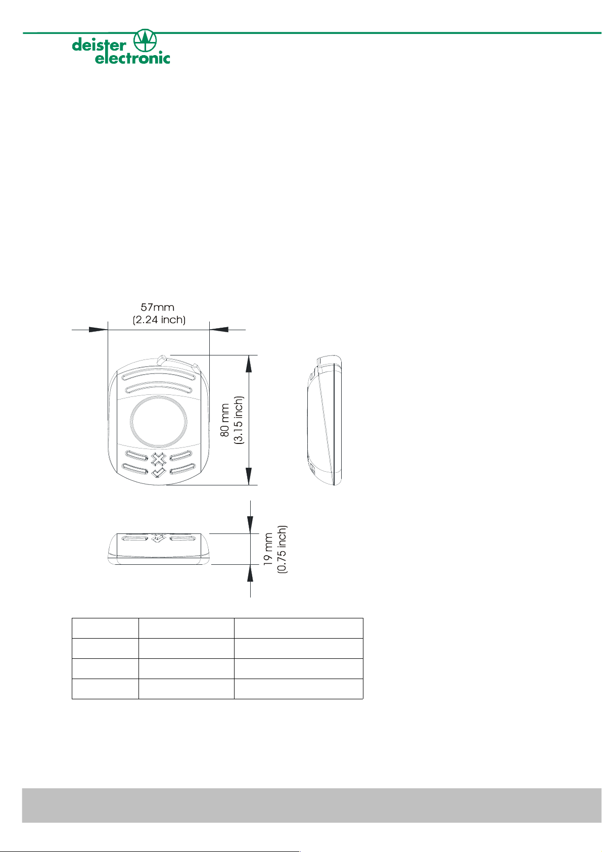
2. Mechanical Dimensions
All dimensions in mm (inch).
UDL5 - UHF mouse · Quick start manual
Symbol LED color Status
X red RF-field on/off
√ green reading/writing tags
blue power
Further explanation see next section 2.1 „LEDs and Beeper“.
4
deister electronic GmbH 30890 Barsinghausen Germany V27/09/07
UDL5 - UHF mouse · Quick start manual
2.1 LEDs and Beeper
The device is equipped with three LEDs and one beeper to indicate the reader status. The
following table refers to the standard settings (device set in trigger mode).
LEDs Status UDL5
blue and red: on
green: off
blue: on
red and green: off
blue and green: on
red: off
beeper: on
blue, green and red: on reader carries out a reset, RF-field is switched off,
reader is ready to operate, RF-field is switched off
reader is ready to operate, RF-field is switched on,
reader is ready to read or write to transponder
reader is ready to operate, communication between
reader and tag (reading/writing)
reader is not ready to operate
3. Configuration and setting
Please note: This manual is considered to be prelimiary.
In the standard configuration the device is set in “Trigger Mode“. This means the device waits
for a “Trigger On“ command to switch the RF-field on and a „Trigger Off“ command to switch
the RF-field off. These software commands can be sent to the device using RDemo software (to
be found on the CD which is part of the UDL5 package).
The UDL5 in its current version is EPC class1 gen2 complicant only.
3.1 Transmission protocol
The communication of the UDL5 is based on the “deBus” protocol. For integration into userdefined applications please contact your local sales and service center (see end of document).
V27/09/07 deister electronic GmbH 30890 Barsinghausen Germany
5
UDL5 - UHF mouse · Quick start manual
4. Getting started
4.1 Installing USB driver
First the USB driver has to be installed. The following steps show how to install the driver
under Windows XP (Windows Vista is supported as well):
• Connect the UDL5 via USB cable to a spare USB Port at your Host/PC
(USB cable as part of delivery of UDL5).
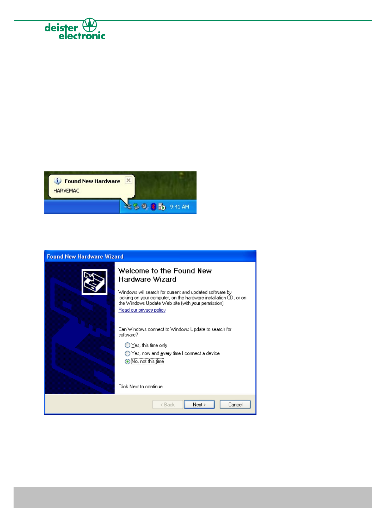
• Windows XP indicates the new hardware with the message
“Found New Hardware: HARVEMAC“.
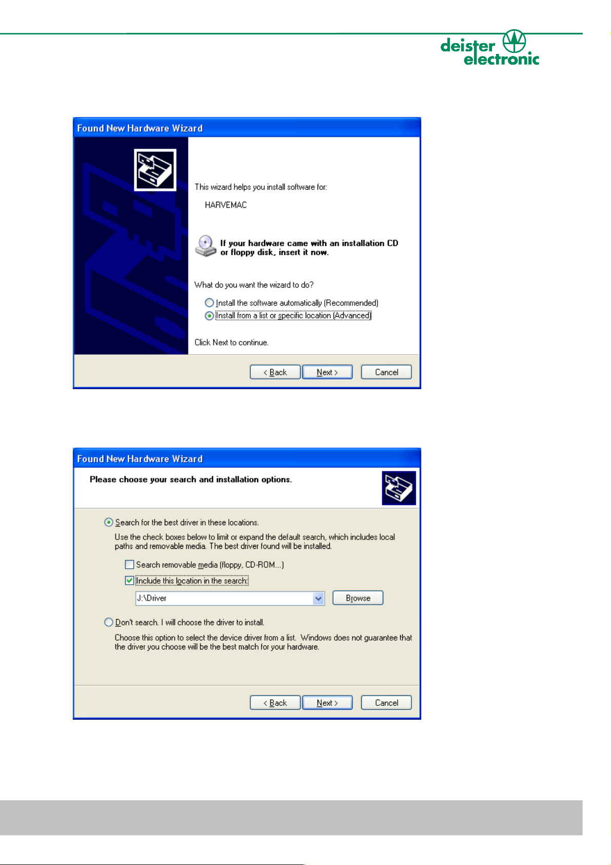
• The “Found New Hardware Wizard“ will now be started automatically.
Select “No, not this time“ and click “Next“.
If this procedure failed, the search for new hardware can be started manually by click on:
“Start“ -> “Settings“ -> “Control Panel“ -> “System“ -> “Hardware“ -> “Device
Manager“. Select the USB device, marked by a yellow question mark.
6
deister electronic GmbH 30890 Barsinghausen Germany V27/09/07
UDL5 - UHF mouse · Quick start manual
• Select “Install from a list or specific location (Advanced)“ and click “Next“.
• Select “Search for the best driver in these locations“. Enter path name into the combo-
box or browse to path using the “Browse“ button.
V27/09/07 deister electronic GmbH 30890 Barsinghausen Germany
7
UDL5 - UHF mouse · Quick start manual
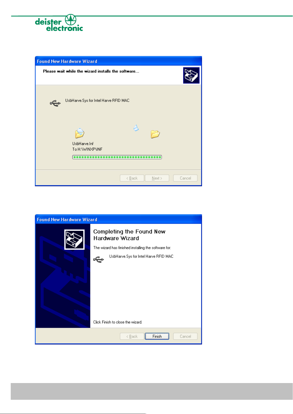
• The screen below will be shown while Windows XP copies the required files.
• The following message indicates a successful installation process. Click “Finish“ to
close the wizard. Now the UDL5 is successfully installed.
8
deister electronic GmbH 30890 Barsinghausen Germany V27/09/07

UDL5 - UHF mouse · Quick start manual
• After successful installation of the USB driver, the UDL5 is ready for use. The “Device
Manager“ indicates the UDL5 as an additional device named “UsbHarve.Sys for Intel
Harve RFID MAC“.
V27/09/07 deister electronic GmbH 30890 Barsinghausen Germany
9

UDL5 - UHF mouse · Quick start manual
4.2 Installing RDemo
The RDemo program can be found on the CD as part of the UDL5 package. For installation
proceed as follows:
• Start installing RDemo with double click on file or icon:
4.3 Get connection
• After successfull installation of RDemo start the program with double click
on file or icon:
• Select “Port“ -> “USB“.
10
deister electronic GmbH 30890 Barsinghausen Germany V27/09/07

UDL5 - UHF mouse · Quick start manual
• Click on button “deBus“.
• Select “baud rate: all“ and click “Detect Device(s)“.
• RDemo starts scanning for connected deBus devices.
V27/09/07 deister electronic GmbH 30890 Barsinghausen Germany
11
UDL5 - UHF mouse · Quick start manual
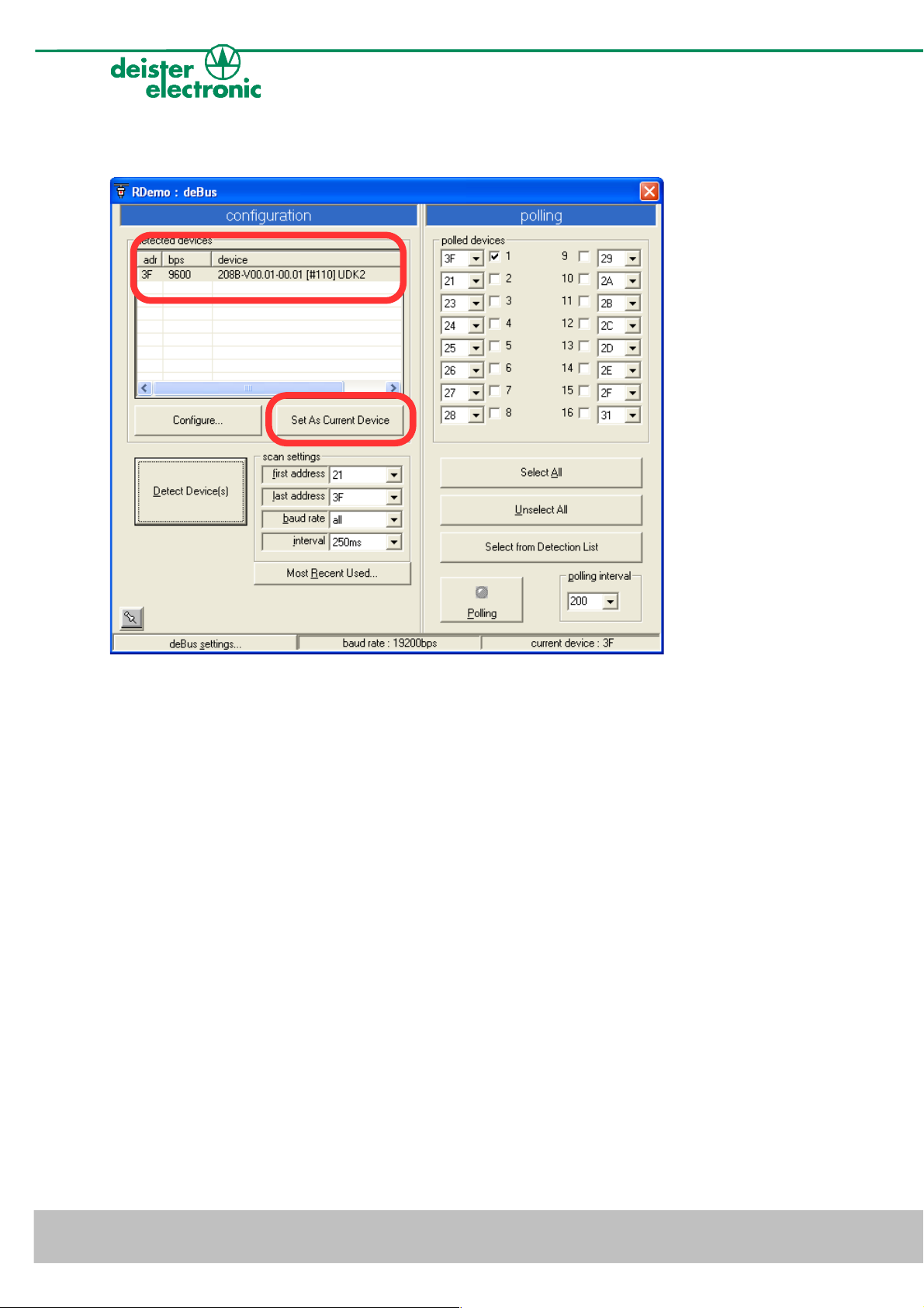
• After successful search the UDL5 will be shown as a detected device.
• Select the UDL5 with click on the left mouse button, then click “Set As Current Device“
and close the window.
12
deister electronic GmbH 30890 Barsinghausen Germany V27/09/07

UDL5 - UHF mouse · Quick start manual
• Click on the “Version“ button. A “version received“ message in the bottom state bar
indicates a successful version request of the UDL5.
• Click on the “Trigger On“ button in order to switch on the RF-field. Present an EPC
class1 gen2 tag in front of the reader and RDemo will display the tag read.
• Click on the „Trigger Off“ button in order to switch off the RF-field.
V27/09/07 deister electronic GmbH 30890 Barsinghausen Germany
13

UDL5 - UHF mouse · Quick start manual
4.4 Reading block data
The reading function “Transponder“ -> “Read“ can be used to read block data of an EPC
class1 gen2 transponder. To do so proceed as follows:
• Choose the tag type (please note: The current UDL5 version supports EPC class1 gen2
tags only), the serial number (EPC) of the tag to be read and one of the predefined
memory blocks.
• Click on the “Read!“ button and present the EPC class1 gen2 tag within the RF-field.
The block data will be shown in the „Transponder data“ window (see below).
For more details concerning EPC class1 gen2 tag memory organisation see section
5. “EPC class1 gen2 memory organisation“.
14
deister electronic GmbH 30890 Barsinghausen Germany V27/09/07

UDL5 - UHF mouse · Quick start manual
4.5 Writing block data
The writing function “Transponder“ -> “Write“ can be used to write block data to an EPC
class1 gen2 transponder. To do so proceed as follows:
• Choose a tag type (please note: The current UDL5 version supports EPC class1 gen2
tags only), the serial number (EPC) of the tag, a predefined memory section and the
data to be written.
• Click on the “Write!“ button and present the EPC class1 gen2 tag within the RF-field.
The block data will be shown in the “Monitor“ window. RDemo indicates successful
writing with a “write successful“ message (in the “Monitor“ bottom state bar, see
below).
For more details concerning EPC class1 gen2 tag memory organisation see section
5. “EPC class1 gen2 memory organisation“.
V27/09/07 deister electronic GmbH 30890 Barsinghausen Germany
15

UDL5 - UHF mouse · Quick start manual
4.6 EPC class1 gen2 tag functions
Additional tag functions like “Kill command“ and all others are not supported by the
current version of UDL5. Please consult the next sales and service center for details.
4.7 RDemo command builder
For sending a user-defined deBus command to the UDL5, the “Command Builder“ is a
useful tool.
• Go to “Special Functions“ and select “Command Builder“.
• Enter a user-defined deBus command string without dummy bytes, CRC and STOP
bytes and then click “send command“.
16
deister electronic GmbH 30890 Barsinghausen Germany V27/09/07

UDL5 - UHF mouse · Quick start manual
3 USER
[15:0]
… …
…
[N:N-15] [0:15] 192
2 TID
… … …
TID [15:0] [16:31] 129
TID [31:16] [0:15] 128
1 EPC
EPC [15:0]
… …
…
EPC [N:N-15] [32:47] 66
PC [15:0] [16:31] 65
CRC-16 [15:0] [0:15] 64
0 RESERVED
… … …
Access Password [15:0] [48:63] 3
Access Password [31:16] [32:47] 2
Kill Password [15:0] [16:31] 1
Kill Password [31:16] [0:15] 0
Bank No.
(decimal form)
Bank
Name
Block Memory Content
[MSB:LSB]
(decimal form)
Memory Bank
Addresses
[MSB:LSB] (decimal
form)
Block Address
(decimal form)
5. EPC class1 gen2 memory organisation
This paragraph refers to the document “EPCglobal™, Specification for RFID Air Interface”,
Version 1.0.9.
The tag memory is divided into four memory banks. Each memory bank consists of several
blocks, each block has the size of 2 bytes. The banks RESERVED, EPC and TID must always
be available, the USER bank is optional.
• RESERVED: Non-Volatile-Memory, this memory contains a 32 bit Kill Password and a
32 bit Access Password.
• EPC (Electronic Product Code): This bank contains the CRC-16 (cyclic redundancy
check), PC (Protocol Control) and EPC. The PC bits contain information about the tag,
e.g. length of the EPC. The EPC begins at block address 66 (dec), MSB first. In case of
a 96 bit EPC it has the size of 6 blocks.
• TID (Transponder Identification): The TID memory contains data about the
manufacturer. Tags may contain specific data within the TID memory, beginning at
block address 130 (dec), e.g. a tag serial number.
• USER: allows user specific data storage. The memory organisation is user-defined.
V27/09/07 deister electronic GmbH 30890 Barsinghausen Germany
17

UDL5 - UHF mouse · Quick start manual
6. Regulatory notices
6.1 Europe
Hereby, deister electronic GmbH declares, that this equipment - if used according to the
instructions - is in compliance with the essential requirements and other relevant provisions
of the RTTE Directive 1999/5/EC.
A full declaration of conformity can be requested at:
info@deister-gmbh.de
Approved for use in all European countries.
6.2 FCC Digital Device Limitations
Radio and Television Interference
This equipment has been tested and found to comply with the limits for a digital device,
pursuant to Part 15 of the FCC rules. These limits are designed to provide reasonable
protection against harmful interference when the equipment is operated in a commercial
environment. This equipment generates, uses and can radiate radio frequency energy and,
if not installed and used in accordance with the instruction manual, may cause harmful
interference to radio communications. Operation of this equipment in a residential area is
likely to cause harmful interference, in which case the user will be required to correct the
interference at his own expense.
This device complies with Part 15 of the FCC rules. Operation is subject to the following
two conditions: (1) This device may not cause harmful interference, and (2) this device
must accept any interference received, including interference that may cause undesired
operation.
In order to maintain compliance with FCC regulations, shielded cables must be used with
this equipment. Operation with non-approved equipment or unshielded cables is likely to
result in interference to radio and television reception.
Caution! Changes or modifications not expressly approved by the manufacturer could void
the user´s authority to operate this equipment.
18
deister electronic GmbH 30890 Barsinghausen Germany V27/09/07

UDL5 - UHF mouse · Quick start manual
Notes:
V27/09/07 deister electronic GmbH 30890 Barsinghausen Germany
19

Notes:
UDL5 - UHF mouse · Quick start manual
20
deister electronic GmbH 30890 Barsinghausen Germany V27/09/07

UDL5 - UHF mouse · Quick start manual
Notes:
V27/09/07 deister electronic GmbH 30890 Barsinghausen Germany
21

Germany:
deister electronic GmbH
Hermann-Bahlsen Str. 11
30890 Barsinghausen
Tel.: +49 (0) 51 05 - 51 61 11
Fax: +49 (0) 51 05 - 51 62 17
info@deister-gmbh.de
www.deister.com
deister worldwide
Belgium & Luxembourg:
deister electronic office
Business Park E 19
Battelsesteenweg 455/A
2800 Mechelen
Tel.: +32 (0) 15 - 28 09 68
Fax: +32 (0) 15 - 28 09 71
info@benelux.deister.com
France:
deister electronic france
101 rue Pierre Semard
92320 Chatillon
Tel.: +33 (0) 1 47 - 35 78 78
Fax: +33 (0) 1 47 - 35 92 59
info@deister.fr
Great Britain:
deister electronic (UK) Ltd.
Stapleton Way, Enterprise Park
Spalding, Lincolnshire
PE11 3YQ
Tel.: +44 (0) 1775 - 717100
Fax: +44 (0) 1775 - 717101
info@deister.co.uk
The Netherlands:
deister electronic office
Tolnasingel 3
2411 PV Bodegraven
Tel.: +31 (0) 1726 - 32970
Fax: +31 (0) 1726 - 32971
info@nl.deister.com
Canada:
deister electronic Inc.
1099 Kingston Road, Suite
212
Pickering, ON L1V 1B5
Tel.: +1 905 - 837 5666
Fax: +1 905 - 837 0777
info@deister-electronic.com
Japan:
deister electronic Japan, LTD.
Toshiba Hoshikawa Bldg. 4F
2-4 Kawabe-chô
Hodogaya-ku, Yokohama-shi
Kanagawa, 240-0001
Tel.: +81 (0) 45 340 1831
Fax: +81 (0) 45 340 1801
info@deister.jp
USA:
deister electronic USA Inc.
9303 Grant Avenue
Manassas, VA 20110
Tel.: +1 703 - 368 2739
Fax: +1 703 - 368 9791
info@deister.com
 Loading...