


UDL120
Installation & Operating
Instructions
V08/07/09
#896068

UDL120
© Copyright 2009 by deister electronic GmbH
All rights reserved. No part of this publication may be reproduced, stored in a retrieval
system, or transmitted, in any form or by any means, electronic, mechanical, photocopying,
recording, or otherwise, without prior written permission of deister electronic GmbH.
deister electronic GmbH reserves the right to make changes to any and all parts of this
documentation without obligation to notify any person or entity of such changes.
Juli 2009 IO/PF/BF
deister electronic GmbH
Hermann-Bahlsen Str. 11
30890 Barsinghausen
Germany
Phone: +49 (0) 51 05 - 51 61 11
Fax: +49 (0) 51 05 - 51 62 17
E-Mail: info.de@deister.com
Web: www.deister.com
2 lo_udl120_io_en V08/07/09

UDL120
Contents
1. General.......................................................................4
2. Technical Data............................................................5
3. Mechanical Dimensions..............................................6
3.1 Dimensions UDL120 with steel sides......................................................................6
3.2 Dimensions UDL120 without steel sides.................................................................7
3.3 Picture UDL120...................................................................................................8
4. Wiring.........................................................................9
4.1 RS485................................................................................................................9
5. Mounting on Forklift.................................................10
5.1 Mounting of UDL120 with steel sides (Protection Set 1)..........................................10
5.1.1 Mounting steel sides.................................................................................10
5.1.2 Drilling Pattern for mounting steel sides.......................................................11
5.2 Mounting of UDL120 without steel sides..............................................................12
5.2.1 Drilling Pattern for direct mounting of UDL120............................................13
5.3 Mounting UDL120 onto steel sides......................................................................14
6. Function of LEDs........................................................15
7. Communication.........................................................15
7.1 Communication via deBus protocol (standard)......................................................15
7.2 Communication via Bluetooth™ (optional)...........................................................15
7.2.1 Connecting to Bluetooth™ module (pairing)................................................15
7.2.2 Configuration mode of Bluetooth™ module.................................................16
7.2.3 Transmitting power...................................................................................16
8. Accessories................................................................17
8.1 Basic principle of forklift application....................................................................17
9. Regulatory Notices....................................................18
V08/07/09 lo_udl120_io_en 3

UDL120
1. General
The UDL120 contains an integrated RFID antenna for contactless reading of transponders
fixed on storage racks. It has been designed for fast and faultless electronic recognition of
goods in transit (i.e. palettes) and is increasingly used within electronic inventory control
systems.
The reader can be mounted directly onto the fork carrier between the forks of a forklift.
Due to its flat mounting height (installation depth only 40 mm) any contact to the
transported goods will be avoided. Solid metal side cheeks (optionally available) prevent
the reader from being damaged by the transported goods and mounting on buffers
provides reasonable absorption of shocks and vibrations.
An ultrasonic sensor in the middle of the housing (optional) detects loading of the forks
and reports it to the control unit (terminal) of the forklift. This will initiate a reading process,
in which the transponder fixed to the storage rack is being read.
The reading result contains the defined storage position of the rack using the specific
transponder ident number and is instantly being reported to the terminal.
The communication between antenna and terminal can either be carried out via cable
using RS485 or wireless via Bluetooth™.
For power supply the reader requires a power connection directly at the fork carrier of the
lift mast (12...24 V/DC).
As this document is solely intended for application of the UDL120 on forklifts, the metal steel sides
(Protection Set 1) are included into all image presentations for reasons of clarity.
4 lo_udl120_io_en V08/07/09

UDL120
2. Technical Data
Dimensions (mm): 172 x 148 x 40
Weight: approx. 730 g (without steel sides)
approx. 1500 g (with steel sides)
Material: PA6, black (front of housing)
PMMA (back of housing)
steel (sides; PS1 optional)
Protection Class: IP 65
Operating Temperature: -25 °C...+50 °C
Storage Temperature: -40 °C...+85 °C
Voltage Supply: 12...24 V/DC via M8 (4-pole)
Power Consumption: 7 W (operating status) / 2.5 W (standby)
Transmission Frequency: 865-868 MHz (EU)
902-928 MHz (US)
Antenna:
Beam Width: 90°
Polarization: circular (LHCP)
Reading/Writing Distance: up to 1.5 m, depending on type of transponder
and environmental conditions
Radiated Transmit Power: max. 200 mW E.R.P. (ETSI EN 302 208),
330 mW E.I.R.P. (FCC Part.15), optional
Transponder Protocols: ISO 18000-6 C
EPC Class 1 Gen 2
Interfaces: RS485
Bluetooth™ Class 1 (optional)
Anticollision: simultaneous reading of several transponders
Reading Mode: Dense Reader Mode can be activated
Ultrasonic Sensor: range up to 70 cm distance
Signalling (optical): LEDs (yellow, green, red)
Conformity:
(Exposition of persons EN 50364
against EM fields)
EMV EN 301 489
Air interface (EU) EN 302 208 (DRM)
V08/07/09 lo_udl120_io_en 5
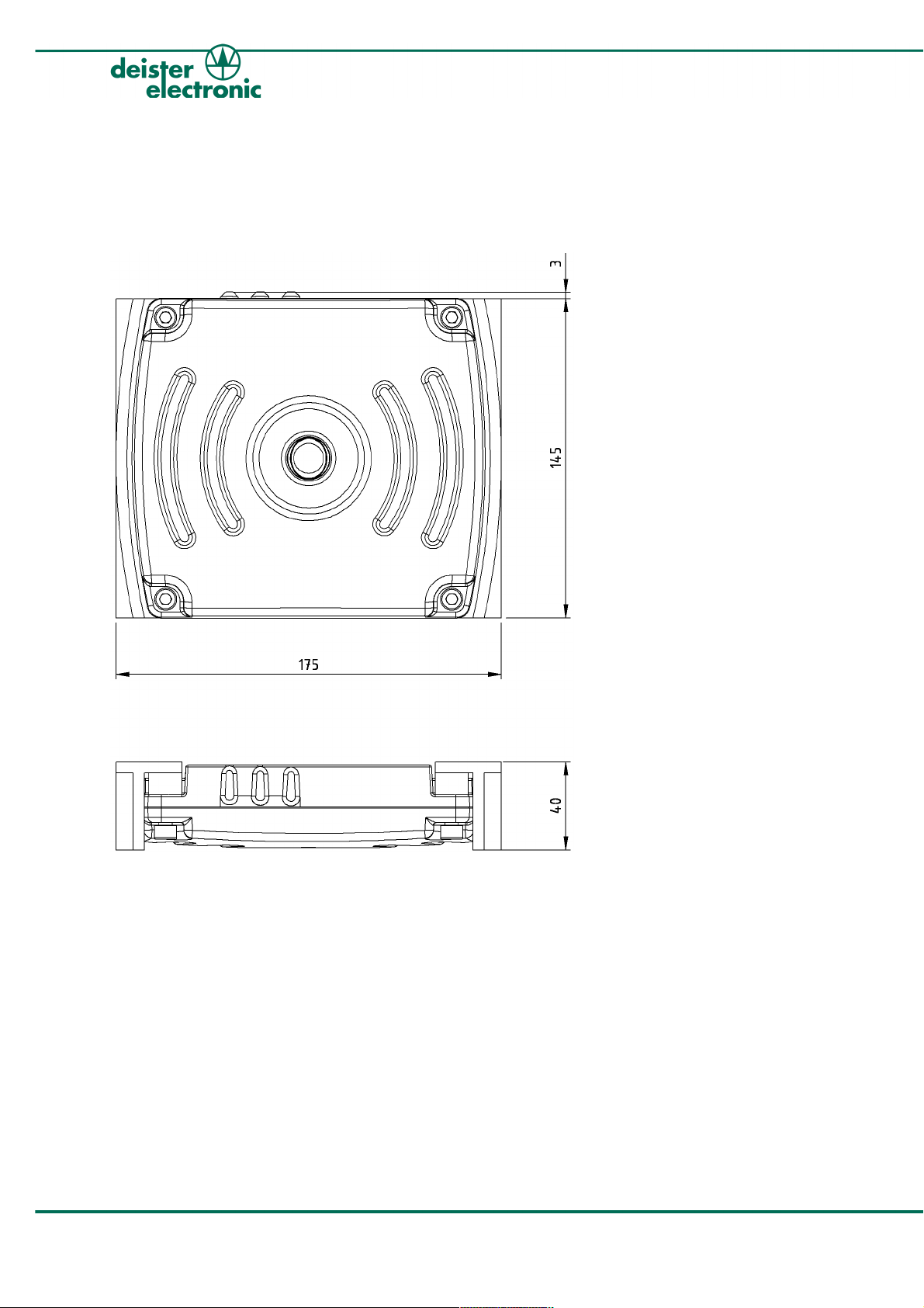
3. Mechanical Dimensions
(All dimensions in mm.)
3.1 Dimensions UDL120 with steel sides
UDL120
Figure 3.1.1: Mechanical Dimensions of UDL120 with steel sides
6 lo_udl120_io_en V08/07/09

UDL120
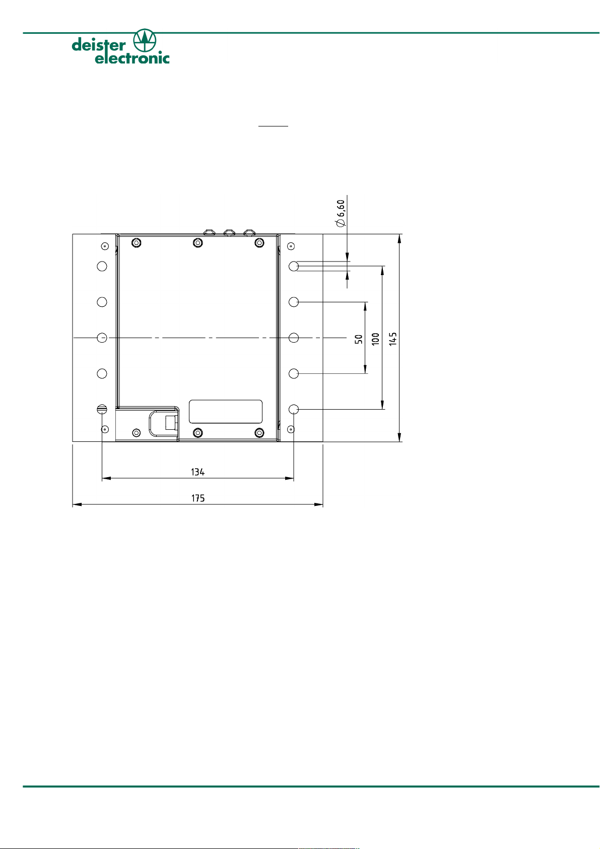
3.2 Dimensions UDL120 without steel sides
Figure 3.2.1: Mechanical Dimensions of UDL120 without steel sides
V08/07/09 lo_udl120_io_en 7

3.3 Picture UDL120
LED
LED
LED
red
green
yellow
UDL120
Ultrasonic sensor
Figure 3.3.1: Picture of UDL120 with LEDs and ultrasonic sensor
8 lo_udl120_io_en V08/07/09

UDL120
4. Wiring
4.1 RS485
The pin assignment for the voltage supply and data transfer via RS485 is as follows:
Figure 4.1.1: Pin assignment M8 connector (RS485)
pin assignment (M8): PIN 1: VCC (brown)
PIN 2: RS485 A (white) -->(optional*)
PIN 3: GND (blue)
PIN 4: RS485 B (black) -->(optional*)
* In case of communication solely via Bluetooth™ PIN 2 and 4 do not have to be assigned.
V08/07/09 lo_udl120_io_en 9
UDL120
5. Mounting on Forklift
5.1 Mounting of UDL120 with steel sides (Protection Set 1)
5.1.1 Mounting steel sides
The mounting of the two steel sides has to be carried out by the customer between the forks of the
fork carrier with 3 countersunk head screws (M6) on each side (drilling distances see per drawing):
Figure 5.1.1: Mounting UDL120 with steel sides (Protection Set 1)
10 lo_udl120_io_en V08/07/09

UDL120
5.1.2 Drilling Pattern for mounting steel sides
For the drilling pattern scale 1:1 see extra instruction leaflet inside the package.
Figure 5.1.2: Drilling Pattern for mounting steel sides to UDL120
V08/07/09 lo_udl120_io_en 11

5.2 Mounting of UDL120 without steel sides
UDL120
Figure 5.2.1: Mounting UDL120 without steel sides
12 lo_udl120_io_en V08/07/09

UDL120
5.2.1 Drilling Pattern for direct mounting of UDL120
For the drilling pattern scale 1:1 see extra instruction leaflet inside the package.
Figure 5.2.2: Drilling Pattern for direct mounting of UDL120
V08/07/09 lo_udl120_io_en 13
UDL120
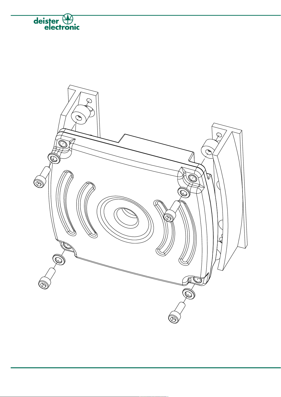
5.3 Mounting UDL120 onto steel sides
Mounting of the reader onto the metal bracket has to be carried out using the 4 supplied
screws (DIN 912 cylinder head bolt, allen head screw) and the according washers.
For additional absorption of shocks and vibrations the reader has to be mounted onto the
steel sides using the four supplied buffers (see picture below):
Figure 5.3.1: Mounting UDL120 onto steel sides
14 lo_udl120_io_en V08/07/09

UDL120
6. Function of LEDs
The function of the three LEDs on top of the reader (see also 3.1 Picture) is as follows:
yellow LED is blinking: standard operating status in trigger mode;
device is ready to read;
RF field is switched off
yellow LED is permanently on: standard operating status; device is ready to read;
RF field is switched on
green LED shortly flashes: shows successful reading of a transponder
red LED is active: shows a general malfunction within the system
7. Communication
7.1 Communication via deBus protocol (standard)
The standard way of communication between UDL120 and Terminal (via CB2, CB1, SNG
etc.) is carried out using the deBus protocol on the RS485 bus.
7.2 Communication via Bluetooth™ (optional)
Contactless communication is carried out via Bluetooth™ with an Ezurio BISM2 module.
This module provides a virtual serial interface for communication with the reader using
the Bluetooth™ SPP (Serial Port Profile). The serial interface of the PC has to be
configured as follows:
Data rate: 115200 Baud
Data bits: 8
Stop bits: 1
Parity: none
7.2.1 Connecting to Bluetooth™ module (pairing)
A Bluetooth™ stick for the PC is needed, which contains SPP (Serial Port Profile). The
according Bluetooth™ module can be found by scanning all available Bluetooth™ devices.
The reader reports with „UDL120 #xxx“. The required PIN for the Bluetooth™ connection
is „0000“ (default setting). As long as the memory capacity of the Bluetooth™ module is
sufficient, the module stores the identification of the communication partner so that the
pairing process does not have to be repeated.
V08/07/09 lo_udl120_io_en 15

UDL120
7.2.2 Configuration mode of Bluetooth™ module
Configuration of the Bluetooth™ module takes place via Bluetooth™ interface. The
following parameters can be adjusted:
transmitting power of the Bluetooth™ module
The Bluetooth™ module needs to be switched into the configuration mode first in order to
change any of its settings. In order to do so, three consecutive quotation marks („!!!“) need to
be sent with a time difference of 100 ms between each other using the Bluetooth™ interface.
This can be done for example by help of the Windows program Hyperterminal, which can
access the Bluetooth™ module on the PC using the virtual serial interface.
In order to leave the configuration mode the following command
ATO<Enter>
needs to be sent to the module. After any configuration process a Reset is required.
7.2.3 Transmitting power
The Bluetooth™ module can be configured for a transmitting power between -27 dBm and
+6 dBm. The current transmitting power can be requested by using the following command
ATS541<Enter>
Configuration of the transmitting power is carried out using the command
ATS541?=m<Enter>
The parameter m can be configured with a value between -27 und +6. Changed settings
become active immediately but are only stored within the volatile memory. In case the
module can not be accessed any longer due to an incorrectly adjusted transmitting power,
the original value can be restored by switching the reader on and off.
If all changes of the settings are correct, the configuration has to be transferred into the
non-volatile memory by using the following command
AT&W<Enter>
16 lo_udl120_io_en V08/07/09

UDL120
8. Accessories
Further accessories such as necessary connection cables or peripheral devices (Connection
Box CB1, Connection Box CB2) are shortly explained in the following table and the chart
below will additionally illustrate the basic concept. For all peripheral devices mentioned below
there are separate Wiring and Installation Instructions available which can be obtained on
request from your local sales and service partner or directly at deister electronic GmbH.
CC1 Connection cable
M8 female connector 90° 4-pin with 3 m cable
Art.No. 09287.000
PS1 Protection Set 1
Art.No. 09286.000
CB1 Connection Box 1
Art.No. 09284.000
Steel sides for mounting the reader onto the fork
carriage; weight approx. 767 g
Interface converter;
converts data from Host/PC on the USB bus into
RS485 signals; serves as voltage supply for the
entire RFID system by being connected to a DC/DC
converter (see below)
CB2 Connection Box 2
(for up to 5 reader)
Art.No. 09285.000
Acts as RS485 hub;
serves as data transmitter from the Host/PC (via
CB1) and as voltage supply (from the CB1) for all
separately connected readers (see below)
Table 1: Accessories for UDL120
8.1 Basic principle of forklift application
RS485
UDL120
Terminal
(3rd Party)
USB
CB1
RS485RS485
CC1
CB2
UDLxxx
UDLxxx
UDLxxx
DC/DC converter
(3rd Party)
Figure 8.1.1: Basic principle of forklift application
24 V/DC
UDLxxx
V08/07/09 lo_udl120_io_en 17

UDL120
9. Regulatory Notices
Hereby, deister electronic GmbH declares that this equipment - if used according to the
instructions - is in compliance with the essential requirements and other relevant provisions
of the RTTE Directive 1999/5/EC.
A full declaration of conformity can be requested at:
info@deister-gmbh.de
Approved for use in all European countries.
FCC Digital Device Limitations
Radio and Television Interference
This equipment has been tested and found to comply with the limits for a Class A digital
device, pursuant to Part 15 of the FCC rules. These limits are designed to provide
reasonable protection against harmful interference when the equipment is operated in a
commercial environment. This equipment generates, uses and can radiate radio frequency
energy and, if not installed and used in accordance with the instruction manual, may
cause harmful interference to radio communications. Operation of this equipment in a
residential area is likely to cause harmful interference, in which case the user will be
required to correct the interference at his own expense.
This device complies with Part 15 of the FCC rules. Operation is subject to the following
two conditions: (1) This device may not cause harmful interference, and (2) this device
must accept any interference received, including interference that may cause undesired
operation.
In order to maintain compliance with FCC regulations, shielded cables must be used with
this equipment. Operation with non-approved equipment or unshielded cables is likely to
result in interference to radio and television reception.
Caution! Changes or modifications not expressly approved by the manufacturer could void
the user´s authority to operate this equipment.
18 lo_udl120_io_en V08/07/09

UDL120
FCC Notice
To comply with FCC Part 15 rules in the United States, the system must be professionally
installed to ensure compliance with the Part 15 certification. It is the responsibility of the
operator and professional installer to ensure that only certified systems are deployed in the
United States. The use of the system in any other combination (such as co-located
antennas transmitting the same information) is expressly forbidden.
FCC Radiation Exposure Statement
This equipment complies with the FCC radiation exposure limits set forth for an
uncontrolled environment. This equipment should be installed and operated with minimum
distance of 20 cm between the radiator and the human body.
Industry Canada
This Class A digital apparatus complies with Canadian ICES-003.
Cet appareil numérique de la classe A est conforme à la norme NMB-003 du Canada.
V08/07/09 lo_udl120_io_en 19

Germany
deister electronic GmbH
Hermann-Bahlsen Str. 11
30890 Barsinghausen
Tel.: +49 (0) 51 05 - 51 61 11
Fax: +49 (0) 51 05 - 51 62 17
info.de@deister.com
www.deister.com
deister worldwide
Benelux:
deister electronic office
Business Park E 19
Battelsesteenweg 455/A
2800 Mechelen
Tel.: +32 (0) 15 - 28 09 68
Fax: +32 (0) 15 - 28 09 71
info.be@deister.com
France:
deister electronic france
101 rue Pierre Semard
92320 Chatillon
Tel.: +33 (0) 1 47 - 35 78 78
Fax: +33 (0) 1 47 - 35 92 59
info.fr@deister.com
Great Britain:
deister electronic (UK) Ltd.
Stapleton Way, Enterprise Park
Spalding, Lincolnshire
PE11 3YQ
Tel.: +44 (0) 1775 - 717100
Fax: +44 (0) 1775 - 717101
info.uk@deister.com
Japan:
deister electronic Japan, LTD.
Toshiba Hoshikawa Bldg. 4F
2-4 Kawabe-chô
Hodogaya-ku, Yokohama-shi
Kanagawa, 240-0001
Tel.: +81 (0) 45 340 1831
Fax: +81 (0) 45 340 1801
info.jp@deister.com
USA:
Deister Electronics USA, Inc.
9303 Grant Avenue
Manassas, VA 20110
Tel.: +1 703 - 368 2739
Fax: +1 703 - 368 9791
info.us@deister.com
 Loading...