


Deister Electronic MODEL245 Users Manual


GE Contactless
Smart Card Reader
Model 240 and 245
Installation Guide
791 Park of Commerce Boulevard
Suite 100
Boca Raton, Florida 33487
(561) 998-6100
Part Number: 460563001B
January 2003

This document contains proprietary information of General Electric
Company, USA and is furnished to its customer solely to assist that
customer in the installation, testing, operation, and/or maintenance of
the equipment described. This document shall not be reproduced in
whole or in part nor shall i ts contents be disclosed to any third party
without the written approval of GE Industrial Systems.
GE PROVIDES THE FOLLOWING DOCUMENT AND THE
INFORMATION INCLUDED THEREIN AS IS AND WITHOUT
WARRANTY OF ANY KIND, EXPRESS OR IMPLIED, INCLUDING
BUT NOT LIMITED TO ANY IMPLIED STATUTORY WARRANTY
OF MERCHANTABILITY OR FITNESS FOR PARTICULAR
PURPOSE.
This publication may contain examples of screen captures and reports
used in daily operations. Examples include fictitious names of individuals
and companies. Any similarity to names and addresses of actual
business enterprises and persons is entirely coincidental.
Copyright 2003 GE Interlogix, CASI
All rights reserved.
Printed in the U.S.A
The Model 240 and 245 Smart Card Readers are trademarks of GE
Interlogix-CASI Division.
MIFARE
®
is a registered trademark of Philips Electronics, N.V.
WARNING
This is a Class A product. In a domestic environment, this product
may cause radio interference, in which case, the user may be required
to take adequate measures.

Contents
Introduction ....................................................................................................... 1
Product Overview............................................................................................. 5
Features.................................................................................................5
Access Control System Compatibility ..............................................5
Installation.......................................................................................................... 7
Installation Considerations ................................................................8
Micro Compatibility............................................................................ 9
Reader-to-Micro Wiring Distance .....................................................9
Keypad Operation: Model 245...........................................................9
Wiring..................................................................................................10
Point-to-Point Wiring Diagrams......................................................12
Troubleshooting .............................................................................................. 19
Technical Specifications ................................................................................. 22
Regulatory Notices.......................................................................................... 23
GE Contactless Smart Card Reader Model 24x i

Figures
Figure 1: GE Contactless Smart Card Reader Model 240 ............ 1
Figure 2: GE Contactless Smart Card Reader Model 245 ............ 2
Figure 3: GE Model 24x Reader Backplate
(includes tamper switch magnet) ................................... 3
Figure 4: Isolation Spacer ............................................................. 4
Figure 5: GE Model 24x Backplate and Snap-on cover ................ 7
Figure 6: Back-to-Back/Center-to-Center Installation.................... 8
Figure 7: GE Model 24x Reader Wiring Diagram to
Micro/5 8RP ................................................................. 12
Figure 8: Model 24x Smart Card Reader Wiring Diagram
to J-Box........................................................................ 13
Figure 9: GE Model 24x Reader to 2RP...................................... 14
Figure 10: GE Model 24x Reader to 8RP...................................... 16
Figure 11: GE Model 240x Reader to Micro.................................. 18
Figure 12: Stripping of Shield Grounds ......................................... 23
ii
GE Contactless Smart Card Reader Model 24x
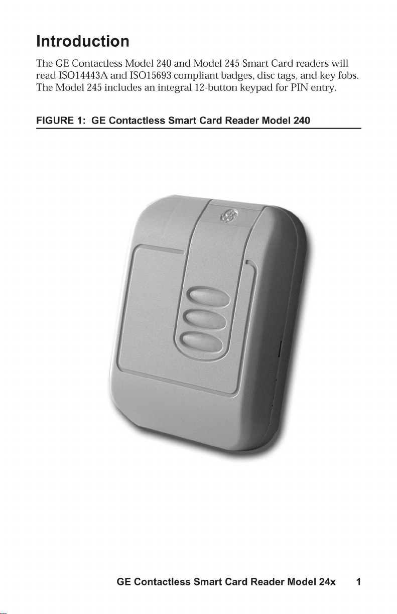

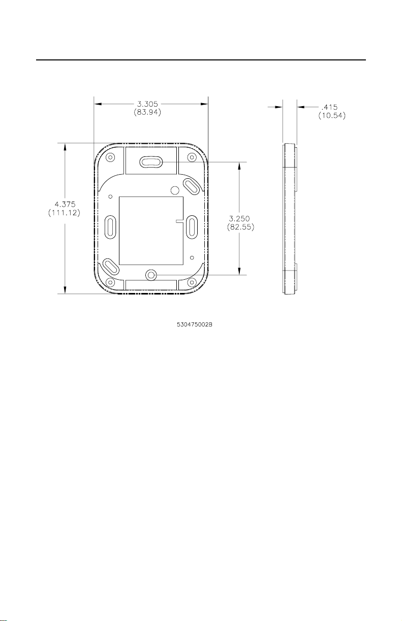
FIGURE 3: GE Model 24x Reader Backplate (includes tamper switch
magnet)
Note: Mounting holes fit standard US single-width electrical box and
standard European (EMEA) electrical box hole patterns.
An IsolationSpacer (shown in Figure 4) may be used to improve the readrange distance when mounting to metal surfaces. Dimensions are the
same as the Reader Backplate.
GE Contactless Smart Card Reader Model 24x 3
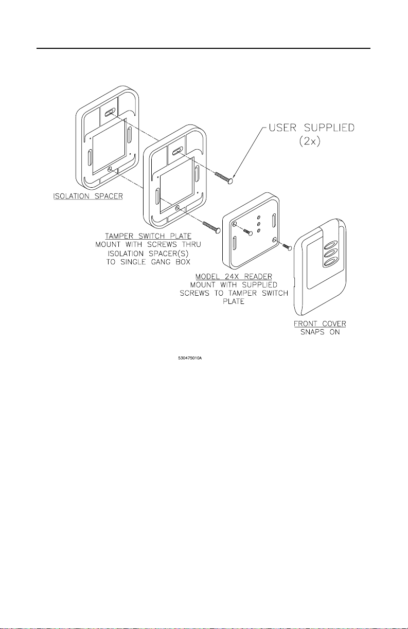
FIGURE 4: Isolation Spacer
4 GE Contactless Smart Card Reader Model 24x

Product Overview
Features
• Universal compatibility with all ISO 15963 and ISO 14443A
credentials (badges, disc tags, and key fobs).
• Supervised four-state (open, closed, wire cut, and wire short)
monitoringfordoorcontacts,REX(requesttoexit).
• Electrical protection (reverse polarity diode protection on power
lines).
• Data lines; high-speed transient voltage suppressor diodes
• Compatible with Micro/5 2RP and 8RP Reader Processor boards,
Micro/PX-2000, and Micro/PXN-2000 controllers
• IP 65-rated sealed electronics for deployment in both interior and
exterior environments.
• Integrated reader tamper protection and supervised data
communications.
• Reads the serial BID (badge ID) number of all ISO 15693 and ISO
14443A credentials.
• 12-button tactile membrane keypad (3 x 4 matrix) for PIN (personal
identification number) entry (Model 245 only).
• RS-485 communications for reader firmware maintenance operations.
Access Control System Compatibility
The Model 24x badge reader outputsa 16-digitbadge identification(BID)
number. As a result, the Model 24x Smart Card Readers are compatible
with Picture Perfect while microcontrollers on a Secure Perfect system
must be field-configured for Model 24x compatibility.
Picture Perfect Edition Setup
Refer to Access/Badge Formats or to the Picture Perfect online help for
assistance. A 16-digit BID format must be defined within Picture Perfect.
Enter a suitable badge format description. Example:
and define the format: %16S.
Secure Perfect Edition Setup
The Secure Perfect Edition access control system supports Badge IDs
(BIDs) up to a maximum of 12-digits. Since the Model 24x readers output
a 16-digit BID number, the Secure Perfect host controller/
GE Contactless Smart Card Reader Model 24x 5
16-digit BID