


mini
Wiring & Installation
Instructions
V06/05/08

proxSafe mini
mini
© Copyright 2008 by deister electronic GmbH
All rights reserved. No part of this publication may be reproduced, stored in a retrieval
system, or transmitted, in any form or by any means, electronic, mechanical, photocopying,
recording, or otherwise, without prior written permission of deister electronic GmbH.
deister electronic GmbH reserves the right to make changes to any and all parts of this
documentation without obligation to notify any person or entity of such changes.
May 2008 JR/IO/BF
deister electronic GmbH
Hermann-Bahlsen Str. 11
30890 Barsinghausen
Germany
Phone: +49 (0) 51 05 - 51 61 11
Fax: +49 (0) 51 05 - 51 62 17
E-Mail: info@deister-gmbh.de
Web: www.deister.com
2 ps_mini_wi_en 29/05/08

proxSafe mini
mini
Contents
1. Technical data ........................................................ 4
1.1 Electrical characteristics..................................................................................4
1.2 Housing .......................................................................................................4
1.3 Customer interfaces.......................................................................................5
1.3.1 Communication ............................................................................................5
1.3.2 Power........................................................................................................... 6
1.4 Relay............................................................................................................6
1.5 Battery.......................................................................................................... 7
2. Wiring diagram......................................................7
2.1 Signalisation .................................................................................................7
2.2 Configuration ...............................................................................................7
2.3 Air interface ..................................................................................................7
3. General .................................................................. 8
4. Implementing hints ................................................ 9
5. Shutter is blocked................................................... 9
6. Emergency unlock ................................................10
7. Regulatory notices................................................ 13
7.1 Europe .......................................................................................................13
7.2 FCC Digital Device Limitations......................................................................13
V29/05/08 ps_mini_wi_en 3
proxSafe mini
mini
1. Technical data
1.1 Electrical characteristics
UB: 12-13,8V/DC*
In: 50mA (Standby)
Imax: 2,3A (during closing or opening, if no other components activated)
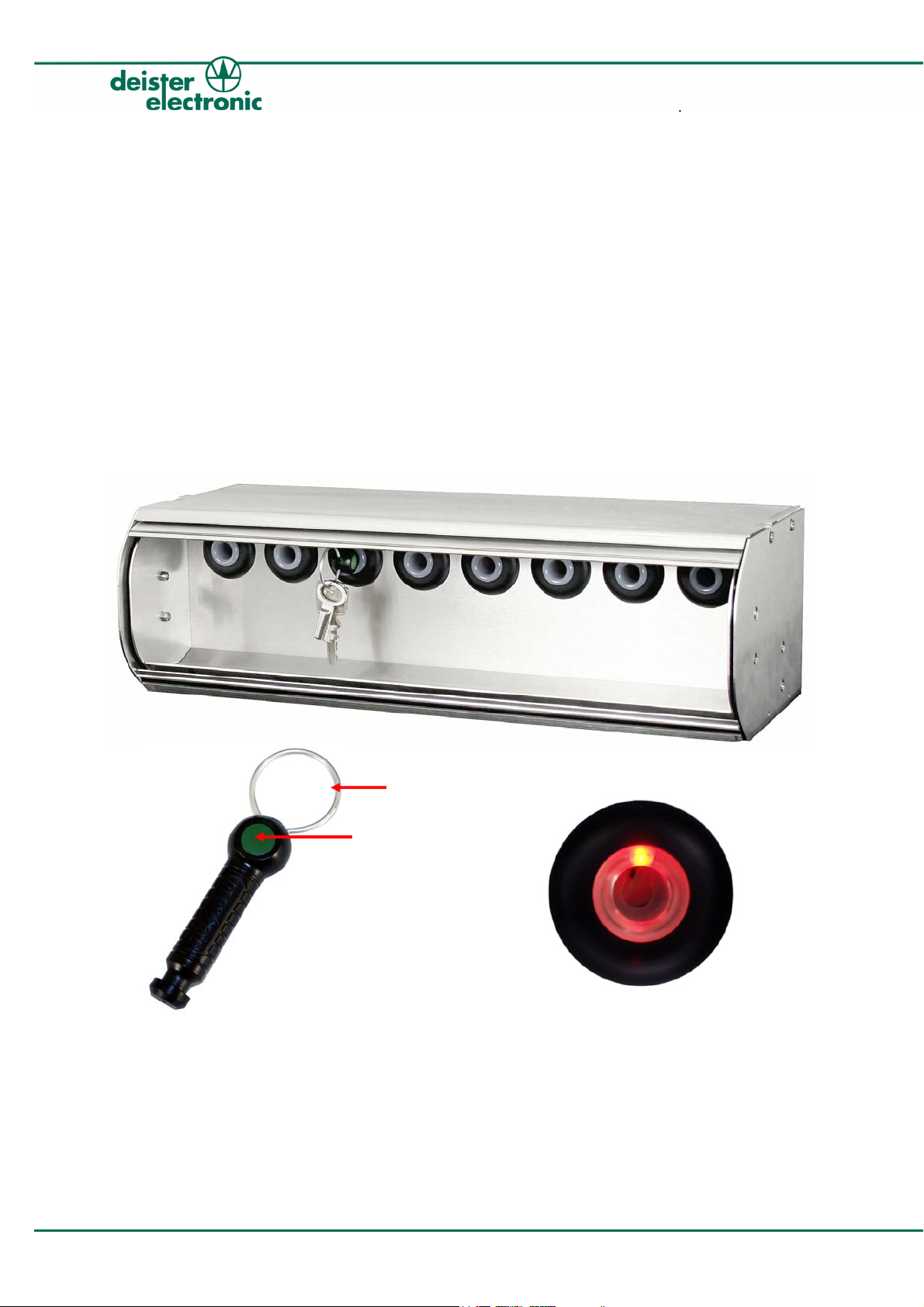
1.2 Housing
Width: 440mm without mounting angle
484mm with mounting angle
Height: 133mm
Depth: 173mm
keyTag proxCylinder
* 13,8 V needed if a battery is connected and needs to be charged
12 V if no battery charging is required.
This refers to all voltages in the manual.
keyRing
Seal
4 ps_mini_wi_en 29/05/08
proxSafe mini
mini
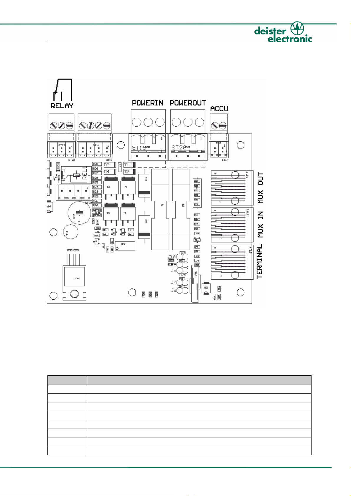
1.3 Customer interfaces
Figure 1: interfaces
1.3.1 Communication
RS485 deBus, 9600 Baud, 1 startbit, no parity, 1 stopbit, 8 bits
RJ45 Connector
Connect TERMINAL of the multiplexer to HOST (e.g. via SNG3)
Pin Description
1
2 nc
3 GND
4 GND
5 +UB (13ss,8V)
6 +UB (13,8V)
7 RS485 B
8 RS485 A
nc
V29/05/08 ps_mini_wi_en 5

MUX IN: Data line from previous multiplexer
Pin Description
1
2 nc
3 GND
4 GND
5 +UB (13,8V)
6 +UB (13,8V)
7 RS485 B
8 RS485 A
MUX OUT: Data line to next multiplexer
Pin Description
1
2 nc
3 GND
4 GND
5 +UB (13,8V)
6 +UB (13,8V)
7 RS485 B
8 RS485 A
1.3.2 Power
nc
nc
proxSafe mini
mini
3-PinConnector, green RM5
POWER IN: Power line from previous multiplexer or from power supply
Pin Description
1
2 13,8V
3 GND
3-Pin Connector, green RM5
POWER OUT: Power line to next multiplexer
Pin Description
1
2 13,8V
3 GND
nc
nc
1.4 Relay
3-Position Field Wiring Connector, green RM3.5
(see Figure 1)
6 ps_mini_wi_en 29/05/08

proxSafe mini
mini
1.5 Battery
2-Pin Field Wiring Connector, Battery
Pin Description
1
2 GND
ACCU +
2. Wiring diagram
The deBus supports a maximum of 32 devices. The amount of necessary power supplies is
depending on the application (e.g. if shutters are used or not). In this example an SNG3
adapter is used to connect the data line to the HOST.
MUX
MUX
2.1 Signalisation
TERMINAL
MUX IN
MUX OUT
POWERIN
POWEROUT
TERMINAL
MUX IN
MUX OUT
POWERIN
POWEROUT
Power supply
12-13,8V/DC, 3A
Local MUX
proxSafe
SN
USB
HOST
Beeper internal
Red LED internal
Green LED internal
Yellow LED internal
2.2 Configuration
Only device address is configurable (see deBus description).
Possible device addresses: 0x22,0x23,0x25...0x2F,0x41...0x4F,0x51,0x52
0x21 is standard address on delivery.
2.3 Air interface
Frequency: 125KHz
Bitrate: 4Kbit
V29/05/08 ps_mini_wi_en 7

3. General
proxSafe mini is part of a keyTag management system.
With proxSafe mini you can handle up to 8 proxCylinders in one device.
Connection of the proxCylinders is done by RJ45 connectors.
Each proxCylinder contains of the following devices:
• Relay for keyTag release
• Coil for keyTag identification
• Red LED for optical signalisation
• End switch for detecting, if the proxCylinder is occupied
UB: 13,8V/DC
proxSafe has a serial interface for communication:
RS485, 9600 Baud, no parity, 1 stopbit, 8 bits
Protocol: deBus
The following parts of the proxSafe can be controlled by the host:
• Beeper
• Yellow LED
• Red LED main board
• Red LEDs proxCylinders
• Relay proxCylinders
• Lock
• Motor
Following states are controlled by the main board:
• Tamper
• Low voltage
• Device alert (shutter blocked)
• Status lock
• Status cabinet (open, closed, in move or undefined)
• Status end switch top
• Status end switch bottom
• Voltage on antenna of the proxCylinders
(only after reset or after command “Get Image”)
proxSafe mini
mini
8 ps_mini_wi_en 29/05/08

proxSafe mini
mini
4. Implementing hints
You will find the implementing hints in the debus protocol for the proxsafe mini (available
on request).
5. Shutter is blocked
If the terminal gives a signal to the multiplexer to close the shutter and the shutter is blocked,
the multiplexer tries closing the shutter for three times. If the third attempt failed, the shutter
remains in this position. The device alert flag is set (see error codes in debus protocol
description). The beeper of the multiplexer is activated regularly for a short time. The beeper
can be deactivated by sending a “Set Output”-command with TIM = 0x00 and StdIo =
virtual beeper. The device alert flag is not influenced by this command. The device alert flag is
reset by sending the “Reset Status”-command or if the next closing of the shutter succeeds.
V29/05/08 ps_mini_wi_en 9
r
proxSafe mini
mini
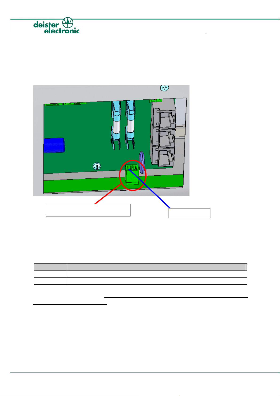
6. Emergency unlock
If normal operation failed (e.g. processor does not work) to get keys out, an emergency
unlock is integrated. The components for emergency unlock are at the backside of the
proxSafe mini.
The first step is to open the shutter. The shutter is protected against opening by hand.
For this reason in case of emergency the jack (red marked in the picture above) must be
connected to the emergency opening box with the 2-pole cable (enclosed) as follows in
order to unlock the shutter:
While the jack is connected and the switch of the emergency opening box is
being pressed constantly, the shutter can be opened by hand using a tool (for
example a screw driver).
Jack for unlocking the shutte
Pin1: GND
Pin Connection
1 GND
2 12-13,8V/DC
10 ps_mini_wi_en 29/05/08

proxSafe mini
mini
After the shutter has been opened this way, in a second step the emergency unlock for the
proxCylinders must now be activated separately as follows:
Jack for
emergency unlock
To activate this emergency unlock, the jack (red marked in the picture above) must be
connected to the emergency opening box with the 4-pole cable (enclosed) as follows:
Pin Connection
1 GND
2 12 -13,8V/DC
3 12 -13,8V/DC
4 12 -13,8V/DC
While this jack is connected and the switch of the emergency box is being
pressed constantly, all keys can be taken out.
Pin 1: GND
V29/05/08 ps_mini_wi_en 11
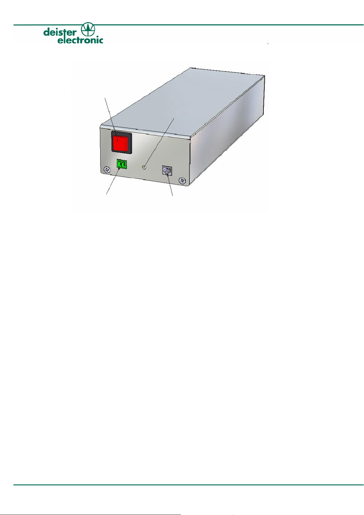
Emergency-switch
Emergency cable Battery charge
Battery status
proxSafe mini
mini
Emergency opening box with two different cables (one 2-pole-cable and one 4-pole cable)
12 ps_mini_wi_en 29/05/08

proxSafe mini
mini
7. Regulatory notices
7.1 Europe
Hereby, deister electronic GmbH declares that this equipment - if used according to the
instructions - is in compliance with the essential requirements and other relevant provisions of
the RTTE Directive 1999/5/ EC.
A complete declaration of conformity can be requested at:
info@deister-gmbh.de
Approved for use in all European countries.
7.2 FCC Digital Device Limitations
Radio and Television Interference
This equipment has been tested and found to comply with the limits for a Class A digital
device, pursuant to Part 15 of the FCC rules. These limits are designed to provide
reasonable protection against harmful interference when the equipment is operated in a
commercial environment. This equipment generates uses and can radiate radio frequency
energy and, if not installed and used in accordance with the instruction manual, may
cause harmful interference to radio communications. Operation of this equipment in a
residential area is likely to cause harmful interference, in which case the user will be
required to correct the interference at his own expense.
This device complies with Part 15 of the FCC rules. Operation is subject to the following
two conditions: (1) This device may not cause harmful interference, and (2) this device
must accept any interference received, including interference that may cause undesired
operation.
In order to maintain compliance with FCC regulations, shielded cables must be used with
this equipment. Operation with non-approved equipment or unshielded cables is likely to
result in interference to radio and television reception.
Caution! Changes or modifications not expressly approved by the manufacturer could
void the user’s authority to operate this equipment.
V29/05/08 ps_mini_wi_en 13

proxSafe mini
mini
7.3 FCC Notice
To comply with FCC part 15 rules in the United States, the system must be professionally
installed to ensure compliance with the Part 15 certification. It is the responsibility of the
operator and professional installer to ensure that only certified systems are deployed in
the United States. The use of the system in any other combination (such as co-located
antennas transmitting the same information) is expressly forbidden.
7.4 Industry Canada
This Class A digital apparatus complies with Canadian ICES-003.
Cet appareil numérique de la classe A est conforme à la norme NMB-003 du Canada.
14 ps_mini_wi_en 29/05/08

proxSafe mini
mini
Notes:
V29/05/08 ps_mini_wi_en 15

Notes:
proxSafe mini
mini
16 ps_mini_wi_en 29/05/08

x
proxSafe mini
mini
Germany:
deister electronic GmbH
Hermann-Bahlsen Str. 11
30890 Barsinghausen
Tel.: +49 (0) 51 05 - 51 61 11
Fax: +49 (0) 51 05 - 51 62 17
info@deister-gmbh.de
www.deister.com
Belgien & Lu
deister electronic office
Business Park E 19
Battelsesteenweg 455/A
2800 Mechelen
Tel.: +32 (0) 15 - 28 09 68
Fax: +32 (0) 15 - 28 09 71
info@benelux.deister.com
Frankreich:
deister electronic france
101 rue Pierre Semard
92320 Chatillon
Tel.: +33 (0) 1 47 - 35 78 78
Fax: +33 (0) 1 47 - 35 92 59
info@deister.fr
Großbritannien:
deister electronic (UK) Ltd.
Stapleton Way, Enterprise Park
Spalding, Lincolnshire
PE11 3YQ
Tel.: +44 (0) 1775 - 717100
Fax: +44 (0) 1775 - 717101
info@deister.co.uk
Niederlande:
deister electronic office
Tolnasingel 3
2411 PV Bodegraven
Tel.: +31 (0) 1726 - 32970
Fax: +31 (0) 1726 - 32971
info@nl.deister.com
V29/05/08 ps_mini_wi_en 17
emburg:
Kanada:
Deister Electronics Inc.
1099 Kingston Road, Suite 212
Pickering, ON L1V 1B5
Tel.: +1 905 - 837 5666
Fax: +1 905 - 837 0777
info@deister-electronic.com
Japan:
deister electronic Japan, LTD.
Toshiba Hoshikawa Bldg. 4F
2-4 Kawabe-chô
Hodogaya-ku, Yokohama-shi
Kanagawa, 240-0001
Tel.: +81 (0) 45 340 1831
Fax: +81 (0) 45 340 1801
info@deister.jp
USA:
Deister Electronic USA, Inc.
9303 Grant Avenue
Manassas, VA 20110
Tel.: +1 703 - 368 2739
Fax: +1 703 - 368 9791
info@deister.com
 Loading...