

DEI Headquarters HYU1800 User Manual
REMOTE STARTER SYSTEM FOR
AUTOMATIC TRANSMISSION ONLY
DRAFT
Special programming procedure for vehicles that
may not have a Tach source.
FCC USER NOTICE:
This device complies with Part 15 of the FCC Rules. Operation is subjec t to the following tw o conditions : (1) this dev ice may n ot cause harmful interference, and
(2) this device must accept any interference received, including interference that may cause undesired operation.
NOTE: The manufacturer is not responsible for any radio or TV interfere nce caused by unauth orized modifications to th is equipment. Such mo difications could
void the user's authority to operate the equipment.
IMPORTANT NOTICE
Page-1

TABLE OF CONTENT
GOVERNMENT REGULATIONS .......................................................................................................................................... 3
GENERAL ............................................................................................................................................................................. 3
General service information ............................................................................................................................................... 3
MAKING YOUR CONNECTIONS .......................................................................................................................................... 4
Preparation ........................................................................................................................................................................ 4
Connections ....................................................................................................................................................................... 5
Alternative methods of making your connections ............................................................................................................... 6
PREPARATION ..................................................................................................................................................................... 7
Panel removal .................................................................................................................................................................... 7
MAIN IGNITION HARNESS .................................................................................................................................................. 9
5-PIN ACCESSORY HARNESS .......................................................................................................................................... 10
Ground input (-) (Black wire) ............................................................................................................................................ 10
Tach input (AC) (Purple wire) .......................................................................................................................................... 11
Hood switch input (-) (Grey wire) ..................................................................................................................................... 12
Brake switch input (+) (Orange wire) ............................................................................................................................... 13
3-PIN HARNESS ................................................................................................................................................................. 14
Parking lights output (-) (Yellow/White wire) .................................................................................................................... 14
Rearm output (-) (Blue/White wire) .................................................................................................................................. 15
IMMOBILIZER INTERFACE MODULE ............................................................................................................................... 16
Transponder T-harness ................................................................................................................................................... 16
IMMOBILIZER INTERFACE MODULE ............................................................................................................................... 17
Ignition interrupt ............................................................................................................................................................... 17
Ignition Interrupt wiring schematic ................................................................................................................................... 18
BCM connector M04-B removed ....................................................................................................................................... 20
ANTENNA INSTALLATION ................................................................................................................................................ 21
FINISHING THE INSTALLATION ........................................................................................................................................ 22
Connecting the harness to the remote starter module ..................................................................................................... 22
FINISHING THE INSTALLATION ........................................................................................................................................ 23
Connecting the harness to the immobilizer interface module ........................................................................................... 23
PROGRAMMING ................................................................................................................................................................. 24
Programming of the remote starter transmitters .............................................................................................................. 24
PROGRAMMING ................................................................................................................................................................. 25
Remote starter tachometer learning procedure ............................................................................................................... 25
PROGRAMMING ................................................................................................................................................................. 26
Programming the immobilizer interface ........................................................................................................................... 26
TESTING AND CLOSING UP ............................................................................................................................................. 27
Testing ............................................................................................................................................................................. 27
TESTING AND CLOSING UP ............................................................................................................................................. 28
Closing up ........................................................................................................................................................................ 28
Page-2

GOVERNMENT REGULATIONS
This device complies with part 15 of the FCC Rules. Operation is subject to the following two conditions: (1) This device
may not cause harmful interference, and (2) this device must accept any interference received, including interference that
may cause undesired operation.
This equipment has been tested and found to comply with the limits for a Class B digital device, pursuant to part 15 of the
FCC Rules. These limits are designed to provide reasonable protection against harmful interference in a residential
installation. This equipment generates and can radiate radio frequency energy and, if not installed and used in accordance
with the instructions, may cause harmful interference to radio communications. However, there is no guarantee that
interference will not occur in a particular installation. If this equipment does cause harmful interference to radio or television
reception, which can be determined by turning the equipment off and on, the user is encouraged to try to correct the
interference by one or more of the following measures:
• Reorient or relocate the receiving antenna.
• Increase the separation between the equipment and receiver.
• Connect the equipment into an outlet on a circuit different from that to which the receiver is connected.
• Consult the dealer or an experienced radio/TV technician for help.
This device complies with the Industry Canada Radio Standards Specification RSS 210. Its use is authorized only on a nointerference, no-protection basis; in other words, this device must not be used if it is determined that it causes harmful
interferences to services authorized by IC. In addition, the user of this device must accept any radio interface that may be
received, even if this interference could affect the operation of the device.
Warning:
Changes or modifications not expressly approved by the party responsible for compliance could void the user’s authority to
operate this device.
GENERAL
General service information
Installation points to remember
• Always make sure to cover fenders, seats, and floor areas before starting to work.
• When working on a vehicle, always roll down a window to avoid being locked out of the car.
• Always make all of the necessary connections BEFORE plugging in the module.
• Never install the control unit where it could interfere with normal operation or obstruct service technicians.
• Airbag wires are not always labelled (i.e. yellow split loom/tubing) on the harness itself, but will always be
labelled at the connector plugs where they terminate.
• Make sure that all safety equipments – i.e., the hood switch and the warning label -- are installed.
Page-3

•
Preparation of tools and measuring equipment
Ensure that all of the necessary information, material, tools and measuring equipment are available before beginning the
installation.
Tools needed to perform the installation:
• Philips tip screwdriver
• ¼” drive ratchet
• ¼” drive ratchet extension
• ¼” drive 10 MM socket
• Miniature pick set
• Wire stripper
• Utility knife / blade
• Multimeter
• Trim pad remover
• Hyundai GDS or HI-SCAN tool
• Soldering iron
Information needed to perform the installation:
• Obtain the vehicle’s 6-digit PIN number by either
contacting Hyundai’s tech line or using the online
service.
Material needed to perform the installation:
• Tie-WRAP / cable ties
• Black electrical tape
Wire solder
MAKING YOUR CONNECTIONS
Preparation
1.
Locate and test the wire with the appropriate measurement tool.
2.
Using your wire stripper, make two incisions in the wire insulation, approximately 3.8 cm (1.5 inch) apart from each other.
Make sure not to cut any of the wire strands.
3.
Using your utility knife / blade, remove the top part of the insulation to expose the wire strands.
4.
Completely remove the wire insulation between the incisions.
Page-4
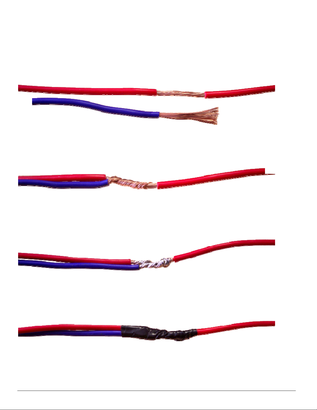
Connections
We strongly recommend soldering all of the remote starter connections that are not done with the T-harness provided.
1.
Cut the wire you wish to connect to the right length and remove approximately 3.8 cm (1.5 inch) of insulation at its end
(B).
B
2.
Twist the wire (B) around, making sure to expand the connection pad to the entire length of the exposed part of the source
wire (A).
A
3.
Solder the connection, making sure to properly heat both wires beforehand.
4.
Use electrical tape to isolate your connection. Ensure you let the wires cool down from the soldering process before you
proceed, so as to avoid melting the electrical tape.
B
Page-5
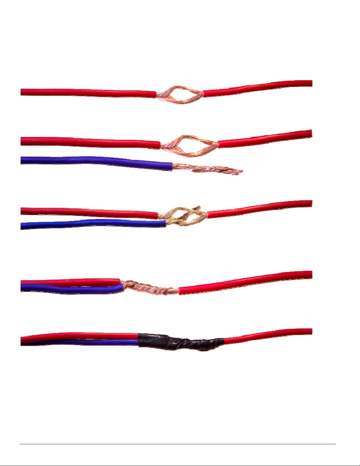
Alternative methods of making your connections
The `”poke and twist” method can also be used for connecting wires.
1.
Using a sharp point tool (i.e., a straight pick), separate the wire strands in two.
2.
Cut the wire you wish to connect to the right length and remove approximately 3.8 cm (1.5 inch) of insulation at its end.
3.
Insert the wire you wish to connect in the middle of the “LOOP” part of the source wire.
4.
Twist the wire around, making sure to expand the connection pad to the entire length of the exposed part of the source
wire.
5.
Use electrical tape to isolate your connection. Make sure that there are no wire strands going through the electrical tape.
Page-6
PREPARATION
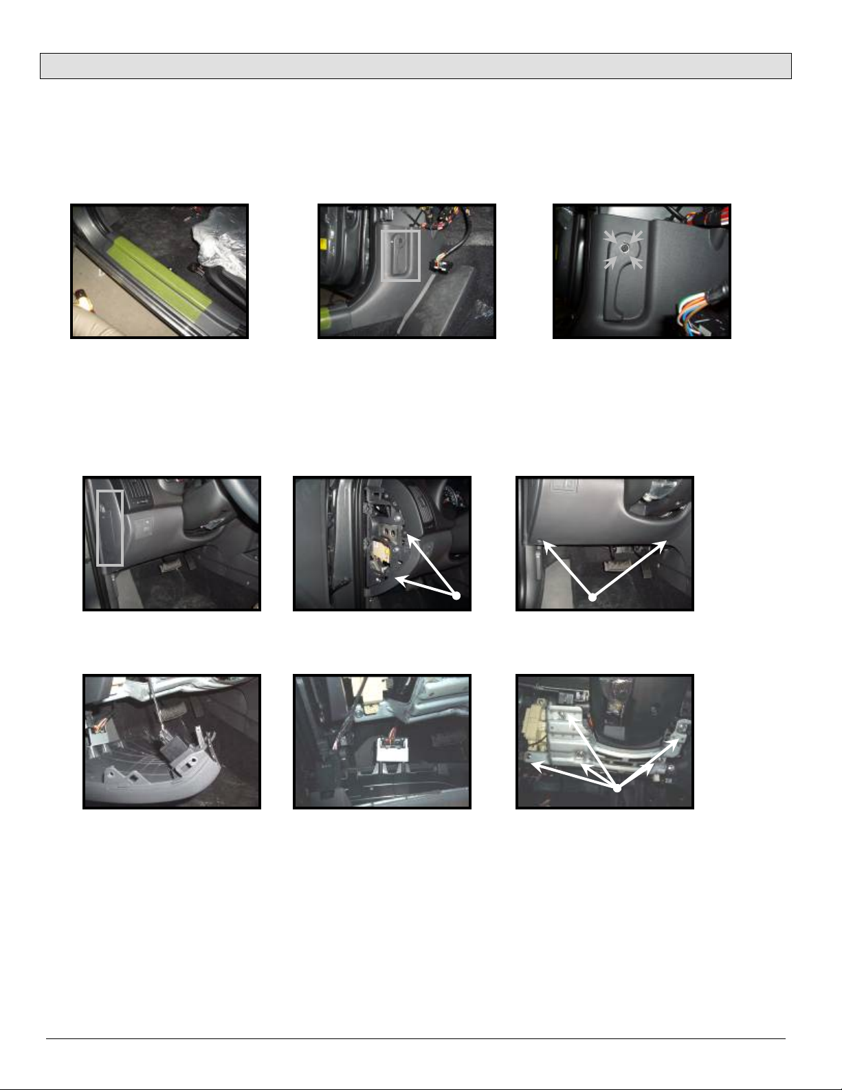
Panel removal
Completely remove the driver’s running board (Picture A) and driver’s kick panel. You must first remove the hood release
handle by unscrewing the Philips screw in the centre part and lightly pulling on the handle (Pictures B and C).
Remove the crash panel side cover (Picture D); unscrew the four (4) Philips screws (Pictures E, F). Pull lightly on the
panel, making sure to disconnect the data link and other control switch connectors on the lower dash (Pictures G and H).
Unscrew the 5X 10 mm bolts retaining the metal crash bolster (Picture I).
Picture A Picture B
Picture D Picture E
Picture C
Picture F
Picture G Picture H
Picture I
Page-7
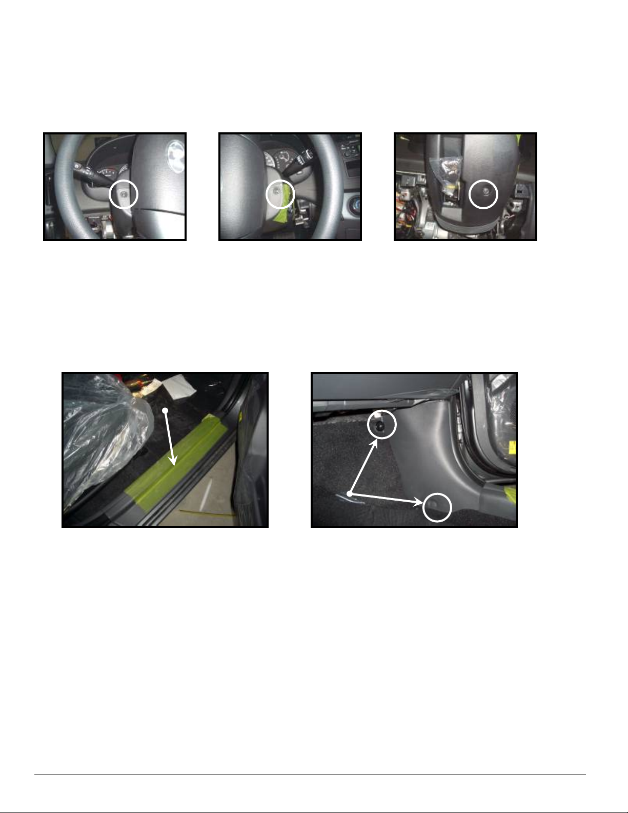
Panel removal
Remove the three (3) Philips screw holding the steering column shroud located on the left (picture J) and right (picture
K) and also on the bottom (Picture L) of the steering column, once the screws are removed gently separate the top half
from the bottom half and completely remove the bottom half of the steering column shroud.
Loosen the passenger running board (Picture M) and pull lightly to remove it. Remove the two (2) clips retaining the
passenger kick panel and remove it (Picture N).
Picture J Picture K
Picture L
Picture M
Picture N
Page-8
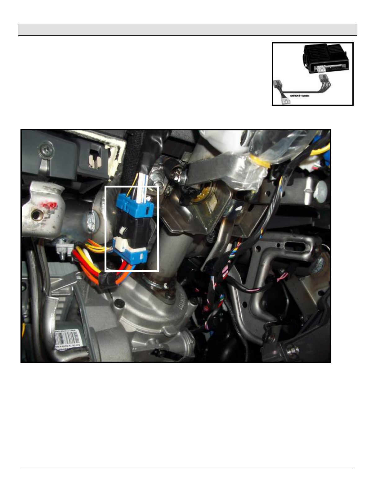
MAIN IGNITION HARNESS
At the vehicle ignition switch, disconnect the harness located at the left of the steering
column (Pictures O). Connect the main ignition T-harness (Fig 1) between the
vehicle’s harnesses you just disconnected. Run the T-harness to the left of the
steering column and secure it with a tie wrap.
FIG 1
Picture O
Page-9
 Loading...