


DRAFT
Model 7900
DRAFT
Installation Guide
NOTE: This product is intended for installation by a professional installer only!
Any attempt to install this product by any person other than a trained professional
may result in severe damage to a vehicle’s electrical system and components.
© 2006 Directed Electronics, Vista, CA
N5501V 10-06

DRAFT
Bitwriter®, Code Hopping™, Doubleguard®, ESP™, FailSafe®, Ghost Switch™, Learn Routine™, Nite-
DRAFT
Lite®, Nuisance Prevention® Circuitry, Revenger®, Silent Mode™, Soft Chirp®, Stinger®, Valet®,
Vehicle Recovery System®, VRS®, and Warn Away® are all Trademarks or Registered Trademarks of
Directed Electronics.
The Bitwriter® (p/n 998T)
requires chip version 2.2 or
newer to program this unit.
New Software Compatibility for
103T Keypad
This unit now has software that
allows arming with entry delay when
used in conjunction with the optional
103T Keypad. Refer to the 103T
Owner’s Guide for details.
2 © 2005 Directed Electronics—all rights reserved

DRAFT
table of contents
DRAFT
what is included . . . . . . . . . . . . . . . . . . . . . . . . . . .4
warning! safety first . . . . . . . . . . . . . . . . . . . . . . . .4
installation points to remember . . . . . . . . . . . . . . .5
before beginning the installation . . . . . . . . . . . . . 5
after the installation . . . . . . . . . . . . . . . . . . . . .5
deciding on component locations . . . . . . . . . . . . . .6
locations for the siren . . . . . . . . . . . . . . . . . . . . 6
locations for the control module . . . . . . . . . . . . . 6
locations for stinger doubleguard shock sensor . . .7
mounting the antenna . . . . . . . . . . . . . . . . . . . . 7
locations for valet/program switch . . . . . . . . . . . . 8
locations for the status LED . . . . . . . . . . . . . . . .8
finding the wires you need . . . . . . . . . . . . . . . . . . .9
locations for the optional starter kill relay . . . . . .9
locations for the relay satellite . . . . . . . . . . . . . . 9
obtaining constant 12V . . . . . . . . . . . . . . . . . . .9
finding the 12V switched ignition wire . . . . . . . . 10
finding the starter wire . . . . . . . . . . . . . . . . . . 10
finding the tachometer wire . . . . . . . . . . . . . . . 11
finding the accessory wire . . . . . . . . . . . . . . . . 11
finding the wait-to-start bulb wire for diesels . . . 11
finding a (+) parking light wire . . . . . . . . . . . . . 12
finding the door pin switch circuit . . . . . . . . . . . 12
making your wiring connections . . . . . . . . . . . . . .13
primary harness (H1), 12-pin connector . . . . . . . .14
auxiliary harness (H2), 6-pin connector . . . . . . . . .14
door lock harness, 3-pin connector . . . . . . . . . . . .15
remote start ribbon harness, wiring diagram . . . . .15
heavy gauge inline connector key switch interface .16
remote start harness (H3), 5-pin connector . . . . . .16
horn, channel 6 (H4), 2-pin connector . . . . . . . . .16
relay satellite wire connection guide . . . . . . . . . . .23
remote start secondary harness (H3) wire . . . . . . . . .
connection guide . . . . . . . . . . . . . . . . . . . . . . . . . 24
horn, channel 6 harness (H4) wire connection guide 26
neutral safety switch interface . . . . . . . . . . . . . . . 26
testing the neutral safety switch . . . . . . . . . . . . 27
bypassing GM vehicle anti-theft systems (VATS) . . . 29
1995 and newer vehicle anti-theft systems . . . . . . . .
(immobilizers) . . . . . . . . . . . . . . . . . . . . . . . . . . .30
passlock I and passlock II (PL-1 and PL-2) . . . . . 30
passkey III (PK-3), transponder-based systems . . 30
plug-in LED and valet/program switch . . . . . . . . . .31
programmer interface, 3-pin black plug . . . . . . . . .31
shock sensor harness, 4-pin connector . . . . . . . . . .32
tach learning . . . . . . . . . . . . . . . . . . . . . . . . . . . .32
programming jumpers . . . . . . . . . . . . . . . . . . . . . .33
tach threshold on/off . . . . . . . . . . . . . . . . . . . . 33
light flash (+)/(-) . . . . . . . . . . . . . . . . . . . . . . 33
transmitter/receiver learn routine™ . . . . . . . . . . . .34
standard configuration . . . . . . . . . . . . . . . . . . . 36
remote control diagram . . . . . . . . . . . . . . . . . . . . .37
standard mode configuration . . . . . . . . . . . . . . . . .38
multi-level security arming . . . . . . . . . . . . . . . . . .39
system features learn routine . . . . . . . . . . . . . . . .40
feature menus . . . . . . . . . . . . . . . . . . . . . . . . . . .42
menu #1 - basic features . . . . . . . . . . . . . . . . . 42
menu #2 - advanced features. . . . . . . . . . . . . . . 43
menu #3 - remote start options . . . . . . . . . . . . . 44
feature descriptions . . . . . . . . . . . . . . . . . . . . . . .45
menu #1 - basic features . . . . . . . . . . . . . . . . . 45
menu #2 - advanced features. . . . . . . . . . . . . . . 46
menu #3 - remote start options . . . . . . . . . . . . . 49
valet mode . . . . . . . . . . . . . . . . . . . . . . . . . . . . . .51
rear defogger control . . . . . . . . . . . . . . . . . . . . . .51
timer mode . . . . . . . . . . . . . . . . . . . . . . . . . . . . .52
table of zones . . . . . . . . . . . . . . . . . . . . . . . . . . . 53
shutdown diagnostics . . . . . . . . . . . . . . . . . . . . . .53
to perform shutdown diagnostics . . . . . . . . . . . . 53
long term event history . . . . . . . . . . . . . . . . . . . .54
safety check . . . . . . . . . . . . . . . . . . . . . . . . . . . .54
troubleshooting . . . . . . . . . . . . . . . . . . . . . . . . . .55
alarm troubleshooting . . . . . . . . . . . . . . . . . . . 55
remote start troubleshooting . . . . . . . . . . . . . . . 56
wiring quick reference guide . . . . . . . . . . . . . . . . . 58
relay satellite wiring quick reference guide . . . . . .59
© 2005 Directed Electronics—all rights reserved 3

DRAFT
what is included
DRAFT
■ The control module ■ The plug-in status LED
■ A Responder receiver/antenna ■ The plug-in Valet/Program switch
■ One 2-way Color Remote Control P/N 7541V ■ A hood pinswitch
■ A Stinger Doubleguard shock sensor ■ A toggle (override) switch
■ A 514N Neosiren ■ One Remote Control car charger
warning! safety first
The following safety warnings must be observed at all times:
■ Due to the complexity of this system, installation of this product must only be performed by an authorized
Directed Electronics dealer.
■ When properly installed, this system can start the vehicle via a command signal from the remote control
transmitter. Therefore, never operate the system in an area that does not have adequate ventilation. The
following precautions are the sole responsibility of the user; however, authorized Directed Electronics dealers
should make the following recommendations to all users of this system:
1. Never operate the system in an enclosed or partially enclosed area without ventilation (such as a
garage).
2. When parking in an enclosed or partially enclosed area or when having the vehicle serviced, the remote
start system must be disabled using the installed toggle switch.
3. It is the user's sole responsibility to properly handle and keep out of reach from children all remote
control transmitters to assure that the system does not unintentionally remote start the vehicle.
4. THE USER MUST INSTALL A CARBON MONOXIDE DETECTOR IN OR ABOUT THE LIVING AREA ADJACENT
TO THE VEHICLE. ALL DOORS LEADING FROM ADJACENT LIVING AREAS TO THE ENCLOSED OR PARTIALLY
ENCLOSED VEHICLE STORAGE AREA MUST AT ALL TIMES REMAIN CLOSED.
■ Use of this product in a manner contrary to its intended mode of operation may result in property damage,
personal injury, or death. Except when performing the Safety Check outlined in this installation guide, (1)
Never remotely start the vehicle with the vehicle in gear, and (2) Never remotely start the vehicle with the
keys in the ignition. The user will be responsible for having the neutral safety feature of the vehicle periodi-
cally checked, wherein the vehicle must not remotely start while the car is in gear. This testing should be
performed by an authorized Directed Electronics dealer in accordance with the Safety Check outlined in this
product installation guide. If the vehicle starts in gear, cease remote start operation immediately and consult
with the user to fix the problem immediately.
4 © 2005 Directed Electronics—all rights reserved

DRAFT
fcc/id notice
DRAFT
This device complies with Part 15 of FCC rules. Operation is subject to the following two conditions: (1)
This device may not cause harmful interference, and (2) This device must accept any interference received,
including interference that may cause undesirable operation.
Changes or modifications not expressly approved by the party responsible for compliance could void the user's
authority to operate this device.
caution
This product is designed for fuel injected, automatic transmission vehicles only. Use of this product in a standard
transmission vehicle is dangerous and contrary the product's intended use.
© 2005 Directed Electronics—all rights reserved 5

DRAFT
■ After the remote start module has been installed, test the remote start module in accordance with the
DRAFT
Safety Check outlined in this installation guide. If the vehicle starts when performing the Neutral Safety
Shutdown Circuit test, the remote start unit has not been properly installed. The remote start module must
be removed or properly reinstalled so that the vehicle does not start in gear. All installations must be per-
formed by an authorized Directed Electronics dealer. OPERATION OF THE REMOTE START MODULE IF THE
VEHICLE STARTS IN GEAR IS CONTRARY TO ITS INTENDED MODE OF OPERATION. OPERATING THE REMOTE
START SYSTEM UNDER THESE CONDITIONS MAY RESULT IN PROPERTY DAMAGE OR PERSONAL INJURY.
IMMEDIATELY CEASE THE USE OF THE UNIT AND REPAIR OR DISCONNECT THE INSTALLED REMOTE START
MODULE. DIRECTED ELECTRONICS, INC. WILL NOT BE HELD RESPONSIBLE OR PAY FOR INSTALLATION OR
REINSTALLATION COSTS.
installation points to remember
IMPORTANT! This product is designed for fuel-injected, automatic transmission vehicles only.
Installing it in a standard transmission vehicle is dangerous and is contrary to its intended use.
before beginning the installation
■ Please read this entire installation guide before beginning the installation. The installation of this remote
start system requires interfacing with many of the vehicle’s systems. Many new vehicles use low-voltage or
multiplexed systems that can be damaged by low resistance testing devices, such as test lights and logic
probes (computer safe test lights). Test all circuits with a high quality digital multi-meter before making con-
nections.
■ Do not disconnect the battery if the vehicle has an anti-theft-coded radio. If equipped with an air bag,
avoid disconnecting the battery if possible. Many airbag systems will display a diagnostic code through their
warning lights after they lose power. Disconnecting the battery requires this code to be erased, which can
require a trip to the dealer.
■ Check with the customer on status LED location.
■ Remove the domelight fuse. This prevents accidentally draining the battery.
■ Roll down a window to avoid being locked out of the car.
after the installation
■ Test all functions. The “Using Your System” section of the Owner's Guide is very helpful when testing.
■ When testing, don’t forget that this system is equipped with Nuisance Prevention® Circuitry (NPC). NPC can
bypass trigger zones, making them appear to stop working. See the Nuisance Prevention® Circuitry section.
■ Review and complete the Safety Check section of this guide prior to the vehicle reassembly.
6 © 2005 Directed Electronics—all rights reserved
DRAFT
deciding on component locations
DRAFT
locations for the siren
Some things to remember about mounting the siren:
■ Keep it away from heat sources, such as radiators, exhaust manifolds, turbochargers, and heat shields.
■ Mount it where a thief cannot easily disconnect it, whether the hood is open or shut. Both the siren and its
wires should be difficult to find. This usually in volves disguising the wire to look like a factory harness.
■ We recommend against grounding the siren to its mounting screws. Instead, we recommend running both
the red and black wires into the passenger compartment and grounding to one common point for all devices.
After all, both wires are the same length and come already bonded together. Whenever possible, conceal your
wires in the factory har ness es or in the same style loom as the factory.
■ When possible, place the siren on the same side of the vehicle as the control module, where its wires will
reach the control module’s wires without extending them. Always run the wires through the center of a
grommet, never through bare metal!
■ Point the siren down so water does not collect in it.
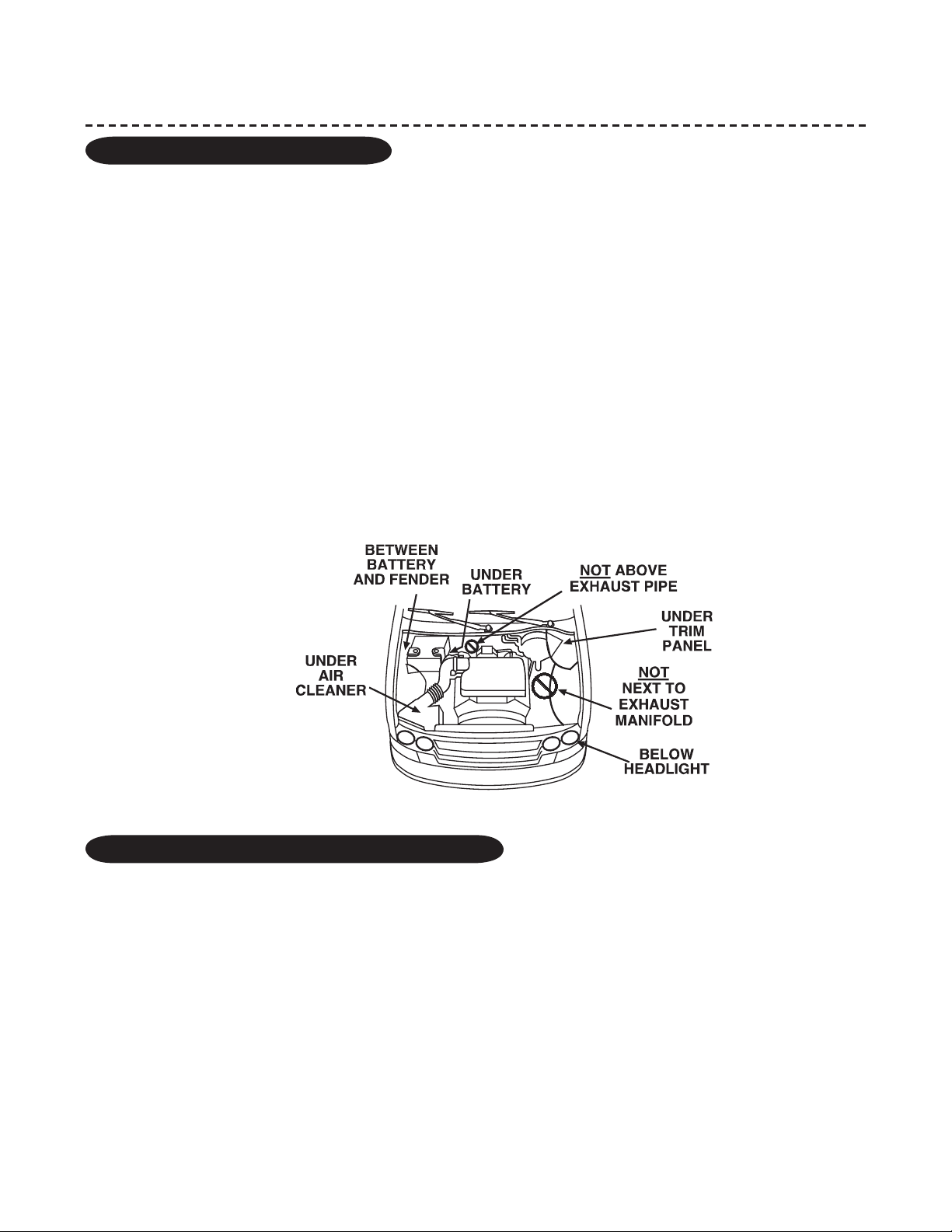
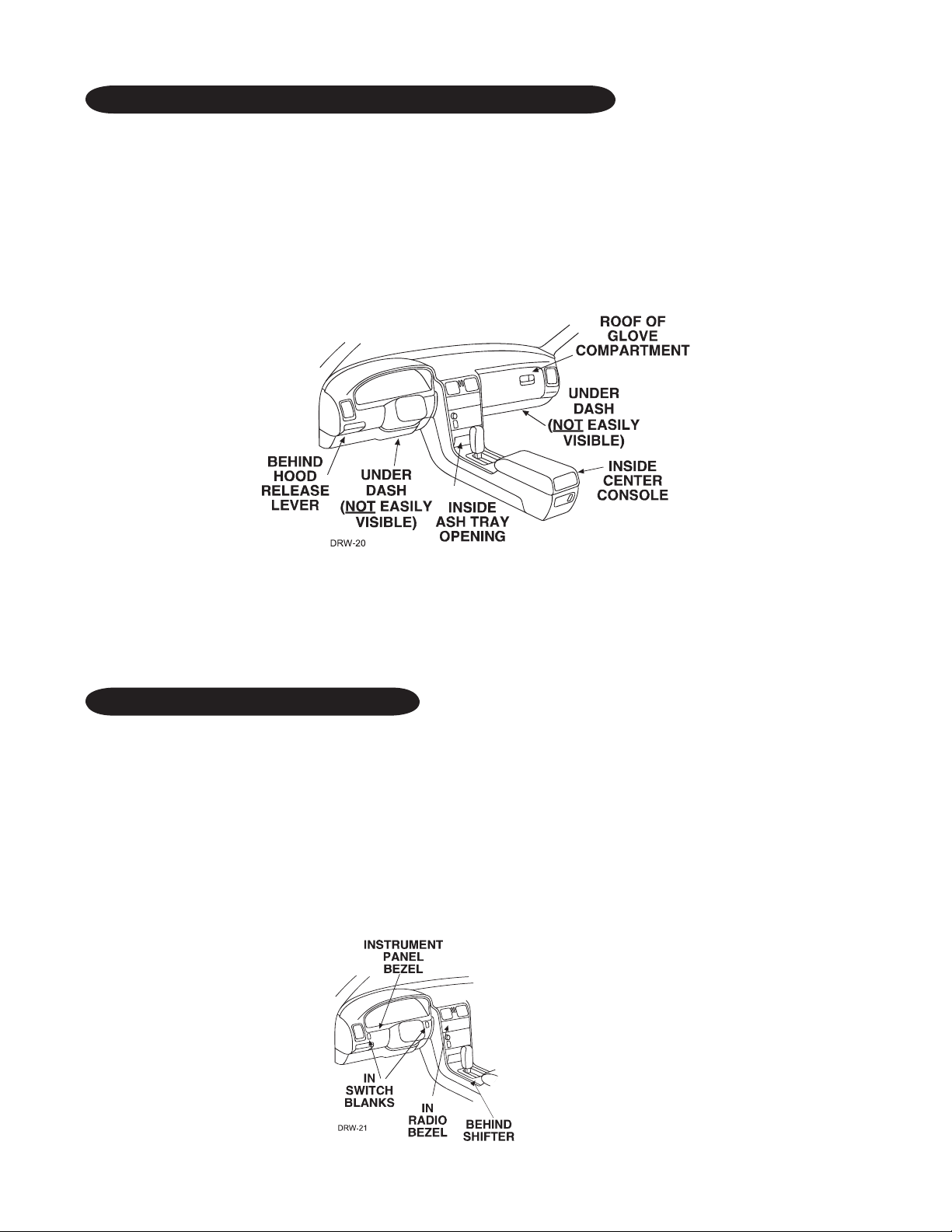
locations for the control module
Some things to remember about where to mount the control module:
■ Never put the control module in the engine compartment!
■ The first step in hot-wiring a vehicle is removing the driver's side under-dash panel to access the starter
and ignition wires. If the control module is placed just behind the driver's side dash it can easily be discon-
nected.
■ When mounting the control module, try to find a secure location that will not require you to extend the har-
nesses’ wires (they are 1.5 meters long). Keep it away from the heater core (or any other heat sources) and
any obvious leaks.
■ Some good control module locations are: Above the glove box, inside the center console, above the under-
© 2005 Directed Electronics—all rights reserved 7

DRAFT
dash fuse box, or above the radio.
DRAFT
mounting the antenna
The antenna position should be discussed with the vehicle’s owner prior to installation, since the antenna may
be visible to the vehicle’s operator. The best location for the antenna is centered high on either the front or
rear windshield. For optimal range, the antenna should be mounted horizontally. It can be mounted vertically
but range will be diminished. Metallic window tint can also affect range, so this should be a consideration when
determining the mounting location.
After determining the best mounting location, follow these steps:
1. Clean the mounting area with a quality glass cleaner or alcohol to remove any dirt or residue.
3. Mount the antenna using the supplied double-sided tape.
4. Route the antenna cable to the control module and plug it into the antenna connector.
IMPORTANT! To achieve the best possible range, DO NOT leave the antenna cable bundled under the
dash. Always extend the cable full length during installation, regardless of the antenna mounting
location.
locations for stinger doubleguard shock sensor
Some things to remember about where to mount the shock sensor:
■ Never put the Stinger® in the engine compartment!
■ Find a spot close to the control module so that the wires do not need to be extended. Keep it away from the
heater core (or any other heat sources) and any obvious leaks.
How the Stinger® is mounted is the most important factor in its performance. We recommend two meth-
ods:
■ Using double-sided tape or hook-and-loop fastener to mount to a trim panel or an air duct,
or
■ Wire-tying to a wire harness.
If mounting the sensor where it cannot be easily reached for adjustment, hook-and-loop fastening tape (such as
Velcro) is recommended for ease of removal for future adjustments.
NOTE: In many vehicles, tying the sensor to a steering column or screwing it to metal will result in
poor sensitivity, especially at the rear of the vehicle.
8 © 2005 Directed Electronics—all rights reserved
DRAFT
locations for valet/program switch
DRAFT
IMPORTANT! When the vehicle is delivered, please show the user where this switch is lo cat ed and
how to disarm the system with it.
Ensure that the location you pick for the switch has sufficient clearance to the rear. The switch should be well
hidden. It should be placed so pas sen gers or stored items (such as in a glove box or center console) cannot
accidentally hit it. The switch fits into a
9
/32-inch hole.
This system has Remote Valet. The user can enter and exit Valet Mode without having to reach the Valet/Program
switch. This feature was introduced so that switch location was less critical in day-to-day use. As long as the
Valet/Program switch can be reached to disarm without a transmitter, easy access is not important.
locations for the status LED
Things to remember when po si tion ing the Status LED:
■ It should be visible from both sides and the rear of the vehicle, if possible.
■ It needs at least
■ It is easiest to remove a small panel, such as a switch blank or a dash bezel, before drilling a
hole.
■ Use quick-disconnects near the LED wires if the panel is re mov able. This lets me chan ics or other installers
remove the pan el with out cut ting the wires.
1
/2-inch clearance to the rear.
9
/32-inch
© 2005 Directed Electronics—all rights reserved 9
DRAFT
locations for the optional starter kill relay
DRAFT
If optional starter kill relay or its connections are immediately visible upon removal of the under-dash panel, they
can easily be bypassed. Always make the relay and its con nec tions difficult to discern from the factory wiring!
Exposed yellow butt connectors do not look like factory parts, and will not fool anyone! For this reason, routing
the optional starter kill wires away from the steering column is recommended.
locations for the relay satellite
The relay satellite wiring carries large amounts of current. The wires should not be extended and should be cut
to the minimum length necessary. Since the relay satellite is functioning as the ignition switch in the vehicle, it
is often convenient to mount the relay satellite close to the main ignition switch harness.
finding the wires you need
Now that you have decided where each component will be located, you’re going to find the wires in the car that
the security system will be connected to.
IMPORTANT! Do not use a 12V test light or logic probe (computer safe test light) to find these
wires! Use a digital multimeter for all testing.
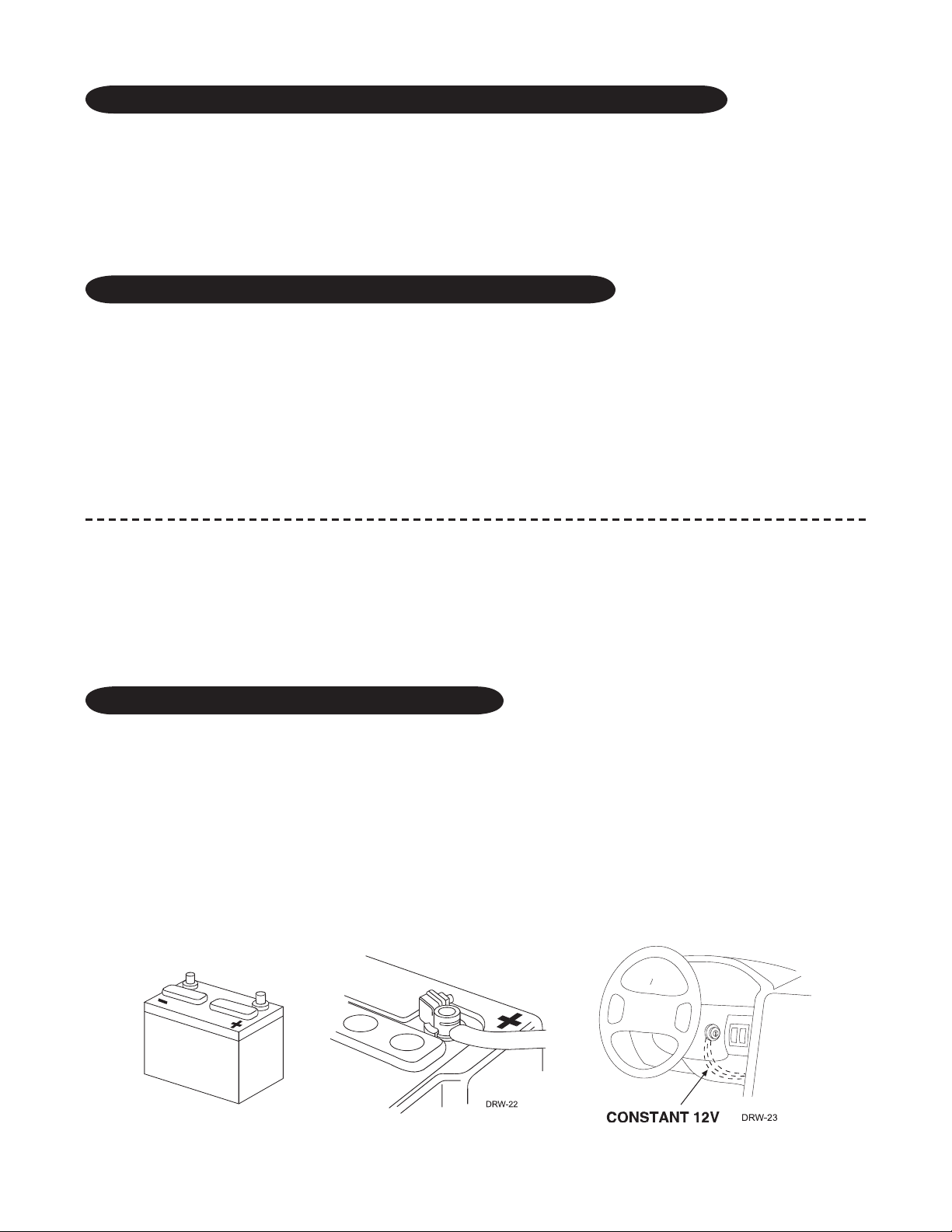
obtaining constant 12V
We recommend two possible sources for 12V constant: the (+) terminal of the battery, or the constant supply to
the ignition switch. Always install a fuse within 12 inches of this connection. If the fuse also will be powering
other circuits such as door locks, fuse accordingly.
IMPORTANT! Do not remove the fuse holder on the red wire. It ensures that the control module
has its own fuse, of the proper value, regardless of how many accessories are added to the main power
feed.
10 © 2005 Directed Electronics—all rights reserved
DRAFT
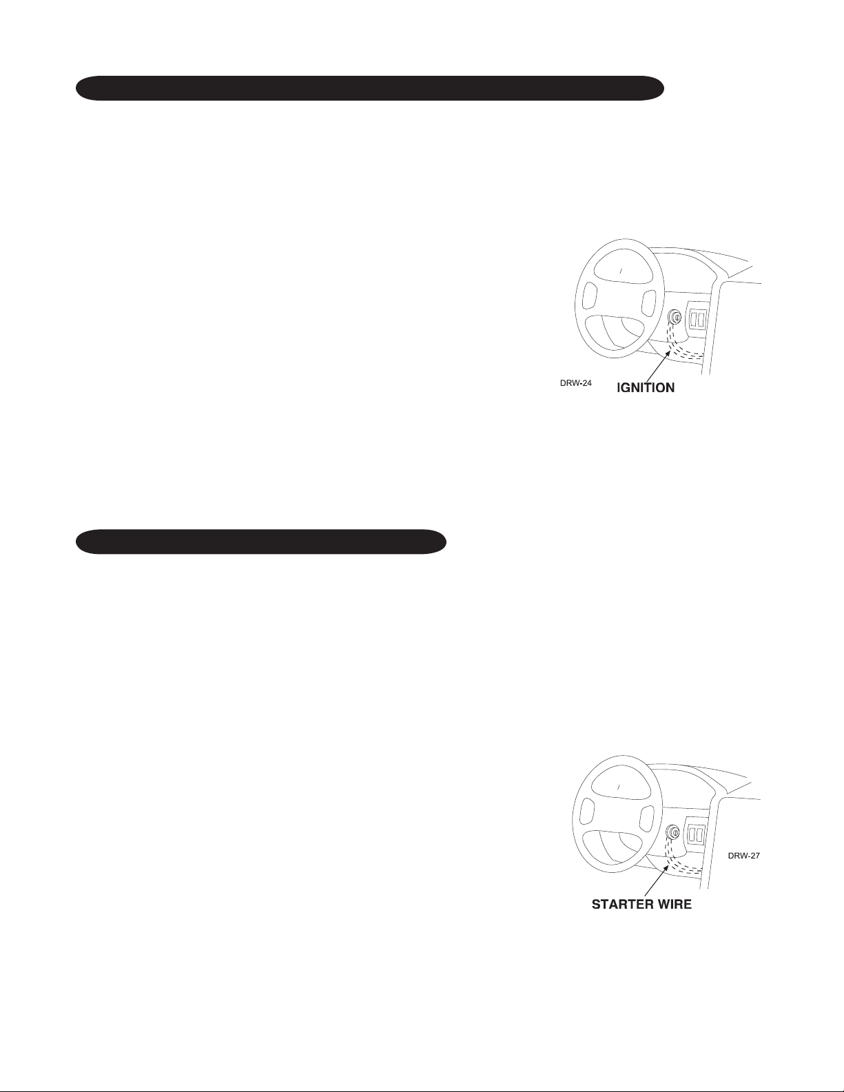
finding the 12V switched ignition wire
DRAFT
The ignition wire is powered when the key is in the run or start position. This is because the ignition wire powers
the ignition system (spark plugs, coil) as well as the fuel delivery system (fuel pump, fuel injection computer).
Accessory wires lose power when the key is in the start position to make more current avail able to the starter
motor.
How to find (+)12V ignition with your multimeter:
1. Set to DCV or DC voltage (12V or 20V is fine).
2. Attach the (-) probe of the meter to chassis ground.
3. Probe the wire you suspect of being the ignition wire. The steering
column harness or ig ni tion switch harness is an excellent place to find
this wire.
4. Turn the ignition key switch to the run position. If your meter reads (+)12V,
go to the next step. If it doesn’t, probe another wire.
5. Now turn the key to the start po si tion. The meter display should stay
steady, not drop ping by more than a few tenths of a volt. If it drops close to or all the way to zero, go back
to Step 3. If it stays steady at (+)12V, you have found an ig ni tion wire.
finding the starter wire
The starter wire provides 12V directly to the starter or to a relay controlling the starter. In some vehicles, it is
necessary to power a cold start circuit. A cold start circuit will test exactly like a starter circuit, but it does not
control the starter. Instead, the cold start circuit is used to prime the fuel injection system for starting when
the vehicle is cold.
How to find the starter wire with your multimeter:
1. Set to DCV or DC voltage (12V or 20V is fine).
2. Attach the (-) probe of the meter to chassis ground.
3. Probe the wire you suspect of being the starter wire. The steering
column is an ex cel lent place to find this wire. Re mem ber you do not
need to interrupt the starter at the same point you test it. Hiding your
optional starter kill relay and con nec tions is always rec om mend ed.
4. Turn the ignition key switch to the start position. Make sure the car
is not in gear! If your meter reads (+)12V, go to the next step. If it
doesn’t, probe another wire.
5. Cut the wire you suspect of being the starter wire.
6. Attempt to start the car. If the starter engages, reconnect it and go back to Step 3. If the starter does not
© 2005 Directed Electronics—all rights reserved 11

DRAFT
turn over, you have the right wire.
DRAFT
finding the accessory wire
An accessory wire will show +12V when the key is in the accessory and run positions. It will not show +12V
during the cranking cycle. There will often be more than one accessory wire in the ignition harness. The correct
accessory wire will power the vehicle's climate control system. Some vehicles may have separate wires for the blower
motor and the air conditioning compressor. In such cases, it will be necessary to add a relay to power the second
accessory wire.
finding the tachometer wire
To test for a tachometer wire, a multimeter capable of testing AC voltage must be used. The tachometer wire will
show between 1V and 6V AC. In multi-coil ignition systems, the system can learn individual coil wires. Individual
coil wires in a multi-coil ignition system will register lower amounts of AC voltage. Also, if necessary, the system
can use a fuel injector control wire for engine speed sensing. Common locations for a tachometer wire are the
ignition coil itself, the back of the gauges, engine computers, and automatic transmission computers.
IMPORTANT! Do not test tachometer wires using a test light or logic probe (computer safe test light)!
This will damage the vehicle.
How to find a tachometer wire with your multimeter:
1. Set to ACV or AC voltage (12V or 20V is fine).
2. Attach the (-) probe of the meter to chassis ground.
3. Start and run the vehicle.
4. Probe the wire you suspect of being the tachometer wire with the red probe of the meter.
5. If this is the correct wire the meter will read between 1V and 6V.
finding the wait-to-start bulb wire for diesels
In diesel vehicles it is necessary to interface with the wire that turns on the WAIT TO START light in the dash-
board. This wire illuminates the bulb until the vehicle’s glow plugs are properly heated. When the light goes out
the vehicle can be started. This wire is always available at the connector leading to the bulb in the dashboard.
It can also be found at the Engine Control Module (ECM) in many vehicles.
To test and determine the polarity of this wire:
1. Set your multimeter to DCV or DC voltage (12 or 20V is fine).
2. Attach the (+) probe of the meter to (+)12V.
3. Probe the wire that you suspect leads to the bulb with the (-) probe of the meter.
4. Turn the ignition switch to the ON position.
5. If the meter indicates 12 volts until the light goes out you have isolated the correct wire and the wire's
12 © 2005 Directed Electronics—all rights reserved
DRAFT
polarity is negative (ground while the bulb is on).
DRAFT
6. If the meter reads zero volts until the light goes out and then reads 12 volts, you have isolated the correct
wire and the wire's polarity is positive.
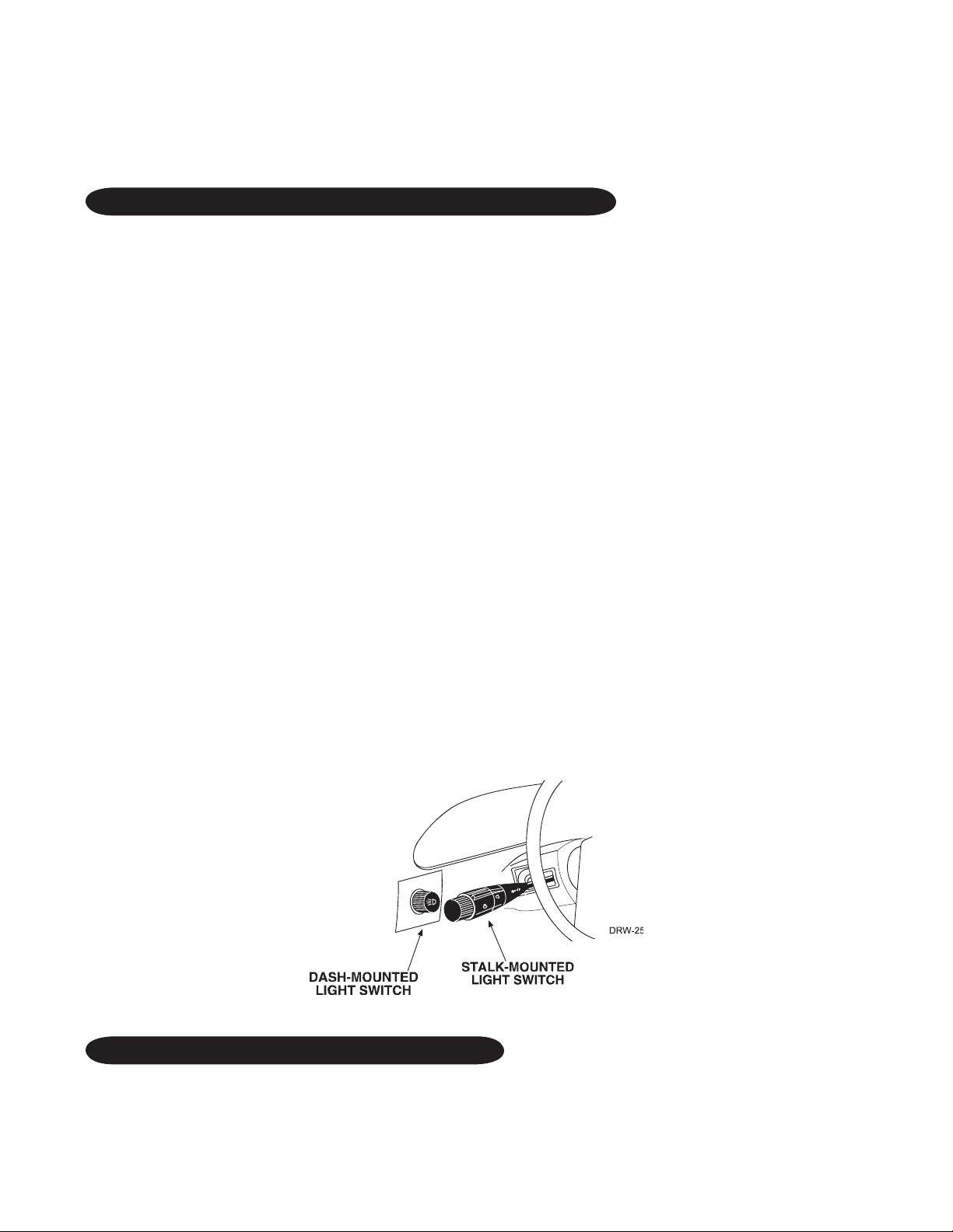
finding a (+) parking light wire
The (+) parking light wire is often found near the switch. Many cars have the switch built into the turn signal
lever, and in these cars the parking light wire can be found in the steering column. The same wire is often avail-
able in the kick panel or running board.
NOTE: Many Toyotas, as well as many other Asian vehicles, send a (-) signal from the switch to a
relay. The relay then sends (+)12V to the bulbs. Whenever you have difficulty finding a (+) parking
light wire near the switch, simply test the wires at any switch or control panel which is lit by the
instrument panel lighting. Remember, you need a (+) parking light wire that does not vary with
the dimmer setting.
How to find a (+) parking light flash wire with your multimeter:
1. Set to DCV or DC voltage (12V or 20V is fine).
2. Attach the (-) probe of the meter to chassis ground.
3. Probe the wire you suspect of being the parking light wire. Usually, the area near the headlight/park ing light
switch is an excellent area to start, as is the kick panel.
4. Turn on the parking lights. If your meter shows (+)12V, turn off the parking lights and make sure it goes back
to zero.
5. If it does return to zero, turn the parking lights back on and, using the dash light dim mer con trol, turn the
brightness of the dash lights up and down. If the meter changes more than a volt when using the dimmer,
look for an oth er wire. If it stays relatively close to (+)12V, you have found your parking light wire.
finding the door pin switch circuit
The best places to find the door switch wire are:
■ At the pin switch: When testing at the pin switch, check the wire to ensure that it “sees” all the doors. Often,
the passenger switch will cover all the doors even if the driver’s switch will not.
© 2005 Directed Electronics—all rights reserved 13

DRAFT
■ At the dome light: This may not be your best choice if the vehicle has delayed domelight supervision, but it
DRAFT
will work in many Hondas, or any vehicle with completely diode-isolated pin switches.
Once you have determined the wire color, the easiest place to connect to the wire is often at the kick panel,
at the windshield pillar, or in the running board. When an easy location is not available, running a wire to the
domelight itself is often the best solution.
How to find a door pin switch trigger wire with your multimeter:
1. Set to DCV or DC voltage (12V or 20V is fine).
2. In most Fords, fasten the (-) probe of the meter to chassis ground. In most other cars, fasten the (+) probe
of your meter to (+)12V con stant.
3. Probe the wire you suspect of being the door trigger wire. If the meter reads (+)12V when any door
is opened, you have found a trigger wire.
NOTE: Make sure the wire you use “sees” all the doors! Some newer GM vehicles lack standardtype pin switches. The dome light in these vehicles is turned on when the door handle is lifted.
These usually have a blue/white or white wire coming out of the door into the kick panel which
will provide a (-) trigger for all doors. Some GM vehicles (some Cavaliers, Grand Ams, etc.) have a
yellow wire coming out of the door which provides a (+) door trigger.
making your wiring connections
Before making your connections, plan how your wires will be routed through the vehicle. For instance, the red
12V constant input and the orange ground-when-armed output (for the optional starter kill relay) will often be
routed together to the ignition switch harness. In order to keep the wiring neat and make it harder to find, you
may wish to wrap these wires together in electrical tape or conceal them in tubing similar to what the manu-
facturer used.
There are two acceptable ways of making a wire connection - solder con nec tions and crimp connectors. When
properly performed, either type of connection is reliable and trouble-free. Regardless of whether you solder your
connections or you use mechanical-type crimp-on connections, ensure that all connections are mechanically
sound and that they are insulated.
Cheap electrical tape, especially when poorly applied, is not a reliable insulator. It often falls off in hot weather.
Use good-quality electrical tape or heat shrink.
■ Never twist-and-tape the wires together without soldering.
■ Never use “fuse taps”, as they can damage fuse box terminals.
If you use tapping connectors such as 3M T-Taps (not to be confused with Scotch-Locks), avoid using them in
higher-current applications (constant 12V, ground, etc.). Some tapping connectors are inferior in quality and
14 © 2005 Directed Electronics—all rights reserved
DRAFT
should be avoided.
DRAFT
primary harness (H1), 12-pin connector
H1/1
______
______
______
______
______
______
______
______
______
______
______
H1/2
H1/3
H1/4
H1/5
H1/6
H1/7
H1/8
H1/9
H1/10
H1/11
H1/12
______
RED/WHITE (-) 200 mA CHANNEL 2 VALIDITY OUTPUT
RED (+) CONSTANT POWER INPUT
BROWN (+) SIREN OUTPUT
EMPTY NOT USED
BLACK (-) CHASSIS GROUND INPUT
VIOLET (+) DOOR TRIGGER INPUT, ZONE 3
BLUE (-) MULTIPLEXED INPUT, ZONE 4
GREEN (-) DOOR TRIGGER INPUT, ZONE 3
BLACK/WHITE (-) 200 mA DOMELIGHT SUPERVISION OUTPUT
WHITE/BLUE (-) REMOTE START ACTIVATION INPUT
WHITE (+)/(-) SELECTABLE LIGHT FLASH OUTPUT
ORANGE (-) 500 mA ARMED OUTPUT
auxiliary harness (H2), 6-pin connector
H2/1
______
______
______
______
______
© 2005 Directed Electronics—all rights reserved 15
H2/2
H2/3
H2/4
H2/5
H2/6
______
LIGHT BLUE (-) SECOND UNLOCK OUTPUT
WHITE/BLACK (-) CHANNEL 5 OUTPUT
VIOLET/BLACK (-) CHANNEL 4 OUTPUT
GREEN/WHITE (-) FACTORY ALARM REARM
GRAY/BLACK (-) WAIT TO START INPUT
LIGHT GREEN/BLACK (-) FACTORY ALARM DISARM
DRAFT
door lock harness, 3-pin connector
DRAFT
1
______
______
______
2
3
Note: Refer to TechTip 1041 for wiring information.
LIGHT BLUE (+) LOCK (-) UNLOCK OUTPUT
EMPTY NOT USED
GREEN (-) LOCK (+) UNLOCK OUTPUT
remote start ribbon harness, wiring diagram
1
______
2
______
3
______
4
______
5
______
PINK/WHITE 200 mA (-) PROGRAMMABLE IGN2/ACC2 RELAY TURN ON
YELLOW (+) IGNITION INPUT TO ALARM
PINK (-) 200 mA IGNITION RELAY TURN-ON
ORANGE (-) 200 mA ACCESSORY RELAY TURN-ON
PURPLE (-) 200 mA STARTER RELAY TURN-ON
______
______
This ribbon harness connects to the relay satellite.
16 © 2005 Directed Electronics—all rights reserved
6
7
ORANGE/BLACK (-) ANTIGRIND/GROUND WHEN ARMED OUTPUT
BLUE (-) 200 mA STATUS OUTPUT
DRAFT
heavy gauge inline connector
DRAFT
key switch interface
1
______
______
______
______
______
______
______
______
2
3
4
5
6
7
8
PURPLE (+) STARTER OUTPUT TO STARTER (STARTER SIDE)
GREEN STARTER INPUT FROM IGNITION (KEY SIDE)
RED (+) HIGH CURRENT 12V INPUT
ORANGE (+) OUTPUT TO ACCESSORY CIRCUIT
PINK (+) OUTPUT TO PRIMARY IGNITION CIRCUIT
RED (+) (30A) HIGH CURRENT 12V INPUT
PINK/WHITE (+) OUTPUT TO SECOND IGNITION CIRCUIT
RED/WHITE (+) (30A) HIGH CURRENT 12V INPUT
remote start harness (H3), 5-pin connector
H3/1
______
______
______
______
H3/2
H3/3
H3/4
H3/5
______
BLACK/WHITE (-) NEUTRAL SAFETY SWITCH INPUT
VIOLET/WHITE TACHOMETER INPUT WIRE
BROWN (+) BRAKE SHUTDOWN WIRE
GRAY (-) HOOD PINSWITCH INPUT, ZONE 1
BLUE/WHITE (-) 200 mA 2ND STATUS/REAR DEFOGGER- LATCHED/PULSED
horn, channel 6 (H4), 2-pin connector
H4/1
______
H4/2
______
ORANGE/BLACK CHANNEL 6 OUTPUT
BROWN (-) 200mA HORN
© 2005 Directed Electronics—all rights reserved 17
DRAFT
primary harness (H1) wire connection guide
DRAFT
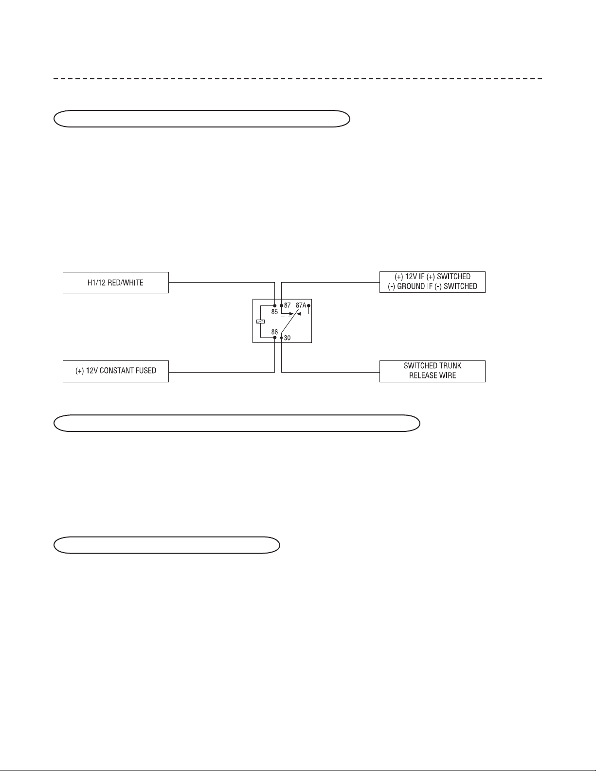
H1/1 RED/WHITE channel 2, 200mA (-) output
When the system receives the code controlling Channel 2, for longer than 1.5 seconds, the red/white wire will
supply an output as long as the transmission continues. This is often used to operate a trunk/hatch release or
other relay-driven function.
IMPORTANT! Never use this wire to drive anything but a relay or a low-current input! The transistorized output can only supply 200 mA of current. Connecting directly to a solenoid, motor, or other
high-current device will cause it to fail.
H1/2 RED (+)12V constant power input
Before connecting this wire, remove the supplied fuse. Connect to the battery positive terminal or the constant
12V supply to the ignition switch.
NOTE: Always use a fuse within 12 inches of the point you obtain (+)12V. Do not use the 15A fuse
in the harness for this purpose. This fuse protects the module itself.
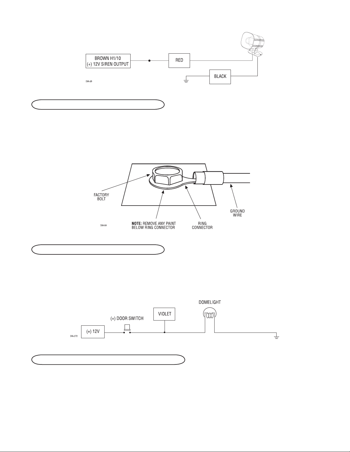
H1/3 BROWN (+) siren output
Connect this to the red wire of the siren. Connect the black wire of the siren to (-) chassis ground, preferably at
the same point you connected the control module’s black ground wire. See Features Description section for horn
output.
18 © 2005 Directed Electronics—all rights reserved
DRAFT
H1/5 BLACK (-) chassis ground connection
DRAFT
Remove any paint and connect this wire to bare metal, preferably with a factory bolt rather than your own screw.
(Screws tend to either strip or loosen with time.) We recommend grounding all your components, including the
siren, to the same point in the vehicle.
H1/6 VIOLET (+) door trigger input, zone 3
This wire is used in vehicles that have a positive (+) switched dome light circuit. Connect the violet wire to a wire
that shows (+)12V when any door is opened, and ground when the door is closed. This wire will report Zone 3.
H1/7 BLUE (-) multiplex input, zone 4
Inputs shorter than 0.8 seconds will trigger the Warn Away response, while inputs longer than 0.8 seconds will
trigger the full alarm sequence. If installing an optional Directed Electronics dual stage sensor, connect both the
blue and the green wires of the optional sensor to this input. This wire will report Zone 4.
© 2005 Directed Electronics—all rights reserved 19
DRAFT
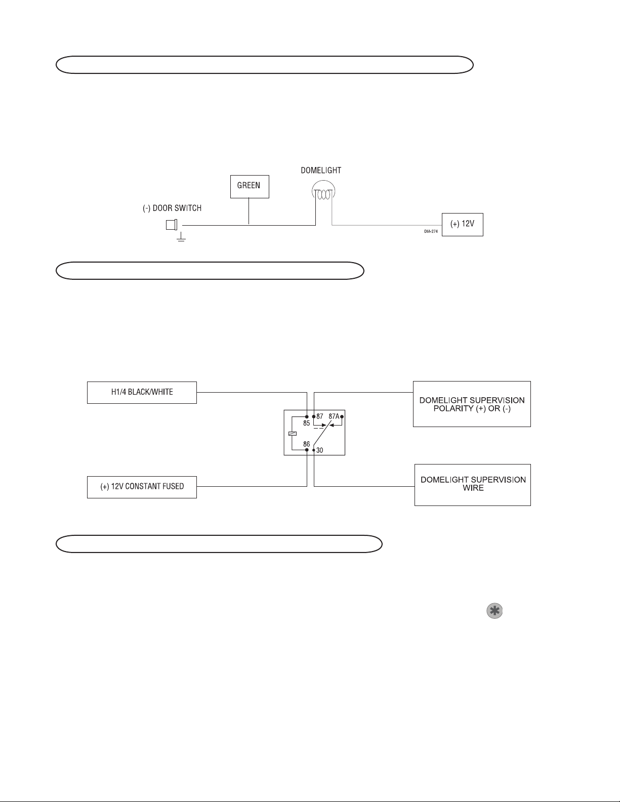
H1/8 GREEN (-) door trigger input, zone 3
DRAFT
Most vehicles use negative door trigger circuits. Connect the green wire to a wire which shows ground when any
door is opened. In vehicles with factory delays on the domelight circuit, there is usually a wire that is unaffected
by the delay circuitry. This wire will report Zone 3.
H1/9 BLACK/WHITE (-) 200 mA domelight supervision output
Connect this wire to the optional domelight supervision relay as shown below:
IMPORTANT! This output is only intended to drive a relay. It cannot be connected directly to the
domelight circuit, as the output cannot support the current draw of one or more light bulbs.
H1/10 WHITE/BLUE remote start (-) activation input
This input comes from the factory set to 2 activation pulses. This means that it is necessary to have 2 consecu-
tive ground pulses on the white/blue wire for the remote start to activate or to deactivate. The same holds true
for the remote control activation when set to a two pulse setting it is necessary to press the
for the remote start to activate or deactivate.
NOTE: The number of activation inputs can be programmed to 1 or 2 pulses. This setting affects
both the input wire and the remote control when operating the remote starter.
20 © 2005 Directed Electronics—all rights reserved
button twice
 Loading...