

Page 1

using XDi-N indicators
APPLICATION NOTES
Document no.: 4189350080C
WIND MEASURING SYSTEMS
Page 2

Wind Measuring Systems Application notes, using XDi-N indicators
Table of contents
GENERAL INFORMATION .......................................................................................................... 4
WARNINGS, LEGAL INFORMATION AND SAFETY ............................................................................... 4
LEGAL INFORMATION AND DISCLAIMER ........................................................................................... 4
DISCLAIMER ................................................................................................................................. 4
SAFETY ISSUES ............................................................................................................................ 4
ELECTROSTATIC DISCHARGE AWARENESS ..................................................................................... 4
FACTORY SETTINGS ..................................................................................................................... 4
ABOUT THE APPLICATION NOTES........................................................................................... 5
GENERAL PURPOSE ...................................................................................................................... 5
INTENDED USERS ......................................................................................................................... 5
CONTENTS/OVERALL STRUCTURE .................................................................................................. 5
DATA SHEETS AND OTHER DOCUMENTS .............................................................................. 6
PRODUCT INSTALLATION DETAILS ......................................................................................... 7
XDI-N CONNECTIONS ................................................................................................................... 7
XDI-N CONNECTIONS ON MAIN UNIT .............................................................................................. 8
NX2 NMEA EXTENSION MODULE CONNECTIONS ............................................................................ 8
WSS 750 WIND SENSOR CABLE CONNECTIONS ............................................................................. 9
WIND SYSTEM ACCESSORIES ...................................................................................................... 10
OTHER MANUFACTURER’S WIND SENSORS ................................................................................... 10
SYSTEM APPLICATIONS .......................................................................................................... 11
SYSTEM 1 - RELATIVE WIND INDICATOR SYSTEM .......................................................................... 11
SYSTEM 2 - DUAL RELATIVE WIND INDICATION .............................................................................. 13
SYSTEM 3 - RELATIVE AND TRUE WIND INDICATION ....................................................................... 16
SYSTEM 4 - RELATIVE, TRUE AND GEOGRAPHIC TRUE WIND INDICATION ......................................... 19
SYSTEM 5 - DUAL RELATIVE, TRUE AND GEOGRAPHICAL WIND INDICATION ...................................... 22
SYSTEM 6 - WIND SYSTEM FOR BI-DIRECTIONAL FERRY (RO-RO) .................................................. 26
OUTPUT NMEA TO OTHER SYSTEMS .................................................................................... 31
CONFIGURE THE NMEA OUTPUT PORT ........................................................................................ 31
APPENDIX 1 - XDI-N SETUP WIZARD AND NMEA SETUP .................................................... 33
XDI-N SETUP DURING INSTALLATION ........................................................................................... 33
CHANGE NMEA SETUP .............................................................................................................. 41
ADJUST WIND DIRECTION INPUT TO CORRECT SENSOR MISALIGNMENT ........................................... 43
CHANGING FILTER SETTINGS ....................................................................................................... 44
THE OTHER INPUT CONFIGURATION PARAMETERS ........................................................................ 45
EDIT THE INDICATOR HEADLINE ................................................................................................... 45
APPENDIX 2 – NORMAL OPERATION OF XDI-N .................................................................... 47
TOGGLE BETWEEN SCREENS ....................................................................................................... 47
DIMMER UP/DOWN ...................................................................................................................... 47
CHANGE THE WIND SPEED UNIT ................................................................................................... 48
QUICK MENU .............................................................................................................................. 49
APPENDIX 3 - TROUBLESHOOTING ....................................................................................... 50
NMEA MONITOR ........................................................................................................................ 50
APPENDIX 4 - EXTERNAL DIMMING ....................................................................................... 52
DIMMER OPTIONS ....................................................................................................................... 52
DIMMING FROM EXTERNAL PUSH-BUTTONS .................................................................................. 52
DIMMING FROM EXTERNAL POTENTIOMETER (AX1) ...................................................................... 52
DEIF A/S Page 2 of 69
Page 3

Wind Measuring Systems Application notes, using XDi-N indicators
DIMMING FROM ANALOGUE VOLTAGE INPUT (AX1) ....................................................................... 53
DIMMING FROM A CENTRAL SYSTEM USING NMEA ....................................................................... 53
APPENDIX 5 - INSTALLING A CAN BUS SYSTEM ................................................................. 54
XDI-N CAN BUS PORTS ............................................................................................................. 54
CAN BUS SYSTEM WIRING .......................................................................................................... 54
CAN BACKBONE AND TERMINATION ............................................................................................. 54
SHIELDING AND GROUNDING OF THE CAN BUS CABLES ................................................................ 55
APPENDIX 6 - REPLACING WSDI-2 WITH XDI-N .................................................................... 57
WSDI-2 .................................................................................................................................... 57
SETUP XDI-N TO REPLACE A WSDI-2 PRESENTING RELATIVE AND TRUE WIND .............................. 59
XDI-N SHOWING RELATIVE WIND ................................................................................................. 59
XDI-N SHOWING TRUE WIND ....................................................................................................... 59
EXTEND YOUR SYSTEM WITH GEOGRAPHIC TRUE WIND ................................................................. 59
APPENDIX 7 – DEFINITION OF RELATIVE AND TRUE WIND ............................................... 60
RELATIVE WIND .......................................................................................................................... 60
TRUE WIND ................................................................................................................................ 60
GEOGRAPHIC TRUE WIND ............................................................................................................ 60
CALCULATING TRUE WIND ........................................................................................................... 61
GEOGRAPHIC WIND .................................................................................................................... 61
APPENDIX 8 – STANDARD WIND LIBRARY OVERVIEW ...................................................... 62
APPENDIX 9 – ORDERING A WIND SYSTEM ......................................................................... 66
ORDER SHEET SYSTEM 1, 3 OR 4 – SINGLE INDICATOR SYSTEM ............................................. 66
ORDER SHEET SYSTEM 2, 5 - DOUBLE INDICATOR SYSTEM .................................................... 67
ORDER SHEET SYSTEM 6 - DOUBLE INDICATOR SYSTEM FOR RO-RO FERRIES ...................... 68
ACCESSORIES ............................................................................................................................ 69
DEIF A/S Page 3 of 69
Page 4
Wind Measuring Systems Application notes, using XDi-N indicators
The units are not to be opened by unauthorised personnel. If opened anyway, the
The notes provide general information which will be helpful for the reader to bear
General information
Warnings, legal information and safety
Warnings and notes
Throughout this document, a number of notes with helpful user information will be presented. To
ensure that these are noticed, they will be highlighted as follows in order to separate them from
the general text.
Notes
Legal information and disclaimer
DEIF takes no responsibility for installation or operation of the product. If there is any doubt about
how to install or operate the product, the company responsible for the installation or the operation
must be contacted.
in mind.
warranty will be lost.
Disclaimer
DEIF A/S reserves the right to change any of the contents of this document without prior notice.
The English version of this document always contains the most recent and up-to-date
information about the product. DEIF does not take responsibility for the accuracy of translations,
and translations might not be updated at the same time as the English document. If there is a
discrepancy, the English version prevails.
Safety issues Installing and operating the product may imply work with dangerous currents and voltages.
Therefore, the installation should only be carried out by authorised personnel who understand the
risks involved in working with live electrical equipment.
Electrostatic discharge awareness
Sufficient care must be taken to protect the terminals against static discharges during the
installation. Once the unit is installed and connected, these precautions are no longer necessary.
Factory settings The product is delivered from factory with certain factory settings. These are based on average
values and are not necessarily the correct settings for matching the product in question.
Precautions must be taken to check the settings before running the product.
DEIF A/S Page 4 of 69
Page 5

Wind Measuring Systems Application notes, using XDi-N indicators
About the application notes
General purpose
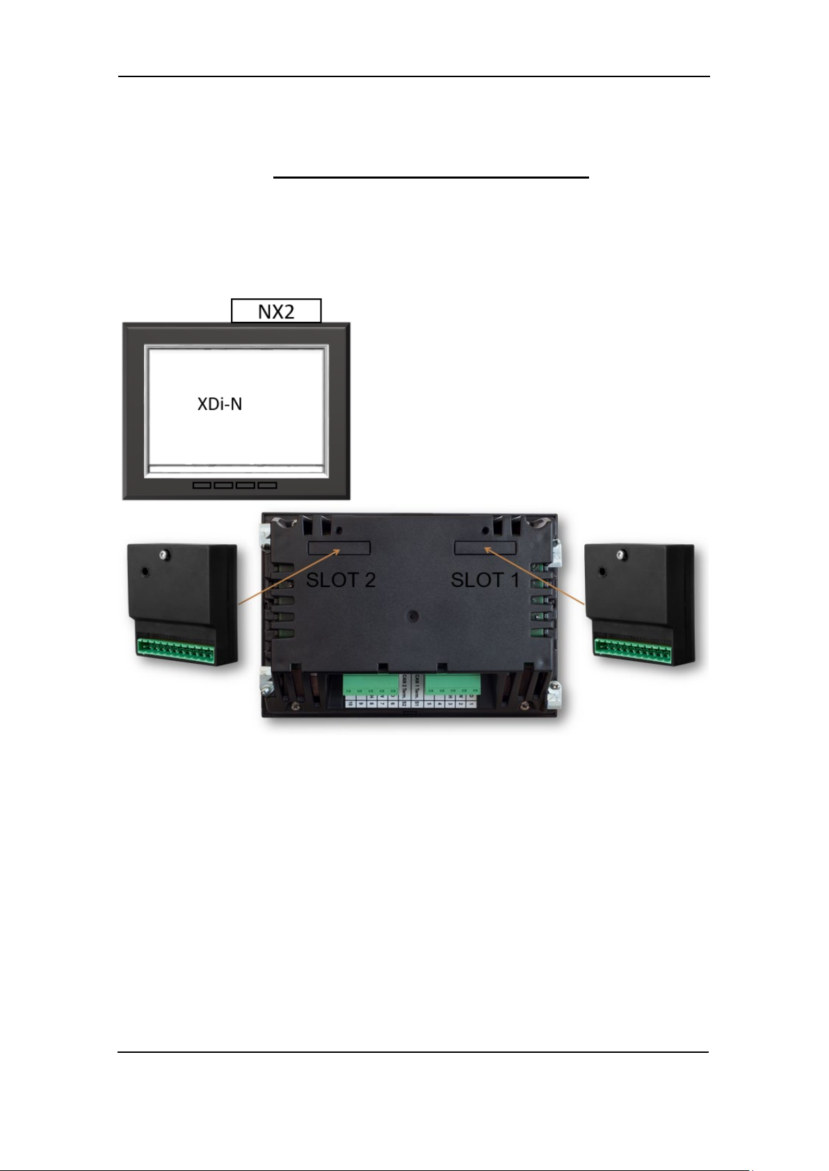
This document includes application notes for DEIF’s wind sensors type WSS 550 and WSS 750
in system solution with one or more XDi-N display-based wind indicators.
XDi-N is available in three sizes: XDi 96 N, XDi 144 N and XDi 192 N.
The DEIF XDi-N Wind version is delivered with a pre-installed indicator library with a selection of
standard wind indicators to choose from during installation.
The setup guidance in this application note refers to the DEIF standard wind indicator library:
Library owner: 000002 Library no. 001 for XDi 144 N and XDi 192 N.
A similar library is available for XDi 96 N with the same owner and library number.
In this document, you can find typical application examples for different types of vessels.
In the application examples, the DEIF standard heated wind sensor WSS 550 is used.
For demanding applications, the WSS 550 can be directly replaced by the DEIF high performance
WSS 750 sensor.
It is also possible to use another manufacturer’s wind sensor providing a standard NMEA wind
data output.
The general purpose of the application notes is to provide the necessary design information about
typical wind measuring systems.
Intended users
The document is mainly intended for the person responsible for the technical designing of wind
indicator systems for ships. In most cases, this would be a system integrator or bridge panel
designer. Naturally, other users might also find useful information in this document.
It is important to read the user and installation documentation in addition to the information you get
in this application note.
Contents/overall structure
The document is divided into chapters and in order to make the structure of the document simple
and easy to use, each chapter will begin from the top of a new page.
DEIF A/S Page 5 of 69
Page 6

Wind Measuring Systems Application notes, using XDi-N indicators
Data sheets and other documents
From the DEIF website www.deif.com
manuals, type approval certificates and additional application notes are available for download,
this document included.
In the below listed documents, further information about the components in the DEIF wind
indication system can be found:
- XDi data sheet 4921250067 UK
- XDi-Standard virtual indicator library 4189350067 UK
- XDi designer’s handbook 4189350049 UK
- XDi-net CANopen reference manual 4189350066 UK
- WSS 500 series data sheet 4921250078 UK
- WSS 500 series user’s manual and installation note 4189350072 UK
- WSS 700 series data sheet 4921250070 UK
- WSS 750 User manual and installation note 4189350059 UK
, additional documentation such as data sheets, installation
DEIF A/S Page 6 of 69
Page 7
Wind Measuring Systems Application notes, using XDi-N indicators
Product installation details
XDi-N connections
In the following, the term XDi-N represents any of the three sizes: XDi 96 N, XDi 144 N or XDi
192 N.
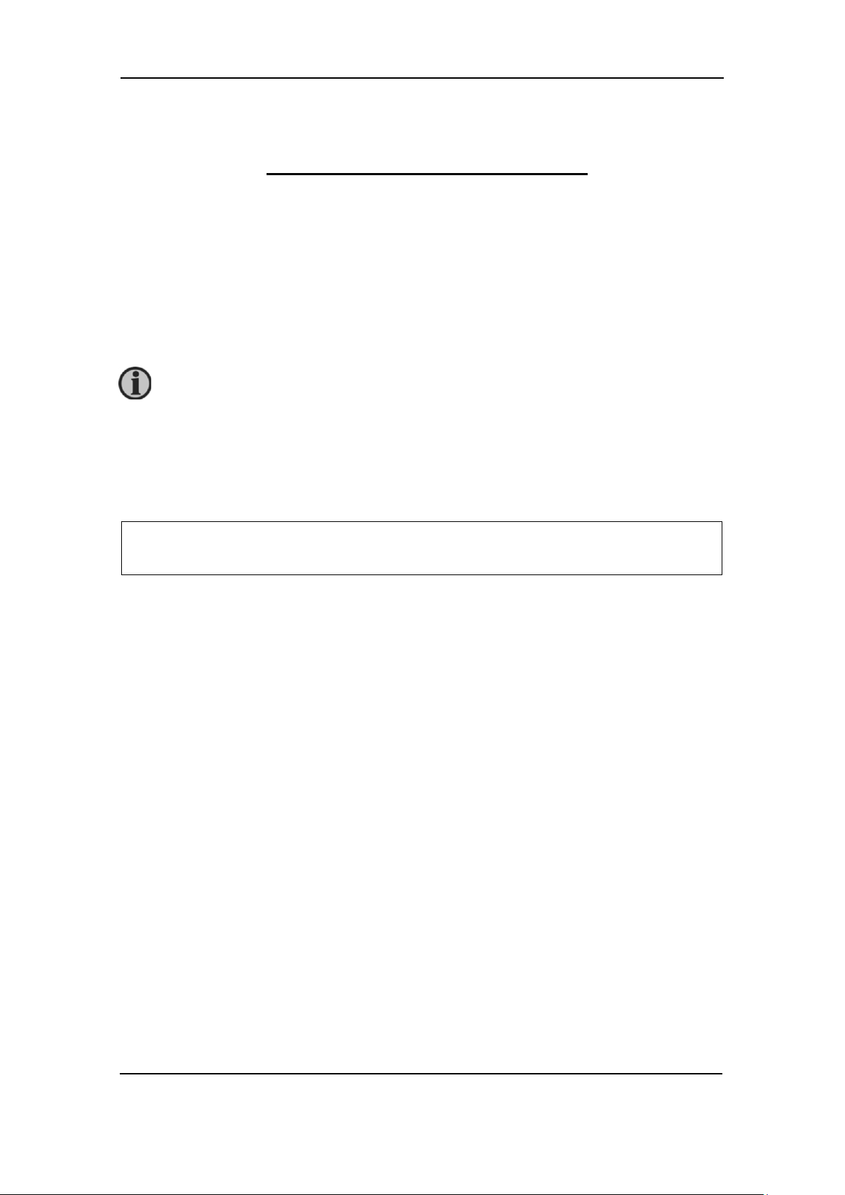
To present wind data from a wind sensor, an NX2 NMEA I/O extension module must be mounted
to the rear of the XDi housing. The 3 NMEA inputs on the NX2 module enable the XDi-N to receive
NMEA data from a wind sensor, true wind data from another system or speed and heading data
to enable internal calculation of true wind data.
When the XDi-N is used as a second or third wind indicator in a system, it can receive wind data
directly from the CAN bus using the XDi-net protocol. In this case, no NX2 NMEA extension
module is required.
Which type of input data to be used depends much on the application as you will see in the
different application examples later in this document.
To make the installation setup of the XDi-N, please see appendix 1 where you will find a detailed
description of how to select the right setup for dimmer, selection of virtual indicator and input
setup. The XDi-N setup wizard will guide you through these selections.
DEIF A/S Page 7 of 69
Page 8

Wind Measuring Systems Application notes, using XDi-N indicators
Type
Terminal
Signal
Marking
Remark
Connector 1
1
CAN 1
CAN 1 GND
Common (do not connect)
2
CAN 1 LOW
3
CAN 1 HIGH
4
Supply
+24 V DC
Standard power input 1
5
0 V
Dill switch 1
-
ON/OFF
CAN 1 Term.
120 Ω termination
Dill switch 2
-
On/OFF
CAN 2 Term.
120 Ω termination
Connector 2
6
CAN 2
CAN 2 GND
Common (do not connect)
7
CAN 2 LOW
8
CAN 2 HIGH
9
Supply
+24 V DC
Standard power input 2
10
0 V
Term. no.
Signal
NX2
Label
Remark
1
COM 3 input
NMEA 0183
RX3 – B
Opto-insulated serial input
RS-422 (IEC 61162-1 and -2)
2
RX3 – A
3
COM 1 input
NMEA 0183
RX1 – B
Opto-insulated serial input
RS-422 (IEC 61162-1 and -2)
4
RX1 – A
5
Contact input 1
C-IN 1
Push-button input 1 with internal pull-up to +5 V
6
Contact input 2
C-IN 2
Push-button input 2 with internal pull-up to +5 V
7
COM 1 output
NMEA 0183
TX1 – A
RS-422 Differential output (IEC 61162-1)
8
TX1 – B
9
Common GND
COMMON
Note1
10
COM 2 in/out
RX/TX2 – B
RS-485 configured as input or output.
11
RX/TX2 – A
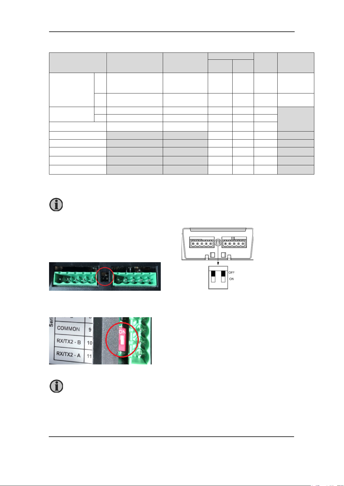
Dill switch
(red)
RS-485
termination
See picture
above
120 Ω termination resistor, default OFF.
The red dill switch is located above term. 10.
XDi-N connections on main unit
Overview for the two connectors on the main XDi-N unit.
no.
voltage
voltage
Note 1: By default, the CAN bus termination switch is set to “OFF”.
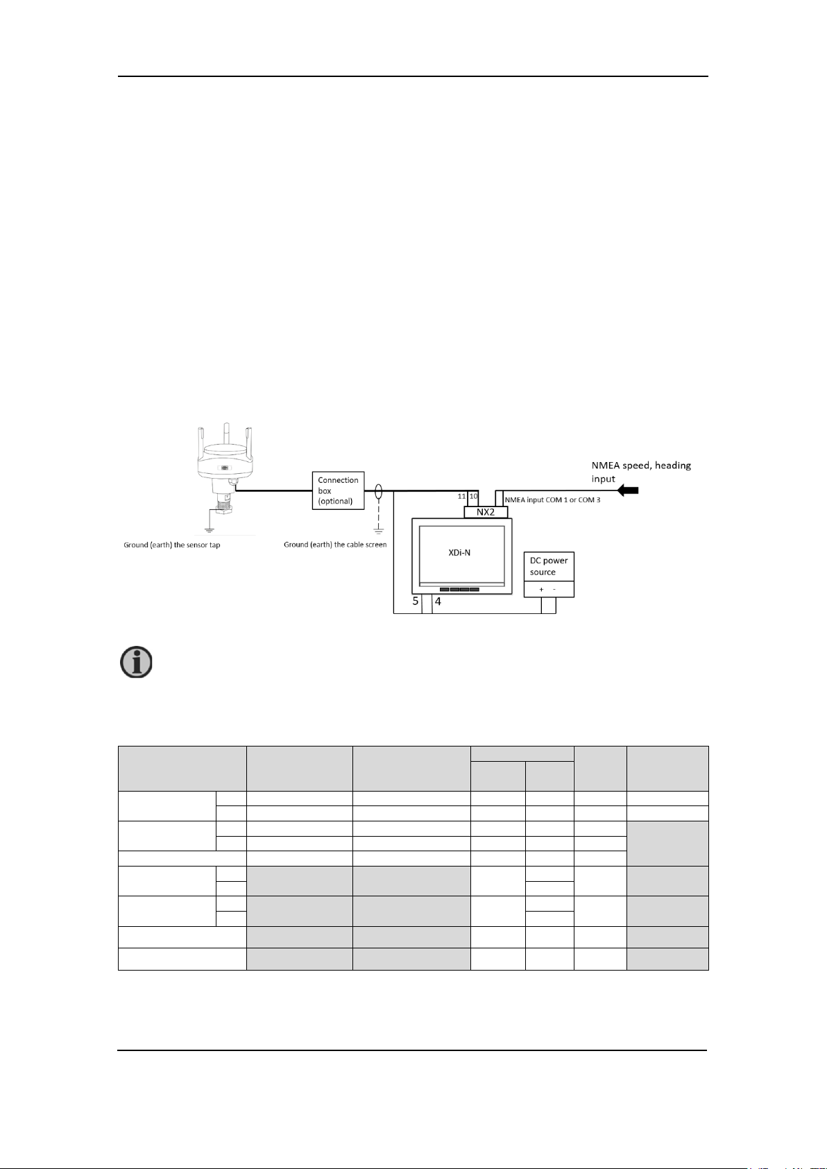
NX2 NMEA extension module connections
NX2 is the extension module enabling the XDi-N to receive
and transmit NMEA 0183 serial data (in accordance with
IEC61162-1 and -2).
When NX2 module is mounted in the extension slot, several
input/output ports are available for the serial NMEA 0183
data.
The different ports and terminal connections are shown in
the table below.
NMEA 0183
Note1: Common (Reference GND) for RS-485 COM port, COM 1 output and contact input.
DEIF A/S Page 8 of 69
Page 9
Wind Measuring Systems Application notes, using XDi-N indicators
WSS 550
cable colour
Function
Extension cable
wire colour
Note
Black
Supply voltage
-
Black
DC supply voltage for the wind sensor
Red + Red
Orange
RS-485 com
A
Orange
Wind speed and direction data output
Brown
B
Brown
Shield
Electrical shielding of
Shield
Shield is internally connected to the
any other ground or common terminal.
WSS 750
cable colour
Function
Extension cable
wire colour
Note
Grey/Pink and
Red, Yellow]
Supply voltage
-
Black
DC supply voltage for the wind sensor
White and
Pink]
+
Red
Red/blue (A)
RS-485 com
A
Orange
Wind speed and direction data output
Brown (B)
B
Brown
Shield
Electrical shielding of
Shield
Shield is internally connected to the
other ground or common terminal.
WSS 550 Wind sensor cable connections
data signal
must be
connected to
shield in the
sensor cable.
WSS 750 Wind sensor cable connections
stainless-steel mounting rod on the
wind sensor and must have a good
ground connection in the mast. The
cable shield is not to be connected to
[Blue, Black,
[Grey, Green
DEIF A/S Page 9 of 69
data signal
must be
connected to
shield in the
sensor cable.
stainless-steel housing of the wind
sensor and must have a good ground
connection in the mast. The cable
shield is not to be connected to any
Page 10

Wind Measuring Systems Application notes, using XDi-N indicators
Wind system accessories
Different length of extension cable for the sensor and a connection box is available as
accessories.
When using extension cable, it is important to read the installation guidelines in the wind sensor
documentation.
Other manufacturer’s wind sensors
The DEIF wind sensors shown in all the system applications in this document may be replaced
with a similar wind sensor from another manufacturer. The sensor must have either RS-422 or
RS-485 output, and it must output relative wind data sent in the NMEA 0183 MWV sentence. The
wind speed can be either m/s or knots.
If the sensor has an RS-422 output, it is recommended to connect it to one of the standard NMEA
inputs (input RX1 or RX3) on the NX2 module. If the interface is RS-485, use the same input as
the DEIF sensor (RX/TX2, RS-485).
DEIF A/S Page 10 of 69
Page 11
Wind Measuring Systems Application notes, using XDi-N indicators
WSS 550
Extension cable
XDi
NX2
Power supply
Supply voltage
-
Black
Black 5 -
0 V
+
Red
Red 4 -
+ 24 V DC
RS-485 com
A
Orange
Orange
-
11 B
Brown
Brown
-
10
Electrical shielding of
Shield
Shield
No connection
RS-485 termination
-
ON
WSS 750
Extension cable
XDi
NX2
Power supply
Supply voltage
-
Grey/Pink and [Blue,
Red, Yellow]
Black 5 -
0 V
+
White and
[Grey, Green, Pink]
Red 4 -
+ 24 V DC
RS-485 com
A
Red/blue (A)
Orange
-
11
B
Brown (B)
Brown
-
10
Electrical shielding of
Shield
Shield
No connection
RS-485 termination
-
ON
System applications
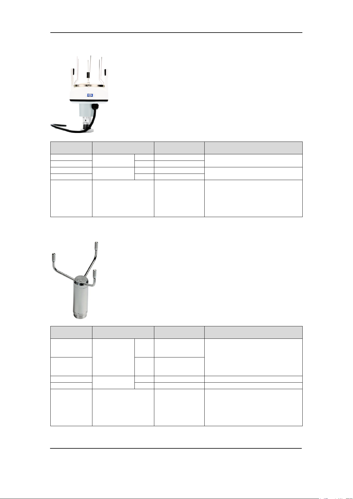
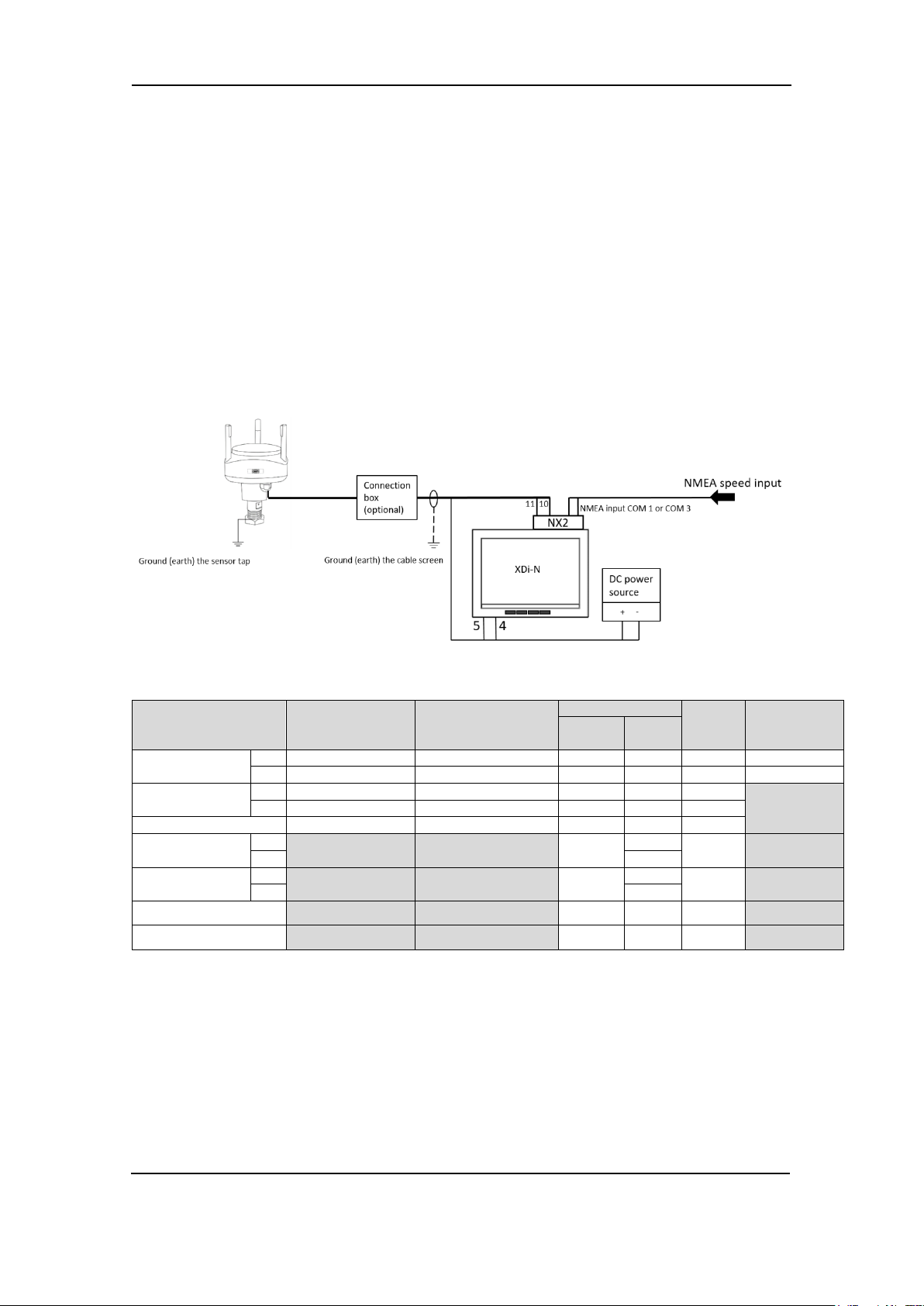
System 1 - Relative wind indicator system
This application describes the basic wind indicator system presenting only the relative (apparent)
wind speed and direction.
The XDi-N wind indicator receives the relative wind data via the RS-485 NMEA input from any of
the DEIF wind sensors, either the WSS 550 or WSS 750.
Connecting a WSS 550 standard wind system
Function
data signal
cable colour
wire colour
Connecting a WSS 750 high performance wind system
Function
cable colour
Black,
wire colour
term.
term.
term.
term.
data signal
DEIF A/S Page 11 of 69
Page 12

Wind Measuring Systems Application notes, using XDi-N indicators
Product Profile
Virtual indicator
VI setup
NMEA setup
PP01 – Front dimmer
VI 001 Wind indicator
FWD, Relative wind
VS02 NMEA1
Make an auto scan to set
up NMEA correctly
It is also possible to replace the DEIF wind sensor with another manufacturer’s wind
Terminate the RS-485 line from the sensor by shifting the red dill switch on the NX2 module to
ON. See picture.
sensor connected to the XDi-N, see section “Other manufacturer’s wind sensors”.
Installation setting
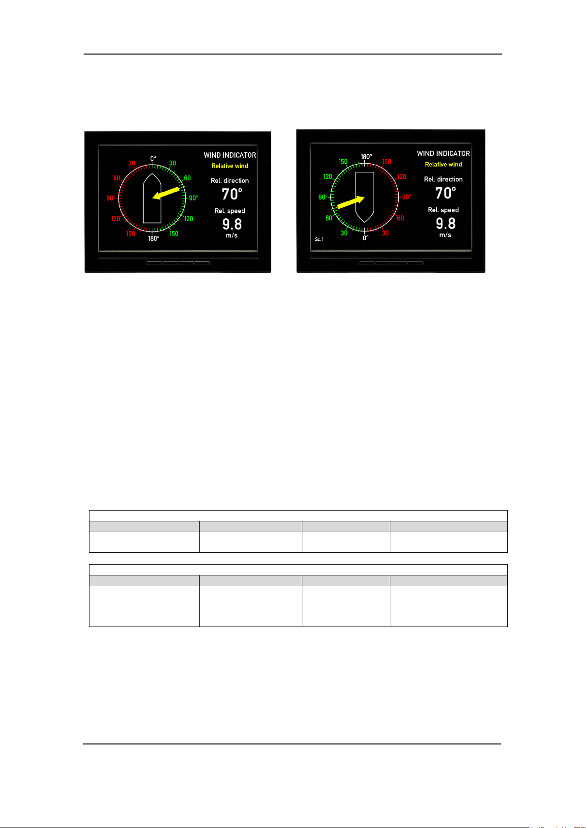
Using the DEIF standard wind library 001, different wind indicators can be selected during setup.
The library contains a design suitable for installation on a normal forward-looking bridge (forward)
as well as a design for mounting on an aft bridge.
Relative wind indicator forward bridge (VI001) Relative wind indicator aft bridge (VI002)
Dimming
Standard dimming of an XDi-N is done via the two centre buttons on the front of the XDi-N unit.
Alternatively, the XDi-N can be set up for external dimming control from either push-buttons or
potentiometer, please see appendix 4 for details.
Installation wizard
When the XDi-N has not yet been set up, it will automatically start the start-up wizard. The
selections to be made in the start-up wizard to activate dimming from front buttons and select the
relative wind indicator for a forward bridge location is shown in the table below.
Select a CAN NodeID.
In this system, CAN/XDi-net is not used, so just press OK to select the default CAN NodeID = 40.
Select virtual indicator and profiles
Please find the detailed first-time setup procedure in Appendix 1.
DEIF A/S Page 12 of 69
Page 13
Wind Measuring Systems Application notes, using XDi-N indicators
WSS 550
Extension cable
XDi 1
XDi 2
term.
Power
Main
term.
NX2
term.
Supply voltage
-
Black
Black 5 -
5
0 V
+
Red
Red 4 -
4
+ 24 V DC
RS-485 com
A
Orange
Orange
-
11
-
B
Brown
Brown
-
10
-
Cable shield
Shield
Shield - -
-
CAN 1 Low
1 - 1
CAN 1 High
2 - 2
CAN cable shield
-
-
CAN 1 termination
ON
-
ON
RS-485 termination
-
ON
-
It is possible to extend this system with additional XDi-N indicators. They must be set
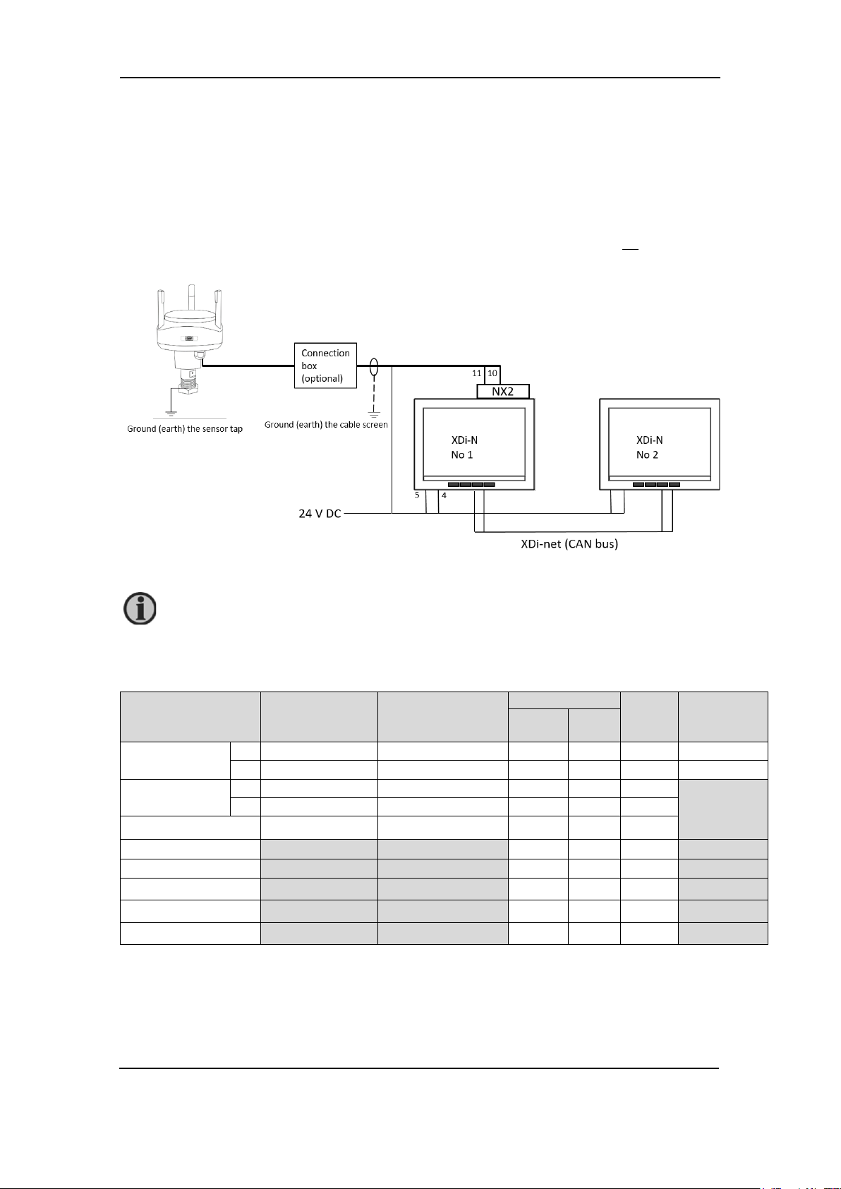
System 2 - Dual relative wind indication
This application is used on ships where there is a need for an extra wind indicator. The extra
indicator can be a normal forward type or the version for aft bridge.
The first XDi-N, called the main unit, receives relative wind data via the RS-485 NMEA input from
any of the DEIF wind sensors, either the WSS 550 or WSS 750. The received wind data is shared
on XDi-net.
The second XDi-N receives wind data via XDi-net (CAN bus 1). This means that no NX2 module
is needed on this unit.
Connecting a WSS 550 standard wind system
Function
up as XDi-N no. 2 in the described system, but only the last XDi-N on the CAN bus is
to be terminated.
cable colour
wire colour
Main
supply
DEIF A/S Page 13 of 69
Page 14
Wind Measuring Systems Application notes, using XDi-N indicators
WSS 750
Extension
wire colour
XDi 1
XDi 2
term.
Power
Main
term.
NX2
term.
Supply voltage
-
Grey/Pink and
Red, Yellow]
Black 5 -
5
0 V
+
White and
[Grey, Green, Pink]
Red 4 -
4
+ 24 V DC
RS-485 com
A
Orange
Orange
-
11
-
B
Brown
Brown
-
10
-
Cable shield
Shield
Shield - -
-
CAN 1 Low
1 - 1
CAN 1 High
2 - 2
CAN cable shield
-
-
CAN 1 termination
ON
-
ON
RS-485 termination
-
ON
-
Use a twisted pair shielded cable for the CAN bus connection. The built-in termination
It is also possible to replace the DEIF wind sensor with another manufacturer’s wind
Connecting a WSS 750 high performance wind system
Function
Please see appendix 5 for more information of correct installation of a CAN bus/XDi-net system.
switch must be set to ON in both XDi-N indicators in this installation. You find the small
switch between the two connectors on the XDi-N unit.
cable colour
[Blue, Black,
cable
Main
supply
Terminate the RS-485 line from the sensor by shifting the red dill switch on the NX2 module to
ON. See picture.
DEIF A/S Page 14 of 69
sensor connected to the XDi-N, see section “Other manufacturer’s wind sensors.
Page 15
Wind Measuring Systems Application notes, using XDi-N indicators
Indicator 1
Product Profile
Virtual indicator
VI setup
NMEA setup
PP01 – Front dimmer
Group 1*
VI001
Forward relative wind
VS02 NMEA1
Make an auto scan to set
up NMEA correct
Indicator 2
Product Profile
Virtual indicator
VI setup
NMEA setup
PP01 – Front dimmer
VI001 or VI002
selected
VS01 XDi-net
No NMEA setup is
the setup.
Installation setting
Using the DEIF standard wind library 001, different wind indicators can be selected during setup.
The library contains a design suitable for installation on a normal forward-looking bridge (forward)
and a design for mounting on an aft bridge.
Relative wind indicator forward bridge (VI001) Relative wind indicator aft bridge (VI002)
Dimming
Dimming from the front buttons is selected in this application for both indicators. Since they are
connected via XDi-Net (CAN), the dimmer level will be synchronised between the two indicators,
since by default, they are assigned to dimmer group 1.
See other dimmer alternatives in Appendix 4.
Installation wizard
When the XDi-N has not yet been set up, it will automatically start the start-up wizard.
In the table below, you find the correct wizard setup for this system with either two forward wind
indicators or one forward and one aft indicator.
Select a CAN NodeID.
In this application, XDi-net (on CAN bus) is used to share data with other wind indicators in the
system. The two indicators must have different CAN NodeID. It is not important which ID you
select for the two as long as they are different. Select for example 40 (default) and 41.
Select virtual indicator and profiles
Group 1*
*) Select PP03 “Local Dimmer” instead of PP01, to have individual dimmer on the two XDi-N
indicators.
Please find the detailed first-time setup procedure in Appendix 1.
DEIF A/S Page 15 of 69
Forward or AFT
indicator can be
possible.
Select Finish to complete
Page 16
Wind Measuring Systems Application notes, using XDi-N indicators
WSS 550
Extension cable
XDi 1
XDi 2
term.
Power
Main
term.
NX2
term.
Supply voltage
-
Black
Black 5 - 5 0 V
+
Red
Red 4 - 4 + 24 V DC
RS-485 com
A
Orange
Orange
-
11
- B
Brown
Brown - 10
-
Cable shield
Shield
Shield - -
-
RX1 (COM1)
NMEA input 1
A
- 2 B
1
RX3 (COM3)
NMEA input 1
A
- 4 B
3
NMEA cable shield
- - -
System 3 - Relative and true wind indication
In this application, the XDi-N indicator is able to present both the relative (apparent) wind speed
and direction and in addition, the true wind speed and direction relative to the bow of the ship
(see Appendix 6 for definitions of true wind).
The XDi-N wind indicator receives the relative wind data via the RS-485 NMEA input from any of
the DEIF wind sensors, either the WSS 550 or WSS 750.
XDi-N can calculate the true wind data if the ship’s speed data is available from the speed log or
navigation system. Both speed over ground and speed through water can be used for the
calculation.
XDi-N can receive speed data if an NMEA output providing the speed data is connected to one
of the two standard NMEA inputs on the NX2 module (RX1 or RX3). The following NMEA
sentences may contain the ship’s speed and can be used as input to the true wind calculation:
VHW, VBW, VTG, RMC.
Connecting a WSS 550 standard wind system
Function
RS-485 termination
cable colour
wire colour
Main
- ON -
supply
DEIF A/S Page 16 of 69
Page 17
Wind Measuring Systems Application notes, using XDi-N indicators
WSS 750
Extension
wire colour
XDi 1
XDi 2
term.
Power
Main
term.
NX2
term.
Supply voltage
-
Grey/Pink and
Red, Yellow]
Black 5 - 5 0 V
+
White and
[Grey, Green, Pink]
Red 4 - 4 + 24 V DC
RS-485 com
A
Orange
Orange
-
11
-
B
Brown
Brown
-
10
-
Cable shield
Shield
Shield - -
-
RX1 (COM1)
NMEA input 1
A
- 2 B
1
RX3 (COM3)
NMEA input 1
A
- 4 B
3
- - -
It is also possible to replace the DEIF wind sensor with another manufacturer’s wind
Connecting a WSS 750 high performance wind system
Function
NMEA cable shield
RS-485 termination
cable colour
[Blue, Black,
cable
Main
- ON -
supply
sensor connected to the XDi-N, see section “Other manufacturer’s wind sensors.
Installation and setting
Using the DEIF standard wind library 001, different wind indicators can be selected during setup.
The library contains a design suitable for installation on a normal forward-looking bridge (forward)
and a design for mounting on an aft bridge.
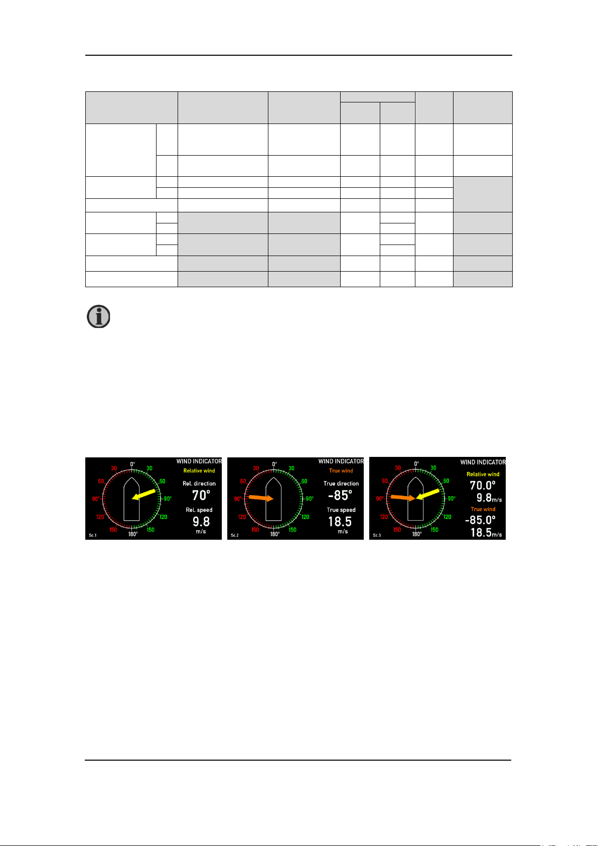
A standard indicator for this application can be VI003 wind relative and true FWD. This indicator
has 3 screens that can be toggled between using the left push-button on the front of the XDi-N.
(Toggle between the screens is also possible from an external push-button).
Toggle between the three screens showing: relative wind, true wind and a combination of
relative and true wind.
Dimming
Standard dimming of the XDi-N is done via the two centre buttons on the front of the XDi-N unit.
Alternatively, the XDi-N can be set up for external dimming control from either push-buttons or
potentiometer, please see Appendix 4 for details.
Installation wizard
When the XDi-N has not yet been set up, it will automatically start the start-up wizard. Settings to
be selected in the start-up wizard to show the relative and true wind indication for a forward bridge
with dimming controlled using front buttons is seen in the table below.
Select a CAN NodeID.
In this system, CAN/XDi-net is not used, so just press OK to select the default CAN NodeID = 40.
DEIF A/S Page 17 of 69
Page 18

Wind Measuring Systems Application notes, using XDi-N indicators
Product Profile
Virtual indicator
VI-Setup
NMEA Setup
PP01 – Front dimmer
VI 003
VS03 NMEA 2
Make an auto scan to set up NMEA
needed.
Select virtual indicator and profiles
Relative and true
wind, FWD
calculate
correctly.
Some manual selections might be
Please find the detailed first-time setup procedure in Appendix 1.
DEIF A/S Page 18 of 69
Page 19
Wind Measuring Systems Application notes, using XDi-N indicators
WSS 550
Extension cable
XDi 1
XDi 2
term.
Power
Main
term.
NX2
term.
Supply voltage
-
Black
Black 5 - 5 0 V
+
Red
Red 4 - 4 + 24 V DC
RS-485 com
A
Orange
Orange
-
11
- B
Brown
Brown
-
10
-
Cable shield
Shield
Shield - -
-
RX1 (COM1)
NMEA input 1
A
- 2 B
1
RX3 (COM3)
NMEA input 1
A
- 4 B
3
Instead of calculating true and geographic true wind, the XDi-N can also receive those
System 4 - relative, true and geographic true wind indication
In this application, the three XDi screens from system 3 are extended with one screen more
presenting geographic true wind (see Appendix 6 for definitions of true wind).
The XDi-N wind indicator receives the relative wind data via the RS-485 NMEA input from any of
the DEIF wind sensors, either the WSS 550 or WSS 750.
The XDi-N can calculate the true wind data if the ship’s speed and heading data is available from
the speed log, heading compass or navigation system. Both speed over ground and speed
through water can be used for the calculation.
To be able to calculate true wind, the XDi-N must receive speed and heading data from the ship’s
systems connected to the standard NMEA inputs on the NX2 module (RX1 and/or RX3).
The following NMEA sentences contain the ship’s speed and heading information used as input
to the true and geographic true wind calculation.
Speed: VHW, VBW, VTG, RMC
Heading: HMR, THS, HTD, VHW, HDT, HDG
Magnetic variation: HMR, RMC, HDG (this parameter is used to calculate between magnetic and
true heading)
data directly from another system connected to one of the NMEA inputs. The NMEA
sentence must be MWD (geographic) and MWV (true).
Connecting a WSS 550 standard wind system
Function
NMEA cable shield - - -
RS-485 termination
cable colour
wire colour
-
ON -
Main
supply
DEIF A/S Page 19 of 69
Page 20
Wind Measuring Systems Application notes, using XDi-N indicators
WSS 750
Extension
wire colour
XDi 1
XDi 2
term.
Power
Main
term.
NX2
term.
Supply voltage
-
Grey/Pink and
Red, Yellow]
Black 5 - 5 0 V
+
White and
[Grey, Green, Pink]
Red 4 - 4 + 24 V DC
RS-485 com
A
Orange
Orange
-
11
-
B
Brown
Brown
-
10
-
Cable shield
Shield
Shield - -
-
RX1 (COM1)
NMEA input 1
A
- 2 B
1
RX3 (COM3)
NMEA input 1
A
- 4 B
3
- - -
It is also possible to replace the DEIF wind sensor with another manufacturer’s wind
Connecting a WSS 750 high performance wind system
Function
NMEA cable shield
RS-485 termination
cable colour
[Blue, Black,
cable
-
Main
ON -
supply
sensor connected to the XDi-N, see section “Other manufacturer’s wind sensors.
Installation and setting
Using the DEIF standard wind library 001, different wind indicators can be selected during setup.
The library contains a design suitable for installation on a normal forward-looking bridge (forward)
and a design for mounting on an aft bridge.
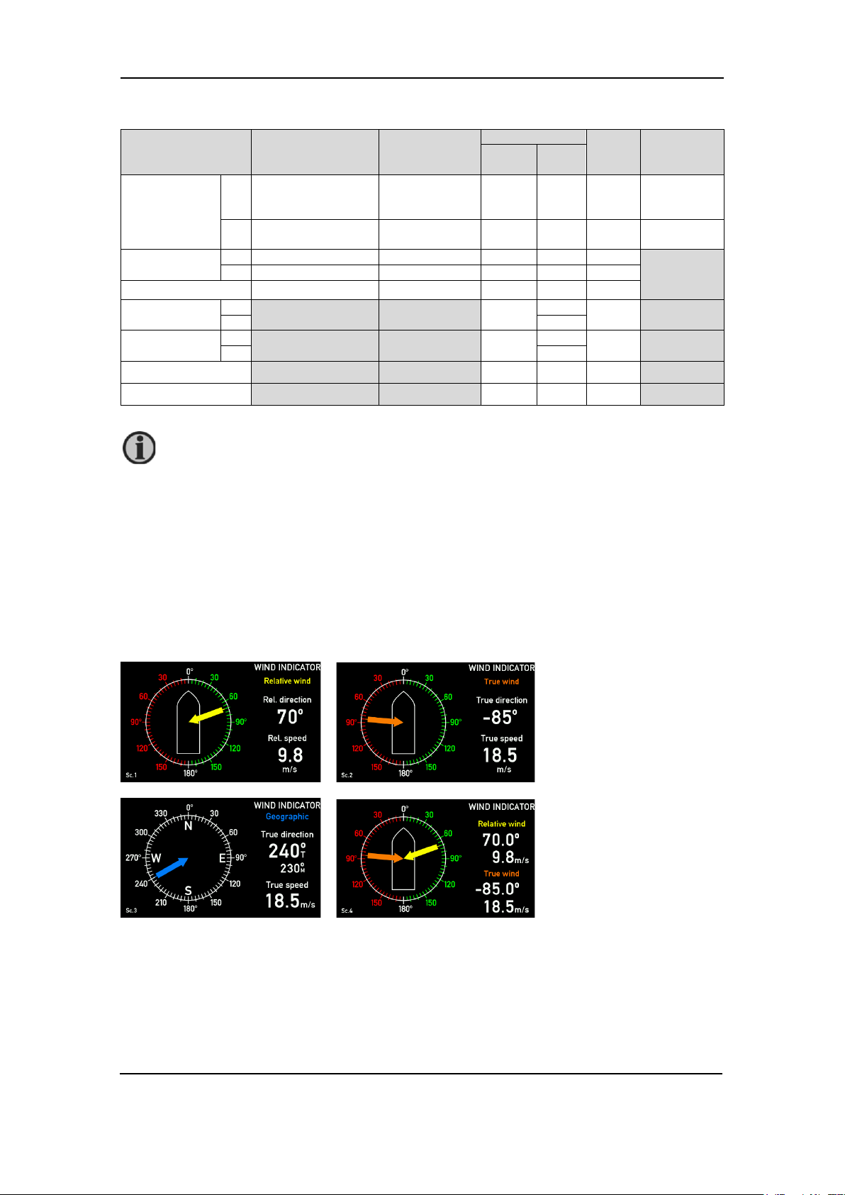
A standard indicator for this application can be VI005 wind relative and true FWD. This indicator
has 4 screens that can be toggled between using the left push-button on the front of the XDi-N.
(Toggle between the screens is also possible from an external push-button).
Use the left button on the front to toggle between the four screens showing: relative wind, true
wind, geographic true wind and a combination of relative and true wind.
DEIF A/S Page 20 of 69
Page 21

Wind Measuring Systems Application notes, using XDi-N indicators
Product Profile
Virtual indicator
VI setup
NMEA setup
PP01 – Front dimmer
VI 007
(XDi 96 N use VI05)
VS03 NMEA 2
Make an auto scan to set up NMEA
needed.
Product Profile
Virtual indicator
VI-Setup
NMEA Setup
PP01 – Front dimmer
VI 005
VS03 NMEA 2
Make an auto scan to set up NMEA
needed.
Dimming
Standard dimming of the XDi-N is done via the two centre buttons on the front of the XDi-N unit.
Alternatively, the XDi-N can be set up for external dimming control from either push-buttons or
potentiometer, please see Appendix 4 for details.
Installation wizard
When the XDi-N has not yet been set up, it will automatically start the start-up wizard.
Settings to be selected in the start-up wizard to show a wind system presenting relative, true and
geographical wind for a forward bridge with dimming controlled using front buttons is seen in the
tables below.
Select a CAN NodeID.
In this system, CAN/XDi-net is not used, so just press OK to select the default CAN NodeID = 40.
Select virtual indicator and profiles
For a wind system where, geographic wind is presented relative to true north, select:
Relative and true
wind, FWD
Calculate
correctly.
Some manual selections might be
For a wind indicator system where geographic wind is presented relative to both true north and
magnetic north, select:
Relative and true
wind, FWD
Calculate
correctly.
Some manual selections might be
This selection is not available for XDi 96 N.
Please find the detailed first-time setup procedure in Appendix 1.
DEIF A/S Page 21 of 69
Page 22

Wind Measuring Systems Application notes, using XDi-N indicators
It is possible to extend this system with additional XDi-N indicators. They must be set
System 5 - dual relative, true and geographical wind indication
This application is a double indicator version of system 4 presenting relative, true and geographic
true wind on two XDi-N indicators (see Appendix 6 for definitions of true wind).
The XDi-N wind indicator receives the relative wind data via the RS-485 NMEA input from any of
the DEIF wind sensors, either the WSS 550 or WSS 750.
The XDi-N can calculate the true wind data if the ship’s speed and heading data is available from
the speed log, heading compass or navigation system. Both speed over ground and speed
through water can be used for the calculation.
To be able to calculate true wind, the XDi-N must receive speed and heading data from the ship’s
systems connected to the standard NMEA inputs on the NX2 module (RX1 and/or RX3).
The following NMEA sentences contain the ship’s speed and heading information used as input
to the true and geographic true wind calculation.
Speed: VHW, VBW, VTG, RMC
Heading: HMR, THS, HTD, VHW, HDT, HDG
Magnetic variation: HMR, RMC, HDG (this parameter is used to calculate between magnetic and
true heading).
The relative wind data inclusive sensor direction alignments and the calculated wind data is
shared on the XDi-net to make the system integration easy.
up as XDi-N no. 2 in the described system, but only the last XDi-N on the CAN bus is
to be terminated.
DEIF A/S Page 22 of 69
Page 23

Wind Measuring Systems Application notes, using XDi-N indicators
WSS 550
Extension cable
XDi 1
XDi 2
term.
Power
Main
term.
NX2
term.
Supply voltage
-
Black
Black 5 - 5 0 V
+
Red
Red 4 - 4 + 24 V DC
RS-485 com
A
Orange
Orange
-
11
- B
Brown
Brown
-
10 - Cable shield
Shield
Shield - -
-
RX1 (COM1)
NMEA input 1
A
- 2 B
1
RX3 (COM3)
NMEA input 1
A
- 4 B
3
- - -
WSS 750
Extension
wire colour
XDi 1
XDi 2
term.
Power
Main
term.
NX2
term.
Supply voltage
-
Grey/Pink and
Red, Yellow]
Black 5 - 5 0 V
+
White and
[Grey, Green, Pink]
Red 4 - 4 + 24 V DC
RS-485 com
A
Orange
Orange
-
11
- B
Brown
Brown
-
10
-
Cable shield
Shield
Shield - -
-
RX1 (COM1)
NMEA input 1
A
- 2 B
1
RX3 (COM3)
NMEA input 1
A
- 4 B
3
- - -
It is also possible to replace the DEIF wind sensor with another manufacturer’s wind
Connecting a WSS 550 standard wind system
Function
NMEA cable shield
CAN 1 termination
RS-485 termination
cable colour
wire colour
Connecting a WSS 750 high performance wind system
Function
cable colour
[Blue, Black,
cable
Main
ON - ON
-
ON -
Main
supply
supply
NMEA cable shield
CAN 1 termination
RS-485 termination
ON - ON
- ON -
sensor connected to the XDi-N, see section “Other manufacturer’s wind sensors.
Installation and setting
Using the DEIF standard wind library 001, different wind indicators can be selected during setup.
The library contains a design suitable for installation on a normal forward-looking bridge (forward)
and a design for mounting on an aft bridge.
A standard indicator for this application can be VI005 wind relative and true FWD. This indicator
has 4 screens that can be toggled between using the left push-button on the front of the XDi-N.
(Toggle between the screens is also possible from an external push-button).
DEIF A/S Page 23 of 69
Page 24

Wind Measuring Systems Application notes, using XDi-N indicators
Indicator 1
Product Profile
Virtual indicator
VI setup
NMEA setup
PP01 – Front dimmer
VI 007
VI05)
VS03 NMEA 2
Make an auto scan to set up NMEA
Indicator 2
Product Profile
Virtual indicator
VI setup
NMEA setup
PP01 – Front dimmer
VI007 Forward or
VI05 or VI06)
VS01 XDi-net
No NMEA setup is possible.
Toggle between the four screens
showing: relative wind, true wind, geographic true wind and a
combination of relative and true wind.
Dimming
Standard dimming of XDi-N is done via the two centre buttons on the front of the XDi-N unit.
Alternatively, the XDi-N can be set up for external dimming control from either push-buttons or
potentiometer, please see Appendix 4 for details.
Installation wizard
When the XDi-N has not yet been set up, it will automatically start the start-up wizard.
Settings to be selected in the start-up wizard to show a dual relative true and geographical wind
indication system for a forward bridge with dimming controlled using front buttons is seen the
tables below.
Select a CAN NodeID.
In this application, XDi-net (on CAN bus) is used to share data with other wind indicators in the
system. The two indicators must have different CAN NodeID. It is not important which ID you
select for the two as long as they are different. Select for example 40 (default) and 41.
For a wind system, where geographic wind is presented relative to true north, select:
Group 1*
DEIF A/S
Page 24 of 69
Relative and true
wind, FWD
(For XDi 96 N, use
VI008 Aft indicator
can be selected
(For XDi 96 N, use
Calculate
correctly.
Some manual selection might be
needed
Select Finish to complete the setup.
Page 25

Wind Measuring Systems Application notes, using XDi-N indicators
Indicator 1
Product Profile
Virtual indicator
VI setup
NMEA setup
PP01 – Front dimmer
VI 005
VS03 NMEA 2
Make an auto scan to set up NMEA
needed.
Indicator 2
Product Profile
Virtual indicator
VI setup
NMEA setup
PP01 – Front dimmer
VI005 Forward or
can be selected
VS01 XDi-net
No NMEA setup is possible.
This selection is not available for XDi 96 N.
For a wind indicator system, where geographic wind is presented relative to both true north and
magnetic north, select:
Relative and true
wind, FWD
Calculate
correctly.
Some manual selections might be
Group 1*
VI006 Aft indicator
Select Finish to complete the setup.
Please find the detailed first-time setup procedure in Appendix 1.
DEIF A/S Page 25 of 69
Page 26

Wind Measuring Systems Application notes, using XDi-N indicators
System 6 - Wind system for bi-directional ferry (Ro-Ro)
When having a bi-directional ferry, the application below can be used. Here two forward XDi-N
indicators are used to show the relative wind.
The sketch shows a ro-ro ferry with two main indicators placed on the two bridge locations.
When the ferry is sailing in direction A, main indicator 1 is used for wind indication.
When the ferry is sailing in direction B, which is now becoming the bow, main indicator 2 is used
to show the wind direction.
One of the indicators must be set up so that the wind direction input has an offset of 180°.
System description
The two XDi-N indicators must both be mounted with an NX2 module. On Ro-Ro ferries, you can
say that the bow and stern shifts place depending on the actual sailing direction. There are two
manoeuvring consoles; one pointing one way and the other pointing the opposite way. Both
consoles have an overhead panel where the XDi-N is showing the correct wind speed and
direction. Only the relevant XDi-N indicator is used at a given time depending on the actual sailing
direction.
DEIF A/S Page 26 of 69
Page 27

Wind Measuring Systems Application notes, using XDi-N indicators
WSS 550
Extension
colour
XDi 1
XDi 2
Power
Main
term.
NX2
term.
Main
term.
NX2
term.
Supply voltage
-
Black
Black 5 - 5 -
0 V
+ 24 V
DC
RS-485 com
A
Orange
Orange
-
11 - 11
B
Brown
Brown - 10 - 10
Cable shield
Shield
Shield - - - -
RS-485 termination
- - -
ON
WSS 750
Extension
XDi 1
XDi 2
Power
Main
term.
NX2
term.
Main
term.
NX2
term.
Supply
-
Grey/Pink and
Red, Yellow]
Black 5 - 5 -
0 V
+
White and
Pink]
Red 4 - 4 -
+ 24 V
RS-485
A
Orange
Orange
-
11 - 11
B
Brown
Brown - 10 - 10
- - -
-
RS-485
termination
It is also possible to replace the DEIF wind sensor with another manufacturer’s wind
Do not connect the CAN bus between the two XDi-N indicators. Due to the data sharing
disable XDi-net sharing of relative wind speed and direction data on both XDi-N units.
Connecting a WSS 550 standard wind system
Function
+ Red Red 4 - 4 -
cable
colour
cable
wire
Connecting a WSS 750 high performance wind system
Function
voltage
com
Cable shield Shield Shield
cable colour
[Blue, Black,
[Grey, Green,
cable
wire colour
supply
supply
DC
- - - ON
sensor connected to the XDi-N, see section “Other manufacturer’s wind sensors.
on XDi-net, the wind direction will fluctuate on both indicators.
If you want to use the CAN bus for network dimming of both XDi-N units, you must
Installation setting
Using the DEIF standard wind library 001, different wind indicators can be selected during setup.
Both XDi-N units should in this application use the forward wind indicator VI001.
Relative wind indicator forward bridge (VI001)
DEIF A/S Page 27 of 69
Page 28

Wind Measuring Systems Application notes, using XDi-N indicators
XDi No. 1
Product Profile
Virtual indicator
VI setup
NMEA setup
PP01 – Front dimmer
VI 001 wind indicator
FWD, relative wind
VS02 NMEA1
Make an auto scan to set
up NMEA correctly.
XDi No. 2
Product Profile
Virtual indicator
VI setup
NMEA setup
PP01 – Front dimmer
VI 001 wind indicator
FWD, relative wind
VS02 NMEA1
Make an auto scan to set
up NMEA correctly.
Dimming
Standard dimming of XDi-N is done via the two centre buttons on the front of the XDi-N unit.
Alternatively, the XDi-N can be set up for external dimming control from either push-buttons or
potentiometer, please see Appendix 4 for details.
Installation wizard
When the XDi-N has not yet been set up, it will automatically start the start-up wizard.
Settings to be selected in the start-up wizard to show the relative wind indicator for a ro-ro ferry
bridge installation with dimming controlled using front buttons is seen in the tables below.
Select a CAN NodeID.
In this system, CAN/XDi-net is not used, so just press OK to select the default CAN NodeID = 40
Select virtual indicator and profiles
Please find the detailed first-time setup procedure in Appendix 1.
When the NMEA setup is completed, the relative wind direction input to XDi-N no.2 must be set
up with an offset of 180°.
To set up the offset, follow the description below.
Adding offset to the wind direction
When you return from automatic NMEA setup to the menu “NMEA input setup”, select “Manual
input configuration…”
In this menu, select which one of the listed groups should be edited.
In this case, select the “WIND” group.
DEIF A/S Page 28 of 69
Page 29

Wind Measuring Systems Application notes, using XDi-N indicators
Note: No NMEA data for dimmer, speed and compass (heading) is needed in
this configuration so it is quite okay that the indications are red.
Select the input where the offset must be added.
Select “Wind direction R 1”.
Pressing OK will open the “NMEA input config” menu.
Select “Offset” to type in a value.
DEIF A/S Page 29 of 69
Page 30

Wind Measuring Systems Application notes, using XDi-N indicators
Enter the offset value.
The resolution of wind direction is 0.1 degree, so the resolution of the offset is also 0.1 degree.
This means that the +180° offset must be inserted as 1800.
This completes the installation.
To return to normal indicator mode, use the back button .
DEIF A/S Page 30 of 69
Page 31

Wind Measuring Systems Application notes, using XDi-N indicators
Output NMEA to other systems
When there is a requirement to send NMEA data to another system, for example VDR or
navigation system, this is easily done using the output port on the NX2 module. In the NMEA
output menu, there is a list of predefined output sentences to choose from.
When the wind direction is sent to the NMEA output on the NX2 module as described below, the
wind direction sent via NMEA will include the offset you may have inserted to correct for a
misaligned sensor.
The example below is used to explain the setup of the NMEA output function.
Here data is received from the wind sensor as relative wind and sent via NMEA to a VDR and
navigation system via the NX2 COM 1 output port (TX1).
Configure the NMEA output port
To select which NMEA sentence should be transmitted, the following steps must be performed.
NMEA output setup
The NMEA output menu is located in the NMEA setup menu in the install menu.
To select which NMEA sentence to be transmitted start by selecting “NMEA output setup…”
DEIF A/S Page 31 of 69
Page 32

Wind Measuring Systems Application notes, using XDi-N indicators
NMEA to be sent to output port
In the example, the data sentence “MWV Wind Speed and angle 1” (= instance 1) will be selected
and turned ON.
One MWV sentence will be sent containing the relative wind speed and direction.
If true wind is available in the configuration, then another MWV sentence will be sent containing
true wind speed and direction.
Please note that geographic true wind is contained in MWD not MWV. If geographic true wind
speed and direction is to be transmitted on the NMEA output, select “MWD-Wind direction and
speed 1” (instance 1).
Setting up the output port
The selection above will open the “NMEA Source setup”. Select Slot 2 Port 1 to be set to ON.
NMEA data will now be transmitted on TX1 output (COM 1) with the default 1000 ms transmit
interval.
If multiple NMEA sentences are set to ON, these will be transmitted on the COM port as individual
sentences with the respective sentence identifier.
DEIF A/S Page 32 of 69
Page 33

Wind Measuring Systems Application notes, using XDi-N indicators
Appendix 1 - XDi-N setup wizard and NMEA setup
XDi-N setup during installation
When the XDi-N is new and has not yet been set up, it will automatically start the setup wizard
when it is powered up. This wizard will guide you through the simple setup process.
The library owner number, type and number are indicated in the second line where you will also
find the library version number.
The library used in this example is the DEIF standard wind indicator library no. 001.
To continue making the setup, press the soft key button below the text “OK”.
Select CAN node ID
If the CAN bus/XDi-net is not used in your installation, please just press OK on the default CAN
NodeID to continue.
In a wind system with multiple XDi-N wind indicators, you can use XDi-net (on CAN) to make a
cost-effective and easy to install, plug and play system solution. In XDi-net, the CAN NodeIDs are
not important as long as they are different for each unit.
The first XDi-N unit to be set up during installation can be assigned the default CAN NodeID=40,
the next XDi-N can be assigned 41 and so on.
If by accident you select the same NodeID for two XDi-N units on the same CAN bus, you will see
the warning “CAN NodeID conflict” on the display, and the CAN port will not function until you
have selected a different CAN NodeID for each unit on the bus.
DEIF A/S Page 33 of 69
Page 34

Wind Measuring Systems Application notes, using XDi-N indicators
Select Product Profile (PP)
The product profile (PP) in an XDi-N library contains the setup parameters for all data types
supported by NMEA. It also contains all the default CAN bus setup parameters, default dimmer
and day/night shift setup parameters.
For each PP in the library, there is a description in the left side of the screen to help you make
the right choice. Select the product profile that fits your system and press OK.
Select virtual indicator (VI)
The next step is to select a virtual indicator (VI) from the library. The short description and
thumbnail picture helps you select the right one.
If the indicator contains more than one screen, the thumbnail picture will toggle between the
available screens. Select the VI by pushing the OK soft key.
Select virtual indicator setup (VS)
The VI setup (VS) defines the actual input setup for all pointers and digital readouts in the selected
virtual indicator, but also outputs from the indicator to other systems.
The selected virtual indicator VI007 has three VI-setup profiles, VS01, VS02 and VS03 to choose
from during installation.
VS01 profile is intended for use in a system where input data are received via XDi-net (CAN bus).
DEIF A/S Page 34 of 69
Page 35

Wind Measuring Systems Application notes, using XDi-N indicators
Speed and heading can also be received via XDi-net instead of via NMEA.
XDi-net data can come from the main XDi-N unit that is equipped with an NX2 NMEA extension
module, where wind sensor data and other NMEA data are received and then distributed via XDinet (CAN bus) to other XDi-N units on the same CAN bus.
This VS profile shall be used for the extra wind indicators in a wind indicator system with a main
indicator and one or several additional indicators.
An XDi-N unit that is set up to use the VS01 profile must not have an NMEA module attached.
Saving the NX2 module is what makes the XDi-net concept a cost-effective solution in wind
systems with two or more indicators.
In VS02, the inputs are default set up to receive the relative wind data from a wind sensor on S2.2
(Slot 2 port 2 – RS-485) and receive calculated wind data from another system via one of the
standard NMEA inputs, S2.1 or S2.3.
When using this profile, NMEA wind data can be retransmitted to the NMEA output (S2.1). From
the XDi-N installation menu, a relative wind direction offset can later be inserted to compensate
for a sensor misalignment.
The corrected wind direction will be presented on the indication and when used for retransmission
on the NMEA output. Retransmission to the NMEA output must be set up in the XDi-N installation
menu. An XDi-N wind indicator setup to use this type of NMEA input profile will act as the main
indicator unit in a wind indicator system, where it shares all relevant NMEA input data via XDinet, for other XDi-N units to use.
In VS03, the inputs are set up to receive wind data from a wind sensor connected to input S2.2
(Slot 2 port 2). Based on this, the XDi-N will calculate true wind speed and direction based on the
ship’s speed and heading data received via NMEA on either S2.1 or S2.3.
DEIF A/S Page 35 of 69
Page 36

Wind Measuring Systems Application notes, using XDi-N indicators
When using this profile, NMEA wind data can be retransmitted to the NMEA output (S2.1).
From the XDi-N installation menu, a relative wind direction offset can later be inserted to
compensate for a sensor misalignment.
The corrected wind direction will be presented on the indication and when used for retransmission
on the NMEA output. Retransmission to the NMEA output must be activated in the XDi-N
installation menu.
An XDi-N wind indicator setup to use this type of NMEA input profile will act as the main indicator
unit in a wind indicator system, and it will share all relevant NMEA input data and the calculated
true wind data via XDi-net, for other XDi-N units to use.
When the desired VS profile is highlighted, press OK to continue.
Finish or run NMEA setup
When the XDi-N is set up as an additional indicator without any NX2 NMEA extension module,
the wizard will not show the menu line “NMEA setup”, but instead highlight “Finish wizard”. Press
OK, and the selected virtual indicator will start and receive data from XDi-net.
Instead of finalising the setup, you may also access the user and installation menu directly from
this step, if additional setup or parameter adjustments are needed.
NMEA setup on a main XDi-N indicator
If the XDi-N is a main unit with an NX2 NMEA extension module mounted, the wizard will suggest
you to make an NMEA setup as the next task:
Before you push “OK”, it is a good idea to make sure that all relevant NMEA sensors and system
devices are connected to the relevant NMEA inputs on NX2 and that they are powered up and
transmitting data.
Then press OK to select the NMEA setup menu.
DEIF A/S Page 36 of 69
Page 37

Wind Measuring Systems Application notes, using XDi-N indicators
NMEA auto scan and input selection
The next step is to select the highlighted “Auto scan and input selection…” by pressing OK. This
function will now scan all input channels and look for all relevant NMEA sentences.
The “Manual input selection…” should first be used after the auto scan routine is performed.
“Manual input configuration…” can be used to configure an NMEA input where no sentence is
available when the input scanning is performed.
If the sensor and other data sources are connected to the correct inputs on the NX2 module, and
if there is only one data source for every relevant data type, then the auto scan function will
automatically detect and select them as source.
NMEA auto setup example
This example is for a main XDi-N wind indicator used in an application where relative wind data
is received from the wind sensor, and the true and geographic true wind data is calculated by the
XDi-N.
The XDi-N setup is: NodeID=40, PP01, VI007, VS03.
The wind data is coming from a DEIF WSS 550 wind sensor connected to RX/RTX 2 (RS-485)
on the NX2 mounted in slot 2 (in XDi, this input is presented as 2.2).
To calculate the true wind data, speed and heading information is required. In this example speed
and heading data is available on one NMEA output from the ship’s integrated navigation system.
This output is connected to the RX1 input on the NX2 module in slot 2 (in XDi presented as 2.1).
XDi/NX2: NMEA input S2.2 (sensor data):
Wind speed: $WIMWV,220.0,R,028.0,N,A*29
XDi/NX2: NMEA input S2.1 (Nav. data):
Speed data: $VDVBW,06.0,00.0,A,05.0,00.0,A,00.0,V,00.0,A*45
Heading: $HEHDT,194.2,T*21
We select auto scan by pushing the OK button, and the automatic NMEA input scanning is
performed.
DEIF A/S Page 37 of 69
Page 38

Wind Measuring Systems Application notes, using XDi-N indicators
After a short period of time, the numbers in the right side will be stable. This means that no new
data sources are detected.
“Supported data sources” are all the sources that can be set up for NMEA in the selected product
profile. Normally it covers all data types that the different indicators in the library will use. It also
includes the dimmer groups that can be controlled by NMEA. Normally, this figure is more than
what is needed for the selected indicator.
In this case, we have selected one of the most complex wind indicators that is able to present
relative wind and calculated true wind data, and it has found 8 usable data sources and autoselected all 8.
“Active inputs (Slot.RX)” show the ports that NMEA data is currently receiving from.
Stop scan - manual select
To see what is actually selected, highlight “Stop scan – manual select…” and press OK.
You will then get this picture:
RED dot means that no external sources are available, in this case for the dimmer data group.
YELLOW dot means that sources are available for some data in the group, but it should be
checked. Some data types may need manual selection or some may be missing.
GREEN dot means that all data types in this group have been assigned a source.
We can now look through the automatic selection and check that needed data has a source
assigned:
DEIF A/S Page 38 of 69
Page 39

Wind Measuring Systems Application notes, using XDi-N indicators
DIMMER
The dimmer group is red on the above display. That is because the XDi-N does not receive any
NMEA DDC sentences to control the dimmer. If we press OK on the dimmer group, it will open
and we can see that no NMEA sources are available.
In this case, it doesn’t matter since we have chosen a PP where dimming is controlled by the front
buttons.
SPEED
The speed group is green, so everything is good. Speed data is needed to be able to calculate
the true wind data.
If we open this group, we can see which port and sentence is used to provide data.
In this case, “Speed through water (STW)” instance 1 and “Speed over ground (SOG)” instance
1, are received from input port 2.1, provided by talker VD, and sent in sentence VBW.
The XDi-N only needs one of the speed data to be able to calculate true wind. If STW is available,
it will by default be used. If not, SOG is used. Please note that the default selection can be
changed via the installation menu.
DEIF A/S Page 39 of 69
Page 40

Wind Measuring Systems Application notes, using XDi-N indicators
Please note that there is only one true wind speed parameter. It is the same
north poles.
WIND
This data group is yellow, so not all data is selected or manual setup is needed:
Relative wind speed and direction are received from the wind sensor connected to input port S2.2
and contained in the MWV sentence with talker WI. The selection is made automatically and
needs no further attention.
The “Wind speed T 1” and “Wind direction T1” (T= true) are marked in the menu as XDi-net.
The reason for this marking is that the internal wind calculator is active and delivers calculated
data as XDi-net data, for presentation on the indicator as well as transmitted on CAN bus using
the XDi-net protocol.
In this way, other XDi-N indicators on the CAN bus that are set up to receive XDi-net data will
present the same calculated wind data.
The geographic wind direction can be calculated both relative to the magnetic north pole and/or
to the geographic true north pole.
In this example, VI007 is selected and this indicator only presents the geographic true wind
direction relative to true north, therefore only “Wind direction GT 1” is calculated by the XDi-N.
The “Wind direction GM 1” which references to magnetic north is not used and therefore “No
NMEA” is indicated.
independently of the reference point used for the wind direction (ship’s heading or the
COMPASS
Compass data is used to calculate geographic true wind inside the XDi-N.
The compass group is also yellow and should therefore be checked:
DEIF A/S Page 40 of 69
Page 41

Wind Measuring Systems Application notes, using XDi-N indicators
When you leave the menu, the NMEA settings will be stored and locked. This means
The magnetic heading of the ship, “Heading M1”, is not available on NMEA, but it is not needed
in the actual configuration.
The true heading, “Heading T1” is received from the navigation system connected to input port
S2.1, provided by talker HE and contained in sentence HDT.
When the magnetic variation, “Mag. Var. 1” parameter is available on NMEA, the XDi-N is able to
calculate the magnetic compass heading based on the true heading (Heading T1) or the other
way around. If for example magnetic heading was calculated based on the HDT data available, it
will be shown as HE HDTcc (cc for calculated).
Finish the installation
The NMEA setup has now been verified and all data needed to show relative wind data and to
calculate true wind data is available, and all left to do is to press the return arrow until the wind
indicator is shown on the display and presents wind data.
that only the selected sources will be used by the XDi-N.
Change NMEA setup
If you make changes in your installation or want to change to another data source, you can always
access the installation menu and make changes.
How to access the installation menu
To access the installation menu, you must first enter the user menu. Press button 4 shortly and
go down to the last point in the quick menu to access the user menu. You can also press button
1 and 4 simultaneously for approximately 5 seconds to open the user menu.
When the user menu is open, you must push the “secret buttons” 2 and 3 for more than 5 seconds
to open the installation menu.
The installation menu contains the following points:
• Restart Setup Wizard
• Edit virtual indicator
• Adjust Input
• Adjust Output
• NMEA setup
• CAN bus setup
• Service
DEIF A/S Page 41 of 69
Page 42

Wind Measuring Systems Application notes, using XDi-N indicators
To change the NMEA setup, you must highlight NMEA setup and press OK:
Select NMEA setup….
If a new NMEA source is added or a source is moved to another input port, you must run the auto
scan again to update the list of available data sources.
Please note that the XDi-N is not allowed to make source changes automatically, even if it is no
longer available. The XDi-N will keep the locked source selection until you change it manually.
To change a source, you must enter the manual input selection menu, open the data group where
you want to make a change and then open the actual data type to select another source.
If you cannot find the NMEA source in the list and you know it is active on an input port, you can
run the auto scan function again. If it is still not showing up, you can check if the NMEA data is
actually received or not. For this, use the NMEA monitor function in the service menu.
See Appendix 3.
When is it necessary to make a manual setup?
It is necessary to scan the NMEA inputs again and make a manual setup:
• if you move the data source to another input port
• if you change the unit sending NMEA data with a device that has a different talker ID
• If a new device provides NEMA data in a different NMEA sentence type
Master reset
By pushing button 1 and 3 simultaneously for more than 5 seconds, you can make a master reset
and bring the unit back to the factory default settings.
It may be a good idea to make a master reset and start from the beginning:
• I If you have made big changes in the NMEA installation
• Moved the XDi-N from one system to another
Master reset is the only way to completely clear the source selections and start over from scratch.
DEIF A/S Page 42 of 69
Page 43

Wind Measuring Systems Application notes, using XDi-N indicators
Adjust wind direction input to correct sensor misalignment
If the wind sensor was incorrectly aligned when it was mounted in the mast top, it is easier to
make an angle correction in the XDi-N instead of climbing the mast again.
Enter the installation menu and select “NMEA input setup”:
Select “Manual input configuration…”
Select the “WIND” data group
DEIF A/S Page 43 of 69
Page 44

Wind Measuring Systems Application notes, using XDi-N indicators
To correct the angle, select the “Wind direction R 1” (it is the relative wind direction instance 1).
Select the “Offset:” line and insert the angle correction. Be aware that the XDi-N is using 0.1
resolution of the angle, so a positive angle correction of +10.0 degrees must be entered as 100.
The offset is added to the received wind angle.
If the received wind angle is +70 degrees, then the correction of 100 (=10.0 degree) is added and
the wind indicator will show a relative wind direction of +80.0 degrees.
The corrected wind angle is distributed on CAN using the XDi-net protocol, and all XDi-N wind
indicators on the CAN bus will automatically present the correct wind angle.
The corrected wind angle will also be used if the XDi-N is set up to output relative wind on one of
the NMEA outputs.
However, if the NMEA routing function is used to distribute the relative wind data, this angle
correction will not be included. The received wind sentence will just be routed directly to the output
without any change.
It is possible to make an offset on all normal data types, but be aware of the resolution. It can be
different from data type to data type. You can find the resolution in the “XDi-net CANopen
reference manual 4189350066 UK.pdf”.
Changing filter settings
All standard parameters can be filtered to reduce fluctuations.
The filter function is calculating the average of the latest received input values, and the filter value
indicates the number of values used to calculate the average value.
DEIF A/S Page 44 of 69
Page 45

Wind Measuring Systems Application notes, using XDi-N indicators
Please note that relative wind speed and wind direction both have a filter value. It often
When the wind direction is received every second from the wind sensor, the filter value 8 means
that data is averaged over the last 8 measurements or over 8 seconds.
The other input configuration parameters
In this input configuration menu it is also possible to manually set up the input channel, the talker
ID and the sentence. You should only set up or change those parameters if you know what you
are doing.
It can however be useful in the situation where an NMEA sentence is not available when the auto
scan and setup process is performed during installation. Maybe the sensor is not added until later,
but the sentence and input port is known.
The hex value 0x39F1:0x02 in the top line is the data index and sub-index used to distribute data
on XDi-net.
In the last menu line, you can change or stop the distribution of this data type on XDi-net (CAN).
makes sense to filter harder on the wind direction than on wind speed.
Edit the indicator headline
The headline of the indicator can be changed from the XDi-N installation menu.
DEIF A/S Page 45 of 69
Page 46

Wind Measuring Systems Application notes, using XDi-N indicators
Select the menu “Edit virtual indicator” and then select menu points:
- Text and units
- Headlines
You will now see:
Press “OK” to select a new headline text from the list of predefined headlines:
Alternatively, select “Add new text” to enter a new headline using the virtual keyboard.
It is also possible to make the headline invisible.
DEIF A/S Page 46 of 69
Page 47

Wind Measuring Systems Application notes, using XDi-N indicators
Appendix 2 – Normal operation of XDi-N
Toggle between screens
The XDi-N can have up to 4 screen modes for a virtual indicator and some of the standard wind
indicators have 2, 3 or 4 screens presenting different wind data types or combinations.
By default, each mode has one screen assigned. This means that when you toggle between the
modes, the screen will shift.
Press the left button (1) shortly to highlight the help menu bar and then press again to toggle to
the next screen.
Pushing several times when the help menu is visible will toggle you through all the available
screens.
Using mode shift in system integration
Normally the mode function is set up as local, which means that only the XDi-N where you have
pushed the button will shift screen.
In CAN bus systems, the mode function can be grouped much like the dimmer function and this
means that all indictors in a mode group will shift screen simultaneously.
In a wind system, this function can be used to shift all indicators to show the right wind indicator
screen in a given work situation.
For example steaming mode, work mode 1, work mode 2 and harbour mode.
For each XDi-N in a mode group, each mode can have a screen assigned via menu. The same
screen can even be used in more than one mode if needed.
This mode grouping function can be used to make quite advanced systems where a combination
of different XDi-N indicators form an information system where the right data are presented for
the actual work situation.
Mode can be shifted using the front buttons on any XDi-N in the mode group, via the external
connector inputs on the NX2 (or NX1) modules or as a CAN bus command from a central system.
It is even possible to define a custom profile so that the mode can be set from the digital inputs
on the DX1 module as a binary value from 0 to 3.
Dimmer up/down
Use the push-buttons below the symbols to dimmer up or down:
Press shortly to adjust the dimmer level one step at a time or keep pushing the button to make
larger adjustmets.
The actual dimmer level is shown in the right side of the menu bar:
Level 100 is maximum backlight and 0 is the minimum level.
DEIF A/S Page 47 of 69
Page 48

Wind Measuring Systems Application notes, using XDi-N indicators
The active profile can also be
Profile mode can be “Local” or
n global mode, this indicator is
the next chapter).
Change the wind speed unit
The XDi-N supports different selectable data units. The default presentation units are predefined
in the three unit profiles. In the standard wind indicators it is the wind speed unit that is selectable
via the unit profiles. Each unit profile contains default setup for all selectable data units that the
XDi-N supports.
The default setup for the wind indicator is:
Profile 1: Wind speed in m/s
Profile 2: Wind speed in knots
Profile 3: Wind speed in Beaufort
The default profile when the XDi-N wind indicator is installed is unit profile 1. This means that
wind speed is presented in m/s.
To shift to knots, you must select unit profile 2. To do that press the right button shortly once to
have the soft key menu presented, and push the right button again to open the quick
menu.
To toggle to Profile 2, push the “OK” button shortly and push the left button to go back to
normal operation.
Change unit in a unit profile
Wind speed can be presented in the following units: m/s, knot, Beaufort, km/h, MPH. To change
the wind speed unit in one of the unit profiles, select “Unit profile” in the quick menu, and highlight
the profile that you want to edit. Press OK to open the profile
for editing.
Highlight and press OK on Profile 2 to open it for editing:
changed from this menu.
“Global”.
In local mode, only this indicator is
affected by a profile shift.
I
synchronised with other indicators
on the CAN bus (see description in
DEIF A/S Page 48 of 69
Page 49

Wind Measuring Systems Application notes, using XDi-N indicators
The profile name can be edited by
highlighting and pressing OK. The
virtual keyboard will appear, and a
more informative name for the unit
profile can be typed in.
Highlight “Wind speed unit” and press OK:
It is now possible to select another unit from the list.
Change unit profile in a CAN bus system
The advanced XDi-net functions allow all indicators connected via CAN to make a simultaneous
shift of unit profile. XDi-N indicators where the unit profile selection and setup are to be
synchronised must have their profile mode changed from “Local” to “Global” in the UNIT
PROFILES menu above.
If the unit profile is changed for one unit on CAN, then all other global units will follow. Change of
presentation unit in one profile will also be synchronised to all other global units on the CAN bus.
This feature can also be quite useful in a wind indicator system with several XDi-N indicators.
Quick menu
The quick menu opens for the basic user setup functions:
- Unit profile toggle,
- Unit profile setup
- VI mode setup
- Time and date setup
- User menu (gives access to dimmer, warning and sound setup)
The two first menu points are described above, and the last three points are covered in details in
the “XDi designers handbook 4189350049 UK.pdf”.
DEIF A/S Page 49 of 69
Page 50

Wind Measuring Systems Application notes, using XDi-N indicators
Count
Time
COM
Sentence
Number of
logging started
Interval
(in seconds)
COM port on NX2
data
RX:
transmitted
NMEA
46 1.0 2.2 RX $WIMWV,70,R,14.6,N,V*2E
Appendix 3 - Troubleshooting
NMEA monitor
XDi-N has a built-in monitor function that can present all NMEA sentences received (RX) from
devices connected to one of the NMEA inputs on an NX2 module.
The monitor will also present NMEA sentences sent out on one of the NMEA outputs.
The NMEA monitor is available in
the service menu located in the
install menu.
When you open the monitor, you
can decide if you only want to see
data from one of the com ports or
you want to see communication on
all com ports.
When two NX2 extension modules
are mounted on the XDi-N, there
can be up to 6 active ports.
In a fault situation, the NMEA
monitor can be a great help determining whether a given NMEA sentence is available or not.
If you know the structure of an NMEA sentence, you can also see if data is valid or invalid.
The NMEA monitor presentation is explained in the table below.
received/transmitted
sentences since the
between
sentences
module
receiving/transmitting
received
TX:
sentence
content
For easy analyse of the NMEA sentence content, it is possible to freeze the screen on the NMEA
monitor. Press the OK button once to freeze and once more to return to normal mode showing
every received sentence.
In the upper right corner, you find the total number of received sentences and the error counter
that shows the number of faulty sentences that have been received since the monitor was started.
Errors can occur if the NMEA line is connected and disconnected in a running system, or it can
be caused by a faulty NMEA transmitter.
If the received data on one of the NMEA input ports looks very strange, it can be due to wrong
polarisation of the A and B input terminals. Try to swap the A and B wires around.
Strange looking sentences can also be caused by input data with an incorrect bit rate. The default
bit rate on all NMEA inputs are 4800 bps, but it can be changed via the comport setup located in
the INSTALL/NMEA setup menu.
Example
The wind sensor is connected to the XDi-N, but relative wind speed or direction is flashing, and
the data lost pop-up is shown on the indicator.
Enter the service menu and select the NMEA monitor to see the received NMEA sentences.
The NMEA monitor shows:
DEIF A/S Page 50 of 69
Page 51

Wind Measuring Systems Application notes, using XDi-N indicators
No.
Situation
Result on the XDi indicator
Cause of problem
1
The NMEA wind sentence
The NMEA data from the
The standard library expects the
port.
2
Wind type in the MWV
Data is not accepted as
Wind data from the sensor is not
detected.
3
The status flag in the MWV
(not A = valid)
The NMEA sentence is
indicator shows data lost.
The wind sensor is not able to
is sending data marked invalid.
4
Data on port 2.2 is shown
counter is increasing
No NMEA wind source is
The A and B wire is most likely
to swap them around.
5
Data sentence is OK, but
seconds.
Periodic data lost pop-up
Bad connection, in which case
be registered.
6
The time jumps from 1.0 to
The wind indicator seems to
The time jump indicates that
ON.
7
The wind sentence looks
No source is indicated, and
WA is not a valid talker ID and
sentence will be accepted.
8
Wind indication is dropping
Data lost is indicated. The
Bad interface cable connection.
grounding of the wind sensor.
This means that 46 sentences are received since you started the monitor, and the MWV wind
data sentence is received (RX) every second from COM port 2.2 (Slot 2, NMEA input 2).
$ is the start sign of the NMEA sentence
WI is the talker ID for a weather system.
MWV is the weather sentence
70 is the wind angle (wind angle can be from 0 to 359 degrees)
R means that it is relative wind, it can also be T=true wind
14.6 is the wind speed
N means that wind speed is in knots (other valid units: K=km/h and M=m/s)
V is the data status flag, V = data is invalid and A = data is valid.
*2E is the termination and checksum
In this example, the missing wind data is caused by the status flag V indicating that the wind
sensor is not able to calculate valid data. The data sent is invalid.
Typical NMEA faults
looks fine and is coming
from port 2.3
sentence is T = True
(Not R = relative)
sentence is V
as a string of random
letters, and the error
sometimes the indicated
time jumps from 1 to 5
2.0 seconds and the error
counter increases.
wind sensor is not auto
selected, so the indicator
shows data lost.
source for relative wind
selected as source, but the
detected, and the indicator
shows data lost.
work OK
DEIF wind sensor to be
connected to RS-485 port 2.2 or
2.1. In this case, it is 2.3 so you
must manually select this input
available, but true wind data
from a connected system that is
calculate correct wind data and
incorrectly connected. Check
that it is the NMEA wires and try
errors and an incorrect sentence
from this slot/port will also often
data are lost. It may be due to a
bad connection or electrical
interference.
Make sure the termination
resistor in NX2 module is set to
OK, but the talker ID is WA
(not WI)
out periodically
DEIF A/S Page 51 of 69
wind data are missing.
pointer and digital readout is
flashing.
the sentence is therefore
rejected.
If you know the sentence is OK,
you can manually set the talker
ID to “don’t care” and the
Missing termination of RS-485 in
the NX2 module.
Bad cable shield connection or
Page 52

Wind Measuring Systems Application notes, using XDi-N indicators
AX1 terminal
AX1 name
Potentiometer
1
AGND
Left (min)
2
HV3+/DIMM
Wiper
3
REF*
Right (max)
Appendix 4 - External dimming
XDi-N offers a number of different ways to control the dimmer level and day/night colour shift.
Dimmer data from external inputs will also by default be shared on XDi-net (CAN), but it is also
possible to set up the XDi-N to send the dimmer value periodically in a DDC command on the
NMEA output. This can be used to control other devices in the systems.
Dimmer options
Dimming from external push-buttons
Connect a push-button from each of the two contact inputs on the NX2 module to common and
set them up to work similarly to front button 2 and 3. This is done in the installation menu: “NMEA
setup…”\“NX button setup…”.
The external push-buttons will now dimmer up and down exactly as the two push-buttons on the
front. This function will work with any Product Profile setup for dimming via front push-buttons.
The dimmer buttons on the XDi-N front will still work, and the dimmer setting for the active dimmer
group is shared on XDi-net.
Dimming from external potentiometer (AX1)
In the standard library, product profile PP04 supports dimming from a connected potentiometer.
This requires an AX1 analogue extension module mounted on slot 1 on the XDi-N.
Only XDi 144 N and XDi 192 N have two extension slots allowing for installation of both AX1 and
NX2 extension modules at the same time.
XDi 96 N can have an AX1 module installed when it is receiving data via XDi-net, and in this case,
it can control other XDi 96 indicators in the same dimmer group via XDi-net.
The dimmer potentiometer must be connected to the AX1 module like this:
*) The REF terminal is a reference voltage output (+7.5 V DC). An external voltage >+7.5 V can
be connected between REF(3) and AGND(1) and overwrite the ref. voltage. The dimmer level will
be scaled correctly relative to the new higher reference voltage.
The analogue dimmer value is shared via XDi-net to all XDi-N units in dimmer group 1 (default, it
can be changed to any group between 1 and 9).
DEIF A/S Page 52 of 69
Page 53

Wind Measuring Systems Application notes, using XDi-N indicators
Please note that the front button dimmer will not work when the AX1 module is
controlling the dimmer level.
Dimming from analogue voltage input (AX1)
The product profile PP04 mentioned above can be reconfigured from the user menu to act as a
normal voltage input (range 0 to max. 30 V), and the min and max dimmer input voltage must be
set up to be scaled to respectively 0 % and 100 % dimmer level.
Dimming from a central system using NMEA
To have an XDi-N dimmer group controlled via an NMEA command from another system, PP05
must be selected, and one of the standard NMEA inputs must be connected to the NMEA output
that transmits a DDC dimmer control sentence. By default, PP05 controls dimmer group 1, but it
can be reconfigured to control dimmer group 1 to 6.
If more than one dimmer group is controlled via NMEA, the DDC either must have a separate
talker ID or be sent on separate input ports.
The front button dimmer may still work in this mode if DDC command is only sent when a dimmer
level is changed. If the DDC command is sent periodically, it will overrule the front button control.
DEIF A/S Page 53 of 69
Page 54

Wind Measuring Systems Application notes, using XDi-N indicators
Only two termination resistors can be connected in a CAN bus network. Adding more
maybe damage the CAN driver circuit.
Appendix 5 - Installing a CAN bus system
XDi-N CAN bus ports
The XDi-N base unit is equipped with two CAN bus ports, and CANopen is the standard interface
protocol. The unique DEIF XDi-net plug and play extension to the CANopen protocol is used in
all DEIF standard libraries for easy data sharing, and it is also used in many custom specific
libraries, to make system setup and integration easy.
The following section describes the basic CAN installation information. For more detailed
information, please consult the “XDi-net CANopen reference manual 4189350066 UK” which can
be found on www.deif.com
CAN bus system wiring
The XDi-N unit can be connected to the CAN bus either by a short drop cable to the backbone or
by daisy-chaining the backbone from unit to unit (see drawing).
under the XDi documentation.
The standard terminal block, with a single row of 5 screw terminals, supplied as standard for the
XDi-N, is most appropriate for drop cable connection. Daisy chaining will require two wires to be
mounted in each terminal location.
Recommendation: If daisy chain is the preferred installation form, we recommend that you order
the XDi-N unit with either the double screw terminal option or the double spring terminal option
(see the XDi data sheet for ordering information).
CAN backbone and termination
Termination
The CAN bus must be terminated in each end of the CAN bus cable line by a 120 Ω resistor. To
make termination easy, the XDi-N has a built-in 120 Ω termination resistor. Set the switch to ON
(see drawing) to activate the termination. Each of the two CAN ports has a separate built-in
termination resistor and ON/OFF switch.
DEIF A/S Page 54 of 69
terminations will overload the CAN drivers, disturb communication and in the long run
Page 55

Wind Measuring Systems Application notes, using XDi-N indicators
Gage
Not less than AWG24/0.205 mm2 (approx. 90 mΩ/meter), thicker cable is
recommended as long as the entity parameters are considered
Characteristic impedance
120 Ω +/-10 % up to at least 500 kHz
Cable loss
The AC signal attenuation must be less than 24 dB/100 m up to 16 MHz
Propagation delay
Maximum 5 ns/meter
Gage
Not less than AWG20/0.5 mm2 (approx. 33 mΩ/meter). Where long supply
of supply voltage drop in the cable should be performed
If redundant CAN bus is used, the 2 CAN bus cables should be routed separately and
Termination example
This example shows a system where it can be considered where to insert the termination.
If the cable from the CAN angle transmitter exceeds the max allowed drop cable length (10 m
@125 kbps), then a 120 Ω termination resistor should be installed in the connection box.
If the cable from the CAN angle transmitter is less than the max allowed drop cable length (10
m @125 kbps), then the CAN bus can be terminated using the internal termination in XDi 1 (left
side), and the other termination can be made using the internal termination in XDi 3 (right side).
Backbone and drop-cable
The CAN bus backbone is the CAN bus cable between the two end-point terminations. In a
practical installation, terminations should be inserted in a way so that the most cable length will
be serially connected between the two terminations. This cable will then be defined as the
backbone. A cable section connected to the backbone in one end and to a product in the other
end (without termination), is called a drop-cable. Drop-cables are not part of the backbone, but
the length of all drop-cables must be included in the total allowed CAN bus cable length.
Specifications of the data wire pair (twisted pair):
cables are used, thicker wire is recommended and worst case calculations
Guidelines for selecting CAN bus cable can also be found in ISO11898-2.
in a safe distance from each other to reduce the risk of a single event damaging both
CAN bus cables.
Shielding and grounding of the CAN bus cables
Cable shield
Where CAN cables are connected, the cable shield must be interconnected. The cable shield
must not be connected to the CAN GND terminal on the XDi. CAN GND is a “common” terminal
that must only be used if there is an extra “common mode wire” included in the CAN cable (that
DEIF A/S Page 55 of 69
Page 56

Wind Measuring Systems Application notes, using XDi-N indicators
Using multiple ground connections on the CAN bus cable may create electrical noise
is the twisted pair for data + one common wire). This extra wire reduces common mode voltage
between CAN devices on the bus, but it is only rarely used in marine applications.
Grounding of the CAN bus cable
It is recommended only to connect the shield, of the total CAN bus network, to the ship’s ground
in one single location.
It is important that the ground connection used is free from noise and transients from other devises
using the same ground connection. If a good and noiseless ground connection is not available, it
is normally better not to connect the CAN bus cable shield to ground at all.
loops disturbing the CAN bus communication.
DEIF A/S Page 56 of 69
Page 57

Wind Measuring Systems Application notes, using XDi-N indicators
Type
Dimensions, mm (HxWxD)
Cut-out, mm (HxW)
XDi-N 96
120 x 175 x 175
92 x 92
XDi-N 144
120 x 225 x 225
92 x 138
XDi-N 192
120 x 275 x 275
138 x 186
WSDI-2
172 x 172 x 78
136 x 136
Appendix 6 - Replacing WSDI-2 with XDi-N
WSDI-2
The old wind display type WSDI-2 is obsolete, and is replaced by the XDi-N series.
When installed with the wind library the XDi-N includes the same basic WSDI-2 functionality
with the addition of extended features.
The XDi-N wind handout is available on www.deif.com
new features you get when you upgrade to XDi-N.
The XDi-N series come in three different types. The dimensions and cut-outs are different from
WSDI-2:
Mechanical recommendations for XDi-N 144 wind
We recommend to use a metal adaptor plate with a cut-out that fits the XDi-N 144. A suitable
rubber gasket will also be required to maintain IP rating.
. It gives a detailed description of all the
DEIF A/S Page 57 of 69
Page 58

Wind Measuring Systems Application notes, using XDi-N indicators
Function
WSS 550
cable colour
WSDI-2
connection
XDi
term.
NX2
term.
-
Black 1 5 - 0 V
+
Red 2 4 - + 24 V DC
A
Orange
7 - 11 B
Brown 9 -
10
Electrical shielding
of data signal
RS-485 termination
Remove resistor
-
ON
In the cutout drawing, the existing WSDI-2 screw holes are used for mounting the adaptor plate.
At present this type of adaptor plate and the rubber gasket are not available from DEIF.
Connecting the XDi-N
The XDi-N requires a 24 V supply voltage and the NMEA input from the wind sensor. The input
signals are the same as required for the WSDI-2. The figure shows the general connection of
the XDi-N and NX2 to a WSS wind sensor.
The table shows the connections of the WSDI-2 terminals and the corresponding terminals on
the XDi-N and the NX2 module.
Power supply
Supply voltage
RS-485 com
Shield No connection No connection
WSDI-2 was supplied with an external resistor to be connected between
terminals 7 and 9. Remove the resistor when you replace WSDI-2 with XDi-N.
On the NX2 module above the terminal block you will find the RS-485
termination dip switch (see picture).
In position ON the switch connects a 120 Ω termination resistor across the
RS-485 input.
Set the dip switch to ON to terminate the RS-485 line.
DEIF A/S Page 58 of 69
Page 59

Wind Measuring Systems Application notes, using XDi-N indicators
Setup XDi-N to replace a WSDI-2 presenting relative and true wind
In some wind indicator systems the WSDI-2 indicator is also connected to the ship speed
sensor (or GPS) via the DEIF NCI-1 NMEA I/O box.
In such systems WSDI-2 can present both relative and true wind (true wind direction relative to
the bow of the ship).
When WSDI-2 is replaced by XDi-N, the NMEA signal from the speed sensor must be connected
directly to the NX2 module on XDi-N.
XDi-N showing relative wind Only data from the wind sensor is required for XDi-N to show relative wind speed and direction.
• Use a VI001 virtual indicator for a FWD looking bridge.
• Use a VI002 virtual indicator for an AFT looking bridge.
See the XDi Flexible Display indicator Designer’s handbook for more details on the setup
procedure.
See also System Application 1 in this document for a detailed description of this solution.
XDi-N showing true wind
Use a VI003 virtual indicator (FWD) or VI004 (AFT) from the standard wind library to show true
wind speed and direction relative to the ships bow.
This indicator has the possibility to toggle between relative wind, true wind or showing both
relative and true wind together on the indicator. The mode toggle is performed with the front pushbuttons.
See System Application 3 and Appendix 1 in this document for a detailed description of this
solution.
Extend your system with geographic true wind
The XDi-N wind indicator can be set up to present relative wind, and true wind relative to the
ships bow.
It is also possible to show the geographic true wind, where the wind direction is relative to the
North pole.
To show geographic true wind, XDi-N needs both a speed and a compass heading signal via
NMEA.
Speed and heading can be transmitted through the same NMEA line or through two separate
lines. During installation setup the XDi-N automatically detects the necessary data, and selects
the input where data is available.
See System Application 4 in this document for a detailed description of this solution.
DEIF A/S Page 59 of 69
Page 60

Wind Measuring Systems Application notes, using XDi-N indicators
Appendix 7 – Definition of relative and true wind
Relative wind
The wind sensor on a ship measures the relative wind speed and direction where the sensor is
located. This measured relative wind is the combination of the wind created by the movement of
the ship (red arrow in fig. A1) and the actual wind blowing over the sea (green arrow in fig. A1).
The wind sensor is fixed on the ship and aligned with the bow of the ship. Therefore the relative
wind direction is measured with the bow as the zero-direction reference.
The measured wind is called the relative or apparent wind (yellow arrow in fig. A1). It is simply
how the wind appears to be when you are standing on top of the moving ship.
This means that on a calm day with absolutely no wind blowing, the relative wind speed will be
equal to the ship’s speed, and the wind seems to come directly from the bow of the ship (red
arrow on fig. A1).
On the other hand, if the ship is moored in the harbour and therefore not moving, the measured
wind will be the same as the actual wind blowing (green arrow).
Figure A1
True wind
The true wind is the same as the actual wind blowing (green vector in fig. A1).
The direction of the actual wind blowing can be indicated with the ship’s bow as the zero-degree
reference, in which case we call it “true wind”.
On the XDi-N, the ship’s bow is the zero-degree reference for relative as well as true wind.
Geographic true wind
When the actual wind direction is calculated
with the geographic north pole as the zerodegree reference, we call it “geographic true
wind”.
The geographic true wind direction can be
presented with either the magnetic or the
true North Pole as reference.
DEIF A/S Page 60 of 69
Page 61

Wind Measuring Systems Application notes, using XDi-N indicators
Calculating true wind
As explained above, the wind sensor measures the relative wind speed and direction (yellow
vector). If the ship’s speed (blue vector) is known, the effect on the wind measurement is the
“speed wind” (red vector). The “true wind” (green vector) is calculated using the vector difference:
_________ ____________ ____________
True wind = Relative wind - ”Speed wind”
To calculate true wind, the ship’s speed data must be available from the ship’s system on NMEA
0183 serial data format (IEC 61162-1 or -2). Speed normally comes from the ships doppler log,
speed log or the GPS navigation system.
The XDi-N will accept either the speed through water or speed over ground.
Note that if both types of speed are available, the XDi-N will automatically use the speed through
water for the true wind calculation. This can be changed from the installation menu.
Geographic wind
As stated above, the geographic wind direction has the North Pole as the zero reference.
To be able to calculate geographic wind, it is therefore necessary to have the ship’s speed and
heading. This heading may come from the ship’s gyrocompass or GPS compass (or even the
magnetic compass) sent via an NMEA output to one of the NMEA inputs on the XDi-N.
To find the geographic wind direction, the XDi-N is adding the true wind direction angle (calculated
above) to the ship’s heading.
In the example in fig. A1, the true wind direction is 90 degrees onto the centerline of the ship, the
ship is heading 315 degrees, and the geographic wind direction is then: 315 deg. + 90 deg. - 360
deg. = 45 deg.
From the explanation above, it should be obvious that the “true wind speed” and the “geographic
wind speed” are exactly the same. Only the wind angle is different.
DEIF A/S Page 61 of 69
Page 62

Wind Measuring Systems Application notes, using XDi-N indicators
Appendix 8 – Standard wind library overview
At present, the standard wind library consists of 8 different virtual indicators. The range of
indicators will be expanded over time.
During setup, you can select the indicator that you want and the setup profiles that best fit your
installation.
Below, you will find an overview of the indicators in the XDi 144/192 N standard wind library.
Virtual indicator 1, 2, 3, 4, 7 and 8 are also available in the standard wind library for XDi 96 N
wind.
You can find the latest content of DEIF standard libraries and a detailed description of indicators
and setup profiles via www.deif.com
documents” and the document: “XDi-Standard virtual indicator library 4189350067.pdf”
Link: https://www.deif.com/products/xdi#documentation.
In the document, you will find useful information and a link to the DEIF FTP server where the
detailed library documentation and the DEIF standard library installation packages can be
downloaded.
The standard wind library has library owner number 00002 and library number 001.
The XDi 144/192 N library contains the following virtual indicators:
Virtual Indicator - 1 Relative wind forward
. In the XDi documents folder, open “Other technical
Virtual Indicator - 2 Relative wind aft
DEIF A/S Page 62 of 69
Page 63

Wind Measuring Systems Application notes, using XDi-N indicators
Screen 1
Screen 2
Screen 3
Screen 1
Screen 3
Virtual Indicator - 3 Relative and true wind forward, 3 screens
Virtual Indicator - 4 Relative and true wind aft, 3 screens
Screen 2
DEIF A/S Page 63 of 69
Page 64

Wind Measuring Systems Application notes, using XDi-N indicators
Screen 1
Screen 3
Screen 1
Screen 3
Screen 4
Virtual Indicator - 5 Relative, true and geographical wind forward, 4 screens
Screen 2
Screen 4
Virtual Indicator - 6 Relative, true and geographical wind aft, 4 screens
Screen 2
DEIF A/S Page 64 of 69
Page 65

Wind Measuring Systems Application notes, using XDi-N indicators
Screen 3
Screen 4
Screen 1
Screen 3
Virtual Indicator - 7 Relative, true and geographical wind forward, 4 screens
Screen 1
Screen 2
Virtual Indicator - 8 Relative, true and geographical wind aft, 4 screens
Screen 2
Screen 4
DEIF A/S Page 65 of 69
Page 66

Wind Measuring Systems Application notes, using XDi-N indicators
System
performance
Type
Product name
Order number
Standard
High
Sensor
Wind
WSS 550
2958050060-08
sensor
WSS 750
2958050060-07
Option for
Extension
30 m
wind
cable
40 m
sensors
50 m
100 m
IP connect.
IP66 connection box kit
kit
IP67 male/female connector kit
Indicator 1
Main unit
NMEA interface
Main
XDi 96 N
2951270020-02
indicator
XDi 144 N
2951270030-02
(NMEA in)
XDi 192 N
2951270040-02
Option
IP66 front
IP66 from front
for XDi-N
AX1 ext. module
analogue input (dimmer)
*
*
Front frame
without buttons
5-pole plug
double screw terminals
double spring terminals
Appendix 9 – Ordering a wind system
In this appendix, you will find lists that make it easy to order a wind system. In the application
document, you must first find the system that best matches your system application and then find
and fill in the order sheet for that system.
ORDER SHEET SYSTEM 1, 3 or 4 – single indicator system
Select one yellow and one green box below to select the main system components.
To complete the system, select the options needed from the white boxes.
*) AX1 can only be ordered for XDi144/192 N. The XDi 96 N has one extension slot that is
occupied by the NX2 module.
DEIF A/S Page 66 of 69
Page 67

Wind Measuring Systems Application notes, using XDi-N indicators
System
performance
Type
Product name
Order number
Standard
High
Sensor
Wind
WSS 550
2958050060-08
sensor
WSS 750
2958050060-07
Option for
Extension
30 m
wind
cable
40 m
sensors
50 m
100 m
IP connect.
IP66 connection box kit
kit
IP67 male/female connector kit
Indicator 1
Main unit
NMEA interface
Main
XDi 96 N
2951270020-02
indicator
XDi 144 N
2951270030-02
(NMEA in)
XDi 192 N
2951270040-02
Option
IP66 front
IP66 from front
for XDi-N
AX1 ext. module
analogue input (dimmer)
*
*
Front frame
without buttons
5-pole plug
double screw terminals
double spring terminals
Indicator 2
Additional
via XDi-net
(CAN)
Additional
XDi 96 N
2951270020-03
indicator(s)
XDi 144 N
2951270030-03
(XDi-net)
XDi 192 N
2951270040-03
Option
IP66 front
IP66 from front
for XDi-N
AX1 ext. module
analogue input (dimmer)
Front frame
without buttons
5-pole plug
double screw terminals
double spring terminals
ORDER SHEET SYSTEM 2, 5 - Double indicator system
Select one yellow, one green and one blue box below to select the main system component.
To complete the system, select the needed options from the white boxes.
*) AX1 can only be ordered for XDi144/192 N. The XDi 96 N has one extension slot that is
occupied by the NX2 module.
DEIF A/S Page 67 of 69
Page 68

Wind Measuring Systems Application notes, using XDi-N indicators
System
performance
Type
Product name
Order number
Standard
High
Sensor
Wind
WSS 550
2958050060-08
sensor
WSS 750
2958050060-07
Option for
Extension
30 m
wind
cable
40 m
sensors
50 m
100 m
IP connect.
IP66 connection box kit
kit
IP67 male/female connector kit
Indicator 1
Main unit
NMEA interface
Main
XDi 96 N
2951270020-02
indicator
XDi 144 N
2951270030-02
(NMEA in)
XDi 192 N
2951270040-02
Option
IP66 front
IP66 from front
for XDi-N
AX1 ext. module
analogue input (dimmer)
*
*
Front frame
without buttons
5-pole plug
double screw terminals
double spring terminals
Indicator 2
Main unit
NMEA interface
(CAN)
Additional
XDi 96 N
2951270020-02
indicator(s)
XDi 144 N
2951270030-02
(XDi-net)
XDi 192 N
2951270040-02
Option
IP66 front
IP66 from front
for XDi-N
AX1 ext. module
analogue input (dimmer)
*
*
Front frame
without buttons
5-pole plug
double screw terminals
double spring terminals
ORDER SHEET SYSTEM 6 - Double indicator system for RO-RO Ferries
Select one yellow, one green and one blue box below to select the main system component.
To complete the system, select the needed options from the white boxes.
*) AX1 can only be ordered for XDi144/192 N. The XDi 96 N has one extension slot that is
occupied by the NX2 module.
DEIF A/S Page 68 of 69
Page 69

Wind Measuring Systems Application notes, using XDi-N indicators
Type
Product
Order number
Sensor
30 m for WSS 550/750 4x0.75 mm2, shielded
2912990115-01
extension
40 m for WSS 550/750 4x0.75 mm2, shielded
2912990115-02
cable
50 m for WSS 550/750 4x0.75 mm2, shielded
2912990115-03
100 m for WSS 550/750 4x0.75 mm2, shielded
2912990115-04
IP66/67
connection
IP66 connection box kit for WSS 550/750, for watertight
connection of extension cable.
2912990115-05
IP67 connector kit for WSS 550, for watertight connection
of extension cable.
2912990115-06
Type
Product
Order number
Extension
AX1 analogue inputs for example used for analogue
dimmer input
2951260090-05
modules
DX1 digital in relay out, not used in DEIF standard wind
libraries
2951260090-06
NX1 NMEA output, extra NMEA output and 2 external
button inputs
2951260090-07
NX2 NMEA I/O, extra NMEA in/outputs and 2 external
button inputs**
2951260090-17
Front frame
Front frame XDi 96 without buttons (for example for
overhead mounting)
2951260090-11
without
Front frame XDi 144 without buttons (for example for
overhead mounting)
2951260090-12
buttons
Front frame XDi 192 without buttons (for example for
overhead mounting)
2951260090-13
Front frame
Front frame XDi 96 with 4 buttons*
2951260090-14
without
Front frame XDi 144 with 4 buttons*
2951260090-15
buttons
Front frame XDi 192 with 4 buttons*
2951260090-16
Plugs
2 pcs 5-pole plug with double screw terminals*
2951260090-08
2 pcs 5-pole plug with double spring terminals*
2951260090-09
2 pcs 5-pole plug with single screw terminals*
2951260090-10
Accessories
It is possible to order most of the options separately as accessories.
Accessories for wind sensors
name
XDi-N accessories
name
*) Is delivered as standard with XDi-N
**) Is delivered as standard with XDi-N main wind indicator (variant 02).
DEIF A/S Page 69 of 69
 Loading...