

Page 1

DEIF A/S · Frisenborgvej 33 · DK-7800 Skive · Tel.: +45 9614 9614 · Fax: +45 9614 9615 · info@deif.com · www.deif.com
OPERATOR'S MANUAL
Protection and Power Management
PPM 300
Document no.: 4189340910D
Page 2

1. Introduction
PPM 300 Operator's manual 4189340910 UK
www.deif.com
Page 2 of 157
1.1
About the Operator's manual...........................................................................................................................................................................................................7
1.1.1 Intended users of the Operator's manual.....................................................................................................................................................................7
1.1.2 Software versions..........................................................................................................................................................................................................................7
1.1.3 Technical support..........................................................................................................................................................................................................................7
1.1.4 List of technical documentation for PPM 300...........................................................................................................................................................8
1.2 Warnings and safety................................................................................................................................................................................................................................9
1.2.1 Safety during installation and operation ......................................................................................................................................................................9
1.2.2
Automatic and remote-controlled starts........................................................................................................................................................................9
1.2.3
Switchboard control......................................................................................................................................................................................................................9
1.2.4
Controller power supply.........................................................................................................................................................................................................10
1.2.5
Factory settings ..........................................................................................................................................................................................................................10
1.2.6
Electrostatic discharge ..........................................................................................................................................................................................................10
1.2.7 Do not manually override active alarm actions.....................................................................................................................................................10
1.3
Legal information.....................................................................................................................................................................................................................................10
1.3.1 Third party equipment.............................................................................................................................................................................................................10
1.3.2 Warranty............................................................................................................................................................................................................................................11
1.3.3 Open source software.............................................................................................................................................................................................................11
1.3.4 Trademarks.....................................................................................................................................................................................................................................11
1.3.5 Copyright...........................................................................................................................................................................................................................................11
1.3.6 Disclaimer .......................................................................................................................................................................................................................................11
Overview of the system
2.
2.1 Overview..........................................................................................................................................................................................................................................................12
2.1.1 Operating the PPM 300 controllers ..............................................................................................................................................................................12
2.2 Operator messages................................................................................................................................................................................................................................13
2.2.1 Controller status texts..............................................................................................................................................................................................................13
2.2.2
Operator information messages......................................................................................................................................................................................17
3. Controller equipment
3.1
Display unit...................................................................................................................................................................................................................................................24
3.1.1
Introduction to the display unit..........................................................................................................................................................................................24
3.1.2
Display unit LEDs and push-buttons............................................................................................................................................................................25
3.1.3 GENSET controller LEDs and push-buttons..........................................................................................................................................................26
3.1.4 EMERGENCY genset controller LEDs and push-buttons............................................................................................................................28
3.1.5 SHAFT generator controller LEDs and push-buttons .....................................................................................................................................30
3.1.6 SHORE connection controller LEDs and push-buttons ................................................................................................................................32
3.1.7 BUS TIE breaker controller LEDs and push-buttons ......................................................................................................................................33
3.2
Controller rack............................................................................................................................................................................................................................................35
3.2.1
Rack LEDs.......................................................................................................................................................................................................................................35
3.2.2 PSM3.1 LEDs................................................................................................................................................................................................................................35
3.2.3 PCM3.1 LEDs................................................................................................................................................................................................................................36
Operating the system
4.
4.1 Introduction...................................................................................................................................................................................................................................................37
4.1.1 About the operator actions...................................................................................................................................................................................................37
4.2 GENSET controller basic actions..............................................................................................................................................................................................37
4.2.1
Introduction to operating the GENSET controllers.............................................................................................................................................37
4.2.2
Changing modes.........................................................................................................................................................................................................................37
4.2.3
Starting the genset.....................................................................................................................................................................................................................39
Page 3

4.2.4
PPM 300 Operator's manual 4189340910 UK
Stopping the genset..................................................................................................................................................................................................................39
4.2.5 Closing the genset breaker.................................................................................................................................................................................................40
4.2.6 Opening the genset breaker...............................................................................................................................................................................................40
4.2.7
Setting genset start and stop priority............................................................................................................................................................................41
4.3 EMERGENCY genset controller basic actions..............................................................................................................................................................41
4.3.1
Introduction to operating the EMERGENCY genset controller.................................................................................................................41
4.3.2
Changing modes.........................................................................................................................................................................................................................41
4.3.3
Starting the emergency genset........................................................................................................................................................................................43
4.3.4 Stopping the emergency genset......................................................................................................................................................................................43
4.3.5 Closing the emergency genset breaker.....................................................................................................................................................................44
4.3.6 Opening the emergency genset breaker...................................................................................................................................................................44
4.3.7 Closing the tie breaker............................................................................................................................................................................................................45
4.3.8 Opening the tie breaker..........................................................................................................................................................................................................46
4.3.9 Emergency genset test function......................................................................................................................................................................................47
4.4 SHAFT generator controller basic actions........................................................................................................................................................................47
4.4.1 Introduction to operating the SHAFT generator controller...........................................................................................................................47
4.4.2 Closing the shaft generator breaker.............................................................................................................................................................................48
4.4.3 Opening the shaft generator breaker...........................................................................................................................................................................49
4.5 SHORE connection controller basic actions..................................................................................................................................................................49
4.5.1 Introduction to operating the SHORE connection controller.......................................................................................................................49
4.5.2
Closing the shore connection breaker.........................................................................................................................................................................50
4.5.3
Opening the shore connection breaker......................................................................................................................................................................51
4.6 BUS TIE breaker controller basic actions..........................................................................................................................................................................51
4.6.1 Introduction to operating the BUS TIE breaker controller.............................................................................................................................51
4.6.2 Closing the bus tie breaker..................................................................................................................................................................................................51
4.6.3 Opening the bus tie breaker...............................................................................................................................................................................................52
5. Using the display unit
5.1 Introduction...................................................................................................................................................................................................................................................53
5.1.1 About the display unit..............................................................................................................................................................................................................53
5.1.2
About the status bar..................................................................................................................................................................................................................53
5.1.3
About the soft keys....................................................................................................................................................................................................................54
5.1.4
About the virtual keyboard...................................................................................................................................................................................................56
5.1.5 View help...........................................................................................................................................................................................................................................57
Log on
6.
6.1 Permissions..................................................................................................................................................................................................................................................58
6.1.1 About permissions......................................................................................................................................................................................................................58
6.2 Log on................................................................................................................................................................................................................................................................58
6.2.1 Log on to controller....................................................................................................................................................................................................................58
6.3
Log off................................................................................................................................................................................................................................................................59
6.3.1 Log off from controller.............................................................................................................................................................................................................59
6.4 Language.........................................................................................................................................................................................................................................................60
6.4.1 Change language.......................................................................................................................................................................................................................60
6.5
Reset...................................................................................................................................................................................................................................................................61
6.5.1 Reset display unit.......................................................................................................................................................................................................................61
6.6 User info...........................................................................................................................................................................................................................................................62
6.6.1 View user information..............................................................................................................................................................................................................62
www.deif.com Page 3 of 157
Page 4

7. Configure
PPM 300 Operator's manual 4189340910 UK
www.deif.com
Page 4 of 157
7.1
Introduction...................................................................................................................................................................................................................................................63
7.1.1 About configure............................................................................................................................................................................................................................63
7.2
Priority...............................................................................................................................................................................................................................................................63
7.2.1 View or configure priority.......................................................................................................................................................................................................63
7.3 Counters..........................................................................................................................................................................................................................................................64
7.3.1 View or configure counters..................................................................................................................................................................................................64
7.4 Parameters.....................................................................................................................................................................................................................................................68
7.4.1 View or configure parameters...........................................................................................................................................................................................68
7.5 Input/output...................................................................................................................................................................................................................................................69
7.5.1 Configure Input/output.............................................................................................................................................................................................................69
7.5.2 Selecting a hardware module............................................................................................................................................................................................69
7.5.3
View or configure hardware module I/O terminals.............................................................................................................................................70
7.5.4
I/O terminal settings..................................................................................................................................................................................................................71
7.6
Digital input (DI)........................................................................................................................................................................................................................................72
7.6.1
Configure I/O name...................................................................................................................................................................................................................72
7.6.2
Configure function(s)................................................................................................................................................................................................................73
7.6.3 Configure alarm(s).....................................................................................................................................................................................................................73
7.7
Digital output (DO)..................................................................................................................................................................................................................................77
7.7.1 Configure I/O name...................................................................................................................................................................................................................77
7.7.2 View or configure I/O relay..................................................................................................................................................................................................77
7.7.3 Configure function(s)................................................................................................................................................................................................................78
7.7.4 Configure alarms.........................................................................................................................................................................................................................79
7.8
Analogue input (AI)................................................................................................................................................................................................................................80
7.8.1
Introduction to analogue inputs........................................................................................................................................................................................80
7.8.2
Configure Analogue input (AI)...........................................................................................................................................................................................81
7.8.3 Configure I/O name...................................................................................................................................................................................................................81
7.8.4 Configure function(s)................................................................................................................................................................................................................82
7.8.5 Configure alarm(s).....................................................................................................................................................................................................................85
7.8.6 View or configure sensor.......................................................................................................................................................................................................88
7.9
Analogue output (AO) / Pulse width modulation (PWM)....................................................................................................................................100
7.9.1
Configure Analogue output (AO)..................................................................................................................................................................................100
7.9.2 Configure I/O name................................................................................................................................................................................................................101
7.9.3 Configure function...................................................................................................................................................................................................................101
7.9.4 View or configure analogue output (AO) or pulse width modulation (PWM)...............................................................................104
Alarm
8.
8.1 Introduction................................................................................................................................................................................................................................................117
8.1.1 Alarm indication.........................................................................................................................................................................................................................117
8.1.2 About the alarm list.................................................................................................................................................................................................................118
8.1.3 Alarm symbols............................................................................................................................................................................................................................118
8.1.4 Alarm actions..............................................................................................................................................................................................................................120
8.1.5
Alarm notification......................................................................................................................................................................................................................120
8.2 Alarm actions...........................................................................................................................................................................................................................................121
8.2.1 View alarms..................................................................................................................................................................................................................................121
8.2.2 Operator actions.......................................................................................................................................................................................................................121
8.2.3 Silence horn.................................................................................................................................................................................................................................122
8.2.4 Acknowledge alarm(s)..........................................................................................................................................................................................................122
8.2.5
Reset latched alarm(s).........................................................................................................................................................................................................123
8.2.6
Shelve alarm(s).........................................................................................................................................................................................................................123
Page 5

8.2.7
PPM 300 Operator's manual 4189340910 UK
Out of service alarm(s)........................................................................................................................................................................................................124
9. Live data
9.1 Introduction................................................................................................................................................................................................................................................126
9.1.1 Live data.........................................................................................................................................................................................................................................126
9.2 Live data........................................................................................................................................................................................................................................................126
9.2.1 View the Live data...................................................................................................................................................................................................................126
9.2.2 Live data counters...................................................................................................................................................................................................................127
Tools
10.
10.1 Introduction................................................................................................................................................................................................................................................129
10.1.1 About tools....................................................................................................................................................................................................................................129
10.2 Communication......................................................................................................................................................................................................................................129
10.2.1 Configure communication..................................................................................................................................................................................................129
10.3 Advanced.....................................................................................................................................................................................................................................................131
10.3.1 About advanced........................................................................................................................................................................................................................131
10.4 Brightness...................................................................................................................................................................................................................................................132
10.4.1 About brightness menu.......................................................................................................................................................................................................132
10.4.2 View or configure brightness level setting.............................................................................................................................................................132
10.4.3 View or configure the brightness time setting.....................................................................................................................................................133
10.5 Permissions...............................................................................................................................................................................................................................................134
10.5.1 About permissions...................................................................................................................................................................................................................134
10.5.2 View groups.................................................................................................................................................................................................................................134
10.5.3
View users.....................................................................................................................................................................................................................................135
10.6 Controller type.........................................................................................................................................................................................................................................136
10.6.1 Prerequisites...............................................................................................................................................................................................................................136
10.6.2 Change controller type.........................................................................................................................................................................................................136
11. Log
11.1 Introduction................................................................................................................................................................................................................................................139
11.1.1 About the log...............................................................................................................................................................................................................................139
11.1.2 Log events.....................................................................................................................................................................................................................................139
11.2
Log.....................................................................................................................................................................................................................................................................140
11.2.1
Review log events...................................................................................................................................................................................................................140
Info
12.
12.1
Introduction................................................................................................................................................................................................................................................141
12.1.1
About info.......................................................................................................................................................................................................................................141
12.2 Production...................................................................................................................................................................................................................................................141
12.2.1 View the production info.....................................................................................................................................................................................................141
12.3
About...............................................................................................................................................................................................................................................................142
12.3.1
View about....................................................................................................................................................................................................................................142
13. Troubleshooting
13.1
Introduction................................................................................................................................................................................................................................................143
13.1.1
Finding the source of the problem...............................................................................................................................................................................143
13.2 Using SWBD control for troubleshooting.......................................................................................................................................................................143
13.2.1 Introduction to SWBD control.........................................................................................................................................................................................143
www.deif.com Page 5 of 157
Page 6

13.2.2
PPM 300 Operator's manual 4189340910 UK
www.deif.com
Page 6 of 157
Troubleshooting the system under SWBD control..........................................................................................................................................143
13.3 Troubleshooting alarms..................................................................................................................................................................................................................145
13.3.1 Troubleshooting alarms.......................................................................................................................................................................................................145
13.3.2 Troubleshooting analogue input sensor failures...............................................................................................................................................145
13.4
Engine.............................................................................................................................................................................................................................................................145
13.4.1
Start failure...................................................................................................................................................................................................................................145
13.4.2
Overspeed #................................................................................................................................................................................................................................146
13.5 Network and communication.....................................................................................................................................................................................................146
13.5.1
Ethernet redundancy broken...........................................................................................................................................................................................146
14. Maintenance
14.1
PCM3.1 internal battery...................................................................................................................................................................................................................148
14.1.1
Changing the battery.............................................................................................................................................................................................................148
15. End-of-life
15.1
Disposal of WEEE.................................................................................................................................................................................................................................150
15.1.1
Disposal of waste electrical and electronic equipment................................................................................................................................150
16. Glossary
16.1 Terms and abbreviations...............................................................................................................................................................................................................151
16.2 Units..................................................................................................................................................................................................................................................................154
16.3
Symbols.........................................................................................................................................................................................................................................................156
16.3.1 Symbols for notes....................................................................................................................................................................................................................156
16.3.2 Display unit symbols and push-buttons...................................................................................................................................................................156
Page 7

1. Introduction
PPM 300 Operator's manual 4189340910 UK
1.1 About the Operator's manual
1.1.1 Intended users of the Operator's manual
This is the operator's manual for DEIF's Protection and Power Management controller, PPM 300. The manual is for the
operator who uses the controller display unit. The manual includes an introduction to the display unit (LEDs, push-buttons
and screen), basic operator tasks, alarms, logs, more advanced operator tasks, and trouble shooting. The information in this
manual is simplified and general.
See the Designer's handbook for more detailed information and descriptions..
DANGER!
Read this manual before you operate the system. Failure to do this could result in personal injury and
damage to the equipment.
1.1.2 Software versions
The information in this document corresponds to the following software versions.
Table 1.1
Software Details Version
PCM APPL Controller application 1.0.4.x
DU APPL Display unit application 1.0.4.x
PICUS PC software 1.0.1.x
1.1.3
You can read about service and support options on the DEIF website, www.deif.com. You can also find contact details on the
DEIF website.
You have the following options if you need technical support:
• Help: The display unit includes context-sensitive help.
• Technical documentation: Download all the product technical documentation from the DEIF website:
www.deif.com/documentation
• Training: DEIF regularly offers training courses at the DEIF offices worldwide.
• Support: DEIF offers 24-hour support. See
you. You can also e-mail support@deif.com.
• Service: DEIF engineers can help with design, commissioning, operating and optimisation.
Software versions
Technical support
www.deif.com for contact details. There may be a DEIF subsidiary located near
www.deif.com Page 7 of 157
Page 8

1.1.4
PPM 300 Operator's manual 4189340910 UK
www.deif.com
Page 8 of 157
List of technical documentation for PPM 300
Document Contents
• System description and functions
• Technical specifications
Data sheet
Quick start guide
Designer's handbook
Installation instructions
Commissioning guidelines
• Each controller type
◦ Applications, hardware, functions and protections
• Hardware modules, display unit, and accessories
• Ordering information
• Mounting
• Connecting wiring
• PICUS (PC software)
◦ Download and install
◦ Controller configuration
• Display unit overview
• System principles
• AC configuration and nominal settings
• Protections and alarms
• Breakers, synchronisation and de-loading
• Regulation
• Power management
• Each controller type
◦ Principles, sequences, functions and protections
• Hardware characteristics and configuration
• PICUS (including permissions)
• CustomLogic
• Emulation
• Modbus
• Tools and materials
• Mounting
• Minimum wiring for each controller type
• Wiring for hardware module terminals
• Wiring for controller functions
• Wiring communication
• Wiring the display unit
• Tools, software and information required
• Controller, system and equipment checks
• Regulator tuning
• System testing
• Troubleshooting
Page 9

Document Contents
PPM 300 Operator's manual 4189340910 UK
• Controller equipment (push-buttons and LEDs)
• Operating the system
Operator's manual
PICUS manual Using PICUS and CustomLogic
Modbus tables
• Alarms and log
• Using the display unit
• Troubleshooting and maintenance
• Modbus address list
◦ PLC addresses
◦ Corresponding controller functions
• Descriptions for function codes, function groups
1.2 Warnings and safety
1.2.1 Safety during installation and operation
Installing and operating the equipment may require work with dangerous currents and voltages. The installation must only be
carried out by authorised personnel who understand the risks involved in working with electrical equipment.
DANGER!
Hazardous live currents and voltages. Do not touch any terminals, especially the AC measurement inputs
and the relay terminals. Touching the terminals could lead to injury or death.
1.2.2 Automatic and remote-controlled starts
The power management system automatically starts gensets when more power is needed. It can be difficult for an
inexperienced operator to predict which gensets will start. In addition, gensets can be started remotely (for example, by using
an Ethernet connection, or a digital input). To avoid personal injury, the genset design, the layout, and maintenance
procedures must take this into account.
1.2.3
The controllers are designed to normally run under power management system control. When switchboard control is
activated:
• If an alarm situation arises, and the alarm action requires a trip and/or shutdown, then the controller trips the breaker and/or
• The controller DOES NOT respond to a blackout.
• The controller DOES NOT provide any power management.
• The controller DOES NOT accept operator commands.
• The controller cannot and DOES NOT prevent any manual operator actions.
Switchboard control
shuts down the engine.
The switchboard design must therefore ensure that the system is sufficiently protected when the controller is under
switchboard control.
www.deif.com Page 9 of 157
Page 10

1.2.4
PPM 300 Operator's manual 4189340910 UK
www.deif.com
Page 10 of 157
If the controller has no power supply, it is OFF and does not provide any protection to the system. The controller cannot
enforce any trips, shutdowns or latches when it is off. The controller does not provide any control or power management. All
the controller relays de-energise.
The controller must have a reliable power supply, which must include a backup power supply. In addition, the switchboard
design must ensure that the system is sufficiently protected if the controller power supply fails.
Controller power supply
1.2.5 Factory settings
The controller is delivered pre-programmed from the factory with a set of default settings. These settings are based on typical
values and may not be correct for your system. You must therefore check all parameters before using the controller.
1.2.6 Electrostatic discharge
You must protect the equipment terminals from static discharge during handling, including installation and dismounting. Once
the equipment is correctly installed and the frame ground is connected, it is no longer necessary to protect the terminals from
static discharge.
1.2.7 Do not manually override active alarm actions
DANGER!
Do not use switchboard or manual control to override the alarm action of an active alarm.
An alarm may be active because it is latched, or because the alarm condition is still present. If the alarm action is manually
overridden, a latched alarm does not do its alarm action again. In this situation, the latched alarm does not provide protection.
Latched Over-current alarm example
The controller trips a breaker because of over-current. The operator then manually (that is, not using the controller)
closes the breaker while the Over-current alarm is still latched.
If another over-current situation arises, the controller does not trip the breaker again. The controller regards the
original Over-current latched alarm as still active, and does not provide protection.
1.3 Legal information
1.3.1 Third party equipment
DEIF takes no responsibility for the installation or operation of any third party equipment, including the genset. Contact the
genset company if you have any doubt about how to install or operate the genset.
Page 11

1.3.2
PPM 300 Operator's manual 4189340910 UK
Warranty
CAUTION
The rack may only be opened to remove, replace, and/or add a hardware module. The procedure in the Installation
instructions must be followed. If the rack is opened for any other reason, and/or the procedure is not followed, then
the warranty is void.
CAUTION
If the display unit is opened, then the warranty is void.
1.3.3 Open source software
This product contains open source software licensed under, for example, the GNU General Public License (GNU GPL) and
GNU Lesser Public License (GNU LGPL). The source code for this software can be obtained by contacting DEIF at
support@deif.com. DEIF reserves the right to charge for the cost of the service.
1.3.4 Trademarks
DEIF, power in control and the DEIF logo are trademarks of DEIF A/S.
Modbus is a registered trademark of Schneider Automation Inc.
Windows is a registered trademark of Microsoft Corporation in the United States and other countries.
All trademarks are the properties of their respective owners.
1.3.5 Copyright
© Copyright DEIF A/S 2016. All rights reserved.
1.3.6 Disclaimer
DEIF A/S reserves the right to change any of the contents of this document without prior notice.
The English version of this document always contains the most recent and up-to-date information about the product. DEIF
does not take responsibility for the accuracy of translations, and translations might not be updated at the same time as the
English document. If there is a discrepancy, the English version prevails.
www.deif.com Page 11 of 157
Page 12

2. Overview of the system
PPM 300 Operator's manual 4189340910 UK
www.deif.com
Page 12 of 157
2.1 Overview
2.1.1 Operating the PPM 300 controllers
The PPM 300 controllers ensure that the power required is available and that the system is protected for typical marine
applications.
Only qualified people may install and commission the controllers. After the controllers are installed and commissioned, they
are easy to operate.
Power management system (PMS) control
As far as possible, the controllers should all normally run under PMS control.
As far as possible, the GENSET controllers should all normally run in automatic mode (AUTO). In this mode, the PMS
automatically starts and stops gensets, according to the power requirements. The PMS also automatically closes and opens
the genset breakers to the busbar, to connect and disconnect the gensets as needed.
The SHAFT generator, SHORE connection and BUS TIE breaker controllers normally run under PMS control. For safety
reasons, these controllers will not normally automatically connect to a shaft generator or shore connection, or automatically
close a bus tie breaker. An operator action is needed to start these actions. Once the operator starts the action, the controller
automatically follows a pre-programmed sequence of actions.
The GENSET and EMERGENCY genset controllers can run in either AUTO or a semi-automatic (SEMI) mode. These are
both PMS modes. SEMI mode is a type of service mode. In SEMI mode, an operator action is needed to start or stop the
genset. An operator action is also needed to start the pre-programmed sequence to close or open the genset breaker to the
busbar.
Switchboard control
Each controller can also be put under switchboard control. The operator then manually controls the genset speeds and opens
and closes breakers. Switchboard control is useful for troubleshooting. It can also be useful in extreme circumstances if the
operator needs to override the control system. Under switchboard control, all the controller functions are disabled. However,
the controller protections are still active. The controller monitors the operation, and if an alarm condition arises, the controller
activates the alarm action.
Push-buttons and LEDs
The operator can use the display unit push-buttons to operate the system. This includes changing modes, selecting actions
to start pre-programmed sequences, changing genset priority, and silencing alarms. The push-buttons to start or stop the
genset, or close or open the breaker(s), are only active in SEMI mode.
The operator can look at the display unit LEDs to see the status of each part of the system.
Display unit screen *
The operator can monitor system operation on the display unit screen. The operator can also use the soft key buttons and
the display unit screen to log into the controller. The operator can then see the alarm lists and logs, and acknowledge and
unlatch alarms. The operator can also see or change the controller configuration.
PICUS *
PICUS - Power In Control Utility Software
Page 13

PICUS is the PC programming and monitoring tool, available from DEIF free of charge. The operator can connect a computer
PPM 300 Operator's manual 4189340910 UK
with PICUS to the controller by using a direct connection. The operator can then log into the controller. When the operator
logs on, they can use PICUS to monitor operation, send commands that correspond to the push-button actions, manage
alarms, and see or change the controller configuration. *
See the PICUS manual for more information about how to monitor and change the controller configuration using
PICUS.
* Both the display unit and PICUS are controlled by user level permissions which grant or restrict access to features of the
controller. Some features or functions may not be accessible to an operator depending upon the design of the controller
permissions.
2.2 Operator messages
2.2.1 Controller status texts
Table 2.1
Icon Notes
Status text Description
-
Alarm testing Enable alarm test parameter is enabled. ● ● ● ● ●
Blackout handling in remaining time
Blackout start blocked “Block blackout start” function is activated. ● ●
Controller types
Cannot read controller status. For
example, slow communication or a loss of
communication.
Displays the remaining time (in seconds)
before the emergency genset begins the
genset start procedure to solve a blackout.
GENSET controller
EMERGENCY genset controller
SHAFT generator controller
SHORE connection controller
BUS TIE breaker controller
● ● ● ● ●
● ●
www.deif.com Page 13 of 157
Page 14

Status text Description
PPM 300 Operator's manual 4189340910 UK
www.deif.com
Page 14 of 157
BTB in operation The bus tie breaker is closed. ●
Displays the remaining time (in seconds)
Busbar OK in remaining time
before the emergency genset begins the
emergency genset stop procedure after a
●
blackout is solved.
Cooldown - remaining
time
Displays the remaining time (in seconds)
for the genset cooldown.
● ●
There is no running detection of the
Crank off
genset during the genset start procedure,
● ●
and the crank is turned off.
Crank on
De-loading SCB /
SGB / BTB
The crank is activated in order to start the
genset.
The controller is busy de-loading the
external breaker to open the external
breaker.
● ●
● ● ● ● ●
The controller is busy de-loading the
De-loading GB
generator breaker to open the generator
● ●
breaker.
The controller is busy de-loading the shaft
De-loading SGB
generator breaker to open the shaft
●
generator breaker.
Dividing section
The controller is busy de-loading the bus
tie breaker to open the bus tie breaker.
Engine stopping The genset is being stopped. ● ●
Engine test remaining time
Displays the remaining time (in seconds)
that the EMERGENCY genset controller
engine test is still active for.
●
The shaft generator or shore connection is
Fixed power
running base load and the genset is
●
connected to the busbar.
Frequency regulation
The genset is running and is being
regulated using frequency regulation.
● ●
The genset frequency is too high and
Frequency too high
should be adjusted to a lower value. The
adjustment happens automatically if the
● ●
controller is under PMS control.
The genset frequency is too low and
Frequency too low
should be adjusted to a higher value. The
adjustment happens automatically if the
● ●
controller is under PMS control.
The emergency genset is operating in
Harbour operation
harbour operation and supplies power to
●
the busbar as the first priority genset.
Displays the remaining time (in seconds)
Idle run - remaining
time
that the genset is running before the
genset continues with the genset start or
● ●
stop procedure.
●
Page 15

Status text Description
PPM 300 Operator's manual 4189340910 UK
Load-dependent stop
blocked
Load sharing
Load sharing
(asymmetric)
LTO test - remaining
time
Non-connected stop in
- remaining time
Not ready for
operation
Parallel test remaining time
Precautionary standby
Ready for operation
SC in operation
SC in operation (base
load)
SC ready
SC ready for ship-toship supply
Secured mode active
SG in operation
Shown when the "Block load-dependent
stop" function is activated on the shaft
generator controller.
The gensets that are connected to the
busbar are sharing the load symmetrically
with each other.
The genset is sharing the load with
another genset as per asymmetric load
sharing parameters.
Displays the remaining time (in seconds)
that the EMERGENCY genset controller
load take over test is still active for.
Displays the remaining time (in seconds)
before a genset that is no longer
connected to the busbar starts the genset
stop procedure.
The controller is not under switchboard
control, but it is not ready for operation.
For gensets "Start enable" might not be
activated, or there are alarms (latched or
unacknowledged) blocking the ready
status.
Displays the remaining time (in seconds)
that the EMERGENCY genset controller
parallel test is still active for.
After a blackout is resolved the emergency
genset continues to run as a precaution
against a blackout reoccurring.
All operation conditions are met. Gensets
are ready to start and/or breakers are
ready to close.
A power supply from the shore connection
is available, and shore connection breaker
is closed.
A power supply from the shore connection
is available, and shore connection breaker
is closed. The base load parameter has
been activated.
A power supply from the shore connection
is available, and shore connection breaker
is open.
Ship-to-ship supply has been activated,
and shore connection breaker is open.
Secured mode has been activated to
ensure there is enough power if the
largest generator fails.
The shaft generator is producing power,
and shaft generator breaker is closed.
● ●
● ●
● ●
●
● ●
● ● ● ● ●
●
●
● ● ● ● ●
●
●
●
●
● ● ●
●
www.deif.com Page 15 of 157
Page 16

Status text Description
PPM 300 Operator's manual 4189340910 UK
www.deif.com
Page 16 of 157
SG in operation (base
load)
SG in PTH operation
The shaft generator is producing power,
and shaft generator breaker is closed. The
base load parameter is activated.
Power take home has been activated, and
shaft generator breaker is closed.
●
●
The shaft generator is not ready to provide
SG not ready
power to the busbar. There may be alarms
blocking the shaft generator breaker from
●
closing.
The shaft generator is ready to provide
SG ready
power to the busbar. The shaft generator
●
breaker may be closed.
SG ready for PTH
operation
SG running
Ship-to-ship active
Starting genset in remaining time
Start prepare remaining time
Stop coil activated remaining time
Stopping genset in remaining time
Power take home has been activated, and
shaft generator breaker is open.
The shaft generator is producing power,
and shaft generator breaker is open.
Ship-to-ship operation is active and the
shore connection breaker is closed.
Displays the remaining time (in seconds)
before the genset starts.
Displays the remaining time (in seconds)
for the genset to prepare to start.
Displays the remaining time (in seconds)
before the genset shuts down.
Displays the remaining time (in seconds)
before the genset stops.
●
●
●
● ●
● ●
● ●
● ●
The controller is under switchboard control
Switchboard control
and can only receive commands from the
switchboard. Power management is not
● ● ● ● ●
active.
The controller is busy synchronising the
Synchronising SCB /
SGB / BTB
busbar frequency and voltage across
busbar sections to close the external
● ● ● ● ●
breaker.
The controller is busy synchronising the
Synchronising GB
genset to the busbar frequency and
● ●
voltage to close the generator breaker.
The genset is busy synchronising the
Synchronising SGB
busbar frequency and voltage to close the
● ●
shaft generator breaker.
The controller is busy synchronising the
Synchronising TB
genset to the busbar frequency and
●
voltage to close the tie breaker.
Synchronising
sections
The two sections about to be connected
by a bus tie breaker are being
synchronised to close the bus tie breaker.
Waiting for software A software update is in progress. ● ● ● ● ●
●
Page 17

2.2.2
PPM 300 Operator's manual 4189340910 UK
Table 2.2 Controller types
Operator information messages
Icon Notes
GENSET controller
EMERGENCY genset controller
SHAFT generator controller
SHORE connection controller
BUS TIE breaker controller
Operator info Additional information
1st priority not
possible in SWBD
Alarm blocking BTB
close
Alarm blocking engine
start
Alarm blocking GB
close
Alarm blocking SCB
close
Alarm blocking SGB
close
Alarm blocking TB
close
Already first priority
Already selected
While the controller is under switchboard
controller, operator actions cannot be
performed from the controller interfaces.
A block alarm is active. Clear the alarm
before attempting to close the bus tie
breaker.
A block alarm is active. Clear the alarm
before attempting to start the genset.
A block alarm is active. Clear the alarm
before attempting to close the generator
breaker.
A block alarm is active. Clear the alarm
before attempting to close the shore
connection breaker.
A block alarm is active. Clear the alarm
before attempting to close the shaft
generator breaker.
A block alarm is active. Clear the alarm
before attempting to close the tie breaker.
Controller is already the first priority
controller.
The command has already been received.
The controller is busy synchronising the
breaker.
●
●
● ●
● ●
●
●
●
●
●
www.deif.com Page 17 of 157
Page 18

Operator info Additional information
PPM 300 Operator's manual 4189340910 UK
www.deif.com
Page 18 of 157
There is an overload present on the
Available power too
low
busbar the genset is connecting to.
Cancelling the Close breaker command
will cause a blackout.
Blackout start block
activated
Blackout start block
deactivated
Breaker already
closed
Breaker already
opened
BTB block not
possible in SWBD
The Block blackout start function is active. ● ● ● ● ●
The Block blackout start function is not
active.
The breaker is already closed and cannot
be closed again.
The breaker is already open and cannot
be opened again.
While the controller is under switchboard
controller, operator actions cannot be
performed from the controller interfaces.
The Block bus tie breaker close function is
BTB close blocked
active. A closed breaker will not open
automatically, and an open breaker cannot
be closed.
BTB close cancelled
BTB close not
possible in SWBD
BTB close unblocked
BTB open cancelled
BTB open not possible
in SWBD
The closing of Bus tie breaker has been
cancelled.
While the controller is under switchboard
controller, operator actions cannot be
performed from the controller interfaces.
The Block bus tie breaker close function is
not active.
The opening of Bus tie breaker has been
cancelled.
While the controller is under switchboard
controller, operator actions cannot be
performed from the controller interfaces.
The bus tie breaker cannot connect to a
Busbar A voltage/
frequency not OK
dead or unknown state busbar. The bus
tie breaker will not close until busbar state
is OK and known.
The bus tie breaker cannot connect to a
Busbar B voltage/
frequency not OK
dead or unknown state busbar. The bus
tie breaker will not close until busbar state
is OK and known.
The shaft generator cannot be connected
to a dead or unknown state busbar while it
Busbar V/Hz not OK
is in power take home mode. The shaft
generator breaker will not close until
busbar state is OK and known.
Engine already
running
Engine already
stopped
The engine is already running and cannot
be started again.
The engine has already stopped and
cannot be stopped again.
●
● ● ● ● ●
● ● ● ● ●
● ● ● ● ●
●
●
●
●
●
●
●
●
●
●
● ●
● ●
Page 19

Operator info Additional information
PPM 300 Operator's manual 4189340910 UK
Engine block not
possible in SWBD
While the controller is under switchboard
controller, operator actions cannot be
performed from the controller interfaces.
● ●
The command has already been received.
Engine is stopping
The controller is executing the engine stop
● ●
procedure.
Engine not ready
Engine start and
breaker close not
possible in SWBD
The genset cannot start. There might be
alarms blocking the ready status.
While the controller is under switchboard
controller, operator actions cannot be
performed from the controller interfaces.
● ●
●
The Block engine start function is active. A
Engine start blocked
running genset will not stop, and a
● ●
stopped genset cannot be started.
Engine start not
possible in SWBD
Engine start
unblocked
Engine stop not
possible in SWBD
Force all in section to
AUTO mode activated
Force all in section to
SEMI mode activated
Force all in section to
SWBD control
activated
Force all in section to
SWBD control
deactivated
GB block not possible
in SWBD
While the controller is under switchboard
controller, operator actions cannot be
performed from the controller interfaces.
The Block engine start function is not
active.
While the controller is under switchboard
controller, operator actions cannot be
performed from the controller interfaces.
The Force all controllers in section to
AUTO mode function is active.
The Force all controllers in section to
SEMI mode function is active.
The Force all controllers in section to
SWBD control function is active.
The Force all controllers in section to
SEMI mode function is not active.
While the controller is under switchboard
controller, operator actions cannot be
performed from the controller interfaces.
● ●
● ●
● ●
● ● ● ● ●
● ● ● ● ●
● ● ● ● ●
● ● ● ● ●
● ●
The Block generator breaker close
GB close blocked
function is active. A closed breaker will not
open automatically, and an open breaker
● ●
cannot be closed.
GB close cancelled - ● ●
GB close not possible
in SWBD
GB close unblocked
While the controller is under switchboard
controller, operator actions cannot be
performed from the controller interfaces.
The Block generator breaker close
function is not active.
●
● ●
GB is closed The Generator breaker is closed. ● ●
GB is de-loading
The Generator breaker is currently de-
loading.
● ●
www.deif.com Page 19 of 157
Page 20

Operator info Additional information
PPM 300 Operator's manual 4189340910 UK
www.deif.com
Page 20 of 157
GB is open The Generator breaker is open. ● ●
GB is synchronising The Generator breaker is synchronising. ● ●
GB open and stop not
possible in SWBD
GB open cancelled
GB open not possible
in SWBD
Harbour operation
activated
Harbour operation
deactivated
Load-dependent stop
block activated
Load-dependent stop
block deactivated
While the controller is under switchboard
controller, operator actions cannot be
●
performed from the controller interfaces.
Opening the Generator breaker has been
cancelled.
● ●
While the controller is under switchboard
controller, operator actions cannot be
● ●
performed from the controller interfaces.
Harbour operation has been activated. ●
Harbour operation has been deactivated. ●
The Block load-dependent stop function is
active.
The Block load-dependent stop function is
not active.
● ● ● ● ●
● ● ● ● ●
A shaft generator in power take home
Load on busbar too
high
mode cannot be connected to the busbar
because the additional load will cause a
blackout (overload on the busbar).
Load on SC too high
(Ship-to-ship)
Load on SG too high
(PTH)
The shore connection breaker will not
open because the load consumed by the
receiving ship is too high.
The shaft generator breaker will not open
because the load to drive the propeller is
too high.
It is not possible to change to SEMI or
Mode change locked
AUTO mode while the controller is under
● ●
switchboard control.
No genset ready to
start
Not in SEMI mode
Only one genset
connected
There is no genset is in AUTO and Ready
for operation to take over the load after
opening the [Breaker].
The action cannot be performed unless
the controller is in SEMI mode.
There is only one genset connected to the
busbar. Opening the generator breaker
will cause a blackout.
● ●
●
The shaft generator breaker cannot open
Pitch not zero
because the Zero pitch parameter is set
but not activated. Activate Zero pitch
before attempting to open the breaker.
Possible to remove
latches
PTH mode activated
There are acknowledged latched alarms in
the alarm list that can be reset.
The Power take home parameter is
activated.
● ● ● ● ●
●
●
●
● ●
●
●
Page 21

Operator info Additional information
PPM 300 Operator's manual 4189340910 UK
PTH mode activates
when breaker is
opened
PTH mode
deactivated
PTH mode
deactivates when
breaker is opened
SCB block not
possible in SWBD
SCB close blocked
SCB close not
possible in SWBD
SCB close unblocked
SCB open not
possible in SWBD
Section cannot divide
Sections cannot
synchronise
Secured mode
activated
Secured mode
deactivated
SGB block not
possible in SWBD
SGB close blocked
The Power take home parameter is
activated while the shaft generator breaker
is closed. Open the shaft generator
breaker to start power take home mode.
The Power take home parameter is
deactivated
The Power take home parameter is
deactivated while the shaft generator
breaker is closed. Open the shaft
generator breaker to stop power take
home mode.
While the controller is under switchboard
controller, operator actions cannot be
performed from the controller interfaces.
The Block shore connection breaker close
function is active. A closed breaker will not
open automatically, and an open breaker
cannot be closed.
While the controller is under switchboard
controller, operator actions cannot be
performed from the controller interfaces.
The Block shore connection breaker close
function is not active.
While the controller is under switchboard
controller, operator actions cannot be
performed from the controller interfaces.
There is no power source is available for
one of the sections you will divide the
busbar into after opening the bus tie
breaker. Opening the bus tie breaker will
cause a blackout on one of the busbars.
The bus tie breaker cannot close while two
sections about to be connected are each
powered by a shaft generator and/or shore
connection.
The Secured mode parameter is enabled,
and the Activate secured mode function is
active.
The Secured mode parameter is not
enabled, or the Activate secured mode
function is not active.
While the controller is under switchboard
controller, operator actions cannot be
performed from the controller interfaces.
The Block shaft generator breaker close
function is active. A closed breaker will not
open automatically, and an open breaker
cannot be closed.
●
●
●
●
●
●
●
●
●
●
● ● ● ● ●
● ● ● ● ●
●
●
www.deif.com Page 21 of 157
Page 22

Operator info Additional information
PPM 300 Operator's manual 4189340910 UK
www.deif.com
Page 22 of 157
SGB close cancelled
SGB close not
possible in SWBD
SGB close unblocked
The Shaft generator breaker close has
been cancelled.
While the controller is under switchboard
controller, operator actions cannot be
performed from the controller interfaces.
The Block shaft generator breaker close
function is not active.
SGB is closed The Shaft generator breaker is closed. ●
SGB is de-loading The Shaft generator breaker is de-loading. ●
SGB is open The Shaft generator breaker is open. ●
SGB is synchronising
SGB open cancelled
SGB open not
possible in SWBD
SG fixed speed
activated
The Shaft generator breaker is
synchronising.
The opening of the Shaft generator
breaker has been cancelled.
While the controller is under switchboard
controller, operator actions cannot be
performed from the controller interfaces.
The shaft generator Fixed speed
parameter is configured and enabled.
The shaft generator Fixed speed
SG fixed speed
deactivated
parameter is configured, but not enabled.
The shaft generator breaker will not close
until it is enabled. Or the Fixed speed
parameter has been disabled.
SG fixed speed not
possible in SWBD
Start enable not
activated
Synchronisation
cancelled
TB block not possible
in SWBD
While the controller is under switchboard
controller, operator actions cannot be
performed from the controller interfaces.
The genset cannot start, because Start
enable is not activated.
● ●
Synchronisation has been cancelled. ● ●
While the controller is under switchboard
controller, operator actions cannot be
performed from the controller interfaces.
●
The emergency genset is supplying power
TB cannot open, GB is
open.
to the emergency busbar. Opening the tie
breaker while the generator breaker is
●
open will cause a blackout.
The Block tie breaker close function is
TB close blocked
active. A closed breaker will not open
automatically, and an open breaker cannot
●
be closed.
TB closed cancelled
TB close not possible
in SWBD
The closing of the Tie breaker has been
cancelled.
While the controller is under switchboard
controller, operator actions cannot be
performed from the controller interfaces.
●
●
●
●
●
●
●
●
●
●
●
Page 23

Operator info Additional information
PPM 300 Operator's manual 4189340910 UK
TB close unblocked
TB open cancelled
TB open not possible
in SWBD
The Block tie breaker close function is not
active.
The opening of the Tie breaker has been
cancelled.
While the controller is under switchboard
controller, operator actions cannot be
performed from the controller interfaces.
●
●
●
Zero pitch activated The Zero pitch function is active. ●
Zero pitch deactivated The Zero pitch function is not active. ●
Zero pitch not possible
in SWBD
While the controller is under switchboard
controller, operator actions cannot be
performed from the controller interfaces.
●
www.deif.com Page 23 of 157
Page 24

3. Controller equipment
1
2
PPM 300 Operator's manual 4189340910 UK
www.deif.com
Page 24 of 157
3.1 Display unit
3.1.1 Introduction to the display unit
The front of the display unit consists of a top part and a bottom strip.
Figure 3.1
Display unit parts
No.
1 Top part
2 Bottom strip
The LEDs and push-buttons for the top part are the same for all controller types. The LEDs, push-buttons and picture on the
bottom strip vary according to the controller type. These are described below.
Page 25

3.1.2
1
2
3
4
5
6 6 6 6
7
8
9
10 11
PPM 300 Operator's manual 4189340910 UK
The top part of the front of the display unit is the same for all controller types. It includes LEDs that show the controller status
and a push-button to silence the alarm horn. The other push-buttons allow the operator to see controller information on the
display unit screen. The actual information available to the operator depends upon the permission access for the operator's
log on profile.* Using the push-buttons and the screen, the operator can see Live Data, or see, acknowledge and unlatch
alarms. If the operator logs in with the right permission level, he can also change the controller configuration.
* Some features or functions of the display unit may only be accessible if the user profile logged on has the necessary
permission access.
Display unit LEDs and push-buttons
Figure 3.2
Display unit LEDs and push-buttons
Table 3.1 Display unit LED functions
No. Name Function
Display unit
1
power OK
2 Self-check OK
Ready for
3
operation
4 Alarm
www.deif.com Page 25 of 157
Green: The display unit power is OK.
OFF: The display unit power is not OK.
Green: The controller self-check is OK.
OFF: The controller self-check is not OK, or there is no connection to the controller
Green: The controller is not under switchboard control, and there is no alarm action (for example,
shutdown, trip or block) that prevents the controlled equipment from supplying power.
OFF: The controller is under switchboard control, or there is an alarm action that prevents the
controlled equipment from supplying power.
Red (constant): Alarm(s) active, and all alarms acknowledged
Red (flashing): Unacknowledged alarm(s)
Yellow: Unlatched alarms can be reset (when no other alarms require action)
Yellow (flashing): Unacknowledged latched alarms.
Green (flashing): Only unacknowledged alarm(s) where the alarm condition has cleared
Green (constant): No alarms
Page 26

INFO
1
2
3
5
6
7
4
PPM 300 Operator's manual 4189340910 UK
www.deif.com
Page 26 of 157
The display unit LEDs show the status of the controller, and not the status of the display unit. The display unit
screen is lit if the display unit has power. The display unit screen is not lit if there is no power supply.
Table 3.2 Display unit push-button functions
No. Name Button Function
5 Horn silence
6 Soft key Move the selector to a different column, or select the soft key shown on the screen.
7 Up Move the selector up on the screen.
8 OK Confirm the selection on the screen.
9 Down Move the selector down on the screen.
10 Back
11 Help
Stop the horn output immediately.
Long press (> 0.5 s): Go to the alarms page.
Short press (< 0.5 s): Go to the previous page.
Long press (> 0.5 s): Go to the home page.
Short press (< 0.5 s): Display help.
Long press (> 0.5 s): Go to Live data.
3.1.3 GENSET controller LEDs and push-buttons
The bottom strip of the front of the display unit is customised for the GENSET controller. It includes LEDs that show the
equipment and controller status, as well as push-buttons for operator actions.
GENSET controller LEDs
Figure 3.3
GENSET controller display unit LEDs
Page 27

Table 3.3 GENSET controller LED functions
1
2
3
4
5
6
7
PPM 300 Operator's manual 4189340910 UK
No. Name Function
Green: There is running feedback. Oil pressure, RPM, frequency above configured limit.
1 Engine
2 Generator
3 Breaker
4 Busbar
5 AUTO mode
6 SEMI mode
7 1st priority
Green (flashing): Engine is becoming ready.
OFF: The engine is not running, or there is no running feedback.
Green: The generator voltage and frequency are OK, and the controller can synchronise and close the
breaker.
Green (flashing): The generator voltage and frequency are OK, but the V&Hz OK timer is still running.
The controller cannot close the breaker.
Yellow: The generator voltage and frequency are measurable, but not OK. The controller cannot close
the breaker.
OFF: The generator voltage is too low to measure.
Green: The breaker is closed.
Yellow: The breaker spring is charging (only applies to a compact breaker).
Yellow (flashing): The controller is synchronising or de-loading the breaker.
Red: The controller tripped the breaker, and the trip alarm is unacknowledged and/or the alarm
condition is still present.
Red (flashing): Any generator breaker trip alarm is active.
OFF: The breaker is open.
Green: The busbar voltage and frequency are OK, and the controller can synchronise and close the
breaker.
Green (flashing): The busbar voltage and frequency are OK, but the V&Hz OK timer is still running.
The controller cannot close the breaker.
Yellow: The busbar voltage and frequency are measurable, but not OK.
Red: The busbar voltage is too low to measure (for example, during a blackout). The controller can
close the breaker.
Red (flashing): The blackout detection timer is running and the controller is checking the busbar.
Green: The controller is in AUTO mode.
OFF: The controller is not in AUTO mode.
Green: The controller is in SEMI mode.
OFF: The controller is not in SEMI mode.
Green: The genset has the first priority in the genset start order in the power management system.
Yellow: The genset is next in the genset start order in the power management system.
OFF: Another genset has first priority, or the power management system automatically calculates the
genset priority, or the controller is under SWBD control.
GENSET controller push-buttons
Figure 3.4
GENSET controller display unit push-buttons
www.deif.com Page 27 of 157
Page 28

Table 3.4 GENSET controller push-button functions
1
2
3
6
7
8
4
5
PPM 300 Operator's manual 4189340910 UK
www.deif.com
Page 28 of 157
No. Name Function
1 Genset start
2 Genset stop
3 Close breaker
4 Open breaker
5 AUTO mode
6 SEMI mode
7 1st priority
SEMI mode: The controller starts the genset start sequence.
AUTO mode or Switchboard control: The controller ignores the input from this push-button.
SEMI mode: The controller starts the genset stop sequence.
AUTO mode or Switchboard control: The controller ignores the input from this push-button.
SEMI mode: The controller starts the breaker close sequence.
AUTO mode or Switchboard control: The controller ignores the input from this push-button.
SEMI mode: The controller starts the breaker open sequence (if the PMS allows this).
AUTO mode or Switchboard control: The controller ignores the input from this push-button.
SEMI mode: The controller changes to AUTO mode.
AUTO mode or Switchboard control: The controller ignores the input from this push-button.
AUTO mode: The controller changes to SEMI mode.
SEMI mode or Switchboard control: The controller ignores the input from this push-button.
The controller gives the genset the first priority in the genset start order in the power management
system.
3.1.4 EMERGENCY genset controller LEDs and push-buttons
The bottom strip of the front of the display unit is customised for the EMERGENCY genset controller. It includes LEDs that
show the equipment and controller status, as well as push-buttons for operator actions.
EMERGENCY genset controller LEDs
Figure 3.5
Table 3.5 EMERGENCY genset controller LED functions
No. Name Function
1 Engine
2 Generator
EMERGENCY genset controller display unit LEDs
Green: There is running feedback.
OFF: The engine is not running, or there is no running feedback.
Green: The generator voltage and frequency are OK, and the controller can synchronise and close the
breaker.
Green (flashing): The generator voltage and frequency are OK, but the V&Hz OK timer is still running.
The controller cannot close the breaker.
Yellow: The generator voltage and frequency are measurable, but not OK. The controller cannot close
the breaker.
OFF: The generator voltage is too low to measure.
Page 29

No. Name Function
1
2
3
4
7
8
9
5
6
PPM 300 Operator's manual 4189340910 UK
Green: The breaker is closed.
Yellow: The breaker spring is charging (only applies to a compact breaker).
Yellow (flashing): The controller is synchronising or de-loading the breaker.
3 Breaker
4 Tie breaker
5 Busbar
6 AUTO mode
7 SEMI mode
8 Test
Red: The controller tripped the breaker, and the trip alarm is unacknowledged and/or the alarm
condition is still present.
Red (flashing): Any generator breaker trip alarm is active.
OFF: The breaker is open.
Green: The tie breaker is closed.
Yellow: The tie breaker spring is charging (only applies to a compact breaker).
Yellow (flashing): The controller is synchronising or de-loading the tie breaker.
Red: The controller tripped the tie breaker, and the trip alarm is unacknowledged and/or the alarm
condition is still present.
Red (flashing): Any tie breaker trip alarm is active.
OFF: The tie breaker is open.
Green: The busbar voltage and frequency are OK, and the controller can synchronise and connect to
the busbar.
Green (flashing): The busbar voltage and frequency are OK, but the V&Hz OK timer is still running.
The controller cannot connect to the busbar.
Yellow: The busbar voltage and frequency are measurable, but not OK.
Red: The busbar voltage is too low to measure (for example, during a blackout). The controller can
connect to the busbar.
Red (flashing): The blackout detection timer is running and the controller is checking the busbar.
Green: The controller is in AUTO mode.
OFF: The controller is not in AUTO mode.
Green: The controller is in SEMI mode.
OFF: The controller is not in SEMI mode.
Green: The controller is running a test sequence (starts the emergency generator, and synchronises
and closes the generator breaker). The actual test depends on the test configuration in the controller.
OFF: The controller is not running a test.
EMERGENCY genset controller push-buttons
Figure 3.6
EMERGENCY genset controller display unit push-buttons
www.deif.com Page 29 of 157
Page 30

Table 3.6 EMERGENCY genset controller push-button functions
1 2 3
PPM 300 Operator's manual 4189340910 UK
www.deif.com
Page 30 of 157
No. Name Function
1 Genset start
2 Genset stop
3 Close breaker
4 Open breaker
Close tie
5
breaker
Open tie
6
breaker
7 AUTO mode
8 SEMI mode
9 Test
SEMI mode: The controller starts the genset start sequence.
AUTO mode or Switchboard control: The controller ignores the input from this push-button.
SEMI mode: The controller starts the genset stop sequence.
AUTO mode or Switchboard control: The controller ignores the input from this push-button.
SEMI mode: The controller starts the breaker close sequence.
AUTO mode or Switchboard control: The controller ignores the input from this push-button.
SEMI: The controller starts the breaker open sequence (if the PMS allows this).
AUTO mode or Switchboard control: The controller ignores the input from this push-button.
SEMI mode: The controller starts the tie breaker close sequence.
AUTO mode or Switchboard control: The controller ignores the input from this push-button.
SEMI mode: The controller starts the tie breaker open sequence.
AUTO mode or Switchboard control: The controller ignores the input from this push-button.
SEMI mode: The controller changes to AUTO mode.
AUTO mode or Switchboard control: The controller ignores the input from this push-button.
AUTO mode: The controller changes to SEMI mode.
SEMI mode or Switchboard control: The controller ignores the input from this push-button.
SEMI mode: The controller starts a test of the emergency generator and breakers. The actual test
depends on the test configuration in the controller.
3.1.5 SHAFT generator controller LEDs and push-buttons
The bottom strip of the front of the display unit is customised for the SHAFT generator controller. It includes LEDs that show
the equipment and controller status, as well as push-buttons for operator actions.
SHAFT generator controller LEDs
Figure 3.7
SHAFT generator controller display unit LEDs
Page 31

Table 3.7 SHAFT generator controller LED functions
1
2
PPM 300 Operator's manual 4189340910 UK
No. Name Function
Green: The generator voltage and frequency are OK, and the controller can close the breaker.
Green (flashing): The generator voltage and frequency are OK, but the V&Hz OK timer is still running.
Shaft
1
generator
2 Breaker
3 Busbar
The controller cannot close the breaker.
Yellow: The generator voltage and frequency are measurable, but not OK. The controller cannot close
the breaker.
OFF: The generator voltage is too low to measure.
Green: The breaker is closed.
Yellow: The breaker spring is charging (only applies to a compact breaker).
Yellow (flashing): The controller is synchronising or de-loading the breaker.
Red: The controller tripped the breaker, and the trip alarm is unacknowledged and/or the alarm
condition is still present.
Red (flashing): Breaker configuration failure, or a position failure.
OFF: The breaker is open.
Green: The busbar voltage and frequency are OK, and the controller can close the breaker.
Green (flashing): The busbar voltage and frequency are OK, but the V&Hz OK timer is still running. The
controller cannot close the breaker.
Yellow: The busbar voltage and frequency are measurable, but not OK.
Red: The busbar voltage is too low to measure (for example, during a blackout). The controller can
close the breaker.
Red (flashing): The blackout detection timer is running and the controller is checking the busbar.
SHAFT generator controller push-buttons
Figure 3.8
Table 3.8 SHAFT generator controller push-button functions
No. Name Function
1 Close breaker
2 Open breaker
SHAFT generator controller display unit push-buttons
PMS control: The controller starts the breaker close sequence.
Switchboard control: The controller ignores the input from this push-button.
PMS control: The controller starts the breaker open sequence.
Switchboard control: The controller ignores the input from this push-button.
www.deif.com Page 31 of 157
Page 32

3.1.6
1 2 3
PPM 300 Operator's manual 4189340910 UK
www.deif.com
Page 32 of 157
The bottom strip of the front of the display unit is customised for the SHORE connection controller. It includes LEDs that
show the equipment and controller status, as well as push-buttons for operator actions.
SHORE connection controller LEDs and push-buttons
SHORE connection controller LEDs
Figure 3.9
Table 3.9 SHORE connection controller LED functions
No. Name Function
Shore
1
connection
2 Breaker
3 Busbar
SHORE connection controller display unit LEDs
Green: The connection voltage and frequency are OK, and the controller can close the breaker.
Green (flashing): The connection voltage and frequency are OK, but the V&Hz OK timer is still
running. The controller cannot close the breaker.
Yellow: The connection voltage and frequency are measurable, but not OK. The controller cannot
close the breaker.
OFF: The connection voltage is too low to measure.
Green: The breaker is closed.
Yellow: The breaker spring is charging (only applies to a compact breaker).
Yellow (flashing): The controller is synchronising or de-loading the breaker.
Red: The controller tripped the breaker, and the trip alarm is unacknowledged and/or the alarm
condition is still present.
Red (flashing): Breaker configuration failure, or a position failure.
OFF: The breaker is open.
Green: The busbar voltage and frequency are OK, and the controller can close the breaker.
Green (flashing): The busbar voltage and frequency are OK, but the V&Hz OK timer is still running.
The controller cannot close the breaker.
Yellow: The busbar voltage and frequency are measurable, but not OK.
Red: The busbar voltage is too low to measure. The controller can close the breaker.
Red (flashing): The blackout detection timer is running and the controller is checking the busbar.
Page 33

SHORE connection controller push-buttons
1
2
1 2 3
PPM 300 Operator's manual 4189340910 UK
Figure 3.10 SHORE connection controller display unit push-buttons
Table 3.10 SHORE connection controller push-button functions
No. Name Function
1 Close breaker
2 Open breaker
PMS control: The controller starts the breaker close sequence.
Switchboard control: The controller ignores the input from this push-button.
PMS control: The controller starts the breaker open sequence.
Switchboard control: The controller ignores the input from this push-button.
3.1.7 BUS TIE breaker controller LEDs and push-buttons
The bottom strip of the front of the display unit is customised for the BUS TIE breaker controller. It includes LEDs that show
the equipment and controller status, as well as push-buttons for operator actions.
BUS TIE breaker controller LEDs
Figure 3.11
BUS TIE breaker controller display unit LEDs
www.deif.com Page 33 of 157
Page 34

Table 3.11 BUS TIE breaker controller LED functions
1
2
PPM 300 Operator's manual 4189340910 UK
www.deif.com
Page 34 of 157
No. Name Function
Green: The busbar A voltage and frequency are OK, and the controller can close the breaker.
Green (flashing): The busbar A voltage and frequency are OK, but the V&Hz OK timer is still running.
The controller cannot close the breaker.
1 Busbar A
Yellow: The busbar A voltage and frequency are measurable, but not OK. The controller cannot close the
breaker.
Red: The busbar A voltage is too low to measure. The controller can close the breaker.
Red (flashing): The blackout detection timer is running and the controller is checking the busbar A.
Green: The breaker is closed.
Yellow: The breaker spring is charging (only applies to a compact breaker).
Yellow (flashing): The controller is synchronising or de-loading the breaker.
Red: The controller tripped the breaker, and the trip alarm is unacknowledged and/or the alarm condition
is still present.
2
Bus tie
breaker
Red (flashing): Breaker configuration failure, or a position failure.
OFF: The breaker is open.
Green: The busbar B voltage and frequency are OK, and the controller can close the breaker.
Green (flashing): The busbar B voltage and frequency are OK, but the V&Hz OK timer is still running.
3 Busbar B
The controller cannot close the breaker.
Yellow: The busbar B voltage and frequency are measurable, but not OK.
Red: The busbar B voltage is too low to measure. The controller can close the breaker.
Red (flashing): The blackout detection timer is running and the controller is checking the busbar B.
BUS TIE breaker controller push-buttons
Figure 3.12
Table 3.12 BUS TIE breaker controller push-button functions
No. Name Function
1 Close bus tie breaker
2 Open bus tie breaker
BUS TIE breaker controller display unit push-buttons
PMS control: The controller starts the breaker close sequence.
Switchboard control: The controller ignores the input from this push-button.
PMS control: The controller starts the breaker open sequence.
Switchboard control: The controller ignores the input from this push-button.
Page 35

3.2 Controller rack
PPM 300 Operator's manual 4189340910 UK
3.2.1 Rack LEDs
You will normally not be able to see the controller rack, since it is normally in an enclosed switchboard. However, the
controller rack includes LEDs that can be useful for troubleshooting, and these are described here.
Module LEDs
PSM3.1, ACM3.1, EIM3.1, GAM3.1 and PCM3.1 each have a red status LED. The module status LED lights if the hardware
module self-check is not OK. If the controller power supply LED on PSM3.1 is red, the LED(s) at the top of the hardware
module(s) that failed the self-check may be red.
These LEDs are at the top of the hardware module inside the rack frame, and may be hidden by wiring or other equipment. If
there is not too much light, the glow from the LED(s) should be visible at the top of the rack.
INFO
The hardware modules' LEDs may be red while the controller is starting up, or during a software update. This is
normal, and does not mean that the hardware modules failed the self-check.
3.2.2 PSM3.1 LEDs
PSM3.1 supplies power to the controller.
Symbol Name Function
Green: The power supply to PSM3.1 is OK, and all of the controller hardware module
self-checks were OK.
Power
Internal communication
Controller extension rack
internal communication in
Controller extension rack
internal communication
out
Red: The power supply to PSM3.1 is OK, but one or more controller hardware
module self-checks were not OK.
OFF: No power.
Green: The internal communication between the hardware modules in the controller
is OK.
Green (flashing): There is internal communication, however, the controller is starting
up, or there are internal communication problems.
OFF: There is no internal communication between the hardware modules in the
controller.
For future use to connect extension rack.
For future use to connect extension rack.
www.deif.com Page 35 of 157
Page 36

1
2
3
4
5
6
CAN-A
PCM3.1
CAN-B
CAN-A
CAN-B
1
2
3
4
5
L
H
H
L
PPM 300 Operator's manual 4189340910 UK
www.deif.com
Page 36 of 157
3.2.3
PCM3.1 LEDs
Symbol Name Function
Green: The Ethernet connection is OK.
1
DEIF network
port 1*
Green (flashing): There is data traffic in the Ethernet connection.
OFF: There is no Ethernet connection, or the Ethernet connection is
not OK.
Green: The Ethernet connection is OK.
2
DEIF network
port 2*
Green (flashing): There is data traffic in the Ethernet connection.
OFF: There is no Ethernet connection, or the Ethernet connection is
not OK.
CAN A CAN bus A For future use with engine communication.
CAN B CAN bus B For future use with engine communication.
Green: The controller self-check is OK.
Green (flashing): The software update has failed to apply correctly.
Self-check OK
Red (flashing slowly): One or more hardware module self-check is
not OK.
OFF: There is no power on the rack backplane.
Green: SD card OK.
SD card status
Green (flashing): The controller is writing to the SD card.
OFF: No SD card, or SD card not OK.
Green: The Ethernet connection is OK.
Green (flashing): There is data traffic in the Ethernet connection.
3
DEIF network
port 3
Orange: The data traffic in the Ethernet connection is over 1000
Mbps.
OFF: There is no Ethernet connection, or the Ethernet connection is
not OK.
Green: The Ethernet connection is OK.
4
DEIF network
port 4*
Green (flashing): There is data traffic in the Ethernet connection.
OFF: There is no Ethernet connection, or the Ethernet connection is
not OK.
Green: The Ethernet connection is OK.
5
DEIF network
port 5*
Green (flashing): There is data traffic in the Ethernet connection.
OFF: There is no Ethernet connection, or the Ethernet connection is
not OK.
*Note: For ports 1, 2, 4 and 5, the green LED on the front of the module works in the same way as the green LED on the
actual port. The actual Ethernet ports at the top (ports 1 and 2) and bottom (ports 4 and 5) of the rack also have an orange
LED.
Page 37

4. Operating the system
PPM 300 Operator's manual 4189340910 UK
4.1 Introduction
4.1.1 About the operator actions
This chapter describes the basic tasks that the operator can do using the display unit push-buttons.
System-specific tasks are not described in this chapter. These depend on the design and configuration of the system, and the
configured and active functions in the system.
INFO
DEIF recommends that the operator actions that depend on the system design and configuration are documented.
See the Designer's handbook for more information about the system-specific functions that are available by
default in the controller.
4.2 GENSET controller basic actions
4.2.1 Introduction to operating the GENSET controllers
Normal operation
The GENSET controllers should normally be in AUTO mode. When one or more GENSET controllers are in AUTO mode, the
power management system automatically starts and connects gensets, or disconnects and stops gensets, according to the
power required and the genset priority order.
Blackout response
If there is a blackout, the power management system automatically follows the blackout recovery sequence to start and
connect gensets, in order to restore power. If there is a blackout and a GENSET controller is in SEMI mode, the power
management system will automatically change the controller to AUTO mode. No operator actions are needed.
However, if there is a blackout while the GENSET controller is under switchboard control, the power management system will
not attempt to start or connect that genset. If the operator wants the power management system to start and connect the
genset, the operator needs to change the switchboard control selector to PMS control.
4.2.2 Changing modes
The GENSET controller can run under PMS control in AUTO or SEMI mode. The controller can also run under switchboard
control. The following procedures describe how to change the controller's operating mode and control.
www.deif.com Page 37 of 157
Page 38

Mode Procedure
PPM 300 Operator's manual 4189340910 UK
www.deif.com
Page 38 of 157
To change to AUTO mode from SEMI mode:
AUTO
SEMI
Switchboard
control
1. Operator action: Press
to select AUTO mode.
• System response: The LED next to is green when the controller is in AUTO mode.
You cannot change from switchboard control to AUTO mode using the display unit push-buttons. If the
controller is under switchboard control, you must first change to AUTO/SEMI mode by changing the
switchboard control selector (on the switchboard) to PMS.
To change to SEMI mode from AUTO mode:
1. Operator action: Press
to select SEMI mode.
• System response: The LED next to is green when the controller is in SEMI mode.
You cannot change from switchboard control to SEMI mode using the display unit push-buttons. If the
controller is under switchboard control, you must first change to AUTO/SEMI mode by changing the
switchboard control selector (on the switchboard) to PMS control.
To change to switchboard control, the controller can be in either AUTO or SEMI mode.
To change to switchboard control:
1. Operator action: Change the switchboard control selector (on the switchboard) to switchboard control.
• System response: For safety reasons, whenever there is a connected GENSET controller under
switchboard control (that is, the genset is running and the generator breaker is closed), all the
GENSET controllers in AUTO mode are automatically changed to SEMI mode.
◦ This means that the automatic power management functions (automatic genset start or stop, and
automatic breaker close and open) are no longer active for any GENSET controllers.
◦ Each controller will however still trip the breaker(s) and/or stop the genset if the operating conditions
activate an alarm that trips the breaker(s) and/or stops the genset.
CAUTION
If you change the last GENSET controller that is in AUTO mode to SEMI mode, the power management system
cannot automatically start or stop any gensets, or open or close any breakers.
INFO
The switchboard equipment is third-party equipment. The switchboard control selector labels may therefore be
different from the names used above.
Page 39

4.2.3
PPM 300 Operator's manual 4189340910 UK
Starting the genset
Mode Procedure
When the controller is in AUTO mode, the genset start is controlled automatically and the display unit
AUTO
push-buttons are disabled. If the power management system calculates that more power is required, the
controller automatically starts the genset(s), according to the genset priority order.
To start the genset:
SEMI
Switchboard
control
INFO
The switchboard equipment is third-party equipment. The switchboard might not include a button to start the genset.
1. Operator action: Press
• System response: The controller runs the start sequence.
◦ If everything is OK, the genset starts.
◦ If the genset does not start, the display unit shows an info message.
When the controller is under switchboard control, the display unit push-buttons are disabled. The genset
can only be started locally and/or from the switchboard.
4.2.4 Stopping the genset
Mode Procedure
When the controller is in AUTO mode, the genset stop is controlled automatically and the display unit push-
AUTO
buttons are disabled. If the power management system calculates that power is not required, the controller
will automatically stop the genset(s), according to the genset priority order.
The genset breaker must be open to stop the genset. If the genset breaker is not open, press to open
the breaker before stopping the genset. See Opening the genset breaker for more information.
To stop the genset:
to start the genset.
1. Operator action: To stop the genset with a cooldown time, press
SEMI
Switchboard
control
INFO
The switchboard equipment is third-party equipment. The switchboard might not include a button to stop the genset.
www.deif.com Page 39 of 157
• System response: The controller stops the genset after the cooldown time.
• System response: If the genset does not stop, the controller activates an alarm.
2. Operator action: Press again to skip the cooldown time and stop the genset immediately.
• Note: A genset stop without cooldown time increases the mechanical wear of the genset. The genset
may also have problems if it needs to restart immediately. The genset should only be stopped without
cooldown time in emergencies. Contact the genset manufacturer for more information.
• System response: If the genset does not stop, the controller activates an alarm.
When the controller is under switchboard control, the display unit push-buttons are disabled. The genset
can only be stopped locally and/or from the switchboard.
once.
Page 40

4.2.5
PPM 300 Operator's manual 4189340910 UK
www.deif.com
Page 40 of 157
Closing the genset breaker
Mode Procedure
When the controller is in AUTO mode, the genset breaker is controlled automatically and the display unit
AUTO
push-buttons are disabled. If the power management system calculations show that more power is
required, the controller automatically starts the genset(s) and closes the breaker(s), according to the
genset priority order.
The genset must be running to close the genset breaker. If the genset is not running, press to start
the genset. See Starting the genset for more information.
To close the breaker:
SEMI
Switchboard
control
1. Operator action: Press
a. System response: The power management system synchronises the genset with the busbar.
During synchronisation, the breaker LED is yellow (flashing).
b. System response: When the genset and busbar are synchronised, the controller closes the
breaker. When the breaker is closed, the breaker LED is green.
• If the genset and busbar are not synchronised before the synchronisation timer expires, the
breaker does not close. The synchronisation failure alarm is activated.
When the controller is under switchboard control, the display unit push-buttons are disabled. The genset
breaker can only be closed using the switchboard.
4.2.6 Opening the genset breaker
Mode Procedure
When the controller is in AUTO mode, the genset breaker is controlled automatically and the display unit
AUTO
SEMI
Switchboard
control
push-buttons are disabled. If power is not required, the controller will automatically open the genset
breaker as part of the genset stop sequence.
To open the genset breaker:
1. Operator action: Press to open the genset breaker.
a. System response: The power management system calculates whether there will be enough power
available after the genset breaker is opened. If not, the power management system will not allow
the genset breaker to open, and the controller display unit will show an info message.
b. System response: The power management system de-loads the breaker until the load is less than
the de-load open point. During de-loading, the breaker LED is yellow (flashing).
c. System response: The controller opens the genset breaker. The breaker LED is OFF when the
breaker is open.
When the controller is under switchboard control, the display unit push-buttons are disabled. The breaker
can only be opened using the switchboard.
to close the genset breaker.
Page 41

4.2.7
PPM 300 Operator's manual 4189340910 UK
For efficiency or maintenance reasons, you might want certain gensets to automatically run as much as possible, and others
to run at little as possible. The power management system has a priority order for the gensets to enable you to do this. If a
genset start is needed, the power management system starts the first non-running genset in the priority order. Similarly, if a
genset stop is needed, the power management system stops the last running genset in the priority order.
The operator can determine the genset priority. Alternatively, the power management system determines the genset priority.
Setting genset start and stop priority
Press
LED next to lights when a GENSET controller has first priority.
on a GENSET controller display unit to manually move its genset to the first position in the priority order. The
See Configure, Priority, View or configure priority for more information about how to change the priority for
multiple controllers.
4.3 EMERGENCY genset controller basic actions
4.3.1 Introduction to operating the EMERGENCY genset controller
Normal operation
The EMERGENCY genset controller is normally in AUTO mode. During normal operation, apart from emergency genset
tests, the emergency genset does not run.
Blackout response
If there is a blackout, the power management system automatically follows the blackout recovery sequence to start and
connect gensets, in order to restore power. If the gensets do not supply power within the time allowed (the default is 30
seconds), the power management system automatically opens the tie breaker, starts the emergency genset and closes the
emergency genset breaker.
If there is a blackout and the EMERGENCY genset controller is in SEMI mode, the controller automatically changes to AUTO
mode. No operator actions are needed.
However, if there is a blackout while the EMERGENCY genset controller is under switchboard control, the power
management system does not attempt to start or connect the emergency genset. If the operator wants the power
management system to start and connect the emergency genset, the operator needs to change the switchboard control
selector to PMS control.
Harbour operation
When harbour operation is active, the emergency genset breaker and the tie breaker are closed. The emergency genset
runs, and supplies power as if it were an ordinary diesel genset. The power management system controls the system, and
starts and stops the other gensets as needed. When harbour operation is active, the emergency genset is first in the genset
priority order, and is therefore always running and connected when the EMERGENCY genset controller is in AUTO mode.
4.3.2 Changing modes
The EMERGENCY genset controller can run in AUTO or SEMI mode, or under switchboard control. The EMERGENCY
genset controller can also run a test sequence (see Emergency genset test function).
www.deif.com Page 41 of 157
Page 42

Mode Procedure
PPM 300 Operator's manual 4189340910 UK
www.deif.com
Page 42 of 157
To change to AUTO mode from SEMI mode:
AUTO
SEMI
Switchboard
control
1. Operator action: Press
to select AUTO mode.
• System response: The LED next to is green when the controller is in AUTO mode.
You cannot change from switchboard control to AUTO mode using the display unit push-buttons. If the
controller is under switchboard control, you must first change to AUTO/SEMI mode by changing the
switchboard control selector (on the switchboard) to PMS control.
To change to SEMI mode from AUTO mode:
1. Operator action: Press
to select SEMI mode.
• System response: The LED next to is green when the controller is in SEMI mode.
You cannot change from switchboard control to SEMI mode using the display unit push-buttons. If the
controller is under switchboard control, you must first change to AUTO/SEMI mode by changing the
switchboard control selector (on the switchboard) to PMS control.
To change to switchboard control, the controller can be in either AUTO or SEMI mode.
To change to switchboard control:
1. Operator action: Change the switchboard control selector (on the switchboard) to switchboard control.
• System response: For safety reasons, whenever there is a connected EMERGENCY genset
controller under switchboard control (that is, the genset is running and the generator breaker and tie
breaker are closed), all the GENSET controllers in AUTO mode are automatically changed to SEMI
mode.
◦ This means that the automatic power management functions (automatic genset start or stop, and
automatic breaker close and open) are no longer active for any genset controllers.
◦ Each controller will however still trip the breaker(s) and/or stop the genset if the operating conditions
activate an alarm that trips the breaker(s) and/or stops the genset.
CAUTION
If you change the last controller that is in AUTO mode to SEMI mode, the power management system cannot
automatically start or stop any gensets, or open or close any breakers.
INFO
The switchboard equipment is third-party equipment. The switchboard control selector labels may therefore be
different from the names used above.
Page 43

4.3.3
PPM 300 Operator's manual 4189340910 UK
Starting the emergency genset
Mode Procedure
AUTO
When the controller is in AUTO mode, the emergency genset start is controlled automatically and the
display unit push-buttons are disabled.
To start the emergency genset:
SEMI
Switchboard
control
INFO
The switchboard equipment is third-party equipment. The switchboard might not include a button to start the genset.
1. Operator action: Press
• System response: The controller runs the start sequence.
◦ If everything is OK, the emergency genset starts.
◦ If the emergency genset does not start, the display unit shows an info message.
When the controller is under switchboard control, the display unit push-buttons are disabled. The genset
can only be started locally and/or from the switchboard.
to start the emergency genset.
4.3.4 Stopping the emergency genset
Mode Procedure
When the controller is in AUTO mode, the emergency genset stop is controlled automatically and the
display unit push-buttons are disabled.
AUTO
After a blackout, the controller will automatically disconnect and stop the emergency genset when there is
a stable voltage on the main busbar.
The emergency genset breaker must be open to stop the emergency genset. If the emergency genset
breaker is not open, press
the emergency genset breaker for more information.
to open the breaker before stopping the emergency genset. See Opening
To stop the genset:
1. Operator action: To stop the emergency genset with a cooldown time, press
SEMI
Switchboard
control
www.deif.com Page 43 of 157
• System response: The controller stops the emergency genset after the cooldown time.
• System response: If the emergency genset does not stop, the controller activates an alarm.
2. Operator action: Press again to skip the cooldown time and stop the emergency genset
immediately.
• Note: A genset stop without cooldown time increases the mechanical wear of the genset. The genset
may also have problems if it needs to restart immediately. The genset should only be stopped without
cooldown time in emergencies. Contact the genset manufacturer for more information.
• System response: If the emergency genset does not stop, the controller activates an alarm.
When the controller is under switchboard control, the display unit push-buttons are disabled. The
emergency genset can only be stopped locally and/or from the switchboard.
once.
Page 44

INFO
PPM 300 Operator's manual 4189340910 UK
www.deif.com
Page 44 of 157
The switchboard equipment is third-party equipment. The switchboard might not include a button to stop the genset.
4.3.5 Closing the emergency genset breaker
INFO
The EMERGENCY genset controller display unit has two sets of breaker push-buttons. The emergency genset
breaker push-buttons are on the left, closest to the genset pictogram.
Mode Procedure
AUTO
When the controller is in AUTO mode, the emergency genset breaker is controlled automatically and the
display unit push-buttons are disabled.
The emergency genset must be running to close the genset breaker. If the emergency genset is not
SEMI
Switchboard
control
4.3.6
Opening the emergency genset breaker
INFO
The EMERGENCY genset controller display unit has two sets of breaker push-buttons. The emergency genset
breaker push-buttons are on the left, closest to the genset pictogram.
running, press
information.
To close the emergency genset breaker:
1. Operator action: Press
a. System response: The power management system synchronises the emergency genset with the
busbar. During synchronisation, the breaker LED is yellow (flashing).
b. System response: When the emergency genset and busbar are synchronised, the controller closes
the breaker. When the breaker is closed, the breaker LED is green.
• If the emergency genset and busbar are not synchronised before the synchronisation timer
expires, the breaker does not close. The synchronisation failure alarm is activated.
When the controller is under switchboard control, the display unit push-buttons are disabled. The
emergency genset breaker can only be closed using the switchboard.
to start the emergency genset. See Starting the emergency genset for more
to close the emergency genset breaker.
Page 45

Mode Procedure
PPM 300 Operator's manual 4189340910 UK
When the controller is in AUTO mode, the emergency genset breaker is controlled automatically and the
display unit push-buttons are disabled.
AUTO
After a blackout, the controller will automatically disconnect and stop the emergency genset when there is
a stable voltage on the main busbar.
To open the emergency genset breaker:
SEMI
Switchboard
control
1. Operator action: Press
a. System response: The power management system calculates whether there will be enough power
available after the emergency genset breaker is opened. If not, the power management system will
not allow the emergency genset breaker to open, and the controller display unit will show an info
message.
b. System response: The power management system de-loads the emergency genset breaker until
the load is less than the de-load open point. During de-loading, the breaker LED is yellow
(flashing).
c. System response: The controller opens the genset breaker. The breaker LED is OFF when the
breaker is open.
When the controller is under switchboard control, the display unit push-buttons are disabled. The
emergency genset breaker can only be opened using the switchboard.
to open the emergency genset breaker.
4.3.7 Closing the tie breaker
The tie breaker is normally closed. This means that the emergency busbar is normally connected to the main busbar. The
emergency busbar and main busbar normally act as one busbar (and not as two independent busbars).
The tie breaker may be opened and closed automatically for a limited time as part of the test function.
The emergency genset breaker and the tie breaker are both closed for an unlimited time when harbour operation is active.
INFO
The EMERGENCY genset controller display unit has two sets of breaker push-buttons. The tie breaker pushbuttons are on the right.
www.deif.com Page 45 of 157
Page 46

Mode Procedure
PPM 300 Operator's manual 4189340910 UK
www.deif.com
Page 46 of 157
When the controller is in AUTO mode, the tie breaker is controlled automatically and the display unit pushbuttons are disabled.
AUTO
After a blackout, when stable power is restored on the main busbar, the power management system
automatically synchronises to the main busbar and closes the tie breaker.
To close the tie breaker:
1. Operator action: Press
a. System response: The power management system synchronises the emergency busbar and the
main busbar. During synchronisation, the breaker LED is yellow (flashing).
• For the tie breaker to close, the busbar LED must be green. If there has been a blackout on the
main busbar, the EMERGENCY genset controller cannot close the tie breaker until one or more
SEMI
Switchboard
control
4.3.8
The tie breaker is normally closed.
As part of the blackout procedure, if power cannot be restored from the gensets within the specified time, the tie breaker
opens automatically, and the main busbar is split from the emergency busbar. The emergency genset then supplies power to
the emergency busbar. The main busbar and the emergency busbar run as two independent busbars until stable power is
restored on the main busbar.
Opening the tie breaker
When the controller is under switchboard control, the display unit push-buttons are disabled. The tie
breaker can only be closed using the switchboard.
ordinary gensets have started and there is stable power on the main busbar.
b. System response: When the tie breaker is synchronised, the controller closes the tie breaker.
When the tie breaker is closed, the breaker LED is green.
• If the tie breaker is not synchronised before the synchronisation timer expires, the breaker does
not close. The synchronisation failure alarm is activated.
• System response: If there is no blackout and the emergency genset breaker is closed, the maximum
parallel timer starts running when the tie breaker is closed. If harbour operation is not activated, when
the timer runs out, the controller will try to open the emergency genset breaker.
to close the tie breaker.
INFO
The EMERGENCY genset controller display unit has two sets of breaker push-buttons. The tie breaker pushbuttons are on the right.
Page 47

Mode Procedure
PPM 300 Operator's manual 4189340910 UK
AUTO
When the controller is in AUTO mode, the tie breaker is controlled automatically and the display unit pushbuttons are disabled.
To open the tie breaker:
SEMI
Switchboard
control
1. Operator action: Press
a. System response: The power management system calculates whether the emergency genset can
supply the load on the emergency busbar after the tie breaker is opened. The power management
system also checks whether the gensets can supply the load on the main busbar after the tie
breaker is opened. If not, the power management system does not allow the tie breaker to open,
and the controller display unit shows an info message.
b. System response: The power management system de-loads the tie breaker. During de-loading, the
breaker LED is yellow (flashing).
c. System response: When the tie breaker is de-loaded, the controller opens the tie breaker. When
the breaker is open, the breaker LED is OFF.
• If the tie breaker is not de-loaded before the de-load timer expires, the breaker does not open.
The de-load failure alarm is activated.
• If the gensets do not have the capacity to supply the load on each busbar, the controller does not
open the tie breaker, and displays an info message.
• System response: If there is a blackout on the main busbar, the tie breaker opens without de-loading,
to protect the supply to the emergency busbar.
When the controller is under switchboard control, the display unit push-buttons are disabled. The tie
breaker can only be opened using the switchboard.
to open the tie breaker.
4.3.9 Emergency genset test function
To run the emergency genset test sequence:
1. Operator action: Press to start the test sequence.
a. System response: The controller starts the test sequence that was configured in the controller.
b. System response: When the test sequence is completed, the controller automatically changes to the mode configured
in the test sequence.
• System response: If there is a blackout during the test sequence, the EMERGENCY genset controller automatically
stops the test sequence, and starts to supply the emergency busbar.
4.4 SHAFT generator controller basic actions
4.4.1 Introduction to operating the SHAFT generator controller
Normal operation
The SHAFT generator controller normally runs under power management system (PMS) control.
www.deif.com Page 47 of 157
Page 48

Blackout response
PPM 300 Operator's manual 4189340910 UK
www.deif.com
Page 48 of 157
If there is a blackout, the PMS automatically follows the blackout recovery sequence to start and connect gensets, in order to
restore power. If this does not succeed, as part of the blackout recovery, if auto close is enabled, the PMS attempts to close
the shaft generator breaker. No operator actions are needed.
However, if there is a blackout while the SHAFT generator controller is under switchboard control, the PMS will not attempt to
connect the shaft generator. If the operator wants the PMS to connect the shaft generator, the operator needs to change the
switchboard control selector to PMS control.
Parallel operation
The shaft generator can run in parallel with the diesel gensets to transfer the load. However, the shaft generator will not
normally run in parallel with the diesel gensets.
Power take home function
When the power take home function is active, the diesel gensets supply the power, and the shaft generator is used as a
motor.
4.4.2 Closing the shaft generator breaker
Control Procedure
When the operator closes the shaft generator breaker, the power management system transfers the load
from the gensets to the shaft generator. The shaft generator must therefore be running and have enough
capacity to take over the genset load.
To close the shaft generator breaker:
PMS control
Switchboard
control
1. Operator action: Press to close the shaft generator breaker.
a. System response: The power management system synchronises the busbar with the shaft
generator. During synchronisation, the breaker LED is yellow (flashing).
b. System response: When the shaft generator and busbar are synchronised, the controller closes
the breaker. When the breaker is closed, the breaker LED is green.
• If the shaft generator and busbar are not synchronised before the synchronisation timer expires,
the breaker does not close. The synchronisation failure alarm is activated.
• If the shaft generator does not have the capacity to take over the genset load, the controller does
not close the shaft generator breaker, and displays an info message.
c. System response: After the shaft generator breaker is closed, the power management system
automatically de-loads and opens the genset breakers of all the GENSET controllers that are in
AUTO mode. After the genset cooldown period, the power management system then automatically
stops the gensets of all the GENSET controllers that are in AUTO mode.
When the controller is under switchboard control, the display unit push-buttons are disabled. The shaft
generator breaker can only be closed using the switchboard.
Page 49

4.4.3
PPM 300 Operator's manual 4189340910 UK
Opening the shaft generator breaker
Control Procedure
When the operator opens the shaft generator breaker, the power management system transfers the load
from the shaft generator to the gensets. There must therefore be enough gensets available, with enough
capacity to take over the shaft generator load.
To open the shaft generator breaker:
1. Operator action: Press to open the shaft generator breaker.
a. System response: The power management system calculates whether there will be enough power
PMS control
b. System response: The power management system de-loads the shaft generator breaker. During
c. System response: When the shaft generator breaker is de-loaded, the controller opens the shaft
Switchboard
control
When the controller is under switchboard control, the display unit push-buttons are disabled. The shaft
generator breaker can only be opened using the switchboard.
available after the shaft generator breaker is opened. If not, the power management system will not
allow the shaft generator breaker to open, and the controller display unit will show an info
message.
• If GENSET controllers in AUTO mode are ready for operation, but not connected, the power
management system starts and connects the required gensets so that the required power is
available.
• If the gensets do not have the capacity to take over the shaft generator load, the controller does
not open the shaft generator breaker, and displays an info message.
de-loading, the breaker LED is yellow (flashing).
generator breaker. When the breaker is open, the breaker LED is OFF.
• If the shaft generator breaker is not de-loaded, the breaker does not open. The de-load failure
alarm is activated when the de-load timer expires.
4.5 SHORE connection controller basic actions
4.5.1 Introduction to operating the SHORE connection controller
Normal operation
The SHORE connection controller normally runs under power management system (PMS) control.
Blackout response
If there is a blackout, the PMS automatically follows the blackout recovery sequence to start and connect gensets, in order to
restore power. If this does not succeed, as part of the blackout recovery, if auto close is enabled, the PMS attempts to close
the shore connection breaker. No operator actions are needed.
However, if there is a blackout while the SHORE connection controller is under switchboard control, the PMS will not attempt
to connect the shore connection. If the operator wants the PMS to connect the shore connection, the operator needs to
change the switchboard control selector to PMS control.
Parallel operation
The shore connection can run in parallel with the diesel gensets to transfer the load. However, the shore connection will not
normally run in parallel with the diesel gensets.
www.deif.com Page 49 of 157
Page 50

4.5.2
PPM 300 Operator's manual 4189340910 UK
www.deif.com
Page 50 of 157
Closing the shore connection breaker
Control Procedure
When the operator closes the shore connection breaker, the power management system transfers the
load from the gensets to the shore connection. The shore connection must therefore be live and have
enough capacity to take over the genset load.
To close the shore connection breaker:
1. Operator action: Press to close the shore connection breaker.
a. System response: The power management system synchronises the busbar with the shore
PMS control
Switchboard
control
b. System response: When the shore connection and busbar are synchronised, the controller closes
c. System response: After the shore connection breaker is closed, the power management system
When the controller is under switchboard control, the display unit push-buttons are disabled. The shore
connection breaker can only be closed using the switchboard.
connection. During synchronisation, the breaker LED is yellow (flashing).
the breaker. When the breaker is closed, the breaker LED is green.
• If the shore connection and busbar are not synchronised before the synchronisation timer
expires, the breaker does not close. The synchronisation failure alarm is activated.
• If the shore connection does not have the capacity to take over the genset load, the controller
does not close the shore connection breaker, and displays an info message.
automatically de-loads and opens the genset breakers of all the GENSET controllers that are in
AUTO mode. After the genset cooldown period, the power management system then automatically
stops the gensets of all the GENSET controllers that are in AUTO mode.
Page 51

4.5.3
PPM 300 Operator's manual 4189340910 UK
Opening the shore connection breaker
Control Procedure
When the operator opens the shore connection breaker, the power management system transfers the load
from the shore connection to the gensets. There must therefore be enough gensets available, with enough
capacity to take over the shore connection load.
To open the shore connection breaker:
1. Operator action: Press to open the shore connection breaker.
a. System response: The power management system calculates whether there will be enough power
PMS control
b. System response: The power management system de-loads the shore connection breaker. During
c. System response: When the shaft generator breaker is de-loaded, the controller opens the shore
Switchboard
control
When the controller is under switchboard control, the display unit push-buttons are disabled. The shore
connection breaker can only be opened using the switchboard.
available after the shore connection breaker is opened. If not, the power management system will
not allow the shore connection breaker to open, and the controller display unit will show an info
message.
• If GENSET controllers in AUTO mode are ready for operation, but not connected, the power
management system starts and connects the required gensets so that the required power is
available.
• If the gensets do not have the capacity to take over the shore connection load, the controller
does not open the shore connection breaker, and displays an info message.
de-loading, the breaker LED is yellow (flashing).
connection breaker. When the breaker is open, the breaker LED is OFF.
• If the shore connection breaker is not de-loaded, the breaker does not open. The de-load failure
alarm is activated when the de-load timer expires.
4.6 BUS TIE breaker controller basic actions
4.6.1 Introduction to operating the BUS TIE breaker controller
Normal operation
The BUS TIE breaker controller normally runs in under power management system (PMS) control.
Blackout response
If there is a blackout, the PMS automatically follows the blackout recovery sequence in order to restore power. As part of the
blackout recovery, if one of the busbars is live and auto close is enabled, the PMS attempts to close the tie breaker. No
operator actions are needed.
However, if there is a blackout while the BUS TIE breaker controller is under switchboard control, the PMS will not attempt to
connect the busbars. If the operator wants the PMS to connect the busbars, the operator needs to change the switchboard
control selector to PMS control.
4.6.2 Closing the bus tie breaker
When the bus tie breaker is closed, the busbar is reconnected. The reconnected busbar acts as one busbar, and not as two
independent busbars.
www.deif.com Page 51 of 157
Page 52

Control Procedure
PPM 300 Operator's manual 4189340910 UK
www.deif.com
Page 52 of 157
To close the bus tie breaker:
1. Operator action: Press
a. System response: The power management system synchronises busbar A and busbar B. During
synchronisation, the breaker LED is yellow (flashing).
b. System response: When the bus tie breaker is synchronised, the controller closes the bus tie
PMS control
Switchboard
control
4.6.3
When the bus tie breaker is open, the busbar is split into two independent busbars (busbar A and busbar B). There must
therefore be enough gensets available (on each busbar) to supply the load required (on each busbar) before the operator can
open the bus tie breaker.
Opening the bus tie breaker
Control Procedure
breaker. When the breaker is closed, the breaker LED is green.
• If the bus tie breaker is not synchronised before the synchronisation timer expires, the breaker
does not close. The synchronisation failure alarm is activated.
c. System response: After the bus tie breaker is closed, the power management system may
automatically start certain gensets, and stop others, according to the genset start and stop priority
order. Automatic start and stop only applies to the gensets of all the GENSET controllers that are in
AUTO mode.
When the controller is under switchboard control, the display unit push-buttons are disabled. The bus tie
breaker can only be closed using the switchboard.
To open the bus tie breaker:
to close the bus tie breaker.
PMS control
Switchboard
control
1. Operator action: Press
a. System response: The power management system calculates whether there will be enough power
available on each busbar after the bus tie breaker is opened. If not, the power management
system will not allow the bus tie breaker to open, and the controller display unit will show an info
message.
• If GENSET controllers in AUTO mode are ready for operation, but not connected, the power
management system starts and connects the required gensets so that the required power is
available.
b. System response: The power management system de-loads the bus tie breaker. During de-
loading, the breaker LED is yellow (flashing).
c. System response: When the bus tie breaker is de-loaded, the controller opens the bus tie breaker.
When the breaker is open, the breaker LED is OFF.
• If the bus tie breaker is not de-loaded before the de-load timer expires, the breaker does not
open. The de-load failure alarm is activated.
When the controller is under switchboard control, the display unit push-buttons are disabled. The bus tie
breaker can only be opened using the switchboard.
to open the bus tie breaker.
Page 53

5. Using the display unit
PPM 300 Operator's manual 4189340910 UK
5.1 Introduction
5.1.1 About the display unit
The display unit provides you quick and easy access to both operating and configuration information for the controller.
Figure 5.1
No. Item Notes
1. Controller status text
2. Status bar icons
3. Path Path for the currently viewed menu or feature.
Display unit DU 300 example (PPM 300)
Displays the current controller status text. This varies depending upon the
operation of the controller.
See Operator messages, Controller status texts for more information.
Icons represent certain active features or functions.
See About the status bar, in this chapter for more information.
4. Menu or page The menu or page currently being viewed.
5. Selection bar
6. Time Current time taken from the controller.
5.1.2 About the status bar
There is a status bar at the top of the display unit screen. This shows the following information.
www.deif.com Page 53 of 157
Soft keys used for selection or options, depending upon the page being
viewed.
See About the soft keys, in this chapter for more information.
Page 54

Figure 5.2 Status bar example
Home
Next
Toggle
Clear all
Reset latches
Acknowledge
PPM 300 Operator's manual 4189340910 UK
www.deif.com
Page 54 of 157
No. Item Notes
Displays the current controller status text. This varies depending upon the
1. Controller status text
2. Active alarm(s) At least one active alarm is present. This can include latched alarms.
3. User The display unit has a user logged on.
4. Priority Shows the genset priority (only for GENSET controllers).
5. Page number Shows the Live data page number (only on the Live data screen).
operation of the controller.
See Operator messages, Controller status texts for more information.
5.1.3 About the soft keys
The soft key buttons, which are displayed on screen, allow you to perform different features or options for the screen you are
viewing. The soft key buttons also allow you to navigate the menus on the display unit.
You select a soft key function by pressing .
Soft key Area Notes
Live data Returns to the Home menu.
Data entry Confirms the information entered.
Data entry Toggle the option ON/OFF.
Data entry Clears all selected options.
Alarms Resets all latched alarms.
Alarms Acknowledges an alarm.
All Moves the highlighted option up.
All Moves the highlighted option down.
All Moves the highlighted option left.
All Moves the highlighted option right.
Page 55

Soft key Area Notes
User info
Log off
Language
Reset
Increase
Decrease
Broadcast
Alarm
Functions
Analogue
Digital
I/O name
Sensor
Output setup
Next
Add
Remove
Edit
Relay
Energise
De-energise
Write
PPM 300 Operator's manual 4189340910 UK
Virtual keyboard Deletes the previous character.
Log on Views additional user information.
Log on Log off the current user.
Log on Change displayed language.
Log on Allows a reset of the display unit.
Priority Increase priority of controller.
Priority Descrease priority of controller.
Priority Broadcast priority settings.
I/O View selectable alarm.
I/O View selectable functions.
I/O Display Analogue functions (AI only).
I/O Display Supervised binary input functions (AI only).
I/O Change the I/O name.
I/O Configure the analogue input (AI) settings.
I/O Configure the analogue output (AO & PWM) settings.
I/O View next settings page.
I/O Add a coordinate.
I/O Remove a coordinate.
I/O Edit the information.
I/O View or configure the relay setup
I/O Relay energise
www.deif.com Page 55 of 157
I/O Relay de-energise
All Write information to the controller.
Page 56

5.1.4
Aa#1
Next
PPM 300 Operator's manual 4189340910 UK
www.deif.com
Page 56 of 157
About the virtual keyboard
The display unit features a virtual keyboard, which is used to enter the information for the controller settings or features. The
virtual keyboard can display characters for lowercase and uppercase letters, numbers or symbols.
Figure 5.3
Example virtual keyboard with numbers
Move around the virtual keyboard
• To move up or down:
◦ Press Up
• To move left or right:
or Down .
◦ Select Left or Right , by pressing .
Adding or removing a highlighted character
• To add the highlighted character:
◦ Press OK
• To delete the last character:
◦ Select Delete
• To cycle through the available different keyboard:
◦ Select Aa#1
◦ Press OK to continue to cycle through the available keyboards.
◦ Numbers
◦ Lowercase letters
◦ Uppercase letters
◦ Symbols
• To confirm the entered information:
◦ Select Next
.
, by pressing .
, by pressing .
, by pressing .
Page 57

5.1.5
PPM 300 Operator's manual 4189340910 UK
You can view help for the page your viewing by pressing Help .
View help
View help for the page you are reading by pressing the help button.
Figure 5.4
You can scroll the displayed information by pressing Up or Down .
Select Back to close the help information and return to the previous page.
Example help
www.deif.com Page 57 of 157
Page 58

6. Log on
PPM 300 Operator's manual 4189340910 UK
www.deif.com
Page 58 of 157
6.1 Permissions
6.1.1 About permissions
The controller is protected by group and user permissions, which allow access to the functionality of the controller. To access
the controller you must log on by using a user and password. The user has associated permissions to the controller and
software.
INFO
Group and user permissions can only be created and configured by using PICUS.
The display unit can be used without the need to log on a user profile, however this only provides limited access or features.
See PICUS, Permissions and passwords in the Designer's handbook for more information regarding groups
and users.
6.2 Log on
6.2.1 Log on to controller
Log on to the display under Log on.
INFO
You do not need to log on to the controller to view the Live data information or access Alarms.
Page 59

Figure 6.1 Example log on screen
PPM 300 Operator's manual 4189340910 UK
Log on to controller
To log on the controller, perform the following steps:
1. Select Log on, from the Home menu, to view the available users for the controller.
• If a user is currently logged on this is shown with a green dot
2. Highlight the required user by pressing Up or Down .
3. Select the highlighted user by pressing OK
• Cancel the log on by pressing Back to return to the previous list of users.
• A virtual keyboard is then displayed on screen.
• You must enter the password for the selected user.
4. Enter the password by using the virtual keyboard.
5. If the password entered is correct, you are logged on as the new user and permissions.
INFO
You do not need to log off a user to log on as different one. You can simply log on as the new user.
.
.
6.3 Log off
6.3.1 Log off from controller
Log off from the display under
www.deif.com Page 59 of 157
Log on.
Page 60

Figure 6.2 Example log off screen
PPM 300 Operator's manual 4189340910 UK
www.deif.com
Page 60 of 157
To log on the controller, perform the following steps:
1. Select Log on, from the Home menu.
2. Select Log off .
• The logged on user is now logged off.
• You are returned to the Home menu.
INFO
Any logged on user will be automatically logged off after 3 minutes of inactivity. After the 3 minutes have expired the
default user will become active and have limited access to the display unit features or functions.
6.4 Language
6.4.1 Change language
The controller can be installed and configured with different language files. You can change the displayed language by using
this option.
CAUTION
The language feature is only available if both the controller and the display unit have the necessary language
software installed.
Change the display language under Log on.
Here you can configure the displayed language for the display unit.
Page 61

By changing the display language, all of the menus, options, and help become translated automatically.
Language
PPM 300 Operator's manual 4189340910 UK
INFO
The master language is always available to select, but it cannot be modified.
Figure 6.3 Example of language change
You can then operate the display in your desired language.
Changed the display language
To change the displayed language, perform the following steps:
1. Select Log on, from the Home menu.
2. Select Language
• A blue pop is displayed:
•
3. Select either:
• Press OK to change the displayed language.
◦ The display unit now restarts in the new language.
• Press Back to cancel the change and return to the previous screen.
.
6.5 Reset
6.5.1 Reset display unit
If you unplug the Ethernet connection and move it to another controller, you need to reset the display unit.
www.deif.com Page 61 of 157
Page 62

INFO
Reset
User info
PPM 300 Operator's manual 4189340910 UK
www.deif.com
Page 62 of 157
When the display unit starts, it connects to the controller that its Ethernet cable is connected to. If you unplug the
Ethernet cable and move it to a different controller, the display unit uses the network to resume its connection to the
original controller. You therefore need to reset the display unit.
Reset the display unit under Log on.
Reset the display unit
To reset the display unit, perform the following steps:
1. Select Log on, from the Home menu.
2. Select Reset
.
• A blue pop is displayed:
•
3. Select either:
• Press OK
to reset the display unit.
• Press Back to cancel the reset and return to the previous screen.
6.6 User info
6.6.1 View user information
View further user information under Log on.
View user information
To view further information about a user, perform the following steps:
1. Select Log on to view the available users for the controller.
2. Highlight the required user by pressing Up or Down .
3. Select User info
• Further details about the user are displayed on screen.
4. Press Back to return to the previous list of users.
INFO
You can also view user information from Tools > Advanced > Permissions > Users.
.
Page 63

7. Configure
PPM 300 Operator's manual 4189340910 UK
7.1 Introduction
7.1.1 About configure
The configure menu allows you to do the following:
View and change the genset priorities.
View, set, or reset the counter information.
Configure the I/O settings.
Configure the parameter settings.
7.2 Priority
7.2.1
You can view the priorities for all the gensets in the system from any controller display unit (not just the GENSET controllers).
The genset priorities apply to the whole system, not just a section.
Requirements
To change the genset priorities, the parameter under Configure > Parameters > System power management > Priority >
Selection method must be Manual or Delayed priority shift.
If genset priority changes are not allowed, then the soft keys are blank.
You do not need to log in to the display unit to view and/or change the genset priorities.
View or configure priority
View and change the genset priorities under Configure > Priority.
CAUTION
The EMERGENCY genset controller is not included in the priority list. During normal operation, the emergency
genset is not part of the genset priority list. During harbour operation, the emergency genset always has first priority.
www.deif.com Page 63 of 157
Page 64

Figure 7.1 Example of genset priority changes
Increase
Decrease
Broadcast
PPM 300 Operator's manual 4189340910 UK
www.deif.com
Page 64 of 157
Change priority
To change the priorities:
1. Select Configure, from the Home menu.
2. Select Priorities to view and change the genset priorities.
• The following columns are visible:
◦ : The controller connected to the display.
◦ New: The new controller priority.
◦ Label: The controller name.
◦ Previously: The controller priority before starting to edit the priorities on this page.
3. Highlight the genset whose priority you wish to change, by pressing Up or Down .
4. To increase or decrease the genset priority, select Increase
• The genset moves up or down in the controller priority order.
5. To save and broadcast the priority changes to all the GENSET controllers, select Broadcast
or Decrease
7.3 Counters
7.3.1
View or configure counters
View or configure counters under Configure > Counters.
.
.
Here you can view, set, or reset the counter information.
Page 65

INFO
Reset
PPM 300 Operator's manual 4189340910 UK
You must be logged on with a user with the necessary permission to change the counter information. If you are not
logged on, you are asked if you wish to log on.
View the counter information
1. Scroll the counter information, by pressing Up or Down .
•
Reset a counter
You can reset any counter back to zero (0).
1. Highlight the counter you wish to reset, by pressing Up
•
2. With the counter highlighted, select Reset
or Down
.
www.deif.com Page 65 of 157
Page 66

INFO
PPM 300 Operator's manual 4189340910 UK
www.deif.com
Page 66 of 157
If you are not already logged on, you are prompted to do so.
• A confirmation is displayed on screen.
•
3. You can now either:
• Confirm the reset, by pressing OK .
• Cancel the reset, by pressing Back .
Set a counter
You can set a counter to a specific value.
1. Highlight the counter you wish to set, by pressing Up
•
or Down .
2. With the counter highlighted, press OK .
Page 67

INFO
PPM 300 Operator's manual 4189340910 UK
If you are not already logged on, you are prompted to do so.
• The virtual keyboard is shown on the display.
•
3. Enter the required counter value, and select Write .
• A confirmation is displayed on screen:
◦
4. You can now either:
• Confirm the new value, by pressing OK .
• Cancel the change, by pressing Back .
www.deif.com Page 67 of 157
Page 68
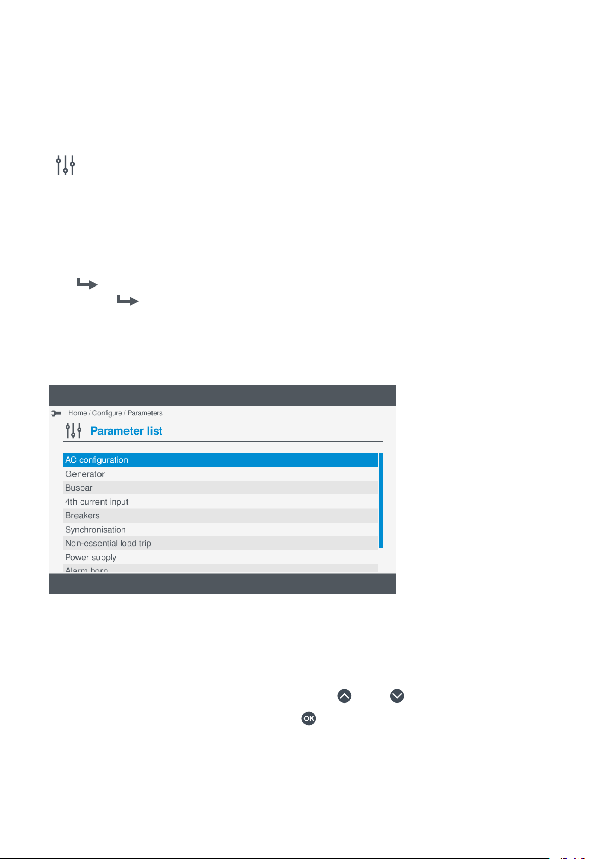
7.4 Parameters
Category
Group
Parameter(s)
PPM 300 Operator's manual 4189340910 UK
www.deif.com
Page 68 of 157
7.4.1 View or configure parameters
Configure parameter settings under Configure > Parameters.
You can configure the parameters for both system settings and alarm settings.
The parameters are organised into categories and groups:
Configure parameters
Figure 7.2
To configure the parameters, perform the following steps:
1. Select Configure , from the Home menu.
2. Select Parameters to view the controller parameter categories.
• The parameter categories shown depend upon the type of controller or whether the associated I/O has been
configured.
Example parameter categories
3. Highlight the parameter category you wish to open, by pressing Up or Down .
4. Select the highlighted parameter category by pressing OK
• The parameter groups under the selected category are shown on the display.
.
Page 69

5. Highlight the parameter group you wish to open, by pressing Up or Down .
Toggle
Write
Write
PPM 300 Operator's manual 4189340910 UK
6. Select the highlighted parameter group by pressing OK .
• The parameter settings are shown on the display.
7. To highlight the parameter, select Up or Down , by pressing .
8. To highlight the parameter settings, press Up or Down .
9. Change the setting, by pressing OK .
• If the setting can be toggled, you can use Toggle
, by pressing .
• If the setting is text or a value, pressing OK displays the virtual keyboard to alter the setting.
◦ The parameter settings minimum, maximum and default are also shown.
◦ Use the Virtual keyboard to make the required changes.
◦ To confirm the setting, select Write
, by pressing .
• If the setting is a selection, pressing OK displays an available list of selection options.
◦ Highlight the option required, by pressing Up
Select the option, by pressing OK
◦
.
◦ To confirm the setting, select Write
or Down .
, by pressing .
7.5 Input/output
7.5.1 Configure Input/output
Configure I/O settings under
Configure > Input/Output.
You can configure the I/O settings and terminals for any of the hardware modules within the connected controller.
See
Hardware characteristics, in the Designer's handbook for more information regarding the different
hardware modules and their terminal details.
To configure the I/O settings you need to perform the following steps:
1. Select hardware module to configure
2. Select terminal(s) to configure
3. Configure the terminal(s) settings
7.5.2 Selecting a hardware module
Before you can configure the I/O settings, you first need to select the hardware module in the controller.
www.deif.com Page 69 of 157
Page 70

INFO
PPM 300 Operator's manual 4189340910 UK
www.deif.com
Page 70 of 157
The hardware modules shown vary depending upon controller type or hardware modules installed. The hardware
selection screen shows the same hardware modules as you have installed in the controller.
Figure 7.3 Example select hardware module
INFO
Basic details about the available I/Os on the module are shown at the right.
Selecting a hardware module
To select the hardware module, perform the following steps:
1. To move between the hardware modules, select Left
• Basic information about the selected hardware module is shown at the right.
2. Select the highlighted hardware module by pressing OK .
• The I/O terminals for the hardware module are displayed on screen.
or Right , by pressing .
7.5.3 View or configure hardware module I/O terminals
After selecting the hardware module, the details of the available terminals are shown on the display.
Page 71

Figure 7.4 Example I/O configuration terminals
PPM 300 Operator's manual 4189340910 UK
If a terminal has already had configured for either a Function or Alarm, the terminal is marked with grey dot .
INFO
The actual terminal types shown depend upon the type of hardware module selected or installed.
Type Notes
DI Digital input
DO Digital output
AI Analogue input
AO Analogue output
PWM Pulse width modulation
View or configure terminal settings
1. Highlight the required terminal, by pressing Up or Down .
2. Select the highlighted terminal by pressing OK
• Details of the terminal settings are displayed on the screen.
.
7.5.4 I/O terminal settings
After selecting the hardware module and the required terminal, the details of the terminal settings are shown on the display.
www.deif.com Page 71 of 157
Page 72

Figure 7.5 Example hardware module terminals for a digital input (DI)
I/O name
Relay
Sensor
Output setup
Functions
Alarm
I/O name
PPM 300 Operator's manual 4189340910 UK
www.deif.com
Page 72 of 157
Here you can configure various settings for the terminal, subject to the type of terminal and hardware module selected.
INFO
The actual features you can select or configure are also subject to the type of hardware module you have selected.
Option Notes DI DO AI AO/PWM
Configure I/O name. ● ● ● ●
Configure relay. ●
Configure analogue input settings. ●
Configure analogue output or PWM settings. ●
Assign function(s) to the I/O. ● ● ● ●
Assign alarm(s) to the I/O. ● ● ● ●
7.6 Digital input (DI)
7.6.1 Configure I/O name
To rename the input or output name:
1. Select I/O name
• The virtual keyboard is displayed on screen to edit the I/O name.
.
Page 73

•
Write
Clear
Write
PPM 300 Operator's manual 4189340910 UK
2. Enter the required I/O name and select Write
7.6.2
The functions available are organised in to categories and groups, which is similar to a tree structure view.
Configure function(s)
.
Selecting a function
1. Highlight a category or group, by pressing Up or Down .
2. Select the highlighted category or group, by pressing OK .
• A further group may be shown or the function list to select the actual function.
• If a further group is shown, simply repeat step 1 to locate and open the required group.
Configure functions
1. To select the functions for the terminal:
• Highlight the required function, by pressing Up
• Enable the highlighted function, by pressing OK .
◦ Selected function(s) are shown with a solid box.
• To clear all the Enabled functions, select Clear
or Down .
.
• To save the setting(s) to the controller, select Write
◦ This only applies to the selected functions and does not apply other I/O change(s).
7.6.3 Configure alarm(s)
Create a new digital custom alarm
To create a new alarm, simply edit one of the available Digital custom alarms listed.
INFO
It is recommended to give your created alarms a new descriptive name for easier reference.
www.deif.com Page 73 of 157
.
Page 74

•
Edit
PPM 300 Operator's manual 4189340910 UK
www.deif.com
Page 74 of 157
1. Highlight a previously unused alarm, by pressing Up or Down .
Select the alarm by pressing OK
2.
.
• Selected alarm(s) are shown with a solid box.
3. Select Edit
.
• Details of the alarm settings are shown on the display for you to configure.
•
a. Highlight the required alarm setting, by pressing Up or Down .
b. To change the setting, press OK
◦ If the setting is Enable or Not enabled, pressing OK toggles either Enable or Not enabled.
◦ Enabled settings are marked with a solid box.
◦ If the setting is text or a value, pressing OK displays the virtual keyboard to alter the setting.
◦ Make the required changes using the virtual keyboard.
.
Page 75

◦ To confirm the changes, select Next
Next
Next
Write
Edit
PPM 300 Operator's manual 4189340910 UK
.
◦ If the setting is a selection, pressing OK displays an available list of selection options.
◦ Highlight the option required, by pressing Up or Down .
◦ Select or unselect the option, by pressing OK
◦ To confirm the setting, select Next
.
.
c. Once you have made all the required changes to the alarm settings, select Write
◦ This saves the alarm setting to the controller. This does not save any other settings.
◦ The list of available alarms is shown again on the display.
Select an existing digital custom alarm
You can use or edit an existing Digital custom alarm.
.
•
1. Highlight the required custom alarm, by pressing Up or Down .
CAUTION
Editing an existing custom alarm changes the alarm settings for ALL input terminals using the same alarm.
2. Select Edit
.
• Details of the alarm settings are shown on the display for you to configure.
www.deif.com Page 75 of 157
Page 76

•
Next
Next
Write
Write
Clear
Write
PPM 300 Operator's manual 4189340910 UK
www.deif.com
Page 76 of 157
a. Highlight the required alarm setting, by pressing Up or Down .
b. To change the setting, press OK .
◦ If the setting is Enable or Not enabled, pressing OK toggles either Enable or Not enabled.
◦ Enabled settings are marked with a solid box.
◦ If the setting is text or a value, pressing OK displays the virtual keyboard to alter the setting.
◦ Make the required changes using the virtual keyboard.
◦ To confirm the changes, select Next
.
◦ If the setting is a selection, pressing OK displays an available list of selection options.
◦ Highlight the option required, by pressing Up
or Down .
◦ Select or unselect the option, by pressing OK .
◦ To confirm the setting, select Next
c. Once you have made all the required changes to the alarm settings, select Write
.
.
◦ This saves the alarm setting to the controller. This does not save any other settings.
◦ The list of available alarms is shown again on the display.
3. To save the new setting to the controller, select Write
.
• This only saves the selected alarm(s) and their settings to the controller. It does not save other I/O settings.
Clear all enabled alarm(s)
1. To clear all the selected alarms, select Clear
2. To save the new setting to the controller, select Write
• This only saves the selected alarm(s) and their settings to the controller. It does not save other I/O settings.
.
.
Page 77

7.7 Digital output (DO)
I/O name
Write
PPM 300 Operator's manual 4189340910 UK
7.7.1 Configure I/O name
To rename the input or output name:
1. Select I/O name
• The virtual keyboard is displayed on screen to edit the I/O name.
•
2. Enter the required I/O name and select Write
.
7.7.2 View or configure I/O relay
.
You can configure the setting for the relay. The current configure state for the relay is shown on the display. By default all
relays are considered to be Normally open and in a De-energised state.
From this screen you can configure either a standard relay or a changeover relay, depending upon the type of relay that can
be connected to the hardware module terminals.
www.deif.com Page 77 of 157
Page 78

Figure 7.6 Example relay setup
Energise
De-energise
Write
PPM 300 Operator's manual 4189340910 UK
www.deif.com
Page 78 of 157
See Hardware characteristics, in the Designer's handbook for more information about the hardware modules that
support relays.
Configure the relay
1. You can set the relay as either Energise or De-energise.
• The current setting is shown on the display.
2. You can set the relay as either Energise or De-energise.
3. To set as Energise select Energise
4. To set as De-energise select De-energise
5. To save the setting to the controller, select Write
, by pressing .
, by pressing the appropriate push-button .
, by pressing .
• You are returned to the terminal screen.
7.7.3 Configure function(s)
The functions available are organised in to categories and groups, which is similar to a tree structure view.
Selecting a function
1. Highlight a category or group, by pressing Up
2. Select the highlighted category or group, by pressing OK .
• A further group may be shown or the function list to select the actual function.
• If a further group is shown, simply repeat step 1 to locate and open the required group.
or Down .
Page 79

Configure functions
Clear
Write
PPM 300 Operator's manual 4189340910 UK
1. To select the functions for the terminal:
• Highlight the required function, by pressing Up or Down .
• Enable the highlighted function, by pressing OK .
◦ Selected function(s) are shown with a solid box.
• To clear all the Enabled functions, select Clear
• To save the setting(s) to the controller, select Write
.
.
◦ This only applies to the selected functions and does not apply other I/O change(s).
7.7.4 Configure alarms
The alarms available for a digital output (DO) are organised in to categories and groups, which are similar to a tree structure
view.
INFO
When viewing or configuring a previously configured I/O with an alarm, the display will automatically jump to the
alarm settings. You can, if required, use Back to return to the alarm selection screen.
Selecting an alarm
1. Highlight a category or group, by pressing Up or Down .
2. Select the highlighted category or group, by pressing OK
• A further group may be shown or the alarm list to select the actual alarm(s).
• If a further group is shown, simply repeat step 1 to locate and open the required group.
3. Highlight the required alarm, by pressing Up or Down .
• Details of the alarm settings are shown at the right side of the display.
www.deif.com Page 79 of 157
.
Page 80

•
Write
Clear
Write
PPM 300 Operator's manual 4189340910 UK
www.deif.com
Page 80 of 157
INFO
These settings cannot be configured here and must be configured in the Parameters page.
4. Select the alarm, by pressing OK .
• The selected alarm is shown with a solid box.
• To remove the selection, press OK again.
5. To save the settings to the controller, select Write
.
• This only saves the selected alarm(s) and their settings to the controller. It does not save other I/O settings.
Clear all enabled alarm(s)
1. To clear all the selected alarms, select Clear
2. To save the new setting to the controller, select Write
• This only saves the selected alarm(s) and their settings to the controller. It does not save other I/O settings.
.
.
7.8 Analogue input (AI)
7.8.1
You can use an analogue input for the following:
• As an input for one or more controller analogue functions.
• As a supervised input for one or more controller digital functions.
• To detect sensor failure.
• As the basis for one or more alarms.
Introduction to analogue inputs
For each analogue input use, the table below shows which pages in the analogue input view you must configure.
Page 81

Table 7.1 Configuration for the uses of an analogue input
I/O name
PPM 300 Operator's manual 4189340910 UK
Use Functions* Sensor setup* Alarms*
Analogue function(s) ● ● ○
Digital function(s) ● ● ○
Sensor failure ○ ● ○
Alarm(s) ○ ● ●
*Note: ● represents required configuration. ○ represents optional configuration.
7.8.2 Configure Analogue input (AI)
To configure the analogue input (AI) you need to do the following:
1. Select the hardware module, terminal(s), for an Analogue input (AI) to be used.
• Optional: You can configure the I/O name.
• See Analogue input (AI), Configure I/O name.
2. If required, select the input function(s) (y-axis).
• These can be either Analogue function(s) or Supervised binary input function(s).
See Analogue input (AI), Configure function(s) for how to select the function(s).
•
3. Configure the Sensor settings and curve (x-axis).
• You can use a predefined curve or reuse/configure a custom curve.
• See Analogue input (AI), View or configure Sensor for how to configure the Sensor curve.
4. If required, configure custom alarm(s).
• See Analogue input (AI), Configure alarm(s) for how to configure the alarm(s).
As you complete each configuration, write the settings to the controller.
7.8.3 Configure I/O name
To rename the input or output name:
1. Select I/O name
• The virtual keyboard is displayed on screen to edit the I/O name.
.
www.deif.com Page 81 of 157
Page 82

•
Write
PPM 300 Operator's manual 4189340910 UK
www.deif.com
Page 82 of 157
2. Enter the required I/O name and select Write
7.8.4
Configure function(s)
.
The functions available are organised in to categories and groups, which are similar to a tree structure view.
For analogue inputs (AI) you can select either:
• Analog: Analogue function(s)
• Digital: Supervised binary input function(s)
CAUTION
When using Supervised binary input function(s) you must configure the curve with y minimum 0 and y maximum 1
before selecting the binary function(s).
Selecting a function
Page 83

1. For digital function(s), select Digital
Digital
Analogue
Clear
Write
PPM 300 Operator's manual 4189340910 UK
.
2. For analogue function(s), select Analog
.
INFO
Analogue function(s) are shown by default when you open the page.
3. Highlight a category or group, by pressing Up or Down .
4. Select the highlighted category or group, by pressing OK .
• The display unit will show the function list, or another function group.
• If another function group is shown, repeat step 3 to open the required group.
5. Highlight a function, by pressing Up or Down .
6. Enable the highlighted function, by pressing OK .
• Selected function(s) are shown with a solid box.
•
INFO
You can add further functions to the same input, provided they have the same unit of measure.
7. To clear all the Enabled function(s), select Clear
8. To save the settings to the controller, select Write
.
.
INFO
This only applies to the selected functions and does not apply other I/O change(s).
www.deif.com Page 83 of 157
Page 84

9. The enabled function(s) are now shown on the screen:
Clear
Write
PPM 300 Operator's manual 4189340910 UK
www.deif.com
Page 84 of 157
•
Edit a function or clear function(s)
1. You can edit the selected function(s), by pressing OK .
• The function is now shown on the screen:
•
¨
2. To clear all the Enabled function(s), select Clear
3. To save the settings to the controller, select Write
INFO
This only applies to the selected functions and does not apply other I/O change(s).
• The terminal(s) settings are now shown on the screen.
.
.
Page 85

7.8.5
Edit
PPM 300 Operator's manual 4189340910 UK
Configure alarm(s)
Create a new analogue custom alarm
To create a new alarm, edit one of the available Analogue custom alarms listed.
INFO
Give the alarm a descriptive name, for easier reference.
•
1. Highlight a previously unused alarm, by pressing Up or Down .
2. Select and enable the alarm by pressing OK
• Enabled alarm(s) are shown with a solid box.
3. Select Edit
• Details of the alarm settings are shown on the display for you to configure.
.
.
www.deif.com Page 85 of 157
Page 86

•
Next
Next
Write
PPM 300 Operator's manual 4189340910 UK
www.deif.com
Page 86 of 157
a. Highlight the required alarm setting, by pressing Up or Down .
b. To change the setting, press OK .
◦ If the setting is Enable or Not enabled, pressing OK toggles either Enable or Not enabled.
◦ Enabled settings are marked with a solid box.
◦ If the setting is text or a value, pressing OK displays the virtual keyboard to alter the setting.
◦ Make the required changes using the virtual keyboard.
◦ To confirm the changes, select Next
.
◦ If the setting is a selection, pressing OK displays an available list of selection options.
◦ Highlight the option required, by pressing Up
or Down .
◦ Select or unselect the option, by pressing OK .
◦ To confirm the setting, select Next
.
c. Once you have made all the required changes to the alarm settings, select Write
◦ This saves the alarm setting to the controller. This does not save any other settings.
◦ The list of available alarms is shown again on the display.
Select an existing analogue custom alarm
You can use or edit an existing Analogue custom alarm.
.
Page 87

•
Edit
Next
PPM 300 Operator's manual 4189340910 UK
1. Highlight the required custom alarm, by pressing Up or Down .
Select Edit
2.
.
• Details of the alarm settings are shown on the display for you to configure.
•
a. Highlight the required alarm setting, by pressing Up or Down .
b. To change the setting, press OK .
◦ If the setting is Enable or Not enabled, pressing OK toggles either Enable or Not enabled.
◦ Enabled settings are marked with a solid box.
◦ If the setting is text or a value, pressing OK displays the virtual keyboard to alter the setting.
◦ Make the required changes using the virtual keyboard.
◦ To confirm the changes, select Next
www.deif.com Page 87 of 157
.
Page 88

◦ If the setting is a selection, pressing OK displays an available list of selection options.
Next
Write
Write
Clear
Write
Sensor
PPM 300 Operator's manual 4189340910 UK
www.deif.com
Page 88 of 157
◦ Highlight the option required, by pressing Up or Down .
◦ Select or unselect the option, by pressing OK .
◦ To confirm the setting, select Next
c. Once you have made all the required changes to the alarm settings, select Write
.
.
◦ This saves the alarm setting to the controller. This does not save any other settings.
◦ The list of available alarms is shown again on the display.
3. To save the new setting to the controller, select Write
.
• This only saves the selected alarm(s) and their settings to the controller. It does not save other I/O settings.
Clear all enabled alarm(s)
1. To clear all the selected alarms, select Clear
2. To save the new setting to the controller, select Write
• This only saves the selected alarm(s) and their settings to the controller. It does not save other I/O settings.
.
.
7.8.6 View or configure sensor
INFO
Configure any required function(s) before configuring the sensor settings.
See Analogue input (AI), Configure function(s) for more information.
Configure the Sensor
1. To configure the Sensor, select Sensor
• A list of available output types are shown on the display.
•
.
Page 89

INFO
Next
PPM 300 Operator's manual 4189340910 UK
This is the x-axis.
2. Highlight the required output type, by pressing Up or Down .
3. Select the highlighted output type, by pressing OK
• The selected output type is marked with a solid box.
•
4. To proceed to the next stage, select Next
.
.
•
You can now choose to do one of the following:
• Select a pre-configured curve.
• Select a new custom curve.
• Select or edit an existing custom curve.
www.deif.com Page 89 of 157
Page 90

CAUTION
PPM 300 Operator's manual 4189340910 UK
www.deif.com
Page 90 of 157
You can reuse any previously created custom curve on any terminal(s). However, the configuration settings are the
same across all the other I/O terminals. If you alter the settings for a curve this will apply to all other I/O terminals
where the curve has been used.
Select a pre-configured curve
INFO
If available, you can select a pre-configured curve, for example VDO 5. Details for the curve are shown on the right
and you cannot modify a pre-configured curve.
1. Highlight the pre-configured curve, by pressing Up or Down .
2. Select the pre-configured curve, by pressing OK .
• The selected curve is shown with a solid box.
•
• To remove the selection, press OK again.
Page 91

3. To save the settings to the controller, select Write
Write
Edit
PPM 300 Operator's manual 4189340910 UK
.
• This only saves the selected settings to the controller. It does not save other I/O settings.
Select a new custom curve
1. Highlight an unused custom curve, by pressing Up or Down .
•
2. Select Edit
.
• Details of the curve settings are shown on the display:
www.deif.com Page 91 of 157
Page 92

•
Next
PPM 300 Operator's manual 4189340910 UK
www.deif.com
Page 92 of 157
3. Highlight a curve setting, by pressing Up or Down .
4. Edit the highlighted setting, by pressing OK .
• If the setting is text or a value, pressing OK displays the virtual keyboard to change the setting.
◦ For example, the name of the curve:
◦
◦ To confirm the setting, select Next
• If the setting is a selection, pressing OK displays an available list of selection options.
◦ For example, the y-axis units:
.
Page 93

◦
Next
Add
PPM 300 Operator's manual 4189340910 UK
◦ Highlight the option required, by pressing Up or Down .
◦ Select or un-select the option, by pressing OK .
To confirm the setting, select Next
◦
.
• If the setting is the x,y coordinates, pressing OK displays the coordinate options.
◦
CAUTION
Configure the y-axis units, y-axis minimum, and y-axis maximum BEFORE attempting to configure the
x,y coordinates.
CAUTION
A valid curve must contain a minimum of 2 sets of coordinates.
a. Add coordinates:
a. To add a set of x,y coordinates, select Add
◦ The Virtual keyboard is shown on the display:
www.deif.com Page 93 of 157
.
Page 94

◦
Next
PPM 300 Operator's manual 4189340910 UK
www.deif.com
Page 94 of 157
b. Enter the x-axis coordinate using the Virtual keyboard:
◦ This must be between the minimum and maximum values shown:
◦
◦ Select Next
.
c. Enter the y-axis coordinate using the Virtual keyboard:
◦ This must be between the minimum and maximum values shown:
Page 95
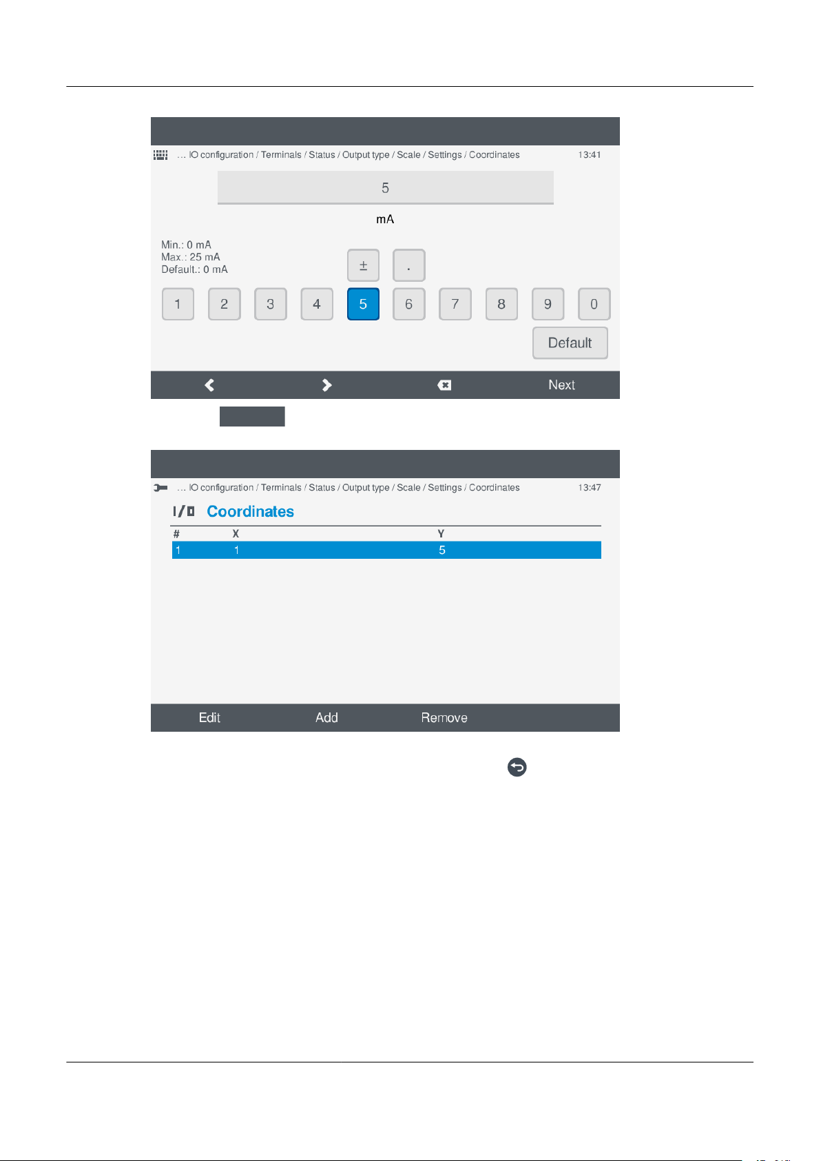
◦
Next
PPM 300 Operator's manual 4189340910 UK
◦ Select Next
.
d. The x,y coordinates are added to the list:
◦
e. You can add a maximum of 30 coordinates to the curve.
f. When you have added all the coordinates you require, press Back to return to the curve settings.
www.deif.com Page 95 of 157
Page 96
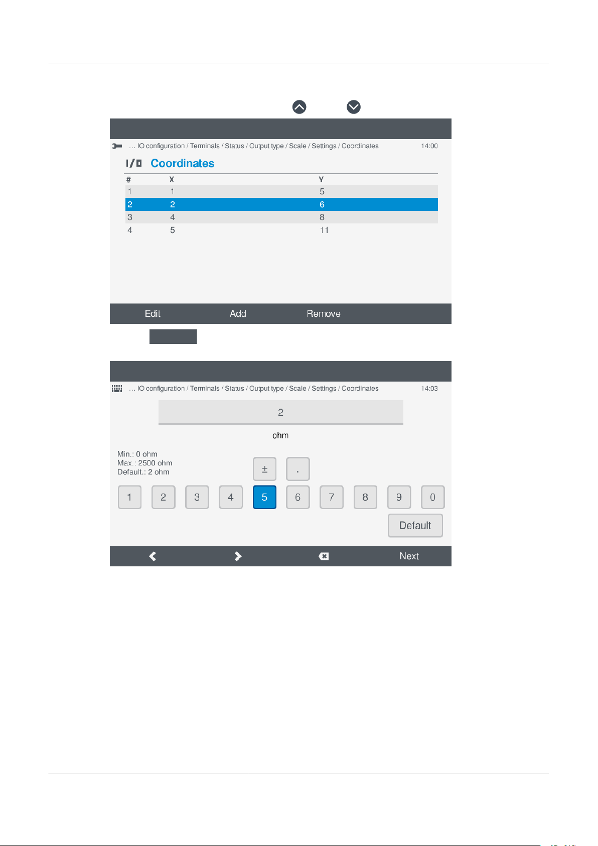
b. Edit coordinates:
Edit
PPM 300 Operator's manual 4189340910 UK
www.deif.com
Page 96 of 157
a. Highlight the coordinate to edit, by pressing Up
or Down .
◦
b. Select Edit
.
◦ The Virtual keyboard is shown on the display for the x coordinate.
◦
Page 97

c. Edit the x coordinate using the Virtual keyboard:
Next
Next
PPM 300 Operator's manual 4189340910 UK
◦
◦ Select Next
.
d. Edit the y coordinate using the Virtual keyboard:
◦
◦ Select Next
.
www.deif.com Page 97 of 157
Page 98

e. The x,y coordinates are updated in the list:
Remove
PPM 300 Operator's manual 4189340910 UK
www.deif.com
Page 98 of 157
◦
f. When you have added/edited all the coordinates you require, press Back to return to the curve settings.
c. Remove coordinates:
a. Highlight the coordinate to remove, by pressing Up
◦
b. Select Remove
.
◦ The coordinate is removed from the coordinate list:
or Down .
Page 99

◦
Write
PPM 300 Operator's manual 4189340910 UK
5. When you have added/edited all the coordinates you require, press Back to return to the curve settings.
•
6. To save the curve to the controller, select Write
.
• The custom curve is updated in the list:
www.deif.com Page 99 of 157
Page 100

•
Write
PPM 300 Operator's manual 4189340910 UK
www.deif.com
Page 100 of 157
7. Highlight the custom curve, by pressing Up or Down .
8. Select the custom curve, pressing OK :
• The selected custom curve is marked with a solid box.
•
9. To save the settings to the controller, select Write
• You are returned to the terminals page.
7.9 Analogue output (AO) / Pulse width modulation (PWM)
7.9.1 Configure Analogue output (AO)
To configure the analogue output (AO):
1. Select the hardware module, terminal(s), for an Analogue output (AO) to be used.
2. If required, select the function input (x-axis).
.
 Loading...