

Page 1
DEIF A/S · Frisenborgvej 33 · DK-7800 Skive · Tel.: +45 9614 9614 · Fax: +45 9614 9615 · info@deif.com · www.deif.com
DESIGNER'S REFERENCE HANDBOOK
Multi Differential Relay, MDR-2
● Differential current protection,
generator or electric motor
Document no.: 4189340300I
SW version:
Page 2

1. General information
1.1. Warnings, legal information and safety.................................................................................................. 4
1.1.1. Warnings and notes ......................................................................................................................4
1.1.2. Legal information and disclaimer ..................................................................................................4
1.1.3. Safety issues ................................................................................................................................ 4
1.1.4. Electrostatic discharge awareness ............................................................................................... 4
1.1.5. Factory settings ............................................................................................................................ 5
1.2. About the Designer's Reference Handbook........................................................................................... 5
1.2.1. General purpose ...........................................................................................................................5
1.2.2. Intended users ..............................................................................................................................5
1.2.3. Contents and overall structure ......................................................................................................5
2. Preface
2.1. General data...........................................................................................................................................6
2.1.1. Technical specifications ................................................................................................................ 6
3. Standard functions
3.1. Differential current detection.................................................................................................................. 7
3.1.1. Differential current tripping/warning ..............................................................................................8
3.2. Display....................................................................................................................................................8
3.2.1. Panel cutout for display .............................................................................................................. 10
3.2.2. Unit dimensions in mm (inches)...................................................................................................11
4. Hardware
4.1. Terminals and board slot positions....................................................................................................... 12
4.2. Base unit LED indicators...................................................................................................................... 12
4.3. Terminal strip overview.........................................................................................................................14
4.3.1. Slots #1, #2, #5 and #6 ...............................................................................................................14
4.3.2. Slots #3, #4, #7 and #8 ...............................................................................................................15
4.4. Terminal strip, explanation....................................................................................................................15
4.4.1. Slot #1, power supply and digital I/O .......................................................................................... 16
4.4.2. Slot #7, AC current measurement .............................................................................................. 17
5. Wiring diagrams
5.1. Coupling and connection......................................................................................................................18
5.1.1. AC current measurements, star coupling.................................................................................... 18
5.1.2. AC current measurements, delta coupling ..................................................................................19
5.1.3. DC connections, inputs and outputs ...........................................................................................20
6. Parameter programming
6.1. Programming........................................................................................................................................21
6.1.1. About programming..................................................................................................................... 21
6.1.2. Parameter setting method in display .......................................................................................... 21
6.2. Differential current................................................................................................................................21
6.2.1. Settings .......................................................................................................................................21
6.2.2. Warning (curve 1) ....................................................................................................................... 22
6.2.3. Trip (curve 2) .............................................................................................................................. 22
6.2.4. Trip (fixed trip value) ...................................................................................................................23
6.2.5. Use of relay outputs ....................................................................................................................23
6.3. Other settings.......................................................................................................................................23
6.3.1. Status LED ..................................................................................................................................23
6.3.2. Auto acknowledgement of alarms ...............................................................................................23
6.3.3. Service menu ..............................................................................................................................24
6.4. Nominal settings...................................................................................................................................24
6.4.1. Nominal current .......................................................................................................................... 24
6.4.2. Current transformers ...................................................................................................................24
6.4.3. Date and time (internal clock) .....................................................................................................25
6.4.4. Power supply (battery) under-voltage alarm ...............................................................................25
MDR-2 DRH 4189340300 UK
DEIF A/S Page 2 of 26
Page 3

6.4.5. User password for programming via display................................................................................25
6.4.6. Language selection .....................................................................................................................26
MDR-2 DRH 4189340300 UK
DEIF A/S Page 3 of 26
Page 4
1. General information
1.1 Warnings, legal information and safety
1.1.1 Warnings and notes
Throughout this document, a number of warnings and notes with helpful user information will be presented.
To ensure that these are noticed, they will be highlighted as follows in order to separate them from the general text.
Warnings
Warnings indicate a potentially dangerous situation, which could result in death, personal injury or damaged equipment, if certain guidelines are not followed.
Notes
Notes provide general information, which will be helpful for the reader to bear in mind.
1.1.2 Legal information and disclaimer
DEIF takes no responsibility for installation or operation of the generator set. If there is any doubt about how
to install or operate the engine/generator controlled by the Multi-line 2 unit, the company responsible for the
installation or the operation of the set must be contacted.
The Multi-line 2 unit is not to be opened by unauthorised personnel. If opened anyway, the warranty will be lost.
Disclaimer
DEIF A/S reserves the right to change any of the contents of this document without prior notice.
The English version of this document always contains the most recent and up-to-date information about the
product. DEIF does not take responsibility for the accuracy of translations, and translations might not be updated at the same time as the English document. If there is a discrepancy, the English version prevails.
1.1.3 Safety issues
Installing and operating the Multi-line 2 unit may imply work with dangerous currents and voltages. Therefore,
the installation should only be carried out by authorised personnel who understand the risks involved in working with live electrical equipment.
Be aware of the hazardous live currents and voltages. Do not touch any AC measurement inputs as this could lead to injury or death.
1.1.4 Electrostatic discharge awareness
Sufficient care must be taken to protect the terminal against static discharges during the installation. Once the
unit is installed and connected, these precautions are no longer necessary.
MDR-2 DRH 4189340300 UK
General information
DEIF A/S Page 4 of 26
Page 5

1.1.5 Factory settings
The Multi-line 2 unit is delivered from factory with certain factory settings. These are based on average values
and are not necessarily the correct settings for matching the engine/generator set in question. Precautions
must be taken to check the settings before running the engine/generator set.
1.2 About the Designer's Reference Handbook
1.2.1 General purpose
This Designer's Reference Handbook mainly includes functional descriptions, presentation of display unit and
menu structure, information about the PID controller, the procedure for parameter setup and reference to parameter lists.
The general purpose of this document is to provide useful overall information about the functionality of the
unit and its applications. This document also offers the user the information he needs in order to successfully
set up the parameters needed in his specific application.
Please make sure to read this document before starting to work with the Multi-line 2 unit and
the genset to be controlled. Failure to do this could result in human injury or damage to the
equipment.
1.2.2 Intended users
This Designer's Reference Handbook is mainly intended for the panel builder designer in charge. On the basis of this document, the panel builder designer will give the electrician the information he needs in order to
install the Multi-line 2 unit, for example detailed electrical drawings. In some cases, the electrician may use
these installation instructions himself.
1.2.3 Contents and overall structure
This document is divided into chapters, and in order to make the structure simple and easy to use, each
chapter will begin from the top of a new page.
MDR-2 DRH 4189340300 UK General information
DEIF A/S Page 5 of 26
Page 6
2. Preface
2.1 General data
2.1.1 Technical specifications
Accuracy 0.1 × IN < I < IN: 1 % of IN
IN < I: 1 % of I
(IN = 1 A or 5 A, I = measured value, secondary side of CT)
Operating temperature
-25 to 70 °C
Aux. supply 12/24 V DC nominal (8 to 36 V DC operational), max. 11 W consumption
0 V DC for 10 ms when coming from at least 24 V DC
Frequency 30 to 70 Hz
Measuring current From current transformers …/1 A or …/5 A. Consumption max. 0.3 VA per phase.
Digital inputs Input voltage 6 to 32 V DC. Impedance 2.4 kΩ, bi-directional.
Relay outputs 250 V/8 A or 24 V DC/1 A. Refer to actual description of I/Os.
Safety To EN 61010-1 installation category (over-voltage category) III, 600 V, pollution de-
gree 2
Galvanic separation
Between AC current and other I/Os: 3250 V AC – 50 Hz – 1 min.
EMC/CE According to EN-61000-1/2/3/4 IEC 255-3
Material All plastic parts are self-extinguishing to UL94 (V1)
Climate HSE, to DIN 40040
Connections
AC currents: 4 mm2 multi-stranded
Others: 2.5 mm2 multi-stranded
Display: 9-pin SUB-D female
Service port: 9-pin SUB-D male
Response times Response times are measured from end of period of measured current cycle
Differential current: <50 ms
Protection Case: IP40
Terminals: IP20
Operator panel (option): IP40 (IP54 when mounted with gasket)
To IEC 529 and EM 60529
Mounting Base-mounted with six screws or DIN-rail mounted
Weight Approx. 1 kg incl. packing
MDR-2 DRH 4189340300 UK Preface
DEIF A/S Page 6 of 26
Page 7

3. Standard functions
3.1 Differential current detection
The MDR-2 is primarily intended for protection of a generator or an electric motor against current leaks. This
is accomplished by measuring the current on each side of the generator/motor and comparing these. If there
is a difference (differential current), a leak is detected.
The differential current detection takes place in each phase.
So, the differential current detection is based on:
Primary side
(I1)
Secondary side
(I2)
L1 compared to L1
L2 compared to L2
L3 compared to L3
MDR-2
Generator/Motor
Step up transformer
(option C4)
MDR-2 DRH 4189340300 UK Standard functions
DEIF A/S Page 7 of 26
Page 8

3.1.1 Differential current tripping/warning
The pickup characteristics are defined using customisable curves.
100% 200% 300% 400% 500%
Trip at fixed value 100%
Trip at fixed value 85%
Upper limit
Lower limit
Trip Y1T
Warn. Y1W
Trip Y2T
Warn. Y2W
SP-X1
0%
50%
100%
Adjustable warning curve
Adjustable trip curve
Id
In
Is
In
The trip/warning pickup characteristics are shown above. They are a function of:
● Stabilisation current Is in relation to nominal current In (X-axis)
● Differential current Id in relation to nominal current In (Y-axis)
The lines marked "UPPER LIMIT" and "LOWER LIMIT" are the limits for the curves.
Max. values are:
● X1: 500 %
● Y1: 45 %
● Y2: 95 %
Min. values are:
● X1: 50 %
● Y1: 5 %
● Y2: 25 %
There are two sets of adjustable settings:
● Warning, set points Y1W and Y2W (can be disabled)
● Trip, set points SP-X1, Y1T and Y2T
The warning curve shares the SP-X1 value with the trip curve.
Both settings are with adjustable time delay (0.01 to 2.00 sec.)
3.2 Display
Front-mounted display with push-buttons and display of all measured values and alarms.
The following values can be read:
MDR-2 DRH 4189340300 UK
Standard functions
DEIF A/S Page 8 of 26
Page 9

● Phase currents L1, L2, L3 primary side (I1)
● Phase currents L1, L2, L3 secondary side (I2)
● Phase currents are presented in actual current and % of nominal value
● Differential currents are presented in actual current and % of nominal value
● Stabilisation currents (average of I1 and I2 values, displayed for each phase)
The alarm and event log list can be read.
All parameter settings can be made via the display.
Alarm
Alarm
INFO
JUMP
Multi Differential Relay
multi-line MDR
Power
Self check ok
Alarm Inh.
VIEW
LOG
BACK
SEL
389A 389A 389A
PROT SETUP
PROT
Fail
Comm.
The push-buttons are:
INFO: Displays the alarm list. If no active alarms are present, the list will be empty.
JUMP: Enables the user to jump directly to a specific setting instead of entering via the menu system.
VIEW: Scrolls the readings in the upper line of the display (in the protection setting menu).
LOG: Enters the log list. The log list contains max. 150 historical events/alarms, all with time and date.
SEL: Selects the chosen menu/value (enter function).
Up/down value buttons. Used for changing of settings, and so on.
Move buttons. Moves the cursor (in the lower line of the display) during manoeuvring in the menus.
MDR-2 DRH 4189340300 UK Standard functions
DEIF A/S Page 9 of 26
Page 10

3.2.1 Panel cutout for display
61.0 24.0
24.0 66.0
113.0
174.0
33.030.0
33.0
10.0
6x Ø4.5
Required space 220x115 mm
Gasket outer 183x77 mm
Screws for fastening:
3.5 mm self-cutting threads.
Max depth in display 9 mm
MDR-2 DRH 4189340300 UK Standard functions
DEIF A/S Page 10 of 26
Page 11
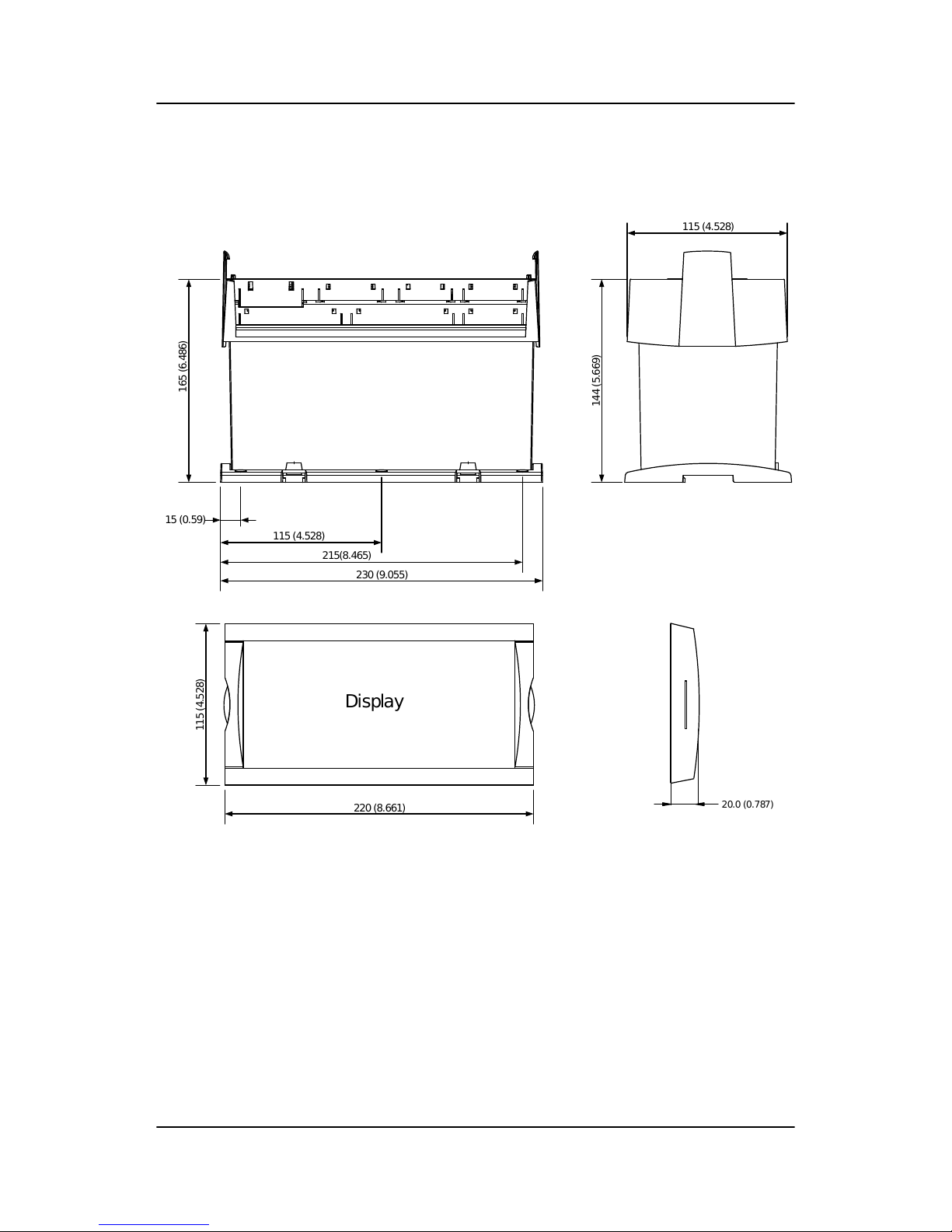
3.2.2 Unit dimensions in mm (inches)
Display
20.0 (0.787)
230 (9.055)
215(8.465)
115 (4.528)
15 (0.59)
165 (6.486)
115 (4.528)
144 (5.669)
220 (8.661)
115 (4.528)
MDR-2 DRH 4189340300 UK Standard functions
DEIF A/S Page 11 of 26
Page 12

4. Hardware
4.1 Terminals and board slot positions
The Multi-line 2 housing is divided into board slot positions, some of which are standard (non-changeable)
and some intended for options. The MDR-2 unit is divided like this:
Slot Slot type Terminal MDR-2
Slot #1 Power supply and digital I/O 1-28 Standard
Slot #2 Not used 29-36
Slot #3 Not used 37-64
Slot #4 Not used 65-72
Slot #5 Not used 84-89
Slot #6 Not used 90-97
Slot #7 AC current measurement 98-109 Standard
Slot #8 Not used 126-133
An overview of the terminals can be seen below. The slots are positioned in the unit as follows (seen from the
top of the unit):
I>> I> Id
R1 R2 R3 R4
Sevice port Display
1
2
3 4
5
6
7
8
4.2 Base unit LED indicators
There are 11 LED indicators on the front of the base unit. The indications are:
Power: DC power is on
Self check OK: The microprocessor watchdog status is OK. This relates to the "Status" relay output (nor-
mally energised)
Comm.: Communication status: not used
I>>: Option: short-circuit trip indication
I>: Option: over-current trip indication
MDR-2 DRH 4189340300 UK Hardware
DEIF A/S Page 12 of 26
Page 13

Id: There are two LEDs. The left one is differential current warning, the right one is differential
current trip
R1, R2, R3, R4: Green by deactivated relay output, red by activated relay output
NOTE:
I>> and I> share the same LEDs.
I>>, I> and Id LEDs are turned off if the function is not chosen or inhibited.
I>>, I> and Id LEDs can indicate status (yellow light) if the function is turned ON. Refer to the paragraph "Status LED".
MDR-2 DRH 4189340300 UK Hardware
DEIF A/S Page 13 of 26
Page 14

4.3 Terminal strip overview
4.3.1 Slots #1, #2, #5 and #6
MDR-2 DRH 4189340300 UK Hardware
DEIF A/S Page 14 of 26
Page 15
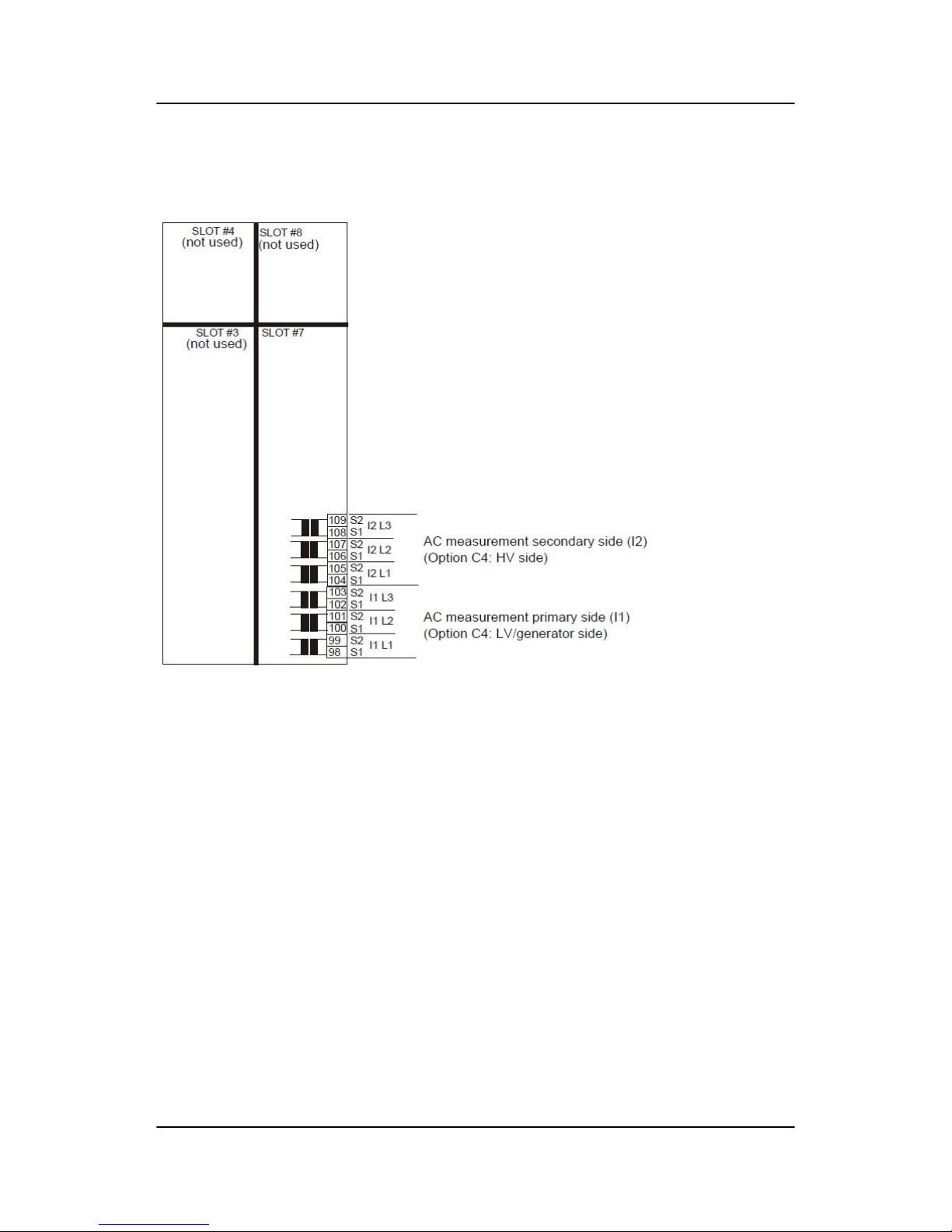
4.3.2 Slots #3, #4, #7 and #8
4.4 Terminal strip, explanation
For the relay outputs, the following terms will be used:
NO means Normally Open
NC means Normally Closed
Com. means common terminal for the relay in question
MDR-2 DRH 4189340300 UK Hardware
DEIF A/S Page 15 of 26
Page 16
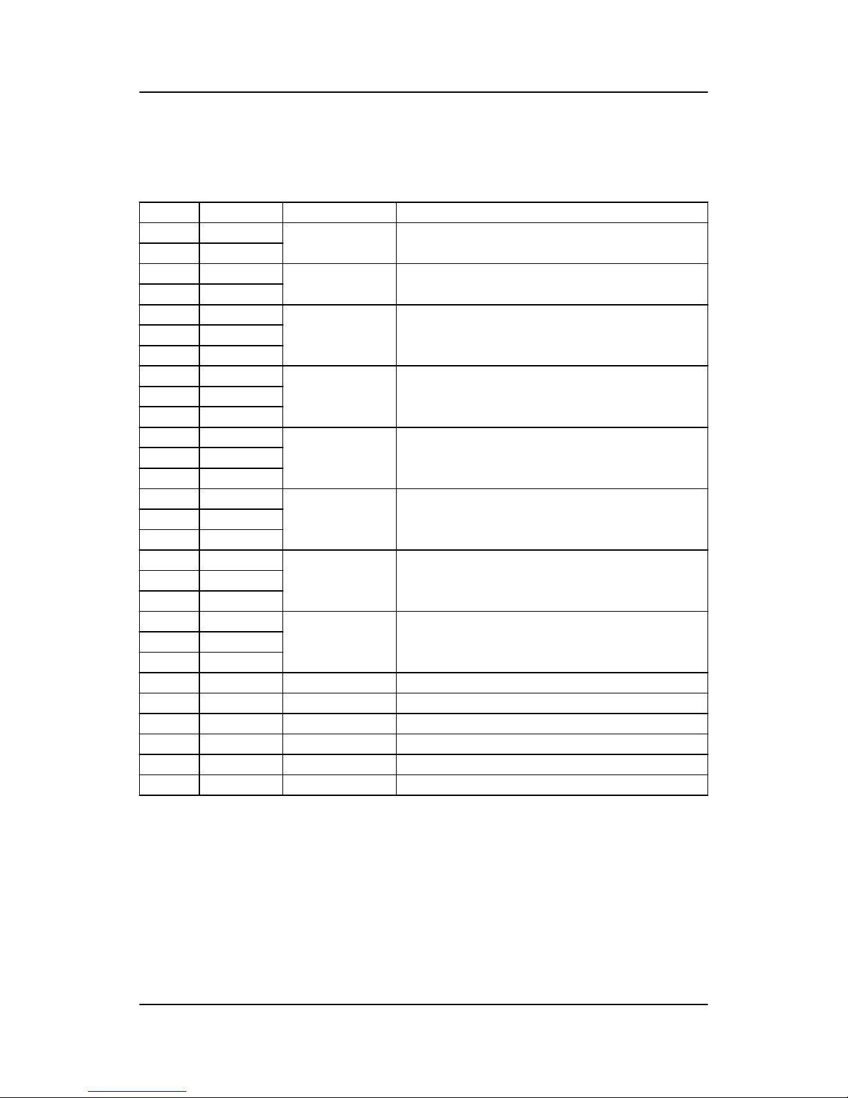
4.4.1 Slot #1, power supply and digital I/O
Standard board (always needed)
Terminal Function Technical data Description
1 +24 V DC 24 V DC +20/-30 % Power supply
2 0 V DC
3 NC Status relay
24 V DC/1 A
Normally closed relay, processor/power supply status supervision
4 Com.
5 NO Relay 1
250 V AC/8 A
Configurable relay
6 Com.
7 NC
8 NO Relay 2
250 V AC/8 A
Configurable relay
9 Com.
10 NC
11 NO Relay 3
250 V AC/8 A
Configurable relay
12 Com.
13 NC
14 NO Relay 4
250 V AC/8 A
Configurable relay
15 Com.
16 NC
17 NO Relay 5
250 V AC/8 A
Configurable relay
18 Com.
19 NC
20 Not used
21
22
23 Digital input 1 Optocoupler Id trip inhibit (differential current trip inhibit)
24 Digital input 2 Optocoupler Alarm acknowledge
25 Digital input 3 Optocoupler
26 Digital input 4 Optocoupler
27 Digital input 5 Optocoupler
28 Com. Common Common for terminals 23 to 27
MDR-2 DRH 4189340300 UK Hardware
DEIF A/S Page 16 of 26
Page 17
4.4.2 Slot #7, AC current measurement
Terminal Function Technical data Description
98 S1 (k) I 1L1 Primary side current measurements (I1)
99 S2 (l)
100 S1 (k) I 1L2
101 S2 (l)
102 S1 (k) I 1L3
103 S2 (l)
104 S1 (k) I 2L1 Secondary side current measurements (I2)
105 S2 (l)
106 S1 (k) I 2L2
107 S2 (l)
108 S1 (k) I 2L3
109 S2 (l)
MDR-2 DRH 4189340300 UK Hardware
DEIF A/S Page 17 of 26
Page 18
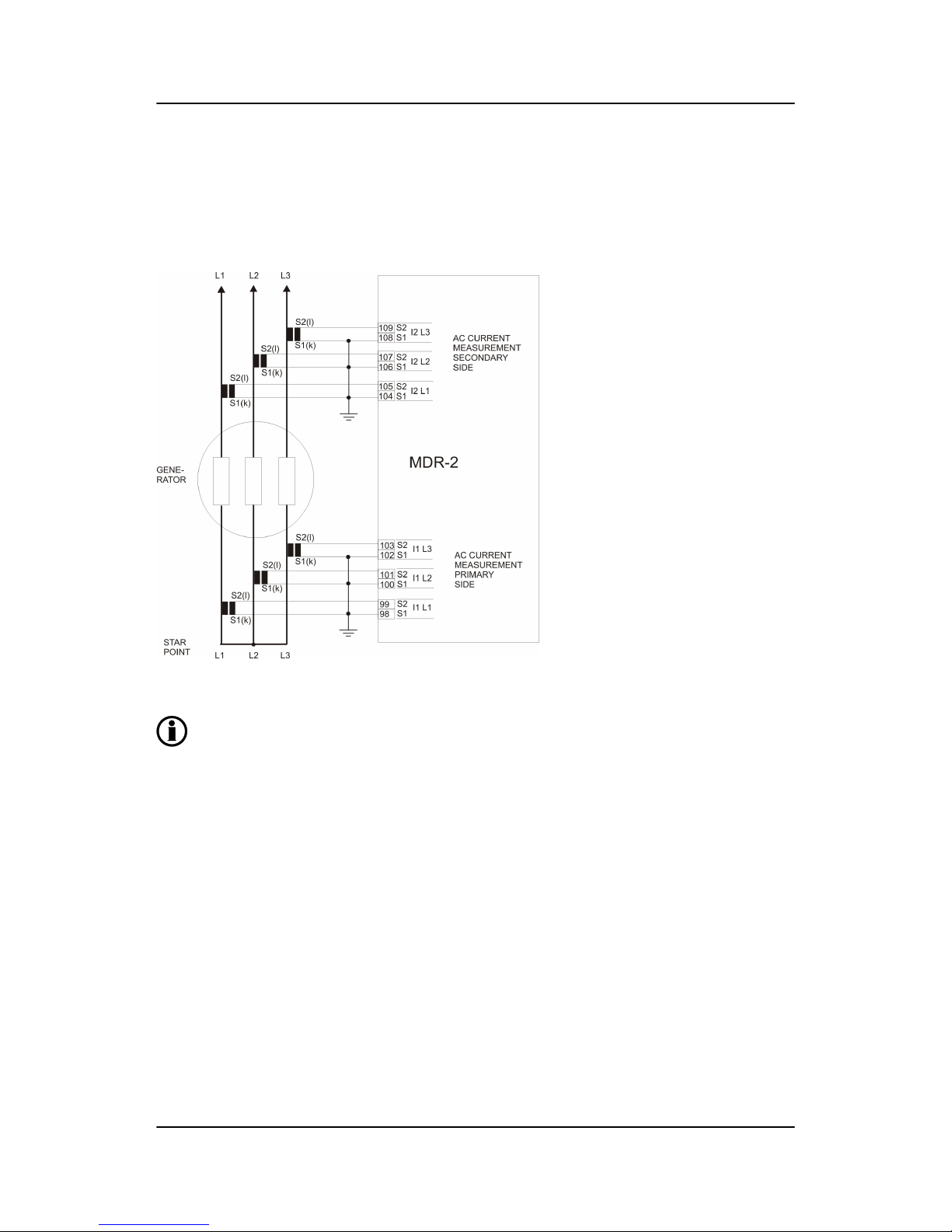
5. Wiring diagrams
5.1 Coupling and connection
5.1.1 AC current measurements, star coupling
The ground connections can be connected to S1 or S2 as needed.
MDR-2 DRH 4189340300 UK Wiring diagrams
DEIF A/S Page 18 of 26
Page 19

5.1.2 AC current measurements, delta coupling
MDR-2
S2(l)
S1(k)
AC current
measurement
primary side (I1)
AC current
measurement
secondary side (I2)
L1
L2 L3
109
108
I2 L3
S2
S1
107
106
I2 L2
S2
S1
105
104
I2 L1
S2
S1
103
102
I1 L3
S2
S1
101
100
I1 L2
S2
S1
99
98
I1 L1
S2
S1
S2(l)
S1(k)
S2(l)
S1(k)
S2(l)
S1(k)
S2(l)
S1(k)
S2(l)
S1(k)
GENERATOR/
MOTOR
The nominal current setting is to be the name plate current divided by √3.
The ground connections can be connected to S1 or S2 as needed.
MDR-2 DRH 4189340300 UK Wiring diagrams
DEIF A/S Page 19 of 26
Page 20
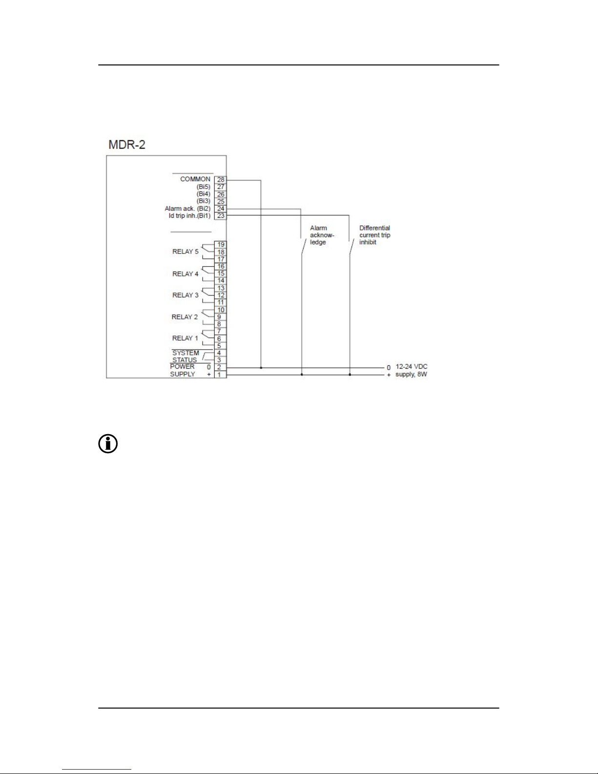
5.1.3 DC connections, inputs and outputs
Alarms can be acknowledged by:
1) Using the display
2) Activating the alarm acknowledge input
3) Auto acknowledge. The use of this is selected in the setup menus.
MDR-2 DRH 4189340300 UK Wiring diagrams
DEIF A/S Page 20 of 26
Page 21
6. Parameter programming
6.1 Programming
6.1.1 About programming
All settings can be programmed using the DEIF utility software for Multi-line 2 or via the display. All parameters are protected by a password.
In the following, the term "No." (number) refers to a specific number used for each setting. The first digit in the
number indicates which group the setting belongs to.
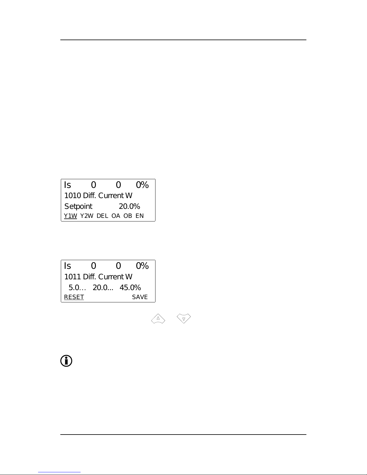
6.1.2 Parameter setting method in display
The parameter setting menu is chosen by placing the cursor (underscore) under “PROT” (move the cursor
with the buttons) in the lower line of the display and pressing “SEL”.
The following display appears:
Y1W Y2W DEL OA OB EN
Is 0 0 0%
1010 Diff. Current W
Setpoint 20.0%
As it can be seen, the cursor is placed under “Y1W”.
If “SEL” is pressed, the setting of set point Y1W is entered (password-protected):
RESET SAVE
Is 0 0 0%
1011 Diff. Current W
5.0… 20.0... 45.0%
The value can now be changed with the and buttons.
When a value is to be stored, remember to move the cursor to "SAVE" and then press "SEL".
Explanations for the different possible setting are made in the next paragraphs.
In these displays, the "VIEW" button can be used to change the upper line reading.
6.2 Differential current
6.2.1 Settings
The setting of differential current warning/trip is done by using five set points:
● Common for trip and warning is SP-X1 (placed under trip (curve 2) setting)
MDR-2 DRH 4189340300 UK
Parameter programming
DEIF A/S Page 21 of 26
Page 22

● Warning Y1W and Y2W
● Trip Y1T and Y2T
100% 200% 300% 400% 500%
Trip at fixed value 100%
Trip at fixed value 85%
Upper limit
Lower limit
Trip Y1T
Warn. Y1W
Trip Y2T
Warn. Y2W
SP-X1
0%
50%
100%
Adjustable warning curve
Adjustable trip curve
Id
In
Is
In
6.2.2 Warning (curve 1)
No. Setting Min. setting Max. setting Factory setting
1010 Diff. current warning Selection display - - -
1011 Diff. current warning SP-Y value 1 warning, Y1W 5 % 45 % 20 %
1012 Diff. current warning SP-Y value 2 warning, Y2W 25 % 95 % 55 %
1013 Diff. current warning Delay 0.01 s 2.00 s 0.10 s
1014 Diff. current warning Relay output A R0 (none) R5 (relay 5) R3 (relay 3)
1015 Diff. current warning Relay output B R0 (none) R5 (relay 5) R5 (relay 5)
1016 Diff. current warning Enable OFF ON ON
6.2.3 Trip (curve 2)
No. Setting Min. setting Max. setting Factory setting
1020 Diff. current trip Selection display - - -
1021 Diff. current trip SP-X value 1 warn/trip, X1 50 % 300 % 100 %
1022 Diff. current trip SP-Y value 1 trip, Y1T 5 % 45 % 25 %
1023 Diff. current trip SP-Y value 2 trip, Y2T 25 % 95 % 70 %
1024 Diff. current trip Delay 0.01 s 2.00 s 0.10 s
1025 Diff. current trip Relay output A R0 (none) R5 (relay 5) R4 (relay 4)
1026 Diff. current trip Relay output B R0 (none) R5 (relay 5) R5 (relay 5)
MDR-2 DRH 4189340300 UK Parameter programming
DEIF A/S Page 22 of 26
Page 23

6.2.4 Trip (fixed trip value)
The fixed trip value refers to tripping when the differential current is 100 % or more.
No. Setting Min. setting Max. setting Factory setting
1030 Diff. fixed limit trip Selection display - - -
1031 Diff. fixed limit trip Delay 0.01 s 2.00 s 0.05 s
The relays (max. two) to be activated are chosen under Trip (curve 2).
6.2.5 Use of relay outputs
For each function (warning and trip), two relay outputs can be set (relay output A and B). For both of these,
any of the relays available (standard: relay 1-5) can be used.
Due to the fact that tripping the generator breaker is insufficient in case of a differential current failure, a total
generator shutdown must be carried out. Dependent on the AVR (Automatic Voltage Regulator) in question,
the AVR should also be tripped, ensuring that the generator voltage is removed immediately. It is suggested
to use for example relay output A to trip the breaker and relay output B to trip the AVR. Alternatively, if that is
not possible, to shut down the engine.
The reason for this shutdown is to stop the damaging current flow caused by the internal failure (differential
current).
If warning or trip messages are to be sent to an alarm system, it is suggested to use separate relays for each
warning or trip alarm sent to the alarm system. This enables the alarm system to identify the cause of alarm.
6.3 Other settings
6.3.1 Status LED
This setting enables/disables the use of yellow light in the protection LEDs. When set ON, the LEDs for I>>,
I> and Id will indicate an alarm status (yellow), if the alarm set point is exceeded, but the delay timer is still
running. If the timer has run out (the alarm is triggered), the LED will be red.
No. Setting First setting Second setting Factory setting
4300 Status info via LED Selection display - - -
4301 Status info via LED Show status OFF ON OFF
6.3.2 Auto acknowledgement of alarms
Automatic acknowledgement of alarms is activated by turning setting 4312 ON.
No. Setting Min. setting Max. setting Factory setting
4310 Auto acknowledge Selection display - - -
4311 Auto acknowledge Delay 0.10 s 10.00 s 2.00 s
4312 Auto acknowledge Enable OFF ON OFF
MDR-2 DRH 4189340300 UK Parameter programming
DEIF A/S Page 23 of 26
Page 24

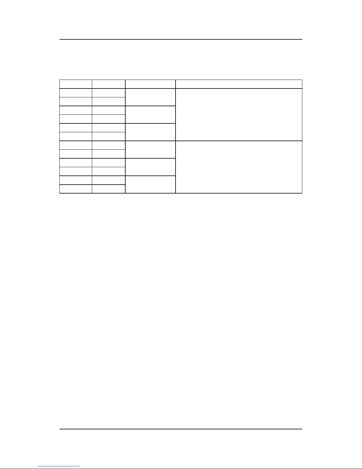
6.3.3 Service menu
The service menu can only be entered using the "JUMP" push button. In this menu, status and timers can be
seen (useful in commissioning situations).
No. Setting Min. setting
4980 Service menu Selection display -
4981 Service menu Alarm Shows remaining delay time
4982 Service menu Digital input Shows digital input status
4983 Service menu Relay output Shows relay output status
6.4 Nominal settings
6.4.1 Nominal current
The nominal current is the nominal current of the generator.
No. Setting Min. setting Max. setting Factory setting
4010 Nominal settings Selection display - - -
4011 Nominal settings Nominal frequency 48 Hz 62 Hz 50 Hz
4012 Nominal settings Nominal current 1 A 10000 A 787 A
If the generator/motor is delta-coupled, the nominal current setting is to be the name plate current divided by √3.
6.4.2 Current transformers
The six current transformers are to be placed like this:
Object under testPrimary side
(I1)
Secondary side
(I2)
I1L1
I1L2
I1L3
I2L1
I2L2
I2L3
The object under test can be:
- A generator
- An electric motor
Transformer ratio for current measurements I1L1, I1L2, I1L3, I2 L1, I2L2 and I2L3.
MDR-2 DRH 4189340300 UK
Parameter programming
DEIF A/S Page 24 of 26
Page 25

No. Setting Min. setting Max. setting Factory setting
4020 Trafo ratio Selection display - - -
4021 Trafo ratio Current prim. 5 A 10000 A 1000 A
4022 Trafo ratio Current sec. 1 A 5 A 1 A
6.4.3 Date and time (internal clock)
No. Setting Min. setting Max. setting Factory setting
4100 Date and
time
Selection
display
- - -
4101 Date and
time
Year
Factory setting is random. Time and date must be set during commissioning.
4102 Date and
time
Month
4103 Date and
time
Date
4104 Date and
time
Hour
4105 Date and
time
Minute
6.4.4 Power supply (battery) under-voltage alarm
No. Setting Min. setting Max. setting Factory setting
4220 Battery low V Selection display - - -
4221 Battery low V Set point 8.0 V 24.0 V 18.0 V
4222 Battery low V Time 0.00 s 10.00 s 1.00 s
4223 Battery low V Relay output A R0 (none) R5 (relay 5) R0 (none)
4224 Battery low V Relay output B R0 (none) R5 (relay 5) R0 (none)
4225 Battery low V Enable OFF ON ON
6.4.5 User password for programming via display
The user password can only be entered using the "JUMP" push-button on the display.
No. Setting Min. setting Max. setting Factory setting
4971 User password Setting 0 32000 2000
MDR-2 DRH 4189340300 UK Parameter programming
DEIF A/S Page 25 of 26
Page 26

6.4.6 Language selection
No. Setting Setting Factory setting
4230 Language Selection display - -
4231 Language English 0 1
Deutsch 1 -
Français 2 -
Español 3 -
MDR-2 DRH 4189340300 UK Parameter programming
DEIF A/S Page 26 of 26
 Loading...