

DEI PCX-7401 Operation Manual
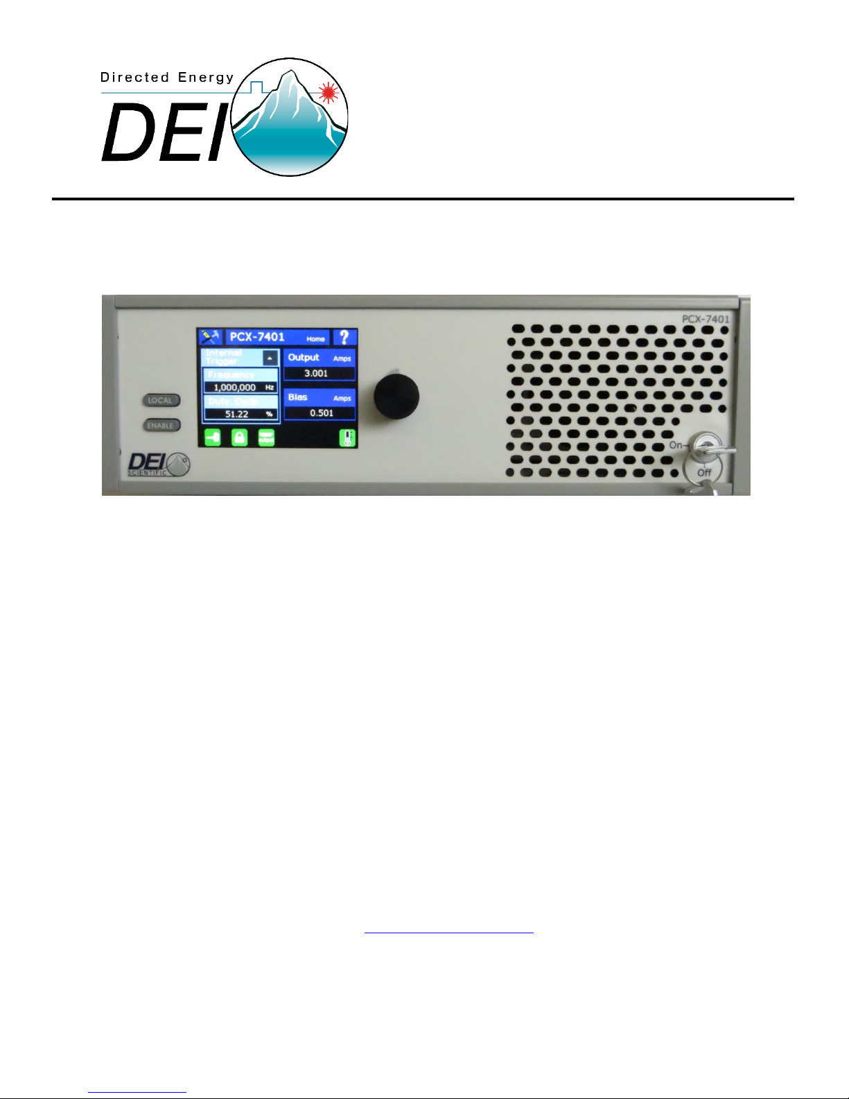
PCX-7401
Pulsed Current Source
Operation Manual
Directed Energy, Inc.
1609 Oakridge Dr., Suite 100, Fort Collins, CO 80525
(970) 493-1901
sales@directedenergy.com
Document #7650-0005 Rev D1. © Copyright 2018 Directed Energy, Inc. All rights reserved.

Contents
Contents ........................................................................................................................................................ 2
Safety ............................................................................................................................................................ 4
Quick Start Guide .......................................................................................................................................... 5
Safety ................................................................................................................................................ 5
Requirements .................................................................................................................................... 5
Controlling the PCX-7401 from the front panel ................................................................................ 5
Controlling the PCX-7401 from a computer ..................................................................................... 6
Introduction .................................................................................................................................................. 7
Description ........................................................................................................................................ 7
Panel Layout ...................................................................................................................................... 8
Front Panel Features ......................................................................................................................... 8
Rear Panel Features .......................................................................................................................... 9
Accessories Included ....................................................................................................................... 10
Operation .................................................................................................................................................... 13
Setup ............................................................................................................................................... 13
Power Up......................................................................................................................................... 13
Home Help Screen .......................................................................................................................... 14
Set the Output Current ................................................................................................................... 14
Set the Bias Current ........................................................................................................................ 14
Set the Trigger Source ..................................................................................................................... 15
Set the Frequency ........................................................................................................................... 15
Set the Duty Cycle ........................................................................................................................... 16
Set the Single Shot .......................................................................................................................... 17
Settings Menu ................................................................................................................................. 18
View Information About the PCX-7401 ........................................................................................... 18

View the Communication Settings .................................................................................................. 19
Save Settings ................................................................................................................................... 21
Recall Settings ................................................................................................................................. 21
Power Down .................................................................................................................................... 21
Command Set .............................................................................................................................................. 22
Warranty and Service .................................................................................................................................. 27
Warranty ......................................................................................................................................... 27
Factory Service and Support ........................................................................................................... 28
CE DECLARATION OF CONFORMITY ............................................................................................................ 29

Safety
• Do not open the cover of PCX-7401. There are no user-serviceable parts inside.
Opening the cover exposes you to shock and voids the factory warranty.
• Do not install, handle, or remove the output cables or laser diode while the PCX7401 is operating. Allow at least 10 minutes after power-down before handling
the output cable or laser diode.
• Do not use this device in a manner not specified by the manufacturer.
• Allow sufficient space around this device for air circulation. Cooling air enters the
front of the chassis and exits the back of the chassis.
• Do not use where liquids are present or in corrosive environments. Clean this
instrument by wiping with a dry or damp cloth.
WARNING
Risk of lethal electric shock. Do not open the cabinet of this device. Do not touch
the output or laser diode while it is operating. This device produces LETHAL
levels of electric current, both inside its cabinet and at its output.
DO NOT OPERATE THIS DEVICE UNLESS ANOTHER PERSON, CAPABLE OF
RENDERING FIRST AID OR RESUSCITATION IS PRESENT.
SAFE AND PROPER OPERATION OF THIS DEVICE IS THE RESPONSIBILITY OF
THE USER.
Directed Energy, Inc. (DEI) provides information on its products and associated
hazards, but it assumes no responsibility for the after-sale operation and safety
practices.
For more information contact us: 970.493.1901 or sales@directedenergy.com
Document #7650-0005 Rev D1. © Copyright 2018 Directed Energy, Inc. All rights reserved.
Page 4 of 32

Quick Start Guide
Safety
Follow the safety guidelines on previous page. DO NOT PROCEED WITHOUT
UNDERSTANDING AND OBSERVING THESE GUIDELINES.
Requirements
Make sure the PCX-7401 is:
• connected with the proper cables and termination impedance
• powered up
• Has all faults cleared
• Has the rear enable and keyswitch enabled. The proper icons will be
green when enabled.
Controlling the PCX-7401 from the front panel
1. Disable the PCX-7401
The Enable button on the front panel glows green if the PCX-7401 is
enabled. Press the button to disable. The green light goes out.
2. Set the output current.
Press the Output button on the touch screen.
Press the encoder knob to set the resolution.
Turn the encoder knob to set the output current from 0.000 A to 3.000 A.
Press the Done button.
3. Set the bias current.
Press the Bias button on the touch screen.
Press the encoder knob to set the resolution.
Turn the encoder knob to set the bias current from 0 .000 A to 0.550 A.
Press the Done button.
4. Set the trigger to internal, external, or single shot, as needed.
Press the Trigger button on the touch screen.
Press the Internal or External or Single Shot button to select the trigger.
5. Set the internal pulse trigger frequency
Press the Frequency icon on the touch screen.
Press the encoder knob to set the resolution.
Turn the encoder knob to set the frequency.
Press the Done icon.
For more information contact us: 970.493.1901 or sales@directedenergy.com
Document #7650-0005 Rev D1. © Copyright 2018 Directed Energy, Inc. All rights reserved.
Page 5 of 32

6. Set the duty cycle
Press the Duty Cycle icon on the touch screen.
Press the encoder knob to set the resolution.
Turn the encoder knob to set the duty cycle.
Press the Done icon.
7. Enable the PCX-7401
Press the Enable button on the front panel. The button lights green.
Controlling the PCX-7401 from a computer
1. Disable the PCX-7401
Send the command “OUTPUT:DISABLE”.
2. Set the trigger to internal, external, or single shot, as needed.
Send the command “TRIG:INTERNAL”, “TRIG:EXTERNAL”, or
“TRIG:SINGLESHOT”.
3. Set the internal pulse trigger frequency
Send the command “TRIG:INT:FREQ n”, where n = [5 to 1000000].
Units are hertz.
4. Set the pulse duty cycle
Send the command “TRIG:INT:MAIN:DUTYCYCLE n”, where n = [1.00 to
99.00].
Units are percent.
5. Set the output current
Send the command “MAIN:CURRENT:SETPOINT n”, where n = [0 to
3000].
Units are milliamperes.
6. Set the bias current.
Send the command “BIAS:CURRENT:SETPOINT n”, where n = [0 to 550].
Units are milliamperes.
7. Enable the PCX-7401
Send the command “OUTPUT:ENABLE”.
For more information contact us: 970.493.1901 or sales@directedenergy.com
Document #7650-0005 Rev D1. © Copyright 2018 Directed Energy, Inc. All rights reserved.
Page 6 of 32

Introduction
Description
The PCX-7401 is a precision pulsed current source for driving laser diodes, bars,
and arrays. It delivers current pulses variable from 0.000 A to 3.000 A, with a bias
current from 0.000 A to 0.550 A. An internal trigger provides pulse repetition
frequencies from 5 Hz to 1.000 MHz and duty cycles of 1.00 % to 99.00 %.
The internal Single-shot pulse is adjustable in pulse widths ranging from 200 ns to
1.000000000 second. The single shot is easily enabled using the Enable button on
the front panel.
The system can be fully adjusted by using the color touch screen or by using a
computer interface. System adjustments include the main output current amplitude,
bias current amplitude, main pulse width, trigger source, trigger frequency, duty
cycle, and single shot pulse width.
The bias feature allows the PCX-7401 to deliver the current pulse in two steps. The
first step—the bias DC—is turned on before the intended trigger time, and is
adjusted to supply enough current to set the laser diode just below the trigger point
of the laser diode. This minimizes the laser diode’s response time to the main pulse.
The second step—the main pulse—adds to the current from the bias pulse and
triggers the diode at the intended time. The main pulse amplitude is variable from
0.000 A to 3.000 A. Its duty cycle is variable from 1.00 % to 99.00 %.
The total current output pulse is always the sum of the bias current and the main
pulse current. Consider both the bias output current and the main output current
when setting the total output current.
The PCX-7401 can be triggered internally or externally, and readily synchronized
with other devices via a Sync output signal on the rear panel. The input termination
impedance for the external trigger is selectable for either 50 Ω or 10000 Ω. The Sync
signal amplitude varies between 0 and +5.0V. The rising edge corresponds to the
rising edge of the main output current pulse. The delay between the sync output
signal and the main output current pulse is ~100 ns, measured from rising edge to
rising edge.
The PCX-7401 has the ability to store four unique user settings, which include all
system configurations for operation of the PCX-7401.
For more information contact us: 970.493.1901 or sales@directedenergy.com
Document #7650-0005 Rev D1. © Copyright 2018 Directed Energy, Inc. All rights reserved.
Page 7 of 32
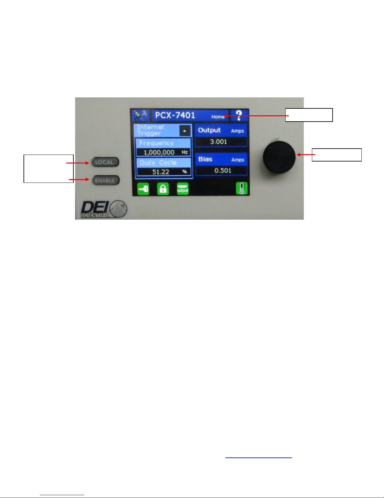
Panel Layout
Local Button
Enable Button
Touch Screen
Encoder Knob
All features of the front touch screen and the rear panel are labeled. Their functions
are covered in the next sections.
Front Panel Features
Local Button Mode
Pressing the LOCAL button returns the PCX-7401 to front panel control from
computer control. The Local button is lit when the computer is in control.
Enable Button Mode
The ENABLE button selects whether the PCX-7401 output current is enabled or
disabled. The Enable button is lit when the unit is enabled.
Touch Screen
The touch screen provides a graphical user interface and touch control to adjust all
functions of the PCX-7401.
Encoder Knob
Turn the encoder knob to change a value for functions of the PCX-7401. Push it to
cycle through the resolutions (increments of value change).
Keyswitch
The Keyswitch ON allows the PCX-7401 output current to be enabled. OFF disables
the PCX-7401.
For more information contact us: 970.493.1901 or sales@directedenergy.com
Document #7650-0005 Rev D1. © Copyright 2018 Directed Energy, Inc. All rights reserved.
Page 8 of 32
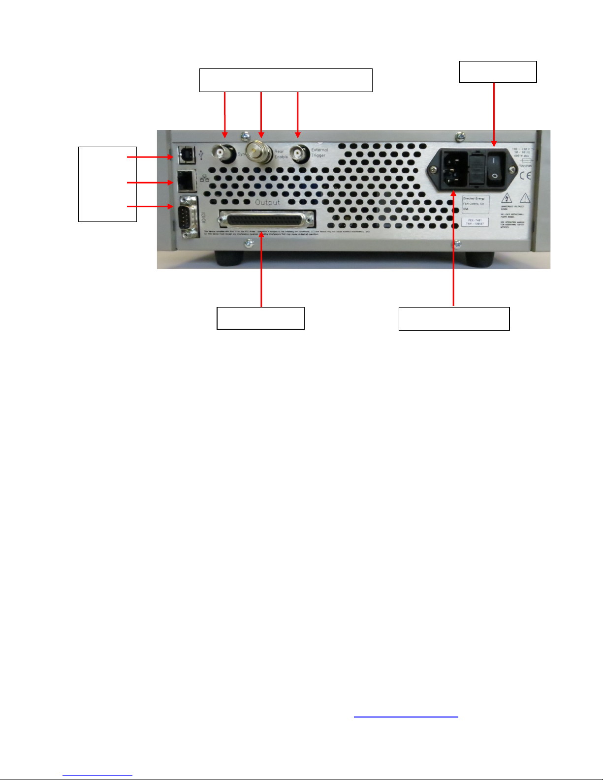
Power Switch
Current Output
Sync, Rear Enable, External Trigger
USB
AC Power Connector
Ethernet
RS232
Rear Panel Features
Current Output
A socket that accepts the factory-supplied output cable, and is the connection for the
system generated current pulses. DO NOT TOUCH any part of this cable while the
PCX-7401 is powered up. Please review the Safety section.
Note: Absence of a properly installed output cable disables the output and creates
an output enable fault.
Sync Output
Synchronization pulses for external devices are available at this BNC connector. The
sync pulse corresponds to the leading edge of the output current pulse.
Rear Enable
This connector accepts either an external dry-contact closure or the factory-supplied
shorting BNC plug. Closed contacts or use of the shorting plug enables the output.
Open contacts or removal of the shorting plug disables the output and creates a rear
enable fault.
USB Connector
Use this connector to communicate with an external computer with a USB cable.
For more information contact us: 970.493.1901 or sales@directedenergy.com
Document #7650-0005 Rev D1. © Copyright 2018 Directed Energy, Inc. All rights reserved.
Page 9 of 32
Ethernet Connector
Use this connector to communicate with an external computer through an Ethernet
network.
RS232 Connector
Use this connector to communicate with an external computer via a RS232 cable.
Power Cord Connector
The power cord connector accepts a standard grounding equipment power cord,
connector type NEMA C-14.
On-Off Power Switch
This switches powers the PCX-7401 on and off.
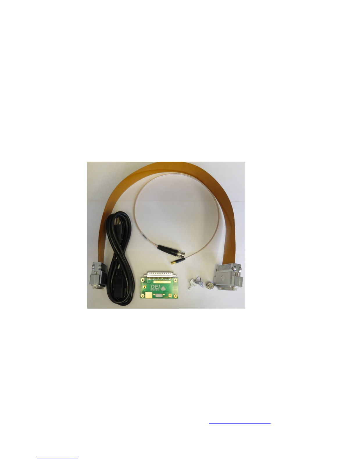
Accessories Included
AC Power Cord
Factory-supplied standard computer-style power cord, with a NEMA C14
and a NEMA 5-15R connectors.
Current/Voltage Monitor Cable
This factory-supplied cable (PCA-9550) connects the laser output PCBA to a
monitoring instrument, such as an oscilloscope.
For more information contact us: 970.493.1901 or sales@directedenergy.com
Document #7650-0005 Rev D1. © Copyright 2018 Directed Energy, Inc. All rights reserved.
Page 10 of 32
 Loading...