

Page 1

Dodge Engineering & Controls, Inc.
Toll Free (877) 334-2875 Fax: (978) 244-1422
ES142 Spring Return Electronic Actuators
b
a
e
EA0655R1
c
Figure 1. Parts of the ES142 Actuator.
Product Description
This installation instruction describes the steps for
direct-coupled mounting the ES142 series spring
return electronic actuator.
Product Numbers
ES142 (all versions)
Installation
a. Actuator
b. Shaft adapter
d
g
f
c. Position indicator
d. Shaft adapter locking
clip
e. Position indicator
adapter
h
f. Mounting bracket
(for dampe
g. Mounting screws
h. 3 mm hex wrench
rs)
Required Tools
• 10 mm (13/32 in. open end wrench or ratchet
• Drill
• 4 mm (5/32 in.) drill bit
• 3 mm hex wrench (provided)
• Phillips screwdriver
• Marker or pencil
Installation Conventions
Warning
Caution
Personal injury or loss of life may
occur if you do not perform a
procedure as specified.
Equipment damage or loss of data
may occur if you do not follow a
pro
edure as specified.
c
Expected Installation Time
30 minutes
Prerequisites
NOTE: The actuator is shipped from the factory
with a 5° preload on the spring. The
position of the indicator points to the 0°
position. When power is applied to the
actuator, the preload is released.
WARNING:
Do not open the actuator.
129-270 EAI/ES-1 DEI, Inc.
Page 2

Installation
Dodge Engineering & Controls, Inc.
Toll Free (877) 334-2875 Fax: (978) 244-1422
ES142 Spring Return Electronic Actuators
1
Installation
90¡
2
Manual
Overide
EA1119R1
NOTE: The actuator can be mounted for clockwise or counterclockwi
Figure 2. Actuator Mounting Orientation.
d
>
77 mm
>3 in
5
4
a
90¡
2
Manual
Overide
se rotation of the damper shaft.
cc
c
c
b
6
6
3
>20 mm
<
77 mm
>3/4 in
<3 in
EA0656R1
NOTE: The shaft coupling and position indicator can be mounted on either side of the actuator.
Place the sha
129-270 EAI/ES-2 DEI, Inc.
ft adapter right next to the alignment mark keeping the mark visible.
Figure 3. Shaft Length and Proper Shaft Adapter Location.
4
SHAFT
ADAPTER
5
d
b
ALIGNMENT
MARK
90
6
a
e
cc
7
7
Page 3
Dodge Engineering & Controls, Inc.
Toll Free (877) 334-2875 Fax: (978) 244-1422
Installation
ES142 Spring Return Electronic Actuators
OR
1
4
3
3
4
2
EA0289R2
OVERRIDE
MANUAL
OVERRIDE
MANUAL
EA0288R1
r bla
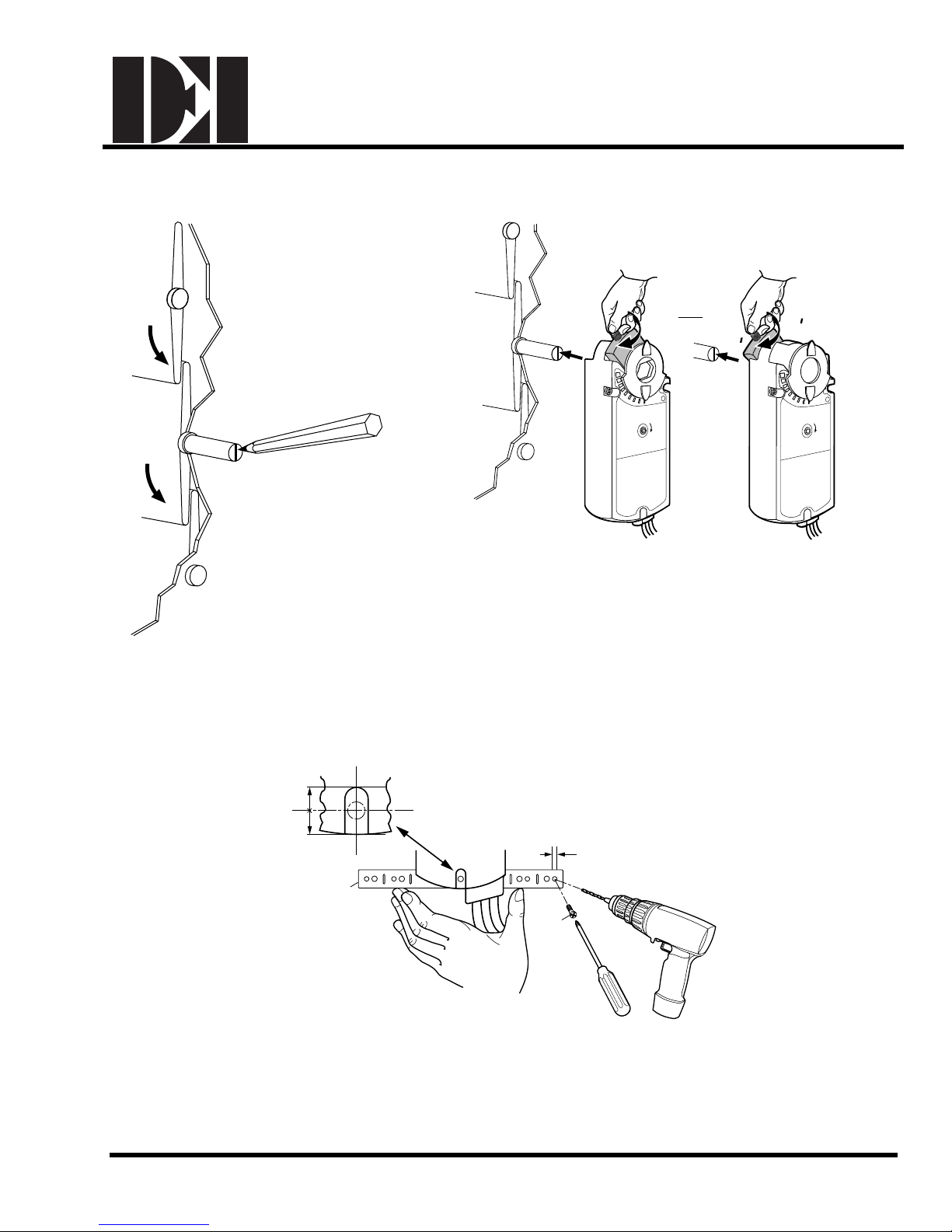
Place the actuator on the shaft with the dampe
des in the desired 0 position.
Tighten the middle screw so that the shaft is in the center of the shaft adapter opening.
Figure 4. Actuator Mounting.
1/2
1/2
5
f
4 mm
5/32 in.
2 PLACES
Anti-rotation tab should be approximately in the center
129-270 EAI/ES-3 DEI, Inc.
g
EA0357R2
6
of the actuator anti-rotation slot.
Figure 5. Fasten the Mounting Bracket.
Page 4

Dodge Engineering & Controls, Inc.
Toll Free (877) 334-2875 Fax: (978) 244-1422
Installation
ES142 Spring Return Electronic Actuators
NOTE: Keep the shaft in the ce
Manual Override
90˚
90˚
Manual
Override
GEAR TRAIN
LOCK PIN
EA0697R1
10 mm HEX
SOCKET
88 lb. - in.
(10Nm) TORQUE
10 mm HEX
SOCKET
88 lb. - in.
(10Nm) TORQUE
nter of the shaft adapter opening. Apply 7.5 lb-ft (10 Nm) torque maximum.
Figure 6. Fasten the Shaft Adapter to the Damper Shaft.
x 7-3/4 = 90˚
2
1
h
3 mm
Manual
Override
GEAR TRAIN
LOCK PIN
3
HOLD
5
90˚
7
Manual
Override
GEAR TRAIN
LOCK PIN
6
8
EA0374R3
Rotating
Turn the key in the direction of
the arrow on
the hand symbol.
CAUTION:
When you lock the gear train lock pin, be careful to turn only about 5 degree
click or meet slight resistance. Turning too far will strip the head of the lock pin. Once power is
restored, the actuator returns to automated control, without having to rotate the gear train lock pin.
129-270 EAI/ES-4 DEI, Inc.
4
Locking in place
Rotate the gear train
lock pin.
Figure 7. Manual Override.
Releasing when power is absent
Turn the key in the direction of the
arrow.
s until you hear a light
Page 5

Dodge Engineering & Controls, Inc.
Toll Free (877) 334-2875 Fax: (978) 244-1422
ES142 Spring Return Electronic Actuators
Mechanical Range Adjustment –
Limiting Rotation (0 through 90°)
Make sure the actuator is in the zero position when
ng this adjustment. If making the adjustment
maki
before the actuator is in service, take into account the
5° preload. To release the preload, insert the 3 mm hex
key in the override opening and turn the key in the
direction of the arrow.
To line up the actuator at the desired angle of rotation,
begin by rem
Rotate adapter and insert at desired angle of rotation.
Return clam
applying signal.
If necessary, re-adjust adapter and restart.
oving the clamp from actuator.
p to secure the adapter. Test rotation by
Installation
1
2
3
EA0701R1
Figure 8.
The Angular Rotation is Adjustable between
0° and 90° at 5-degree Intervals.
5
Mounting for NEMA 2
See Figure 10 for acceptable NEMA 2 mounting
positions.
90
4
EA0660R1
Figure 9.
NEMA 2
<
90
˚
EA0692R1
Figure 10. Acceptable NEMA 2 Mounting Positions.
˚
90
<
˚
90
129-270 EAI/ES-5 DEI, Inc.
Page 6

Dodge Engineering & Controls, Inc.
Toll Free (877) 334-2875 Fax: (978) 244-1422
ES142 Spring Return Electronic Actuators
DIP Switch Features
(ES142-M2 and ES142-M2-S Only)
Installation
Counterclockwise
Self-adapt feature
2 to 10 Vdc
Tandem Mount
Master
Figure 11. DIP Switch Settings.
After setting the 4th DIP switch for TM (tandem mount) on all actuators used in the
•
tandem ap
"M" on the 5th DIP switch.
• The rest of the actuators used in the applicatio
the 5th DIP switch.
• Connect all the 2 (black) Neutral wires a
• Connect all the 1 (red) Supply wires and connect them to the power supply.
• The Output Signal 9 (pink) wire identified as the Master actuator, needs to be
connected to all the Control Signal Wires 8 (gray) of the slave actuators used in the
tandem application.
plication, one actuator must be identified as the Master by selecting the
Operating
Voltage
Modulating Control
24 Vac/dc 9 VA/7W
2-Position and 3-Position Control
24 Vac/dc 8 VA/6W
120 Vac 9 VA
Power
Consumption
Clockwise
Self-Adapt Off
0 to 10 Vdc
Single Mount
Slave
n should have the "S" (slave) set on
nd connect them to the power supply.
129-270 EAI/ES-6 DEI, Inc.
Page 7
Dodge Engineering & Controls, Inc.
Toll Free (877) 334-2875 Fax: (978) 244-1422
ES142 Spring Return Electronic Actuators
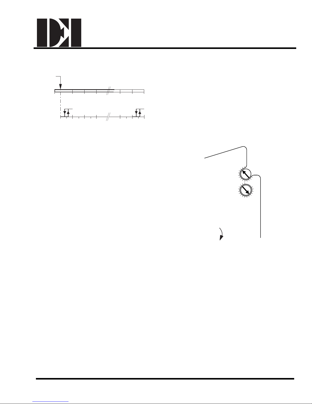
Dual Auxiliary Switch (-S option)
Installation
-5° 0° 10° 20° 30° 70° 80° 90°
0° 10° 20° 30° 70° 80° 90°
EA0413R2
A
Figure 12.
B
Factory setting:
Switch A 5°
Switch B 85°
To change the settings of A and B:
•
Make sure the actuator is in the 0 position. The
scale is valid
only in the 0 position.
• Use a flat-blade screwdriver to turn the switch
stment dials to the desired setting at which a
adju
signal is to be given.
Actuator rotary range with the shaft adapter mounted at
positio
n 0.
Setting rang
Setting interval: 5°
e for Switches A and B: 0 – 90°
Switching hysteresis: 2°
10
20
A
AUX
SWITCH
ADJ
B
40
30
40
70
20
90
80
70
50
60
Manual
Override
EA0277R3
Figure 13. Dual Auxiliary Switch Dials.
129-270 EAI/ES-7 DEI, Inc.
Page 8
Dodge Engineering & Controls, Inc.
Toll Free (877) 334-2875 Fax: (978) 244-1422
ES142 Spring Return Electronic Actuators
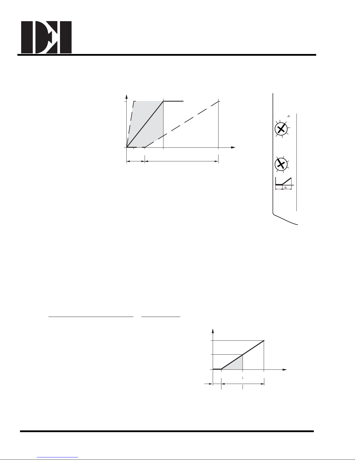
Zero Span Control Signal Adjustment (-ZS option)
The offset (start point) and
of the control signal
span
can be adjusted. The offset,
U0, can be adjusted between
0 to 5 VDC. The span, ∆U,
can be adjusted between 2
to 30 VDC.
Y
(%)
S
100
0
2 5 10 35
EA0411R1
U
O
U (max. 30 V)
Δ
Ys Mechanical positioning ra nge
(100% = angl
e of rotation 90°)
Yu Control signal
U0 Offset (start point)
∆U Span
Installation
2)1) 3)
Control
Signals
Span, U
5
2
10
15
20
30
25
Y
(v)
U
Offset, Uo
1
0
5
4
Uo
2
3
U
Examples above:
Ex. 1. U0 = 0V, ∆U = 2V The minimu
range for Ys = 100%.
Ex. 2. U0 = 5V, ∆U = 30V The maximu
range for Ys = 100%
Ex. 3. U0 = 0V, ∆U = 10V
Figure 14. The Minimum and Maximum Control Signal
Factory setting
Adjustment.
Example:
t
Open the actuator from 0% to 50% (45°) using a con
rol signal of Umin = 2V to Umax = 10V.
Calculating the value of ∆U:
50
2)(10 x 100
−
V16
Y
(%)
S
100
50
min) Umax (U %] [ 100
U =
=Δ
−
=
% in rotation of angle Working
Settings:
Offset U0 = 2, Span: ∆U = 16V
Umin = mi
nimum control signal
Umax = maximum control signal
m working
m working
0
21810
U
o
ΔU (16 V)
EA0287R1
Figure 15. Setting for
10V Span, 0 Offset.
Y
(v)
U
129-270 EAI/ES-8 DEI, Inc.
U
EA0412R1
min
Figure 16. Example.
U
max
Page 9
Dodge Engineering & Controls, Inc.
Toll Free (877) 334-2875 Fax: (978) 244-1422
Installation
ES142 Spring Return Electronic Actuators
Wiring
24 VAC or 120 VAC
All wiring must conform to NEC and local codes and regulations.
24 VAC
Use earth ground isolating step-down Class 2 transformers. Do not use auto transformers. Determine the supply
transformer rating by summing the total VA of all actuators used. The maximum rating for a Class 2 step-down
transformer is 100 VA. The ES142 (24 VAC) actuators require 8 to 9 VA; therefore it is recommended that up to
10 actuators (between 80 and 90% of transformer VA) can be powered by one transformer. Operating more than
10 actuators requires additional transformers or separate 100 VA power trunks.
WARNING:
Mixed switch operation is not permitted. To the switching output
only apply:
• Standard cable (250 Vac/24 Vdc)
− UL/cUL: line voltage, or
− UL/cUL: Class 2 voltage.
s of both auxiliary switches (A and B),
NOTE
: Either all six outputs of the dual auxiliary
outputs must be connected to Class 2 voltage.
• Plenum cable (24V)
− UL/cUL: Class 2 voltage.
Wiring Diagrams
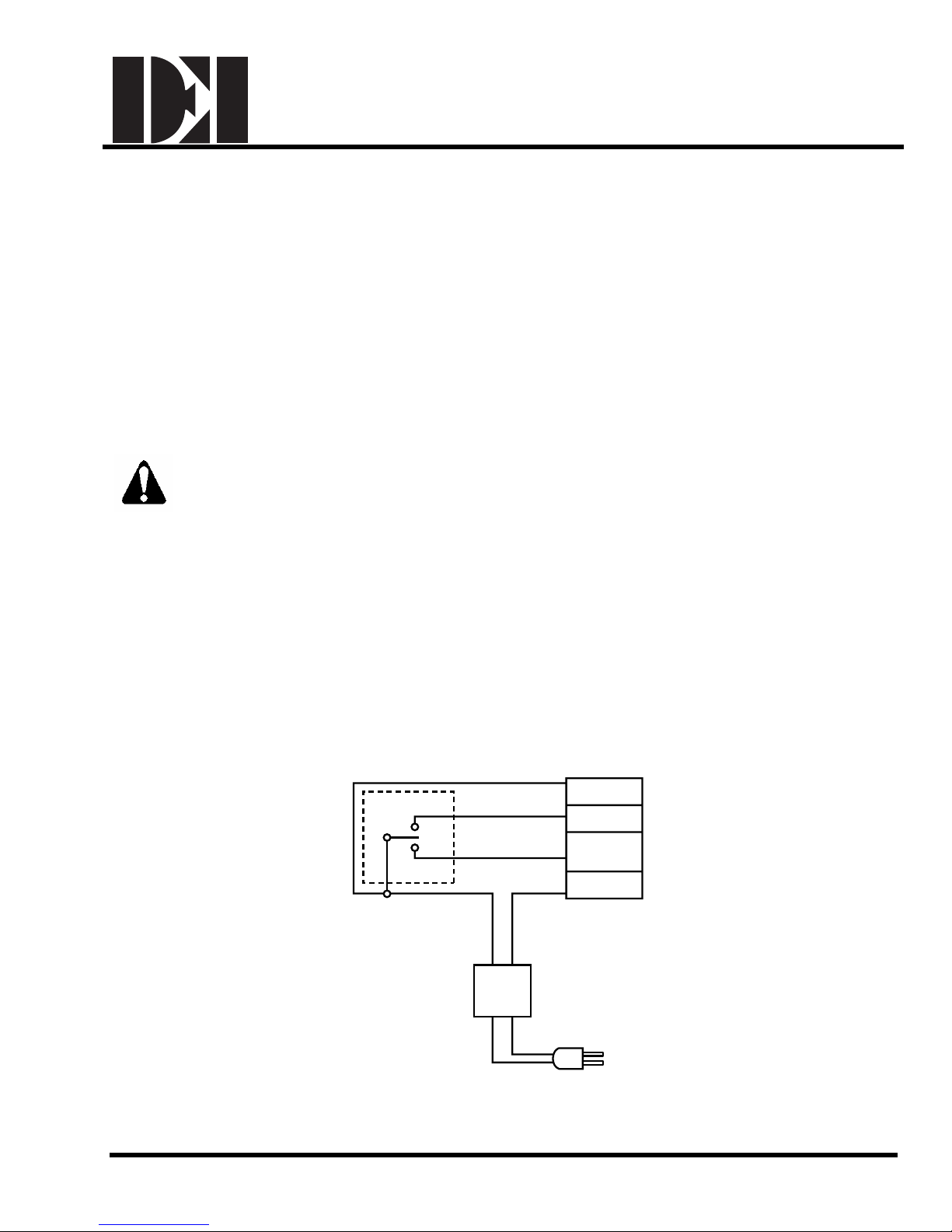
Three-Position Control (24 VAC/DC)
NEUT
switches must be connected to line voltage or all six
2 (BLACK)
7 (ORANGE)
6 (VIOLET)
1 (RED)
24
Vac
EARTH GROUND
ISOLATING CLASS 2
TRANSFORMER FOR
24 Vac POWER
129-270 EAI/ES-9 DEI, Inc.
EA0868R1
Figure 17. Three-Position Control.
120 Vac
Page 10
Dodge Engineering & Controls, Inc.
Toll Free (877) 334-2875 Fax: (978) 244-1422
Installation
ES142 Spring Return Electronic Actuators
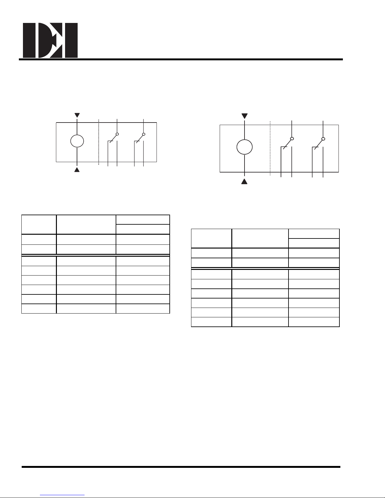
Two-Position Control (24 VAC/DC)
1
M
EA0281R1
2
Figure. 18
Table 1. Two-position Control 24 VAC/DC.
Standard
Symbol
1
2 Com Black
S1 Switch A Common Gray/red
S2 Switch A N.C. Gray/blue
S3 Switch A N.O. Gray/pink
S4 Switch B Common Black/red
S5 Switch B N.C. Black/blue
S6 Switch B N.O. Black/pink
Function
(+)
S1
A
S2 S3 S5 S6
Red
S4
B
Color
Plenum
Two-Position Control (120 VAC)
3
M
PL0026R1
4
Figure 19.
Table 2. Two-position Control 120 VAC.
Standard
Symbol
3 Line (120 VAC) Black
4 Neutral (120 VAC) White
S1 Switch A Common Gray/red
S2 S witch A N.C. Gray/blue
S3 S witch A N.O. Gray/pink
S4 S witch B Common Black/red
S5 S witch B N.C. Black/blue
S6 S witch B N.O. Black/pink
Function
S1
A
S4
B
S2 S3 S5 S6
Color
Standard
129-270 EAI/ES-10 DEI, Inc.
Page 11
Dodge Engineering & Controls, Inc.
Toll Free (877) 334-2875 Fax: (978) 244-1422
ES142 Spring Return Electronic Actuators
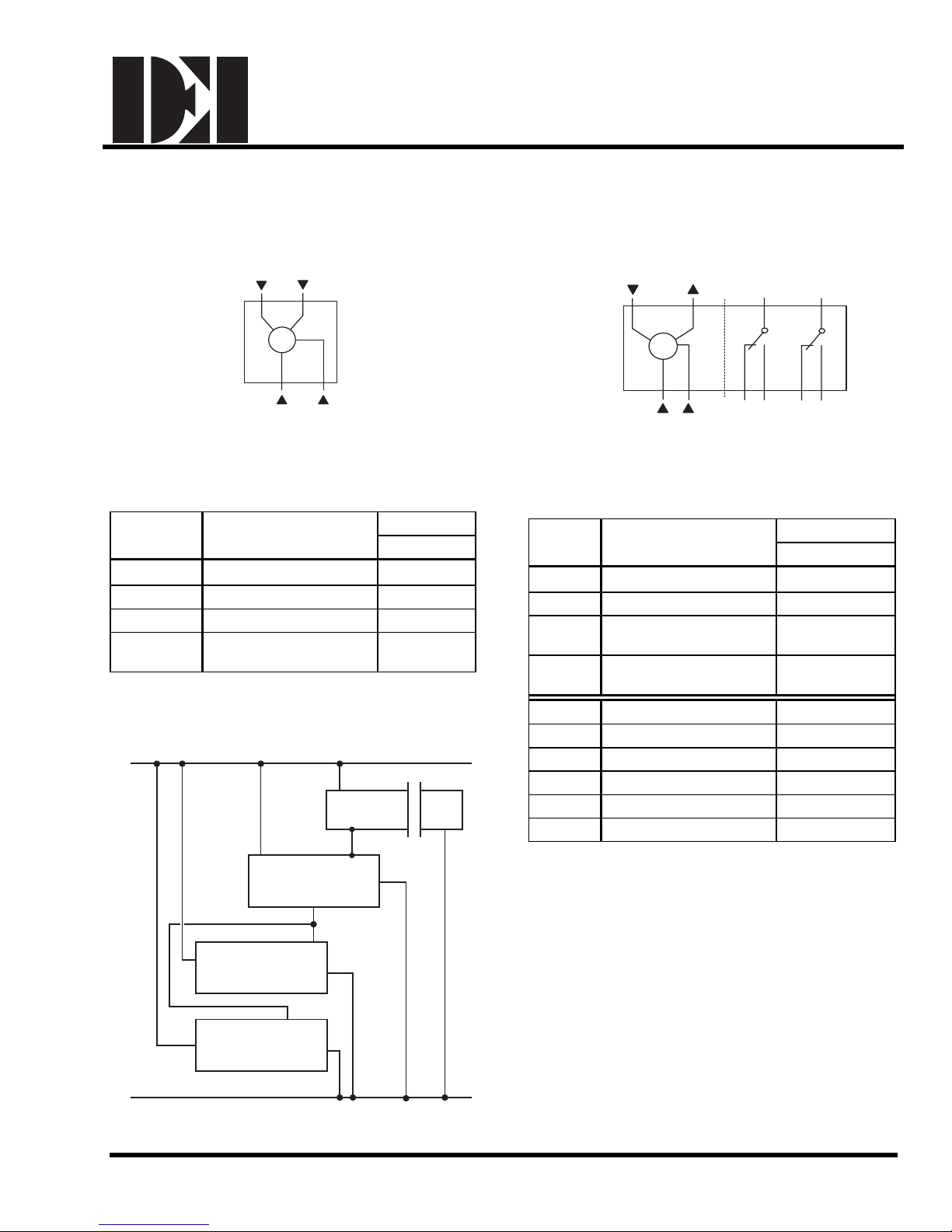
Three-Position Control (24 VAC/DC) Modulating Position Control
CONTROL SIGNAL
CW6CCW
7
(24 VAC/DC)
8
9
S1
Installation
S4
M
2
1
SUPPLY
PL0154R1
NEUTRAL
Figure 20.
Table 3. Three-position Control 24 VAC/DC.
Standard
Symbol
1
Function
(+)
Color
Plenum
Red
2 Com Black
6 Control signal clockwise Violet
7
Control signal
countercl
ockwise
Orange
(0 to 10 Vdc or 2 to 10 Vdc) for Tandem
Application (Master/Slave)
Supply (+)
Controller
Control Signal
0 to 10 Vdc
or 2 to 10 Vdc
Neutral
9
8
2
81
Supply
Actuator 2
Input 0 to 10 Vdc
or 2 to 10 Vdc
1
Supply
8
Input 0 to 10 Vdc
Actuator 1
Output (Feedback)
Neutral
Neutral
2
EA0284R1
M
2
1
A
S2 S3 S5 S6
B
Figure 21.
Table 4. Modulating Control 24 VAC/DC.
Standard
Symbol
1
Function
(+)
Color
Plenum
Red
2 Com Black
0 to 10 VDC/
8
2 to 10 Vdc inp
Output for 0 to 10 VDC
9
position in
ut signal
dication
Gray
Pink
S1 Switch A Common Gray/red
S2 Switch A N.C. Gray/blue
S3 Switch A N.O. Gray/pink
S4 Switch B Common Black/red
S5 Switch B N.C. Black/blue
S6 Switch B N.O. Black/pink
Input 0 to 10 Vdc
Actuator 3
or 2 to 10 Vdc
Neutral
Neutral (-)
EA1217R1
1
Supply
129-270 EAI/ES-11 DEI, Inc.
2
Page 12

Dodge Engineering & Controls, Inc.
Toll Free (877) 334-2875 Fax: (978) 244-1422
Installation
ES142 Spring Return Electronic Actuators
Start-Up/Commissioning
Two-Position Control, 24 VAC/DC
1. Check that the wires ar
2. Connect wires 1 (red) and 2 (black) to a Digital Multimeter (DMM) with the dial set at VAC to verify that the
operating voltage is
3. Che
4. Check spring return:
5. Check the auxiliary switch A (-S option):
6. Check the auxiliary switch B (-S option):
ck operation:
a. Connect wires 1 (red) and 2 (black) to 24 VAC/DC si gnal.
b. Allow the actuator shaft coupling to rotate from 0 to 90°.
c. Disconnect wire 1 (red) and the actuator shaft cou
a. Connect wires 1 (red) and 2 (black) to the 24 VAC/DC signal.
b. Allow the actuator shaft coupling to rotate half-way.
c. Disconnect wire 1 (red).
d. The spring returns the actuator shaft coupling to the fail 0 position.
e. Connect wire 1 (red) and the actuator shaft coupling begins to move.
a.
Set the DMM dial to OHMS (resistance) or continuity check.
b. Connect wires S1 and S3 to the DMM. The DMM should indicate an open circuit or no resistance.
c. Apply a 24 VAC signal to wire 1 (red).
d. The DMM should indicate contact closure as the actuator sh
e. Connect wires S1 and S2 to the DMM. The DMM should indicate an open circuit or no resistance.
f. Disconnect wire 1 (red).
g. The DMM should indicate contact closure as the actuator sh
a.
Set the DMM dial to OHMS (resistance) or continuity check.
b. Connect wires S4 and S6 to the DMM. The DMM should indicate an open circuit or no resistance.
c. Apply a 24 VAC signal to wire 1 (red).
d. The DMM should indicate contact closure as the actuator sh
e. Connect wires S4 and S5 to the DMM. The DMM should indicate an open circuit or no resistance.
f. Disconnect wire 1 (red).
g. The DMM should indicate contact closure as the actuator sh
e connected correctly.
within range.
p
ling returns to the 0 position.
pling reaches the setting of switch A.
aft cou
aft cou
pling reaches the setting of switch A.
pling reaches the setting of switch B.
aft cou
aft cou
pling reaches the setting of switch B.
Service
WARNING:
Do not open the actuator. If the actuator is inoperative, replace the unit.
129-270 EAI/ES-12 DEI, Inc.
Page 13

Dodge Engineering & Controls, Inc.
Toll Free (877) 334-2875 Fax: (978) 244-1422
ES142 Spring Return Electronic Actuators
Two-Position Control, 120 VAC
1. Check that the wires ar
2. Connect wires to a Digital Multimeter (DMM) with the dial set at VAC to verify that the operati
within ra
3. Check operation:
a. Connect wires 3 (black) and 4 (white) to 120 VAC signal.
b. Allow the actuator shaft coupling to rotate from 0 to 90°.
c. Disconnect wire 3 (black) and the actuator shaft coupling returns to the 0 position.
4. Check spring return:
a. Connect wires 3 (black) and 4 (white) to the 120 VAC signal.
b. Allow the actuator shaft coupling to rotate half-way.
c. Disconnect wire 3 (black).
d. The spring returns the actuator shaft coupling to the fail 0 position.
e. Connect wire 3 (black) and the actuator shaft coupling begins to move.
5. Check the auxiliary switch A (-S option):
a.
b. Connect wires S1 and S3 to the DMM. The DMM should indicate an open circuit or no resistance.
c. Apply a 120 VAC across wires 3 (black) and 4 (white).
d. The DMM should indicate contact closure as the actuator sh
e. Connect wires S1 and S2 to the DMM. The DMM should indicate an open circuit or no resistance.
f. Disconnect wire 3 (black).
g. The DMM should indicate contact closure as the actuator sh
6. Check the auxiliary switch B (-S option):
a.
b. Connect wires S4 and S6 to the DMM. The DMM should indicate an open circuit or no resistance.
c. Apply a 120 VAC across wires 3 (black) and 4 (white).
d. The DMM should indicate contact closure as the actuator sh
e. Connect wires S4 and S5 to the DMM. The DMM should indicate an open circuit or no resistance.
f. Disconnect wire 3 (black).
g. The DMM should indicate contact closure as the actuator sh
nge.
Set the DMM dial to OHMS (resistance) or continuity check.
Set the DMM dial to OHMS (resistance) or continuity check.
e connected correctly.
ng voltage is
pling reaches the setting of switch A.
aft cou
aft cou
pling reaches the setting of switch A.
pling reaches the setting of switch B.
aft cou
aft cou
pling reaches the setting of switch B.
Service
WARNING:
Do not open the actuator. If the actuator is inoperative, replace the unit.
Installation
129-270 EAI/ES-13 DEI, Inc.
Page 14

Dodge Engineering & Controls, Inc.
Toll Free (877) 334-2875 Fax: (978) 244-1422
Installation
ES142 Spring Return Electronic Actuators
Three-Position Control, 24 VAC/DC
1. Check that the wires are connected correctly.
2. Connect wires 1 (red) and 2 (black) to a Digital Multimeter (DMM) with the dial set at VAC to verify that the
operating voltage is within range.
3. Che
4. Check spring return:
ck operation:
a. Connect wires 1 (red) and 2 (black) to the actuator.
b. Apply a control signal (24 VAC/DC) to wire 6 (violet).
c. Allow the actuator shaft coupling to rotate from 0 to 90°.
d. Stop applying a control signal to wire 6 (violet).
e. Apply a control signal (24 VAC/DC) to wire 7 (orange).
f. Allow the actuator shaft coupling to rotate from 90 to 0°.
a. Apply a control signal (24 VAC/DC) to wire 6 (violet).
b. Allow the actuator shaft coupling to rotate half-way.
c. Disconnect wire 1 (red).
d. The spring returns the actuator shaft coupling to the fail 0 position.
Service
WARNING:
Do not open the actuator. If the actuator is inoperative, replace the unit.
129-270 EAI/ES-14 DEI, Inc.
Page 15

Dodge Engineering & Controls, Inc.
Toll Free (877) 334-2875 Fax: (978) 244-1422
Installation
ES142 Spring Return Electronic Actuators
Modulating Control, 24 VAC/DC
1. Check that the wires ar
2. Check that the offset (start point) and sp
3. Connect wires 1 (red) and 2 (black) to a Digital Multimeter (DMM) with the dial set at VAC to verify that the
operating voltage is within range.
4. Che
5. Check spring return:
6. Check feedback:
7. Check the auxiliary switch A (-S option):
8. Check the auxiliary switch B (-S option):
ck operation:
a. Connect wires 1 (red) and 2 (black) to the actuator.
b. Set the DMM dial to VDC for the actuato
c. Connect wires 2 (black) and 8 (gray) to DMM.
d. Apply a full scale input signal (10 VDC) to wire 8 (gray).
e. Allow the actuator shaft coupling to rotate from 0 to 90°.
f. Disconnect wire 1 (red) and the shaft coupling returns to the 0 position.
a. Set the DMM dial to VDC.
b. Connect wires 2 (black) and 8 (gray) to DMM.
c. Apply an input signal (5 VDC) to wire 8 (gray).
d. Allow the actuator shaft coupling to rotate half-way.
e. Disconnect wire 1 (red). The spring returns the actuator shaft coupling to the fail 0 positio n.
f. Connect wire 1 (red) and the actuator moves.
a. Set the DMM dial to VDC.
b. Attach wires 2 (black) and 9 (pink) to the DMM.
c. Apply a full scale input signal to wire 8 (gray). Th
d. Remove the signal from wire 8 (gray) and the reading at the DMM should decrease and the actuator
shaft couplin
Set the DMM dial to OHMS (resistance) or continuity check.
a.
b. Connect wires S1 and S3 to the DMM. The DMM should indicate an open circuit or no resistance.
c. Apply a full scale input signal to wire 8 (gray). The DMM sho
shaft coupling reaches the setting of switch A.
d. Connect wires S1 and S2 to the DMM. The DMM should indicate an open circuit or no resistance.
e. Stop the signal to wire 8 (gray).
f. The DMM should indicate contact closure as the actuator shaft cou
Set the DMM dial to OHMS (resistance) or continuity check.
a.
b. Connect wires S4 and S6 to the DMM. The DMM should indicate an open circuit or no resistance.
c. Apply a full scale input signal to wire 8 (gray). The DMM sho
shaft coupling reaches the setting of switch B.
d. Connect wires S4 and S5 to the DMM. The DMM should indicate an open circuit or no resistance.
e. Stop the signal to wire 8 (gray).
f. The DMM should indicate contact closure as the actuator shaft cou
e connected correctly.
an are set correctly, if used.
input signal as required for voltage.
r
g returns to the fail 0 position.
ading at the DMM should increase.
e re
u
ld indicate contact closure as the actuator
pling reaches the setting of switch A.
u
ld indicate contact closure as the actuator
pling reaches the setting of switch B.
Service
WARNING:
Do not open the actuator. If the actuator is inoperative, replace the unit.
129-270 EAI/ES-15 DEI, Inc.
Page 16
Dimensions
min. 4 in.
100 mm
Dodge Engineering & Controls, Inc.
Toll Free (877) 334-2875 Fax: (978) 244-1422
ES142 Spring Return Electronic Actuators
1-1/8 in.
28 mm
Installation
0
5
1
˚
O
P
T
I
O
N
A
L
9
5
˚
min. 1/4 in.
7 mm
PL0117R1
1-11/32
34 mm
3-3/8 in.
86 mm
3-15/16 in.
100 mm
1.1 in.
28.5 mm
OPENING
FOR 3/8"
FLEX CONDUIT
(3 PLS)
11/32 in.
10 mm
1-23/32 in.
30 mm
1-19/32
37 mm
min. 8 in.
200 mm
min.
2-1/2 in.
60 mm
11 in.
279 mm
7-3/4 in.
197 mm
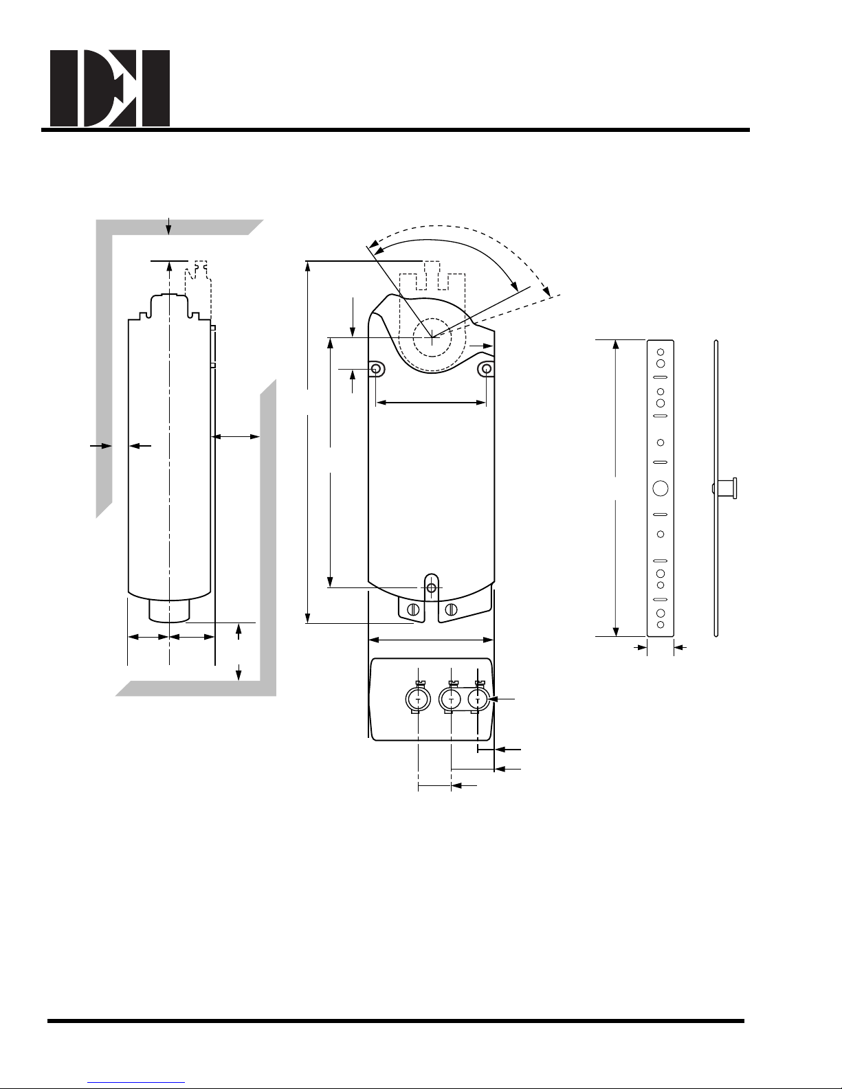
Figure 22. Dimensions of the ES142 Actuator and Mounting Bracket.
230 mm
EA0249R2
25/32 in
9 in
20 mm
129-270 EAI/ES-16 DEI, Inc.
Page 17

Dodge Engineering & Controls, Inc.
Toll Free (877) 334-2875 Fax: (978) 244-1422
ES142 Spring Return Electronic Actuators
Sizing Actuators for Damper Applications
The number of actuators required depends on several factors. To determine the
the installation:
1. Obtain damper torque ratings (ft-lb/ft
2. Determine the area of the damper.
3. Calculate the total torque required to move the damper:
Total Torque = Torque Rating x Damper Area
4. Select the total quantity of actuators, required:
Number of Actuators =
Total Damper Torque required
SF
(see note
below)
2
or Nm/m2) from the damper manufacturer.
x
Actuator T orque
(refer to
specifications)
Installation
quantity of actuators required for
NOTE: Whe
culating the number of actuators required, a safety factor (SF) should be included for
n cal
unaccountable variables such as slight misalignments, aging of the damper, etc. A suggested
safety factor is 0.80 (or 80% of the rated torque).
Mechanical coupling of the actuator is allowed if:
• The same type of actuator is used.
• The operating voltage is within the tolerance.
129-270 EAI/ES-17 DEI, Inc.
Page 18
Dodge Engineering & Controls, Inc.
Toll Free (877) 334-2875 Fax: (978) 244-1422
Installation
ES142 Spring Return Electronic Actuators
ACCESSORIES
NOTE: The auxiliary switches and/or the control signal adjustment cannot be added in the field. Order the
product number that includes the option(s), if required.
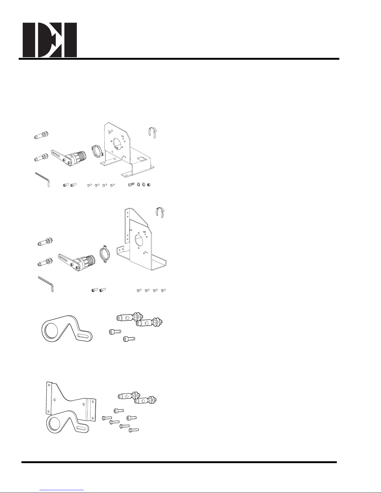
ASK71.1U This kit allows foot mounting of the ES142
actuator. This kit should be used for
in-the-airstream applications, and generally, anywhere
a foot-mounted actuator can be mounted.
This kit contains a crank arm that changes the angular
EA0477R2
Figure 1. Floor Mount Kit.
(4 each)
rotation into a
linear st
minimize side loading on the actuator’s output bearing,
a mounting bracket, and required mounting fasteners.
roke, a support bearing ring to
EA0476R2
Figure 2. Frame Mount Kit.
EA0495R1
Figure 3. Crank Arm Kit.
EA0494R1
Figure 4. Crank Arm Kit with Mounting Bracket.
ASK71.2U This kit allows mounting of the ES142
actuator directly to a damper frame. This kit should be
used with louvers and vents, and in applications where
use of the floor mount kit is not possible.
This kit contains a crank arm that changes the angular
rotation into a linear st
roke, a support bearing ring to
minimize side loading on the actuator’s output bearing,
a mounting bracket, and required mounting fasteners.
ASK71.3 This kit allows a direct coupled actuator to
provide an auxiliary linear drive. This crank arm kit can
be used to simultaneously drive a set of opposing or
adjacent dampers with a single actuator.
This kit includes a crank arm that attaches to the
splined hub
of the shaft adapter, and other required
mounting fasteners.
ASK71.4 This kit allows economical mounting of an
actuator to a variety of surfaces. This kit should be
used in applications where the actuator can be rigidly
surface mounted and a linear stroke output is required.
This kit includes a crank arm that attaches to the
splined hub
of the shaft adapter, a mounting bracket,
and other required mounting fasteners.
129-270 EAI/ES-18 DEI, Inc.
Page 19
Dodge Engineering & Controls, Inc.
Toll Free (877) 334-2875 Fax: (978) 244-1422
Installation
ES142 Spring Return Electronic Actuators
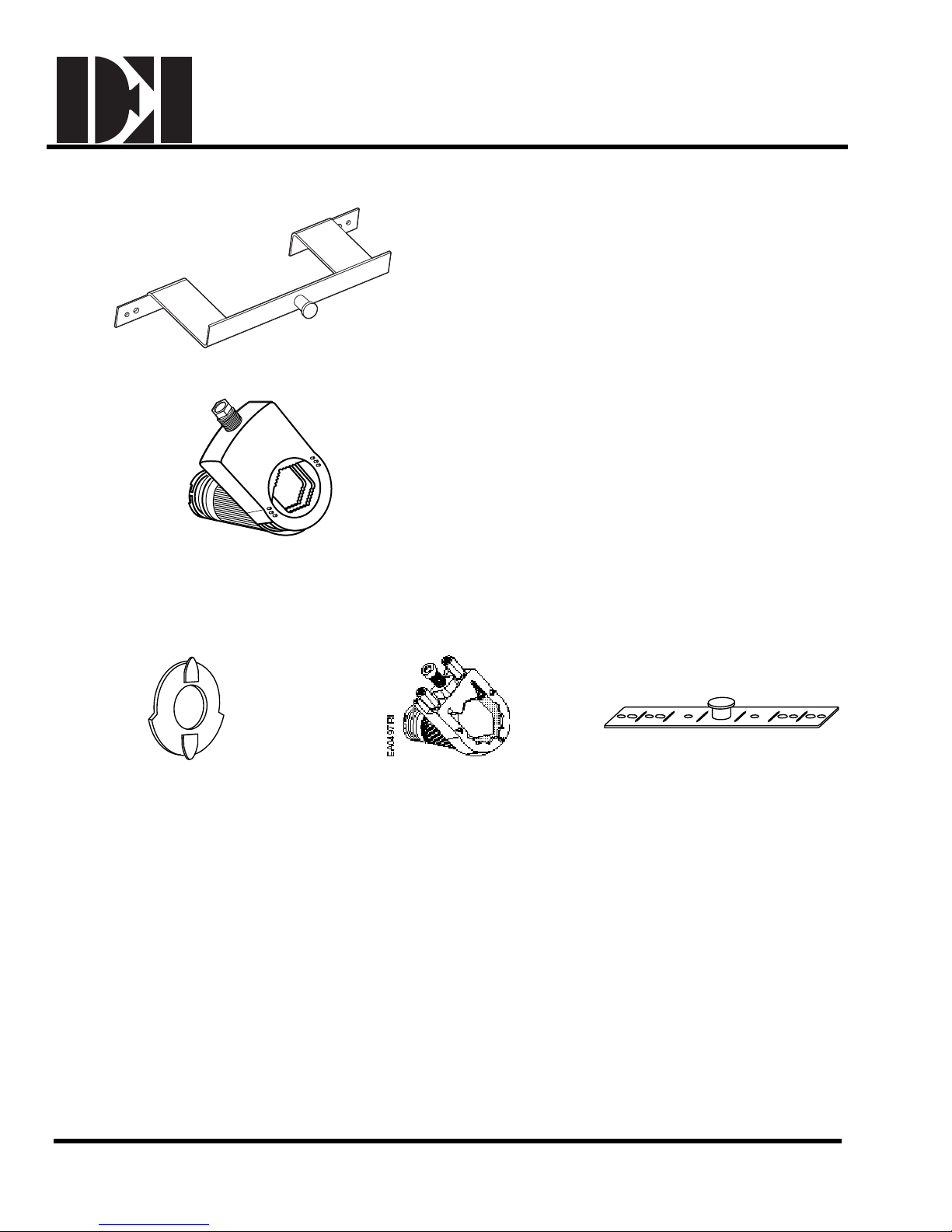
ASK73.1 This bracket provides an extended anti-
rotation pin that allows two ES142 actuators to directly
drive a single damper shaft. For use with two and
three–position actuators.
EA0496R1
Figure 5. Tandem Mount Bracket.
985-004 The self-centering shaft adapter will attach to
a shaft up to 1.00 inch (25.4 mm) in diameter. (The
special shaft adapter will attach to a 1.05-inch
(26.6-mm) diameter shaft.) This shaft adapter is
13/16-inches (20 mm) taller than the height of the
special shaft adapter.
EA0498R1
Figure 7. Self-centering Shaft Adapter.
Service Parts
EA0499R1
985-003
Position indicators (package of 10).
ASK74.1U
Special shaft adapter.
Figure 8. Orderable Parts.
EA0500R1
985-006
Anti-rotation (mounting) bracket.
129-270 EAI/ES-19 DEI, Inc
Page 20

Dodge Engineering & Controls, Inc.
Toll Free (877) 334-2875
ES142 Spring Return Electronic Actuator
Installation Guide
General Installation ..................................................................................................EAI/ES
Mounting...................................................................................................................EAI/ES – 1-4
– 1
Manual Override.......................................................................................................
Mechanical Range Adjustment
Mounting for NEMA 2...............................................................................................
DIP Switch Features.................................................................................................EAI/ES – 6
Dual Auxiliary Switch (-S option)
Zero Span Control Signal Adjust
Wiring........................................................................................................................EAI/ES – 8
General ..............................................................................................................EAI/ES – 8
Transformer........................................................................................................EAI/ES
Three-Position Control (24 VAC/DC).................................................................
Two-Position Control (24 VAC/DC)....................................................................EAI/ES
Two-Position Control (120 VAC)........................................................................EAI/ES
Three-Position (Floating) Control (24 VAC/DC).................................................
Modulating Control (24 VAC/DC).......................................................................EAI/ES – 10
Start-up/
Commissioning...........................................................................................
Two-Position Control (24 VAC/DC)....................................................................EAI/ES
Two-Position Control (120 VAC)........................................................................EAI/ES
Three-Position (Floating) Control (24 VAC/DC).................................................
Modulating Control (24 VAC/DC).......................................................................EAI/ES – 14
.................................................................................EAI/ES – 5
..............................................................................EAI/ES
ment (-ZS option)..................................................EAI/ES – 7
EAI/ES – 4
EAI/ES – 5
– 6
– 8
EAI/ES – 8
– 9
– 9
EAI/ES – 10
EAI/ES – 11
– 11
– 12
EAI/ES – 13
Ac
tuator Dimensions ................................................................................................
Actuator Sizing for Dampers.....................................................................................
Accessories ..............................................................................................................EAI/ES – 17-18
Item Number 129-270-08, Rev. BA
196 Riverneck Road, Chelmsford, MA 01824 Tel: (978)-244-1200 Fax: (978) 244-1422
EAI/ES – 15
EAI/ES – 16
 Loading...