

DEI DTS-1600A Datasheet
DTS-1600A
Dielectric Test
System
The use of Pulse Width Modulated
(PWM) types of adjustable speed
drives (ASD) in the electric motor industry has caused an increased incidence of premature wire insulation failure. The DTS-1600A is an integrated
test system designed to test the failure
behavior of insulation by simulating,
under controlled and accelerated conditions, the electrical and ther mal
stresses that characterize PWM
(inverter) motor controllers.
The DTS-1600A test system is designed to vary and monitor the electrical and thermal test parameters for up
to five samples simultaneously, including voltage, current, pulse width, frequency, voltage rate-of-rise time, duty
cycle and temperature. The control
and monitoring of these parameters
allows the user to study the insulation
failure mechanisms common to PWM
applications. This data can then be
used in the development of new motor
designs and insulation that will overcome these failure modes.
Compared to testing with an inverter,
the DTS-1600A can reduce the test
time from days per sample to minutes
per sample (time-to-failure with the
DTS-1600A is typically 1,000 times
faster than with an inverter), dramatically reducing research and development time for new insulating materials.
Equally important, full control over the
electrical and thermal test parameters
provides a reproducible test environ-
The Pulse Of The Future
Directed Energy, Inc.
• 2401 Research Blvd., Suite 108 • Fort Collins, CO 80526
TEL: 970-493-1901 • FAX: 970-493-1903 • EMAIL: deiinfo@directedenergy.com • Internet: http://www.directedenergy.com
• 5-Channel 3,200V Pulsed Test
System for Accelerated Breakdown
Testing of Motorettes, Twisted-Pair
and Dielectric Materials
• Variable Output Voltage, Pulse Rate-
of-Rise Time, Frequency, Duty Cycle
and Temperature
• Graphical User Interface and
Computer Control and Logging Of
Test and Oven Parameters
DTS-1600A Dielectric Test System
OPERATIONAL OVERVIEW
The DTS-1600A is designed to meet the testing
requirements of magnet wire manufacturers, motor designers and manufacturers, and manufacturers of varnish and insulating materials.
The DTS-1600A will test up to five samples
(twisted pairs, motorettes or dielectric material)
simultaneously. The samples are installed in the
oven to facilitate testing at controlled and elevated temperatures. The test parameters are controlled and monitored through the control computer. Each channel can be individually enabled
or disabled, and programmed for current trip
threshold and voltage rise and fall time. The pulse
frequency, pulse width, amplitude (voltage) and
oven temperature are shared by all five channels.
The system can simultaneously pulse five capacitive samples of 50pF (a typical twisted pair) per
sample or three samples of 350pF each (a typical
motorette) at 20KHz frequency at ±1600V (3200V
peak-to-peak) in bipolar mode. (Higher capacitance loads can be driven at derated voltage and/
or frequency.) It can also drive an inductive load,
such as a motor stator, of 3mH at up to 3.5µs
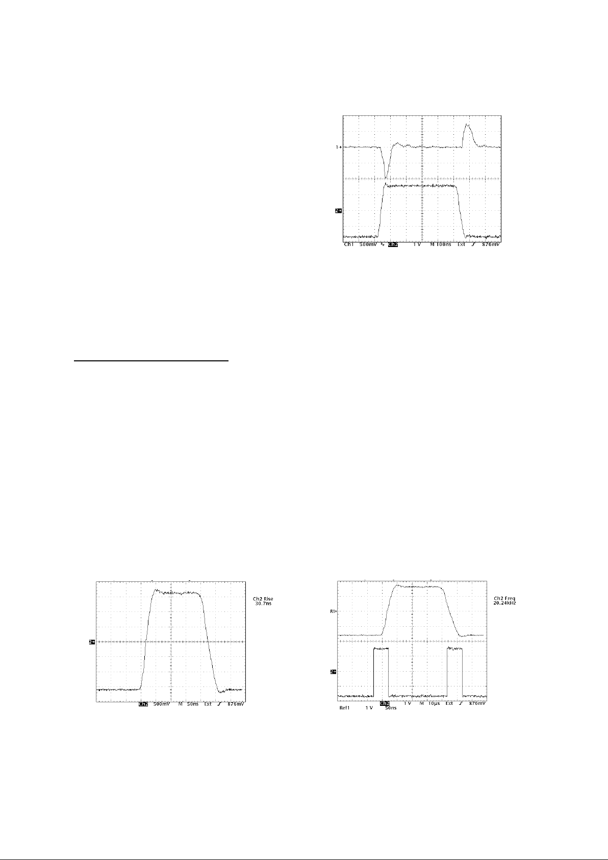
pulse width and 1600V (typical oper a tin g par ameters) in unipolar mode. Typical output wave forms
are shown in Figures 1, 2 and 3.
When a sample under test fails (the charging current exceeds the current threshold, indicating the
sample has shorted or arced), the channel is disabled, and the failure information is logged to a
text file and displayed on the Graphical User Interface (GUI) monitor. In addition to the parameters displayed and controlled through the GUI display, each channel has current and voltage monitor outputs that can be monitored using an oscilloscope or digitizer for real-time data acquisition
of the voltage and current profiles for each sample during operation.
The DTS-1600A is controlled by its control computer and GUI, which provides the interface be-
ment in which time-to-failure is repeatable within
statistically allowable differences. For all practical
purposes, inverters do not offer this capability.
In addition, the DTS-1600A offers other advantages over testing using an inverter. These advantages include:
• Capable of testing up to 5 samples simultaneously.
• User-controlled, variab le vo ltag e, curr ent trippoint, pulse width, frequency, duty cycle, voltage rise and fall time and sample temperature.
• Computer control and logging of the test parameters and failure data.
The DTS-1600A was developed in collaboration
with the U.S. Electrical Motors Division of Emerson Electric, utilizing a patented test technique
developed by USEM
(1)
.
(1) Licensed under US Patent
#5,648,725 and Copyright of the Emerson Electric Company, 1996
Figure 1
Typical rise time (~31ns) on fastest rise time setting, driving
a twisted pair (~50pF), ±1600V
Figure 2
Typical current (top trace) and voltage (bottom trace) wave-
forms, driving a twisted pair (~50pF), ±1600V
Figure 3
Typical voltage waveform (top trace) at 20KHz repetition
rate (bottom trace), driving a twisted pair (~50pF), ±1600V
 Loading...