

DEI DLD-127A Datasheet
THE PULSE OF THE FUTURE
DIRECTED
ENERGY
INCORPORATED
DLD-127A
• Output Current 4A To 40A
• Output Voltage Up To 10V
• Pulse Width < 50µ
µµ
µstoDC
• Rise Time ≤
≤≤
≤ 25µµµµs
• Analog Modulation to 10KHz
• Constant Current Or
Constant Power Control
• High Efficiency
• OEM Module
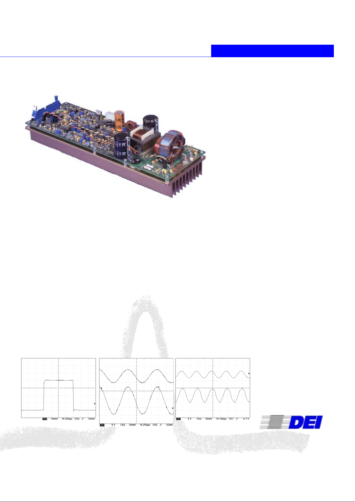
The DLD-127A is a 400 watt laser diode driver/current
source designed to drive laser diodes and other lowimpedance loads at up to 10 volts and 40 amps. It is
optimized for diode pumping of solid state lasers,
illumination, and other high power applications.
The DLD-127A can be operated continuously (CW),
pulsed (Quasi-CW) or can be analog modulated by an
external analog modulation input. It can generate output
pulse widths of ≤50µstoDCatupto10KHz,withan
analog modulation bandwidth of 10KHz.
The DLD-127A can be operated in either laser current
(constant current) or optical power (constant power)
control modes. The control mode is user-selectable, and
signals to monitor the output current are available through
the user interface connector. In constant power control
mode, a user-supplied photodiode may be connected to
the DLD-127A to provide optical feedback to control the
current source through the on-board photodiode amplifier.
In constant current control mode, the laser current is
monitored, and controls the driver output. The output
current and voltage are also compared to the internal and
external over-current setpoints, and to the internal overvoltage setpoint, to determine an over-current or overvoltage fault.
Designed for OEM applications, the DLD-127A derives its
high current output from a 24VDC to 48VDC input DC
power supply, and +5VDC and ±15VDC support power.
The analog modulation and output current setpoints are
controlled by 0-10V analog inputs.
The driver is a high efficiency switch-mode current source.
This architecture provides an efficiency greater than 75%,
minimizing power dissipation and cooling requirements.
Safety features include a power up reset hardware delay,
driver power-on indicator, laser over-voltage and overcurrent faults, and a driver over-temperature fault.
The DLD-127A is provided on an air-cooled heatsink,
ready for installation and assembly in OEM applications.
40A CW & QUASI-CW LASER
DIODE DRIVER/CURRENT SOURCE
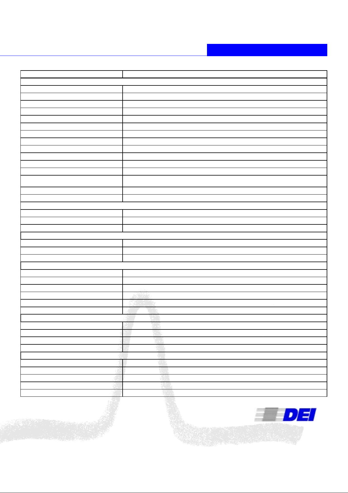
40A Output Waveform
250µs/Div Horizontal Scale, 10A/Div
Vertical Scale
34A Analog Modulation @ 1KHz
(18A Bias, ±17A Modulation)
Top Trace = InputSignal
Bottom Trace = Output Current
250µs/Div Horizontal Scale, 10A/Div
Vertical Scale(Bottom Trace)
20A Analog Modulation @ 5KHz
(20A Bias, ±10A Modulation)
Top Trace = InputSignal
Bottom Trace = Output Current
100µs/Div Horizontal Scale, 10A/Div
Vertical Scale(Bottom Trace)
THE PULSE OF THE FUTURE
Directed Energy, Inc.
2401 Research Blvd., Suite 108
Fort Collins, CO USA 80526
970-493-1901 Fax: 970-493-1903
Email: deiinfo@directedenergy.com
Web: http://www.directedenergy.com
9200-0206 REV1
SPECIFICATIONS SUBJECT TO CHANGE WITHOUT NOTICE
(1) The DLD-127A will operateon any voltage from 24VDC to 48VDC, however
the maximum output voltage with 24VDC input is 5V. To obtain the full 10V
output, 48V input is required.
PARAMETER VALUE
Laser Diode Controller
Voltage Polarity Positive with respect to ground
Maximum Output Voltage 10V @ 40A
Current Range 0A to 40A
Maximum Duty Cycle 100%
Pulse Width
50µs to DC, controlled by modulation input
Pulse Rise Time/Fall Time
Controlled by modulation input, minimum rise and fall time is 25µs, maximum bandwidth is≥10KHz
Droop <1%
Overshoot <5% maximum, typically <2%
Undershoot <2%
Ringing (Pulse Mode) <5%
Noise and Ripple (After initial edge, steady state)
≤
1%
Output Power Stability
≤
0.5% over 24 hours at full power, measured at 25°C with temperature variation <±0.5°C into a re-
sistive load
Temperature Coefficient
≤
250ppm/°Cfrom0°Cto40°C
Efficiency >75%
External Modulation Input
Input Signal 0 to +10V
Bandwidth DC to 10KHz
Transfer Function 4000mA/V
Control And Monitor Inputs
Reset
TTL into 50Ω
to reset driver faults
Current Limit 0-10V Analog Voltage Setting, range of 4A to 40A
Laser Diode Enable TTL into 1k Ohm, High=Enabled
Control And Monitor Outputs
Output Current Monitor
4A/V into 1M
Ω
Laser Over Current Fault Open collector output, 50mA max current sink, Low=Fault, Imax + 10% latches off driver
Laser Over Voltage Fault Opencollector output, 50mA max current sink, Low=Fault, Vmax + 10% latches off driver
Over Temperature Fault Open collector output, 50mA max current sink, latches off driver
Driver Power On Driver Power Indicator, Open collector output, 50mA max current sink, Low=Fault
Driver Fault Open collector output, 50mA max current sink, Low=Fault, latches off driver
Photodiode Amplifier
Photodiode Amplifier Output 0 to 10V output
Photodiode amplifier gain Adjustable
Photodiode bias voltage 10V
Bandwidth Limit 100KHz
General
Operating Temperature Range
0°Cto+40°C
Power Requirements
48VDC @ 12A
(1)
;±15VDC @ 0.25A; +5VDC @ 0.5A
Cooling Requirements
Forced Air, 100 CFM, max air temperature 40°C
Dimensions (W x L x H, including heatsink) 4” x 12” x 3” (102mm x 305mm x 76mm)
Depth Of Modulation 90% @ 1KHz, 50% @ 5KHz, 20% @ 10KHz
Weight (Including Heatsink) 51 Ounces (1.45 Kilograms)
SPECIFICATIONS
(Measured at 40A, 10V output)
 Loading...